Abstract
Insufficient daylighting can negatively affect working quality and productivity and increase lighting energy consumption in buildings. Particularly, the western orientation has a non-uniform daylighting distribution, especially at the zone next to the window resulting from the unequal radiation distribution of sunlight. Therefore, this study presents an innovative system known as Integrated Kinetic Fins (IKF), which can respond parametrically to the sun’s movement; to enhance the daylighting distribution during the late working hours for the western façades and decrease the high illuminance daylighting spots near the windows. The study optimizes the fin parameters based on a selected territory; then, the fi angles are automatically controlled. The IKF is applicable in regions with clear skies and low solar altitudes. Finally, a comparison between a traditional kinetic system and the IKF is made, and the results are reported. The system shows an enhancement of daylight distribution during these late hours, where the contrast has been improved by 22% and uniformity has been enhanced by 10%, which consequently contributes to reducing potential glare.
1. Introduction
In hot climate zones, solar radiation is quite high, which usually produces undesired solar heat gain in addition to excessive indoor daylighting. On the other hand, having sufficient natural lighting in office spaces influence occupants’ productivity [1,2,3]. Additionally, the more uniform distribution of daylight, the better the visual comfort and the less energy consumed for lighting [1,4,5]. Therefore, daylighting should be efficiently exploited [6].
Several studies focused on southern façades as they have the most intensive radiation; they investigated the design of fixed and kinetic louvres [6,7,8,9]. Other studies improved the blinds’ design and materials [8,10], including complex fenestration systems [11,12]. However, there was a lack of focus on the western façades, although they are considered the most challenging facades due to the extreme steepness of solar altitude at such orientation, which can potentially result in high temperatures [13]. Alternatively, previous studies have recommended either avoiding west-east orientation by using solely the north–south orientation [13], or at least minimizing the glazing area on the western facades as much as possible. Others used fixed vertical solutions; however, they are not always optimum. They need to be tilted to provide efficient protection, which likely prevents the exterior view and potentially blocks daylight penetration in winter [14].
Since western openings are exposed to the low solar altitudes in summer, they require extra-deep light fins, ribbon windows, shelves, and a special view window that can decrease the penetration of excessive daylighting [13,15]. However, far too little attention has been paid to the western façade. The only suggested recommendations are to provide west façades with less glazing, as low angle altitudes in late afternoon transmit significant heat gain into interior spaces [16] or to avoid west glazing as much as possible. Some studies recommended using a dynamic system (e.g., an outdoor automated louvre). Others used dynamic translucent solar screens to avoid exceeded glare [17] or used machine learning to control the façade and remove the probable glare [18].
Attempts have been made to design an adaptive façade that considers both minimizing glare and thermal discomfort [19] via using parametric design while taking into consideration visual comfort [14,20]. Considerable research has used the optimization method by presenting multiple scenarios to design internal shading devices in Indonesia [21]. Some researchers have studied the impact of different control strategies of perforated curved louvres on visual comfort and energy consumption [22]. Further study investigated glare protaction by using “split louvre system” that based on two horizontal louver system controlled parametrically [23], or by using a horizontal fixed shading as an element of the building’s façade to reduce glare and decrease energy consumption [24].
Currently, conventional kinetic fins (CKF) are used as a solution to provide daylight at the western façade; however, due to the identical angle for all fins, they do not deliver uniform light inside the space because of the unequal amount of solar radiation on the western façade compared to southern façade, as seen in Figure 1a. It can be seen in Figure 1b that most of the daylight concentrates in the back area of the room, which results in a high illuminance spot.
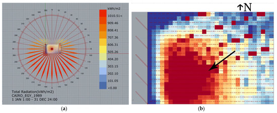
Figure 1.
The unequal radiation on the western façade compared to the southern façade (a), the spot of the high illuminance values on the southwest location, (b).
Considering this issue, this study presents integrated kinetic fins (IKF) for office buildings oriented towards the west, which can reduce potential glare and provide uniform daylight. The system uses parametric optimization techniques to improve the indoor daylighting distribution during late working hours by responding to the sun’s movement. Parametric design enables designers to create, manage, and organize complex and dynamic models by integrating different parameters. It opens up a variety of choices and opportunities for potential development and gives the models the ability of responsiveness [25]. IKF can adapt to the solar azimuth and respond to the solar altitude by horizontal blinds. The system can potentially handle the non-uniform daylighting next to the window. For daylighting calculation, various simulation software programs have been used. This study aims to improve the daylighting distribution inside the room for the western façade up to 85% via using IKF within an illuminance level of 200–1000 lux [26].
2. Methodology
The system works efficiently for climates with clear sky conditions. The study compares the outcome of using CKF with IKF for a case study in Cairo, Egypt. A simulation process is performed by linking Honeybee and Grasshopper as an open-source parametric plugin that is equipped with Radiance and DAYSIM simulation engines. Grasshopper is used to generate 3D parametric models to be connected to Honeybee and Ladybug for daylight assessment and environmental analysis (Honeybee and Ladybug) plugins, which are used as an engine for Radiance and EnergyPlus software. Figure 2 illustrates the relationship between these software [27].
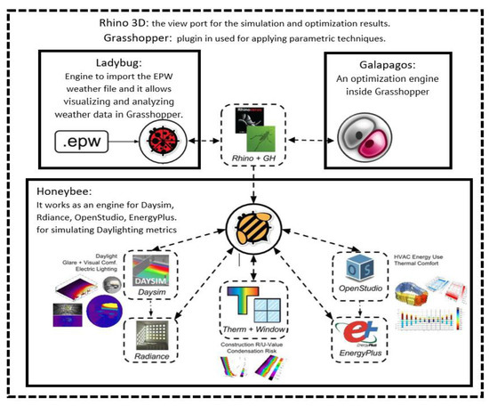
Figure 2.
The links between Rhinoceros, Grasshopper, Galapagos, Honeybee, and Ladybug to generate an environmentally conscious model and simulation.
2.1. Description of the System
The Integrated Kinetic Fins contain between (3–8) vertical fins and two horizontal blinds, which can respond automatically to sunlight angles; see Figure 3. The fins and blinds are made of aluminum slats with 80% reflectivity. The method compares the performance of three different shading systems (fixed fins, CKF, and IKF). Fins angles are calculated from the perpendicular of the façade. The model is a typical office room in new Cairo in an office building. It is oriented toward the west. Its dimensions are 4.00 m width, 8.00 m depth, and 4.20 m height finish to finish. The west facade has 70% opening. The target illuminance is between 200–1000 lux for at least 70% of the space, with better distribution for daylighting, as shown in Figure 3. The office is usually occupied from 8:00 a.m. to 5:00 p.m. The study was applied at late working hours, between 3:00–5:00 p.m., for the 21st of each year month. Ladybug uses (EPW) weather file to provide full sun path parameters for the studied location.
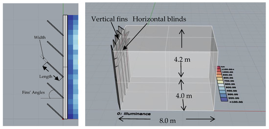
Figure 3.
The test cell, the multi-angular vertical fins, and the horizontal responsive blinds (IKF).
2.1.1. Conventional Kinetic Fins (CKF)
The fin’s geometries are built with predetermined parameters and are connected to the genome of Galapagos (Grasshopper component for optimization). The simulation was run on three different dates for each optimization process: 21st of June, 23rd of September, and 20th of March.
The parameters have two categories; some parameters are fixed. The room height is 4.2 m, and the fins’ height is 4.2 m. The fins’ angles are 55° in March, 60° in June, and 45° in September; the angles were optimized using Galapagos component in Grasshopper before the simulation, see Table 1. The fins in this system move automatically together with the same angle for each fin.

Table 1.
Optimization process of the kinetic fins.
2.1.2. Parametric Kinetic Fins (PKF)
Instead of having the same rotation angle for all the fins at a specific time, each fin has its rotation angle for each hour, similar to the parametric louvre system [10,28]. Data are recorded after optimization and added to a python switcher to switch automatically between the results. Each time has starting angle and stepping angle for fins. These angles are optimized using Galapagos and given to the switcher.
2.1.3. Integrated Kinetic Fins (IKF)
Finally, two extra horizontal blinds are added to generate the integrated system that can handle the altitude angle of the sunlight, using the same methodology as the advanced parametric louvre system used by [29], see Figure 4.
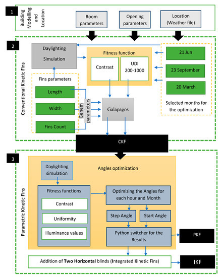
Figure 4.
The framework for the proposed system.
2.2. Performance Metrics
Daylighting performance is generally monitored by calculating its illuminance level according to specific standards [30,31], in addition to providing sufficient amount of light to achieve human visual comfort, i.e., with no glare or excessive light [31,32]. For the optimization processes in our case, three daylight metrics were used: contrast, uniformity, and illuminance values. This system aims to minimize “contrast”, maximize “uniformity”, and increase “the desirable illuminance values between 200–1000”, and these metrics are categorized as follows:
2.2.1. Contrast and Uniformity
Contrast can be defined as the ratio between the light falling on a task and the general lighting in the surrounding area, and this contrast can produce a patch of caustics in this area, which accordingly cause glare that potentially influence human visual comfort. Illuminance values can be simulated/measured, and contrast ratios can be computed to determine the amount of glare [27,33]. The smaller the value, the better the indoor light quality. In this study, Contrast can be calculated by finding the difference between the illuminance values average for both areas, next to the window and in the deep-plan room, as shown in Figure 5.
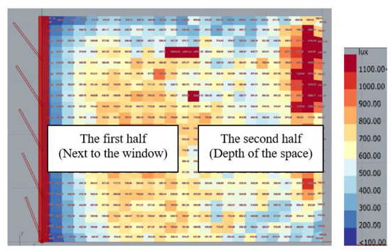
Figure 5.
Illuminance value at the deep-plan area is higher than the area near the window, which can potentially cause glare.
The Chartered Institution of Building Services Engineers (CIBSE) has identified two varieties of studying lighting: uniformity and contrast [34]. Uniformity explains how evenly the light is spread on a surface in a space. It is calculated as the proportion of the minimum/maximum illuminance to the average illuminance across the task area, while contrast is the proportion of the minimum to the maximum illuminance [33,35]. Indeed, there is a clear relation between contrast and uniformity, i.e., the lower the contrast, the better the uniformity.
2.2.2. Illuminance Values
In each individual simulation, a percentage value of illuminance between 200 and 1000 lux [28] is calculated. For any static case, useful daylight illuminance (UDI) can be used as an annual metric calculation; however, it cannot be used for kinetic solutions; therefore, this study uses a case-by-case calculation method because the fins are changing at every single step. It should bear in mind that case-by-case here means that simulation should run every single time for each movement, i.e., we cannot do one annual simulation for the system at once because the system is movable and responds to the sun’s movement every 10 min. Accordingly, each movement has its special case.
3. Modelling and Optimization Process
3.1. Dimensions Adjustment for the Fins
The optimization solver runs while fixing the angles of the fins at 45°. The processes produce many values for each month. The study selects 10 values for each case and writes them up. Table 2 shows the optimization results of the fixed parameters in three different months, March, June, and September. On 21 March, the optimum parameters are 0.04 m width and 0.8 m length, and five fins, while on 21 June, the optimum parameters are: 0.037 m width, 0.75 m length, and five fins. On 21 September, the optimum parameters were 0.03 m width, 0.83 m length, and five fins. The average parameters of the three months are 0.035 m width, 0.80 m length, and five fins. These parameters are used as constant parameters in optimizing the angles. The optimization process was performed in Grasshopper using Galapagos. Based on the optimization process, the fins’ count is assigned based on this simple equation: N = W/0.8, where (N) is the fins’ count and (W) is the width of the façade. As in our case, room width equals (4.2 m) divided by the optimized fins’ count (5), resulting in (0.8).
Table 2.
Optimization process of the fin’s parameters in March, June, and September.
3.2. Daylighting Distribution Using IKF
The optimization was made on the 21st of each month. Figure 6 shows the daylighting simulation in August at late working hours, 3:00–5:00 p.m. It shows the improvement of the daylighting distribution by using the proposed system IKF compared to the other systems [32,36].
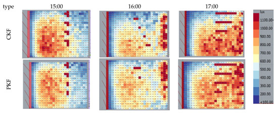
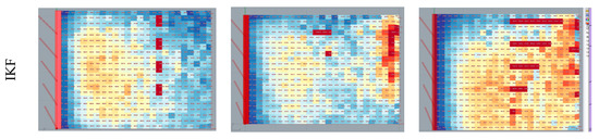
Figure 6.
Improvement of the daylighting distribution by using IKF compared to the other systems.
4. Results and Discussion
When using CKF, solar radiation is dramatically concentrated at the lower part of the southwestern area of the space, see Figure 6, which is considered a typical orientation for fins. This study proposes an advanced kinetic shading system (IKF) that can improve daylighting distribution during late working hours between 15:00–17:00, where sun rays can reach the deepest area of the spaces. The process of generating IKF includes four stages: firstly, optimizing the fixed parameters for the fins; these optimum parameters are 0.3 m width, 0.81 m length, and a total of five fins. Then, these parameters are fixed for use in optimizing PKF. In this stage, fins angles are optimized at each hour. Fins’ angles and times are collected and added to a python switcher to ease the application process for any different cases, see Table 3. Finally, two horizontal blinds are added to the system with the ability to respond to the altitude angle of the sun that produces the IKF.
Table 3.
Optimized values for the IKS Source: The Author.
The research compares using PKF and IKF with the CKF. The assessment depends on three metrics: contrast, uniformity, and illuminance values between 200–1000 in percentage.
It is apparent from Figure 6 that using CKF produces a patch of concentrated illuminance at the deep area of the space as it provides the same angle for all fins. The PKF slightly enhances the daylight distribution while it includes different angles for each fin, while these angles have specific sequences in order to deal with the patchy solar distribution at the western façade. The greater the angle values, the more light the fins can allow to enter the space, and vice versa. The IKF is observed to improve the daylighting distribution and increase the desired illuminance percentage values due to its integrated characteristics by dealing with solar altitude through the horizontal louvres that control the contrast. The contrast is noticeably decreased by using PKF and IKF at 10% and 22%, respectively, compared to CKF. That means the difference between the illuminance values in a deep location of the room and the values next to the window became lower by 22%. For instance, if the difference between the highest and lowest illuminance values is 1000 lux, IKF can potentially enhance the results to 780 lux, see Figure 7.
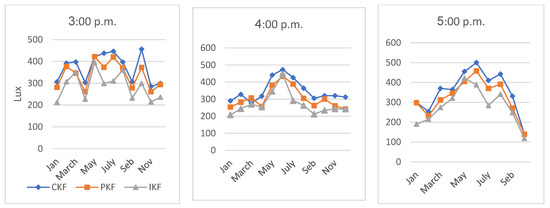
Figure 7.
The contrasts (difference between maximum and minimum illuminance) for the three proposed systems.
The uniformity in Figure 8 is improved by 9% by using the PKF and 10% by using IKF, as the former can only deal with the deep plan areas, but both systems can enhance uniformity. Enhancement is also notable in the summer months in June and July, while October enhancement exceeds 31%. In the winter months, there is no significant difference in contrast, as well the uniformity, due to the very low altitude of solar radiation. It should bear in mind that the high illuminance daylighting points near the windows can be reduced by even using our proposed method (IKF) or by using translucent windows or electrochromic glazing, which can respond automatically to the intensity of solar radiation [28,37]. However, the proposed system (IKF) is mainly focused on improving daylight distribution in the western facades with deep plan areas.
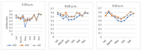
Figure 8.
The uniformities and illuminance ratios (minimum illuminance value divided by maximum illuminance value) for the three proposed systems.
Figure 9 shows an increase in the percentage by 3% and 5% via using PKF and IKF, respectively. The values did not highly improve by using the proposed system as it focused on the distribution of daylighting regardless of the values. In this sense, the values can be between the accepted limits, but the difference between them is still high. Thus, enhancing the illuminance values does not mean having good uniformity and contrast, which refers to a good daylight distribution. That clarifies why IKF and PKF have better improvement for contrast and uniformity than illuminance value. Generally, when the sun’s rays reach the deepest area in space, IKF and PKF can provide better results than CKF since both systems can respond to the azimuthal angle of the sun’s rays.
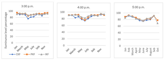
Figure 9.
Illuminance level percentage between 200–1000 lux, as a result of three proposed systems.
The study investigated the performance of IKF in Cairo, Egypt, and it can be applied to western façades in all hot arid zone. The can system deals successfully with low solar altitudes; however, it has not been examined for different sky types.
5. Conclusions and Future Studies
The study proposed an Integrated Kinetic Fins system that can enhance the daylighting for west-oriented office buildings (at late working hours, 3:00 p.m. to 5:00 p.m.) using a parametric design and optimization method. The study used the contrast and uniformity function indices and illuminance values to analyze the daylight performance of the space.
The IKF was composed of vertical and horizontal slats to control the sun’s rays. The responsive horizontal elements were added to mitigate high illuminance in the area next to the windows during late working hours. IKF provided apportionments to respond to the sun rays by the kinetic system with specified alignment and movements for each fin. The sequence of the angular system enhanced the distribution of daylighting in the space. The use of the parametric technique gave the fixability to optimize and control the fin parameters and the angles.
The contrast was decreased by 22% using Integrated Kinetic Fins (at least 9%) compared to the conventional ones. Moreover, the uniformity and percentage of desirable illuminance values were improved by 10% and 5%, respectively, by using IKF.
In the future, the system will be validated by applying it in different case studies located in some hot climate zones. Moreover, the framework can be applied in different locations with different climate conditions. These data will then be used as a dataset for machine learning algorithms. The algorithm will determine the fin’s angles for all the zones in order to generalize the solution to fit locations all over the world.
Author Contributions
M.K.F.: writing up the original work, methodology, data collection, and simulation. A.E.: revising and editing, research structure, methodology, and data collection. R.A.R.: revising and editing and data analysis. N.I.: critical revisions. All authors have read and agreed to the published version of the manuscript.
Funding
This research received no external funding.
Data Availability Statement
The data of this research was based on Software simulation and parametrical analysis.
Conflicts of Interest
The authors declare that they have no known competing financial interests or personal relationships that could have appeared to influence the work reported in this paper.
References
- Bugeat, A.; Beckers, B.; Fernández, E. Improving the daylighting performance of residential light wells by reflecting and redirecting approaches. Sol. Energy 2020, 207, 1434–1444. [Google Scholar] [CrossRef]
- Compagnon, R. Solar and daylight availability in the urban fabric. Energy Build. 2004, 36, 321–328. [Google Scholar] [CrossRef]
- Lim, Y.-W.; Kandar, M.Z.; Ahmad, M.H.; Ossen, D.R.; Abdullah, A.M. Building façade design for daylighting quality in typical government office building. Build. Environ. 2012, 57, 194–204. [Google Scholar] [CrossRef]
- Eltaweel, A.; Su, Y. Parametric design and daylighting: A literature review. Renew. Sustain. Energy Rev. 2017, 73, 1086–1103. [Google Scholar] [CrossRef]
- Hopkinson, R.G. Glare from daylighting in buildings. Appl. Ergon. 1972, 3, 206–215. [Google Scholar] [CrossRef]
- Urbano Gutiérrez, R.; Du, J.; Ferreira, N.; Ferrero, A.; Sharples, S. Daylight control and performance in office buildings using a novel ceramic louvre system. Build. Environ. 2019, 151, 54–74. [Google Scholar] [CrossRef]
- Konis, K.; Lee, E.S. Measured daylighting potential of a static optical louver system under real sun and sky conditions. Build. Environ. 2015, 92, 347–359. [Google Scholar] [CrossRef]
- Konstantoglou, M.; Tsangrassoulis, A. Dynamic operation of daylighting and shading systems: A literature review. Renew. Sustain. Energy Rev. 2016, 60, 268–283. [Google Scholar] [CrossRef]
- Meresi, A. Evaluating daylight performance of light shelves combined with external blinds in south-facing classrooms in Athens, Greece. Energy Build. 2016, 116, 190–205. [Google Scholar] [CrossRef]
- Eltaweel, A.; Su, Y. Controlling venetian blinds based on parametric design; via implementing Grasshopper’s plugins: A case study of an office building in Cairo. Energy Build. 2017, 139, 31–43. [Google Scholar] [CrossRef]
- Ullah, I.; Shin, S. Highly concentrated optical fiber-based daylighting systems for multi-floor office buildings. Energy Build. 2014, 72, 246–261. [Google Scholar] [CrossRef]
- Yu, X.; Su, Y.; Zheng, H.; Riffat, S. A study on use of miniature dielectric compound parabolic concentrator (dCPC) for daylighting control application. Build. Environ. 2014, 74, 75–85. [Google Scholar] [CrossRef]
- Aste, N.; Butera, F.M.; Adhikari, R.S.; Leonforte, F. Sustainable Building Design for Tropical Climates. In Innovative Models for Sustainable Development in Emerging African Countries; Aste, N., Della Torre, S., Talamo, C., Adhikari, R.S., Rossi, C., Eds.; Springer International Publishing: Cham, Switzerland, 2020; pp. 37–46. [Google Scholar]
- Kirimtat, A.; Koyunbaba, B.K.; Chatzikonstantinou, I.; Sariyildiz, S. Review of simulation modeling for shading devices in buildings. Renew. Sustain. Energy Rev. 2016, 53, 23–49. [Google Scholar] [CrossRef]
- Al-Tamimi, N.A.M.; Fadzil, S.F.S.; Harun, W.M.W. The effects of orientation, ventilation, and varied WWR on the thermal performance of residential rooms in the tropics. J. Sustain. Dev. 2011, 4, 142. [Google Scholar] [CrossRef]
- Napier, J. Climate Based Façade Design for Business Buildings with Examples from Central London. Buildings 2015, 5, 16–38. [Google Scholar] [CrossRef]
- Lu, Y.; Liu, S.W.; Hong, Y.D.; Xiao, Y.Q. Multivariable Optimization of Dynamic Translucent Solar Screen on West-Facing Offices. IOP Conf. Ser. Earth Environ. Sci. 2019, 238, 012042. [Google Scholar] [CrossRef]
- Wang, Y.; Han, Y.; Wu, Y.; Korkina, E.; Zhou, Z.; Gagarin, V. An occupant-centric adaptive façade based on real-time and contactless glare and thermal discomfort estimation using deep learning algorithm. Build. Environ. 2022, 214, 108907. [Google Scholar] [CrossRef]
- Wu, H.; Zhang, T. Optimal design of complex dynamic shadings: Towards sustainable built environment. Sustain. Cities Soc. 2022, 86, 104109. [Google Scholar] [CrossRef]
- Rizi, R.A.; Eltaweel, A. A user detective adaptive facade towards improving visual and thermal comfort. J. Build. Eng. 2021, 33, 101554. [Google Scholar] [CrossRef]
- Mangkuto, R.A.; Koerniawan, M.D.; Apriliyanthi, S.R.; Lubis, I.H.; Atthaillah; Hensen, J.L.M.; Paramita, B. Design Optimisation of Fixed and Adaptive Shading Devices on Four Façade Orientations of a High-Rise Office Building in the Tropics. Buildings 2021, 12, 25. [Google Scholar]
- Uribe, D.; Vera, S.; Bustamante, W.; McNeil, A.; Flamant, G. Impact of different control strategies of perforated curved louvers on the visual comfort and energy consumption of office buildings in different climates. Sol. Energy 2019, 190, 495–510. [Google Scholar] [CrossRef]
- Alsukkar, M.; Hu, M.; Eltaweel, A.; Su, Y. Daylighting performance improvements using of split louver with parametrically incremental slat angle control. Energy Build. 2022, 274, 112444. [Google Scholar] [CrossRef]
- Martokusumo, W.; Koerniawan, M.D.; Poerbo, H.W.; Ardiani, N.A.; Krisanti, S.H. Algae and building façade revisited. a study of façade system for infill design. J. Archit. Urban. 2017, 41, 296–304. [Google Scholar] [CrossRef]
- Boyer, M.C. On modelling complexity and urban form. Archit. Des. 2015, 85, 54–59. [Google Scholar] [CrossRef]
- Eltaweel, A.; Su, Y. Evaluation of Suitability of a Parametrically Controlled Louvers for Various Orientations throughout a Year Comparing to an Existing Case. Buildings 2017, 7, 109. [Google Scholar] [CrossRef]
- Eltaweel, A.; Su, Y.; Mandour, M.A.; Elrawy, O.O. A novel automated louver with parametrically-angled reflective slats; design evaluation for better practicality and daylighting uniformity. J. Build. Eng. 2021, 42, 102438. [Google Scholar] [CrossRef]
- Eltaweel, A.; Yuehong, S. Using integrated parametric control to achieve better daylighting uniformity in an office room: A multi-Step comparison study. Energy Build. 2017, 152, 137–148. [Google Scholar] [CrossRef]
- Eltaweel, A.; Su, Y.; Lv, Q.; Lv, H. Advanced parametric louver systems with bi-axis and two-layer designs for an extensive daylighting coverage in a deep-plan office room. Sol. Energy 2020, 206, 596–613. [Google Scholar] [CrossRef]
- Rea, M.S. The IESNA Lighting Handbook: Reference & Application; Illuminating Engineering Society of North America: New York, NY, USA, 2000. [Google Scholar]
- Baker, N.; Steemers, K. Daylight Design of Buildings: A Handbook for Architects and Engineers; Routledge: Oxford, UK, 2014. [Google Scholar]
- Kent, M.G.; Altomonte, S.; Tregenza, P.R.; Wilson, R. Discomfort glare and time of day. Light. Res. Technol. 2015, 47, 641–657. [Google Scholar] [CrossRef]
- Chraibi, S.; Crommentuijn, L.; Loenen, E.v.; Rosemann, A. Influence of wall luminance and uniformity on preferred task illuminance. Build. Environ. 2017, 117, 24–35. [Google Scholar] [CrossRef]
- Cibse. CIBSE guide C: Reference Data; Routledge: Oxford, UK, 2007. [Google Scholar]
- Kruisselbrink, T.; Dangol, R.; Rosemann, A. Photometric measurements of lighting quality: An overview. Build. Environ. 2018, 138, 42–52. [Google Scholar] [CrossRef]
- Kent, M.G.; Altomonte, S.; Wilson, R.; Tregenza, P.R. Temporal effects on glare response from daylight. Build. Environ. 2017, 113, 49–64. [Google Scholar] [CrossRef]
- Granqvist, C.G.; Arvizu, M.A.; Pehlivan, İ.B.; Qu, H.-Y.; Wen, R.-T.; Niklasson, G.A. Electrochromic materials and devices for energy efficiency and human comfort in buildings: A critical review. Electrochim. Acta 2018, 259, 1170–1182. [Google Scholar] [CrossRef]


Disclaimer/Publisher’s Note: The statements, opinions and data contained in all publications are solely those of the individual author(s) and contributor(s) and not of MDPI and/or the editor(s). MDPI and/or the editor(s) disclaim responsibility for any injury to people or property resulting from any ideas, methods, instructions or products referred to in the content. |
© 2023 by the authors. Licensee MDPI, Basel, Switzerland. This article is an open access article distributed under the terms and conditions of the Creative Commons Attribution (CC BY) license (https://creativecommons.org/licenses/by/4.0/).