Article

Characterization of Mechanical Behavior of Ultra-Small Clearance Tunnel Construction in Upper Soil and Lower Rock Composite Strata

1
College of Civil Engineering, Central South University, Changsha 410000, China
2
China Railway No.17 Bureau Group Fifth Engineering Co., Ltd., Taiyuan 030032, China
*
Author to whom correspondence should be addressed.
Buildings 2023, 13(2), 559; https://doi.org/10.3390/buildings13020559
Submission received: 8 January 2023 / Revised: 1 February 2023 / Accepted: 13 February 2023 / Published: 17 February 2023
(This article belongs to the Special Issue Tunnel Construction and Underground Space Technology)

Abstract

:
It is hard to grasp the deformation law of the surrounding rock and the force characteristics of the support structure during the construction of ultra-small clearance tunnels in upper soil and lower rock composite strata. Based on the ultra-small clearance tunnel in Li Shuping, Tongxin Expressway, Guizhou, this paper adopted a combination of numerical simulation and field monitoring to analyze the influence of different burial depths and soil-rock interface positions on the deformation of the surrounding rock and the internal forces of the support structure of the ultra-small clearance tunnel. The conclusions are: (1) the monitoring data show that the stress in the steel frame of the leading tunnel increases first by the influence of proximity construction, and then decreases and reaches a stable value after the secondary lining is applied, and the stress at the arch waist of the soft soil layer furtherest from the side of the middle rock column is greater than that in the rock layer on the side of the middle rock column; (2) the position of the soil-rock interface has a significant influence on the initial support force of the first tunnel, and the bending moment of the structure increases with the downward movement of the soil-rock interface and the increase in the burial depth; (3) the influence of the soil-rock interface position on the initial support moment of the first tunnel is greater than the influence of proximity construction, a point to which attention should be paid during construction; and (4) when the soil-rock interface is located below the foot of the arch, the deformation of the surrounding rock of the following tunnel will be larger than that of the first tunnel. The results can provide a reference for the design and construction of ultra-small clearance tunnels in upper soil and lower rock composite soft strata and soil strata.

1. Introduction

In southwest China, small clearance tunnels have greater demand and application prospects due to topographic and geological conditions, as well as the difficulty of spreading and occupying land due to tunnel sub-construction. A Small Clearance Tunnel is a tunnel structure form where the thickness of the rock column between tunnels is less than the allowable value of the specification, which has the characteristics of close spacing between two tunnels, a weak rock column and poor stability, but also has the advantages of meeting the specific conditions of bridge-tunnel connection and highway alignment optimization. The bearing state of the tunnel support structure is a key issue for the success or failure of ultra-small clearances in soft rock conditions. When the opening section of many tunnels is built, it is usually constructed from rock (soil) to soil (rock), in which it goes through the upper soil and lower rock strata. When the tunnel crosses the upper soil and weak lower rock stratum, the change of soil-rock interface will challenge the bearing capacity of the support structure; when the tunnel spacing is 0.6 m~1 m, the support structure of the leading tunnel will be significantly affected by the proximity construction, and safety during the construction process is difficult to guarantee. Where the tunnel construction is faced with the above two situations at the same time, the relevant theoretical research and engineering practices are less thoroughly developed. Nevertheless, the research results of many scholars in recent years have still accumulated a lot of experience for the design and construction of ultra-small clearance tunnels.
In the study of parallel tunnel theory, scholars [1,2] reduced the Twin Tunneling Problem to a two-tunnel problem on an infinite plane. Lu et al. [3] and Zeng et al. [4] built on this with a special mapping that turns the infinite plane into a toroidal region. Wang et al. [5], on the other hand, proposed a viscoelastic solution for the stress and displacement fields of a deeply buried twin tunnel excavation. Chen et al. [6] studied the stress and displacement solutions for deeply buried twin tunnels, considering liners and surrounding rock interactions. Liu et al. [7] studied the mechanical state of the first ultra-small clearance parallel tunnel in China during construction. Other scholars [8,9,10] have studied the method of calculating the pressure in the surrounding rock of ultra-small clearance tunnels with different surrounding rock and clearances. In terms of experiments and numerical simulations, numerous scholars [11,12,13,14,15,16] have conducted a large number of numerical analyses on construction method optimization, surrounding rock destabilization mechanisms, and control techniques for parallel tunnels. Costamagna et al. [17] illustrated the damage mechanism of the surrounding rock with case studies and described the current models used to measure induced damage and the corresponding suitable indicators used to determine the quality of the profile. Some scholars [18,19] have studied the safety and stability of twin tunnels under static and dynamic (seismic) loads through numerical simulations. Many scholars [20,21,22] have revealed the deformation law of the surrounding rock and the force characteristics of the support structure during the excavation of small clearance tunnels by numerical simulation. Some [23,24,25], meanwhile, have studied the damage and reinforcement schemes of the middle rock pillar in small clearance tunnels. In the field monitoring of small clearance tunnels, Li et al. [26] studied the effect of tunnel spacing on rockburst risk. Fu et al. [27], on the other hand, studied the effect of small clearance tunnel excavation on the upper cross tunnel through a combination of field measurements and numerical simulations. Zhou et al. [28] combined engineering monitoring data and proposed a prediction model for surface settlement caused by small clearance tunnel excavation. Some scholars [29,30,31] have studied the mechanical behavior of small clearance tunnel support structures and the deformation and stress variation characteristics of the surrounding rock during different construction stages. Zhang et al. [32] monitored the deformation of soil surrounding rocks in the small clearance tunnel opening section and derived the tunnel-surrounding rock deformation law. Li et al. [33] conducted field measurements on the reinforcement effect of pillar-reinforcing bolts in small clearance tunnels and elucidated the mode of action and control mechanism for reinforcing the middle rock pillar.
In summary, on the one hand, the above research investigates the mechanical characteristics of tunnel construction in small clearance tunnels under single homogeneous strata with different rock grades and clearances by means of theoretical studies, numerical simulations, model tests and field monitoring; on the other hand, in order to better study the deformation and force characteristics of tunnels, some scholars [34] also use the back analysis method to calibrate the surrounding rock parameters based on actual projects. However, up to now, there have been few research materials available on ultra-small clearances for tunnels with grade V weak surrounding rock containing soil-rock interfaces and tunnel clearance of less than 1 m.
Based on the Tongxin Expressway Li Shuping Tunnel in Zunyi City, Guizhou Province (minimum clearance 0.6 m), this paper uses a combination of numerical simulation and field monitoring to address the following issues: the law of tunnel rock deformation and the corresponding support structure force changes due to the location of the soil-rock interface when the ultra-small clearance tunnel crosses the upper soil and lower rock weak surrounding rock strata; and, based on numerical simulation and field measurement data, compare the influence of soil-rock interface and proximity construction on the safety of leading tunnel support structures. The research results can provide a basis for the design and construction of ultra-small clearance tunnels in upper soil and lower rock composite soft strata, and provide a reference for similar projects in the future.

2. Research Background and Automated Monitoring Program

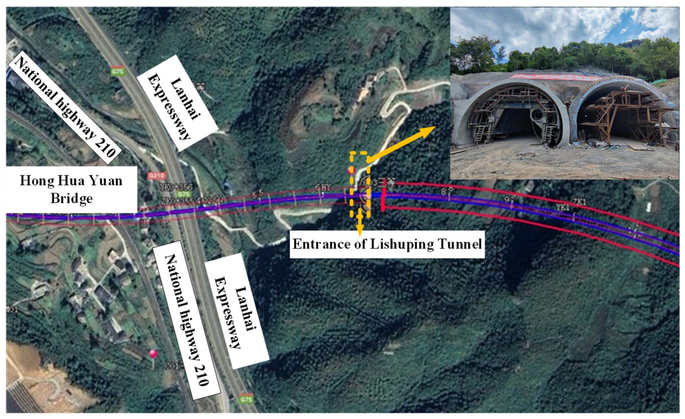
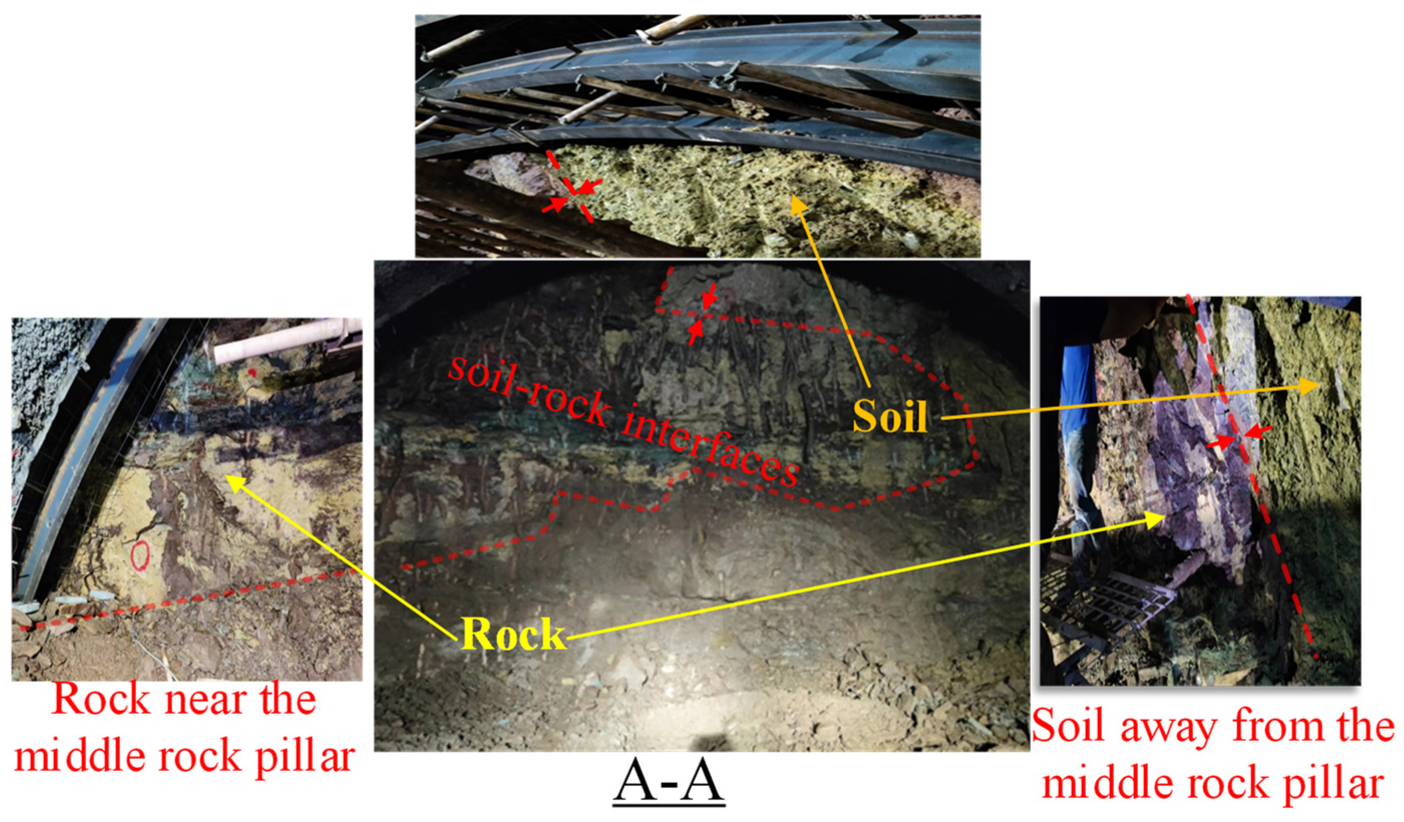
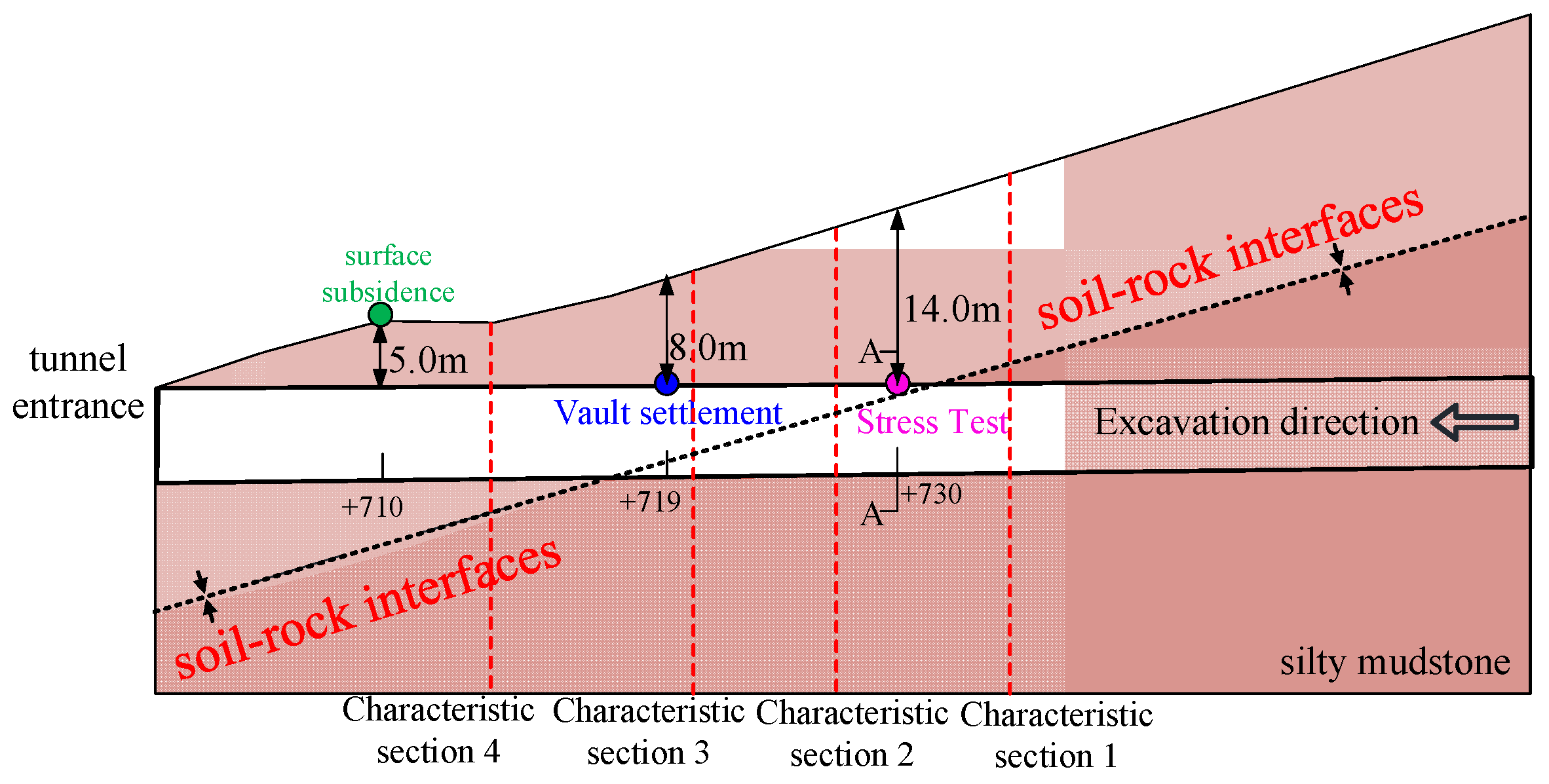
2.1. Project Background

Guizhou Tongxin Expressway Li Shuping Tunnel is a two-line separated tunnel, with a total length of about 1402 m and a maximum burial depth of about 197 m. The location of the tunnel and the topography of the tunnel entrance are shown in Figure 1. The tunnel was excavated in one direction with a distance of 22.3 m at the exit end and 4.9 m at the entrance, and the minimum thickness of the middle rock pillar was 0.6 m. The tunnel entrance section is a composite weak stratum of upper soil and lower rock, with brownish-yellow plasticized powdery silty clay and strongly weathered silty mudstone in the upper part, and grayish-white and brown medium-weathered silty mudstone in the lower part, as shown in Figure 2. When the left line tunnel (leading tunnel) was constructed to near section A-A (ZK0+730), the soil-rock interface was completely revealed, as shown in Figure 3. The rock layer on the palm face gradually changes from light-colored and tawny silty clay on the right side to strongly weathered silty mudstone on the side of the middle rock column, and the soil-rock interface on the right side extends to the foot of the arch.

2.2. Construction and Automation Monitoring Program

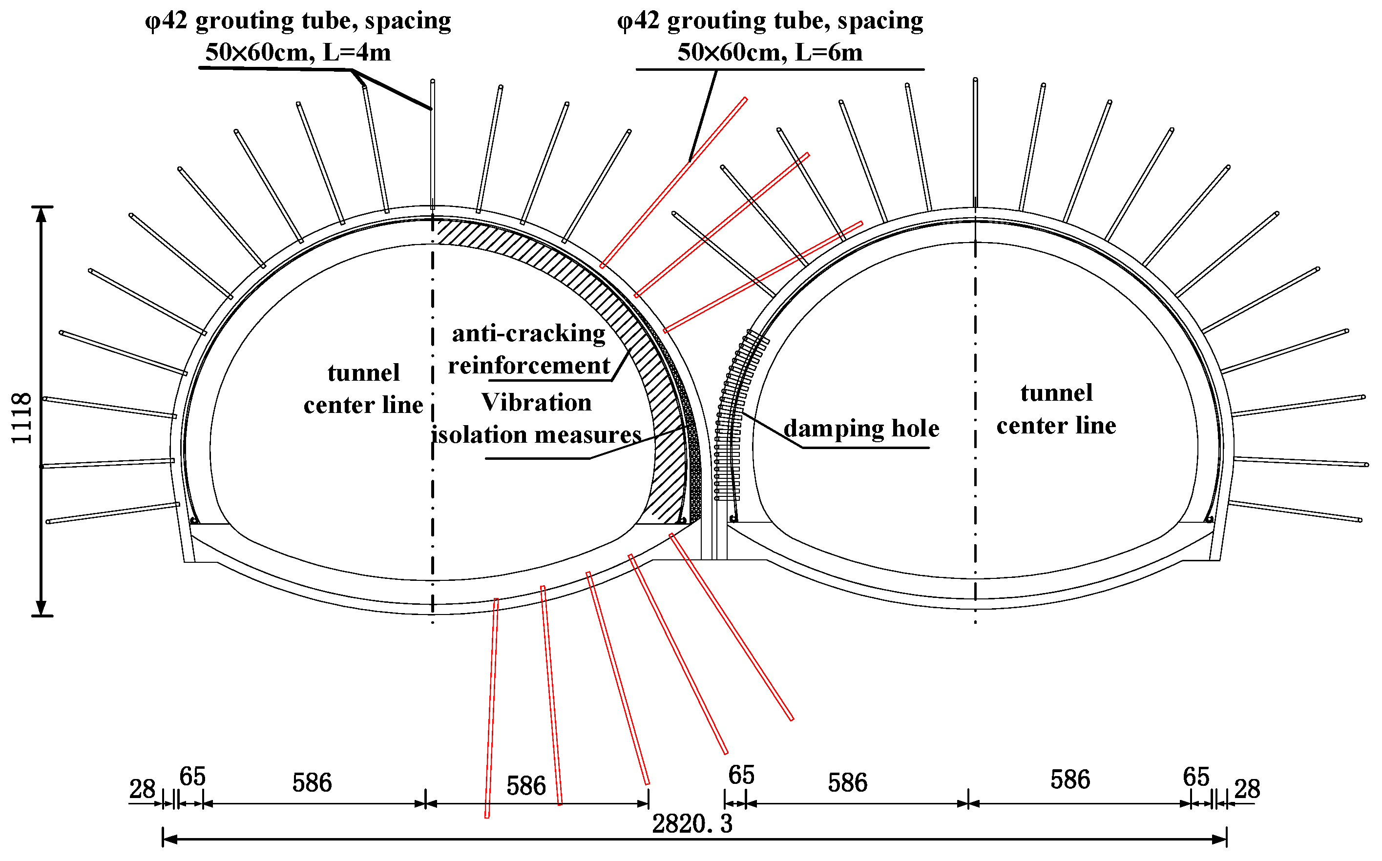
2.2.1. Construction and Support Parameters

The tunnel was excavated by the three-step method, with a single tunnel span of 14.1 m. The section of ZK0+705~ZK0+880 of the leading tunnel belongs to the section with super-small clear distance, and the profile clear distance of 2.5 m was gradually reduced to 0.6 m. During construction, grouting was used to reinforce the middle rock column when its thickness was 2.5~1.0 m. C25 shotcrete was used to replace the middle rock column when the thickness of the column was 1.0~0.6 m. The initial support adopted an I20 steel frame with 50 cm spacing, double-layer φ6 steel mesh, C25 shotcrete with 28 cm thickness, and φ42 grouted anchors with 4 m length; C30 reinforced concrete with a thickness of 65 cm was used for the secondary lining, and encryption of hooked reinforcement on the side of the middle rock column of the tunnel was excavated before the setting of anti-cracking reinforcement mesh. The arch waist and inverted arch on the middle rock column side of the tunnel excavated first were reinforced by 6 m-long φ42 grouting pipes, as shown in Figure 4.

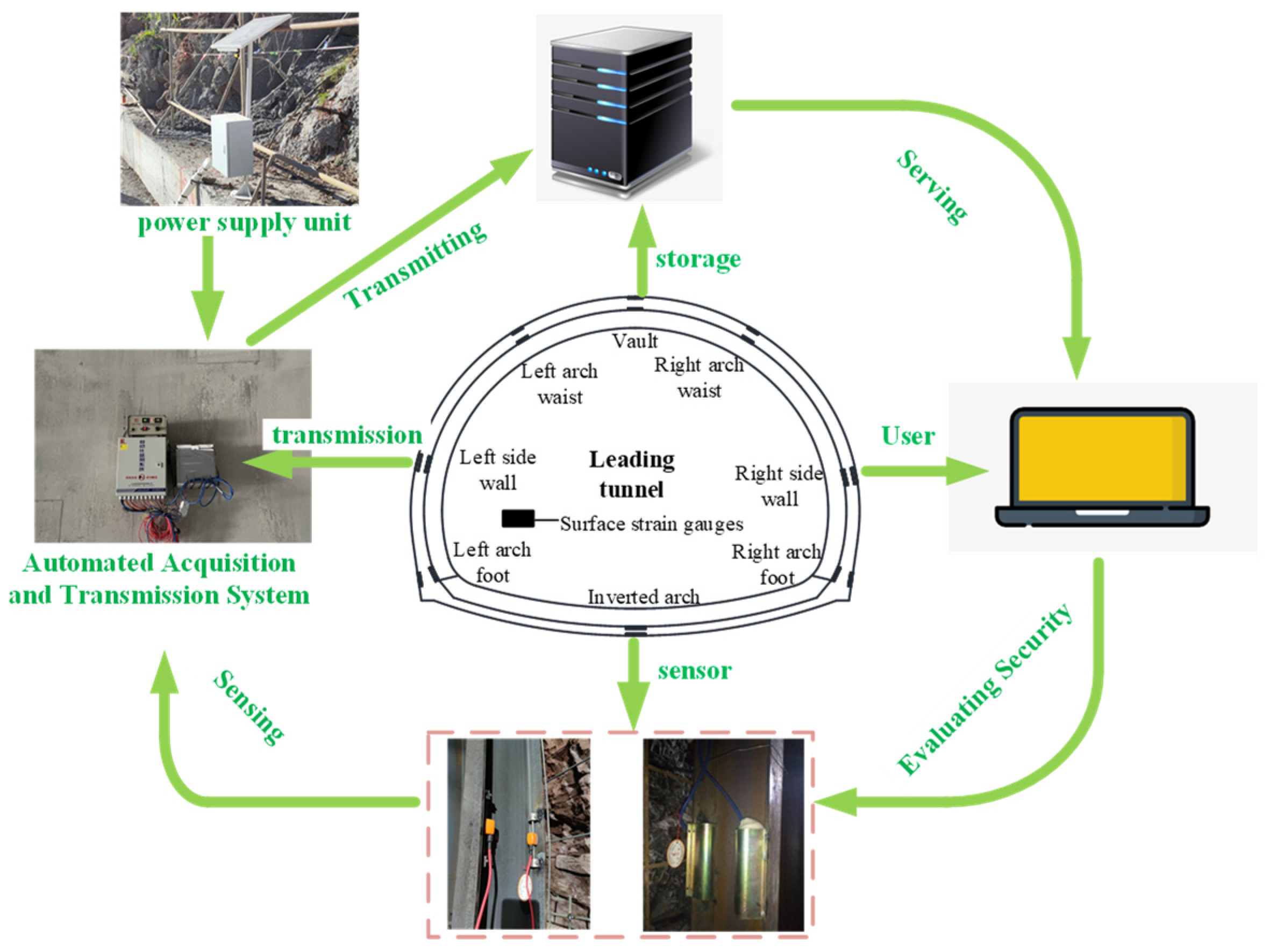
2.2.2. Automated Monitoring and Acquisition System

The automated monitoring and acquisition system is used to monitor the bearing status of the tunnel support structure, so as to evaluate whether the tunnel structure is safe or not. A stress monitoring system has been installed in four cross-sections of the Li Shuping tunnel to understand the safety and long-term stability of the support structure during tunnel construction and operation. The acquisition system consists of sensors, automated acquisition modules, signal transmission systems, power supply systems and server terminals, and the workflow of measurement point locations and automated acquisition equipment is shown in Figure 5.

2.2.3. Deformation and Stress Test Program

Considering the structural force characteristics and geological conditions of the ultra-small clearance tunnel, typical sections were selected in the leading tunnel for the internal force of the steel frame, vault settlement and ground settlement field tests. The section mileages were as follows: ZK0+730 for monitoring the internal force of the primary steel arch; ZK0+719 near the soil-rock interface of the tunnel entrance for monitoring the deformation of the surrounding rock inside the tunnel; ZK0+710 at the section of the tunnel entrance for monitoring the ground settlement.
Primary steel arch strain: monitoring section mileage ZK0+730, burial depth of about 14.0 m, thickness of the middle rock column 0.85 m. The geology of the palm face was complex: brownish-yellow silty mudstone at the arch waist near the medium rock column, and brownish-yellow strongly weathered silty mudstone at the arch foot and inverted arch; light and brownish-yellow powdery silty clay layers far from the lateral arch waist of the middle rock column (see Figure 3).
Vault settlement: the monitoring section is ZK0+719, the burial depth was about 7.0 m, and the thickness of the middle rock column was 0.72 m. The actual soil-rock interface was located at the invert-arch, where the tunnel superstructure crossed the soil stratum and the invert-arch crossed the rock stratum.
Ground settlement: monitoring section mileage ZK0+710, burial depth of about 5.0 m, thickness of the middle rock column 0.6 m. The actual soil-rock interface was located underneath the tunnel, and the tunnel completely crossed the soil stratum.

3. Field Test

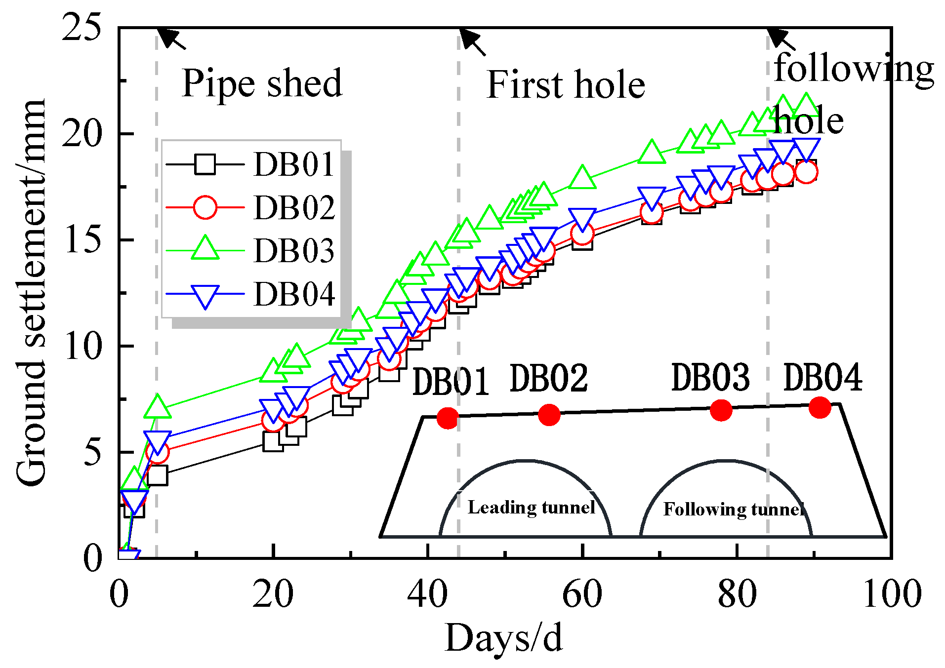
3.1. Ground Settlement

Figure 6 shows the settlement time curve of ground measurement points. The settlement process is roughly divided into four stages: advanced support, leading tunnel excavation, continuous growth, and following tunnel excavation. There was a rapid increase in ground settlement in the early period (0~3 d) due to the influence of advanced pipe shed construction; in the excavation stage of the leading tunnel (20~42 d), when the palm surface was close to the test section, the ground settlement of the first tunnel kept growing; as the palm face of the back row cave approached the test section, it entered the continuous growth section and the section affected by the construction of the following tunnel (42~82 d). In addition, the construction of the following tunnel exacerbated the ground settlement. The final displacement of measurement points DB03 and 04 was greater than DB01 and 02, and the final average settlement of the ground of the following tunnel was about 20.3 mm, which was greater than the average settlement of the first tunnel of 18.3 mm.

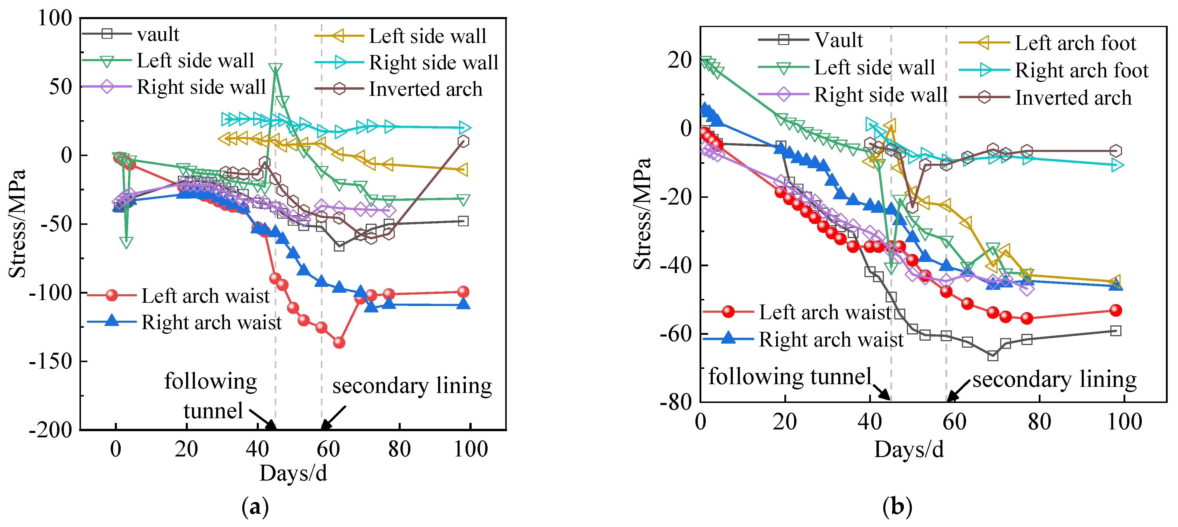
3.2. Time Variation of Stress in Primary Support Steel Frame

The stress-time curves of the measured points at the inner (outer) flanges of the primary supported steel arch are shown in Figure 7. From the outer flange (Figure 7a), it can be seen that the stress underwent a process of increasing and decreasing. As an example, the compressive stress on the outer side of the left arch waist (near the middle rock column) increased from 54.5 MPa to 136.6 MPa when the palm surface of the following tunnel approached the test section, an increase of about 1.5 times; after the reinforcement of the middle rock column and the application of the secondary lining, the stress was stabilized at 102.0 MPa, with a reduction of about 25% from the peak stress. There are two reasons why the curve increases and decreases: on the one hand, the weak surrounding rock and the weak middle rock column in this section led to the left arch waist being greatly affected by the excavation of the following tunnel, while on the other hand, the secondary lining of the first tunnel and the support of the later tunnel improved the stress on the primary steel frame and provided radial restraint, so the stabilizing stress of the left arch waist was much lower than the peak stress.
In addition, the stability of the surrounding rock also has a more obvious effect on the primary support force. At the right arch waist (further away from the middle rock column) of the outer flange (Figure 7a), the compressive stress increased from 56.4 MPa to about 109.0 MPa when the palm surface of the post-excavation tunnel approached the test section, an increase of about 1.9 times. This measurement point is located in a powdery clay soil, and the strength and stability of the surrounding rock is poor, resulting in a large increase in stress. The left sidewall and the foot of the left arch are affected by the weak blasting excavation of the following tunnel with brief fluctuations, and then return to stability, while the rest of the points are affected by the excavation of the following tunnel with a small increase to a stable value.
The stress variation of the measurement points in the soil layer is the main one. It can also be seen from Figure 7 that the locations with larger stress stability values of the steel arch in this test section are the vault and the left and right arch waist, and the size order is the right arch waist located in the soil layer and far from the side of the middle rock column, the left arch waist located in the middle rock column side of the rock layer, followed by the vault located in the rock layer. The magnitude of stress values shows that during the construction of tunnels containing soil-rock interface, the arch waist located in the soil layer far from the middle rock column side is more dangerous than the arch waist in the rock layer on the middle rock column side, and the construction should pay attention to the reinforcement of the soil layer side.

3.3. Measured Bending Moment Distribution of Primary Support Steel Frame

The measured bending moment of each section is calculated by Equation (1) for the stresses on the inner and outer flanges of the stabilized steel arch in Figure 7:
M = ( σ 1 σ 2 ) I 2 y
where: M is the measured bending moment; σ1 and σ2 are the stresses on the outer and inner flanges of the steel arch, respectively; I is the I20 steel frame moment of inertia; and y is the distance of the measurement point from the neutral axis of the steel arch.
The primary support bending moment diagram is shown in Figure 8. The moment diagram is basically symmetrically distributed, with both sides of the arch waist to bear the slip load on both sides of the shallow buried tunnel; the vault is extruded by both sides of the arch waist and bent outward. Due to the weak soil on the side furtherest away from the middle rock column, the force on this side of the arch waist is also greater.

4. Analysis of the Influence of Soil-Rock Partition Location on Tunnel Structure

This section may be divided by subheadings. It should provide a concise and precise description of the experimental results, their interpretation, as well as the experimental conclusions that can be drawn.

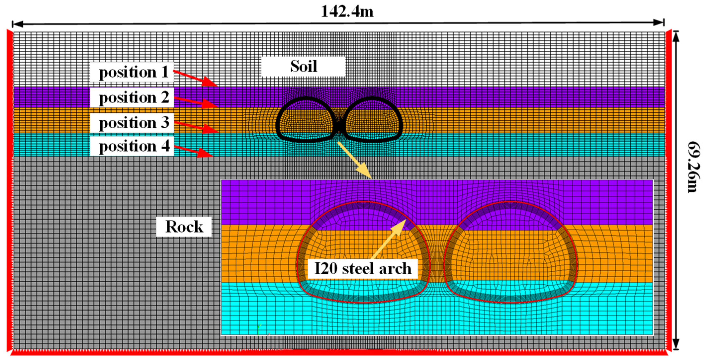
4.1. Numerical Model

Since the failure mechanisms of complex strata are different from those observed for a single lithology, it is necessary to study composite strata [35] to observe the effect of the soil-rock interface on the deformation of the surrounding rock and the initial support force of the tunnel. Combined with the geological situation of the Li Shuping tunnel, according to the relative relationship between the soil-rock interface and the tunnel, it can be divided into four positions: the interface above the tunnel (characteristic section 1), the interface inside the tunnel (characteristic section 2), the interface inside the tunnel (characteristic section 3) and the interface below the tunnel (characteristic section 4), as shown in Figure 2. The finite element model for the four positions is shown in Figure 9. The model was built using DIANA, which is a finite element software. The model length is 142.4 m, width is 69.2 m, the soil-rock interface in the model is assumed to be horizontal, and the thickness of the middle rock column is taken as 1.0 m. The rock and soil follow the Mohr-Coulomb strength criterion, the I20 steel arch follows the von Mises yield criterion, and the concrete follows the Total Strain crack model. The lower boundary range of the model is taken as three times the diameter of the tunnel, the upper surface is free, and the rest of the boundary is taken as normal constraint. Geotechnical material calculation parameters are shown in Table 1.

4.2. Numerical Simulation of Working Conditions

The specific simulations of the construction stages are as follows: initial ground stress equilibrium under self-weight; excavation and support of the upper step of the left tunnel; excavation and support of the middle step of the left tunnel; excavation and support of the lower step of the left tunnel; application of the secondary lining of the left tunnel. The right tunnel is excavated in the same way and the steps will not be repeated.
According to the four relative positions of soil-rock interface and tunnel in Figure 9 and the actual burial depth, 20 working conditions are set (see Table 2). Position 1~4 distributions are expressed as: soil-rock interface located 2 m above the vault, arch waist, arch foot, and 2 m below the tunnel bottom, containing the change of interface position of the tunnel from the rock construction to the soil layer. The four positions correspond exactly to the four characteristic sections in Figure 2. According to the burial depth range in Figure 2, the five burial depth cases are 5.0 m, 8.0 m, 10.0 m, 12.0 m and 14.0 m. For example, Case 8 can indicate a burial depth of 8 m and the tunnel crossing a soil stratum.

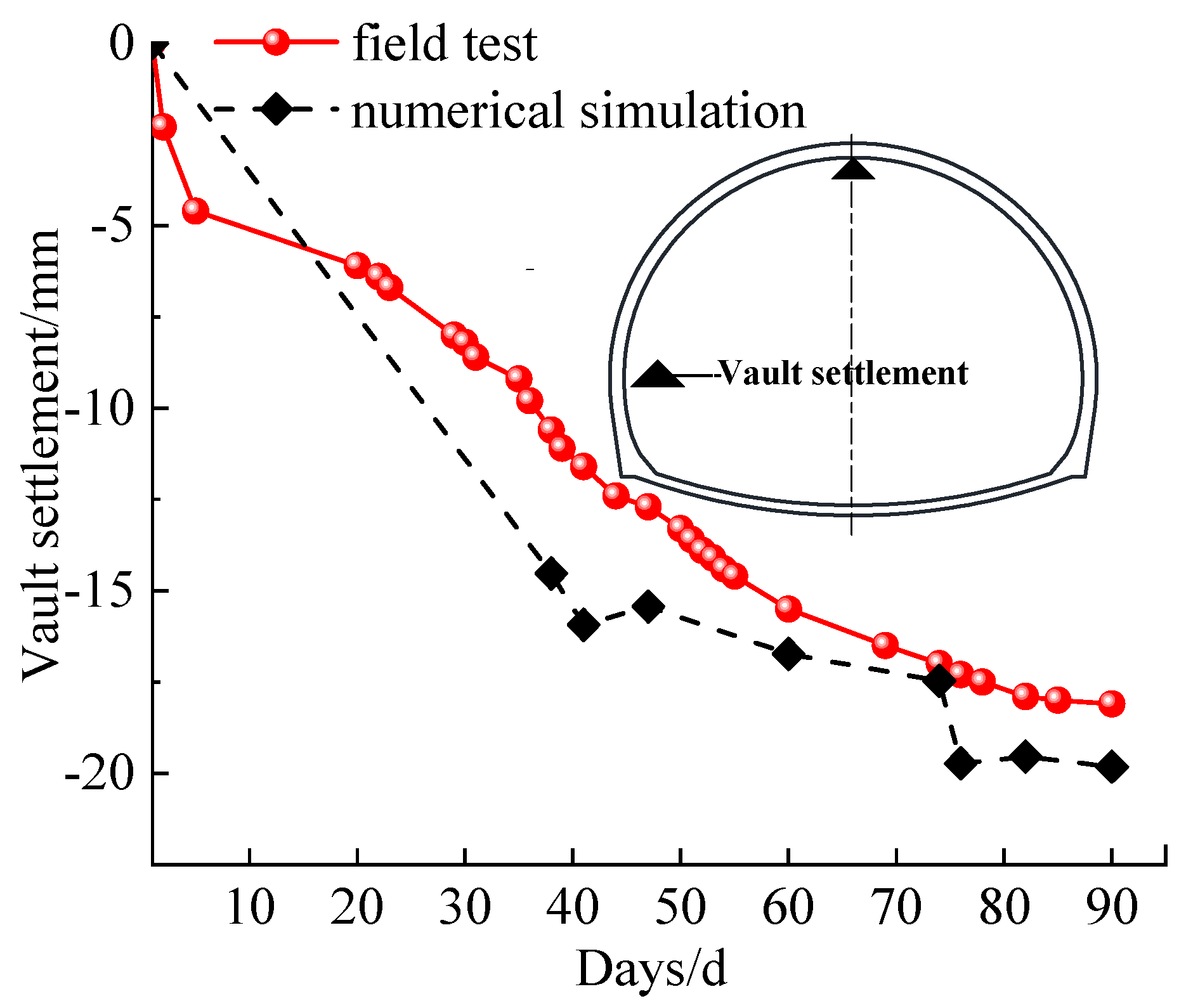
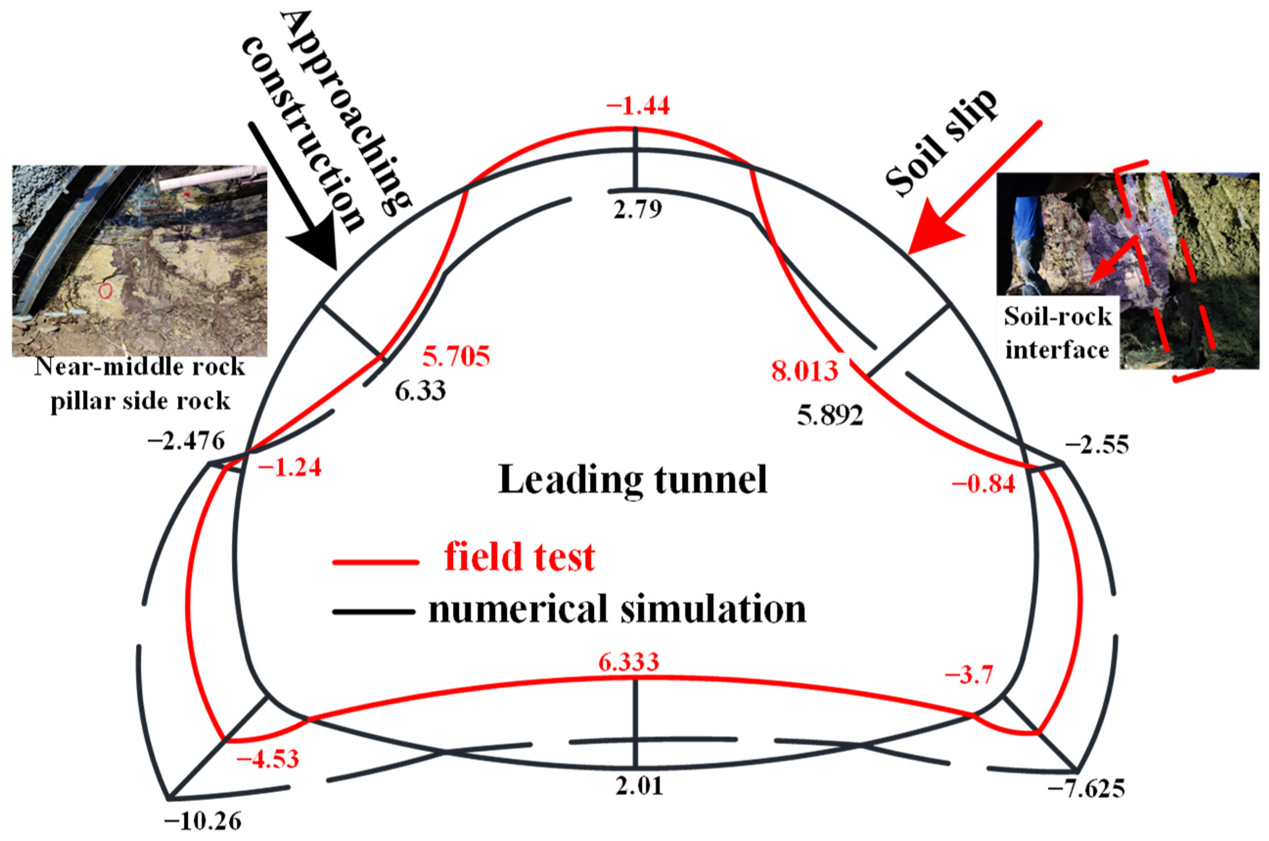
4.3. Model Reasonableness Verification

Section ZK0+719 is buried at a depth of 8 m, and the actual soil-rock interface is located at the bottom of the inverted arch, which is consistent with the numerical calculation of working condition 8. Therefore, the settlement time curve of the vault of the left tunnel (leading tunnel) in working condition 8 is selected for comparison with this section, as shown in Figure 10. As can be seen from Figure 10, the time course curve trends of numerical simulation and field monitoring data are basically consistent, and the settlement of the vault of the leading tunnel experiences three stages of rapid growth in the early stage, slow growth in the middle stage, and basic stability in the late stage. After the completion of the backline cave support, the numerical simulation and the field measurement of the vault settlement are −19.8254 mm and −18.1 mm, respectively, and the difference between the vault settlement after the completion of the following tunnel support and the vault settlement after the completion of the first tunnel support in the two cases are −3.093 mm and −2.6 mm, respectively, which account for 15.6% and 14.36% of the vault settlement of the first cave after the completion of the following tunnel support, respectively. It can be considered that under the numerical simulation and the field measurement, the influence of the rear tunnel on the settlement of the vault of the first tunnel is comparable, which verifies the reasonableness of the numerical simulation. The ZK0+710 section is consistent with the working condition 4, and the final value of the ground settlement of the working condition 4 is selected to compare with this section, as shown in Table 3. The errors of the left and right tunnels are 0.7% and 7.39%, which further verifies the reasonableness of the numerical simulation.

4.4. Analysis of Calculation Results

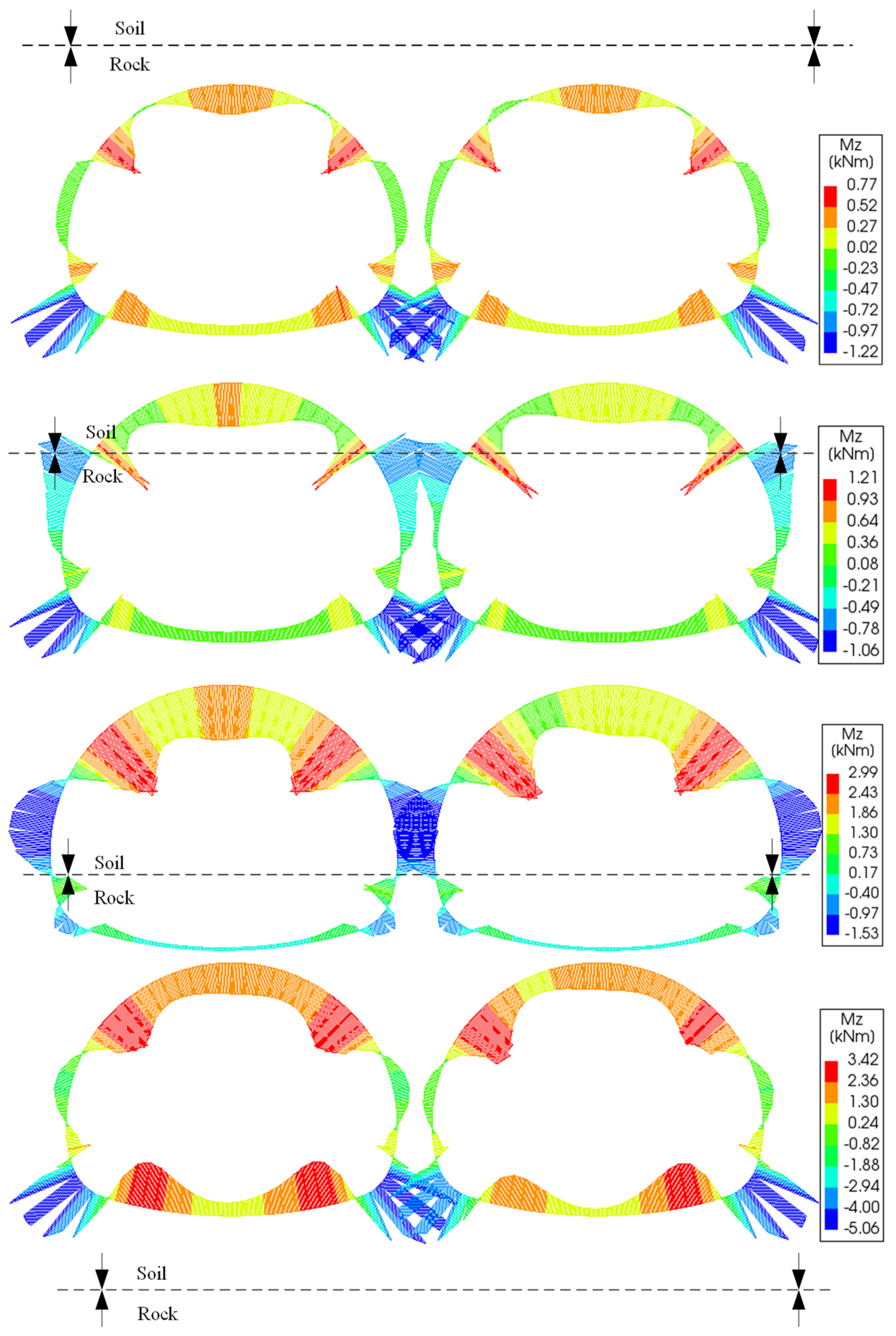
4.4.1. Primary Support Force Characteristics

In the case of shallow burial, the burial depth has a greater influence on the bending moment of the tunnel structure. Take the soil-rock interface position 2, which is most affected by the burial depth—as an example, see Figure 11. It shows that at the same soil-rock interface position, the bending moment of the vault and arch waist of the first tunnel increases with the increase in burial depth, and the value and growth rate of the bending moment of the arch waist on the side close to the middle rock pillar are higher than those away from the middle rock pillar, and the increases are 277%, 175.8%, and 176.9%, respectively. The reason for this, with reference to the theory of Karl von Terzaghi, is that the pressure acting on the top of the tunnel and the slip load on both sides increases with the depth of burial.
The position of the soil-rock interface has a significant effect on the initial support bending moment, and the shallower the burial depth, the greater the effect. Taking Figure 12 of the bending moment at different soil-rock interface positions at a burial depth of 5 m as an example, it shows that as the soil-rock interface moves down from position 1 at the top of the tunnel to position 4 at the bottom of the tunnel, the bending moment values of the vault, and the left and right arch waist, increase due to the vertical load of the overlying soil and the sliding load on both sides, with increases of 325%, 313%, and 325.5%, respectively. The construction direction of the Li Shuping tunnel is exactly the process of changing position 1 to position 4. The analysis of the change of the initial support moment with the position of the soil-rock interface indicates that special attention should be paid to the reinforcement and strengthening of the vault and the left and right arch waist during the construction process.
The effect of the soil-rock interface position on the initial support moment is greater than the effect of proximity construction. The monitoring section (ZK0+730) is more consistent with working condition 20, so the working condition 20 bending moment is compared with the measured bending moment map (see Figure 13). As can be seen from Figure 13, the two bending moments are basically symmetrically distributed. Under the numerical simulation conditions, it is known from von Terzaghi’s theory that the shallow buried tunnel vault and arch waist are subjected to larger soil vertical pressure and slip load, respectively, and the overall inward bending, and the middle rock pillar side, is affected by the proximity construction; the bending moment value is also slightly larger than that away from the middle rock pillar side. Due to the fact that the vault and arch waist on the side of the actual palm face of the middle rock pillar are rock, and the arch waist away from the side of the middle rock pillar is soil, which bends outward under the action of the slip load on both sides of the arch waist, and the vault bends outward, the measured moment of the arch waist in the soil is larger than that of the arch waist in the rock affected by the proximity construction on the side of the rock pillar, and the comprehensive geology of the palm surface and numerical simulation show that the position of the soil-rock interface has a greater influence on the force of the support structure than that of the proximity construction.

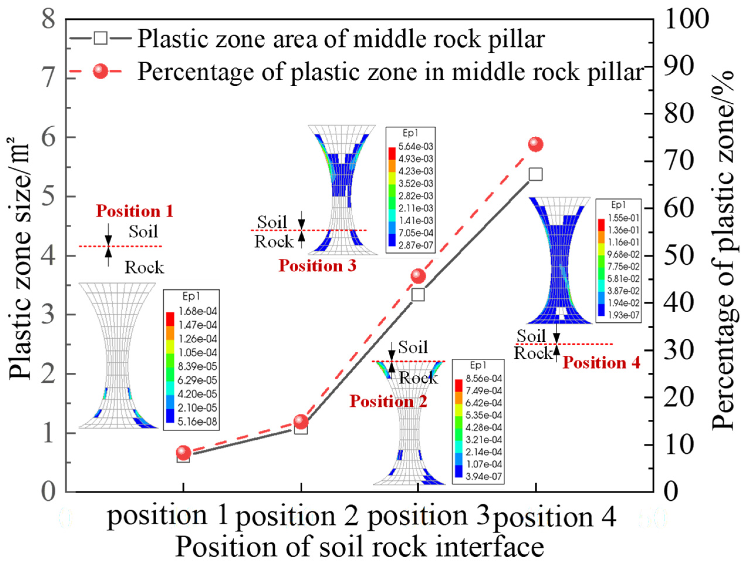
4.4.2. Variation of the Plastic Zone in the Middle Rock Pillar

The soil-rock interface and the rock pillar in the soil are the main damaged parts. Take the plastic zone of the middle rock pillar under the position of each soil-rock interface at the burial depth of 14 m as an example, as shown in Figure 14. Figure 14 shows that with the downward movement of the soil-rock interface, the plastic zone of the middle rock pillar is mainly located near the soil-rock interface and part of the soil middle rock pillar, until the plastic zone of the soil middle rock column is penetrated; at the same time, the area of the plastic zone of the middle rock pillar and the percentage of the plastic zone of the middle rock pillar also increase with the downward shift of the soil-rock interface position. Therefore, the construction of the Li Shuping tunnel uses C25 shotcrete to replace the soil in the rock pillar after expansion, and uses shotcrete to replace the broken part of the rock pillar at the bottom and arch foot grouting to supplement the reinforcement.

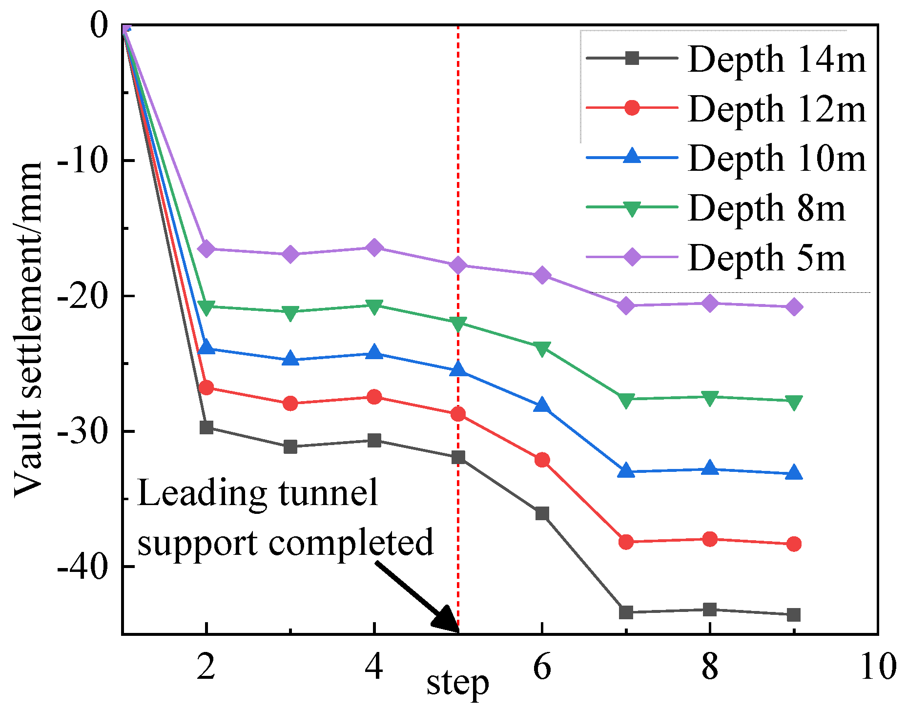
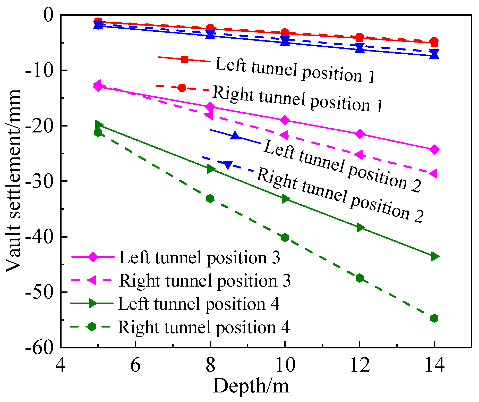
4.4.3. Effect of Burial Depth on Surrounding Rock Deformation

When the tunnel crosses the soil stratum, the settlement of the vault of the first tunnel is affected by the excavation of the later cave and increases with the depth of burial. When the soil-rock interface is located at position 4, the settlement curve of the tunnel vault of the first tunnel under different burial depths is analyzed for the influence law of proximity construction, as shown in Figure 15. From Figure 15, it can be seen that the settlement values of the vault after the completion of the support of the following tunnel under each burial depth increase with the depth of burial, which are −20.83 mm, −27.76 mm, −33.15 mm, −38.33 mm, and −43.55 mm, respectively. Excavation of the following tunnel will cause an increase in the settlement of the vault of the first tunnel. The difference in the vault of the first tunnel after the completion of the support of the following cave and the first cave is called the proximity construction influence value of the second cave, and the ratio of the proximity construction influence value to the vault settlement of the first cave after the completion of the support of the second cave is called the proximity construction influence degree. The proximity construction influence values and proximity construction influence degrees for the five burial depths are −3.09 mm, −5.80 mm, −7.63 mm, −9.60 mm, −11.62 mm and 14.85%, 20.90%, 23.01%, 25.05%, and 26.29%, respectively.
The variation of vault settlement with burial depth after the completion of left and right tunnel supports under different soil-rock interface positions is shown in Figure 16. The soil-rock interface is located in positions 1 and 2, and the final vault settlement of the first tunnel is greater than that of the second tunnel under each burial depth condition, but the difference between the two is small, so the construction should focus on the impact of the excavation of the second cave on the first cave. When the soil-rock interface is located in two cases, positions 3 and 4, the final arch settlement value of the backward cave is larger than the first cave under each burial depth condition, and the difference increases with the increase in burial depth, indicating that when the tunnel superstructure or tunnel structure is all located in the soil stratum, the construction should pay attention to the control of excavation deformation of the following tunnel, in addition to the influence of the first tunnel by the proximity construction.

5. Discussion

When the soil-rock interface moves from the top of the tunnel (position 1) to the bottom of the tunnel (position 4), especially when the soil-rock interface is at position 3 and position 4, the final vault settlement of the first tunnel will be smaller than the vault settlement of the second tunnel. The reason is that the soil strength is weak, so the excavation of the first tunnel will immediately cause the soil at the second tunnel to slide to the side of the first tunnel, and when the second tunnel is excavated, the soil is disturbed again, which intensifies the settlement.
It is generally believed that when a double tunnel structure is located in a single homogeneous stratum, the side of the first tunnel near the middle pillar will be affected by the proximity construction and is the more dangerous area. This is confirmed by the fact that the bending moment on the side near the middle pillar (6.33 kNm) in the numerical simulation for Case 20 is greater than that on the other side (5.892 kNm). However, the monitoring data showed that the bending moment on the side near the middle rock pillar (5.705 kNm) was smaller than that on the side away from the middle rock pillar (8.013 kNm). The reason is that the side near the middle rock column is rock, which still has a certain strength and stability even if it is affected by the proximity construction. The side away from the middle rock column is soil, which has poor strength and stability and is susceptible to slippage by excavation.

6. Conclusions

(1) The field measurement shows that the stress change of the steel arch frame of the first tunnel is affected by both the proximity construction and the stability of the surrounding rock.
(2) The numerical simulation results show that the position of the soil-rock interface has a significant influence on the initial support force of the first tunnel, and the bending moment increases with the downward movement of the soil-rock interface. The downward movement of the soil-rock interface at the same burial depth will lead to an increase in the bending moment of the vault and the arch waist of the first tunnel, and the value and growth of the arch waist bending moment on the side close to the middle rock pillar are higher than the arch waist on the side furtherest from the middle rock pillar.
(3) The impact of soil-rock interface location on the initial support moment of the first tunnel is greater than the impact of tunnel proximity construction. Numerical simulation and field monitoring of the bending moment results show that the position of the soil-rock interface has a greater effect on the force of the initial support structure than that of the proximity construction.
(4) Vault settlement and ground settlement are more sensitive deformation features. Numerical simulation and field measurement results show that when the soil-rock interface is located below the foot of the arch, the vault settlement and the surface settlement of the lateral cave will be larger than that of the first cave, so monitoring should be strengthened during construction.
Due to the assumption in this paper that the soil-rock interface is horizontal, it does not exactly match with the complex geological conditions in engineering practice. To make the study more representative, a combination of theoretical study and numerical simulation will be used in the future to study more complex situations when the soil-rock interface is inclined.

Author Contributions

Conceptualization and methodology, X.Z. (Xuemin Zhang) and X.Z. (Xianshun Zhou); software, D.F.; numerical simulations and data curation, D.F. and X.Z. (Xianshun Zhou); field monitoring, D.F. and Y.H.; writing—original draft preparation, D.F. and X.Z. (Xuemin Zhang); writing—review and editing, X.Z. (Xuemin Zhang), D.F., X.Z. (Xianshun Zhou) and Y.H.; funding acquisition, X.Z. (Xuemin Zhang) and Y.H. All authors have read and agreed to the published version of the manuscript.

Funding

This research was funded by the National Natural Science Foundation of China (No. 51978671), Postgraduate research and innovation project of Central South University (No. 1053320213140).

Data Availability Statement

The data used to support the findings of this study are available from the corresponding author on reasonable request.

Conflicts of Interest

The authors declare no conflict of interest.

References

  1. Lu, A.Z.; Zhang, L.Q. Complex Function Method on Mechanical Analysis of Underground Tunnel; Science Press: Beijing, China, 2007. [Google Scholar]
  2. Chen, Z.Y. Analytical Method of Rock Mechanics Analysis; China Coal Industry Publishing House: Beijing, China, 1994. [Google Scholar]
  3. Lu, A.; Xu, Z.; Zhang, N. Stress analytical solution for an infinite plane containing two tunnels. Int. J. Mech. Sci. 2017, 128, 224–234. [Google Scholar] [CrossRef]
  4. Zeng, X.; Lu, A.; Zhang, N. Analytical stress sol ution for an infinite plate containing two oval tunnels. Eur. J. Mech.-A/Solids 2018, 67, 291–304. [Google Scholar] [CrossRef]
  5. Wang, H.N.; Zeng, G.S.; Utili, S.; Jiang, M.J.; Wu, L. Analytical solutions of stresses and displacements for deeply buried twin tunnels in viscoelastic rock. Int. J. Rock Mech. Min. Sci. 2017, 93, 13–29. [Google Scholar] [CrossRef]
  6. Chen, F.; Lin, L.; Li, D. Analytic solutions for twin tunneling at great depth considering liner installation and mutual interaction between geomaterial and liners. Appl. Math. Model. 2019, 73, 412–441. [Google Scholar] [CrossRef]
  7. Yanqing, L.; Shihang, Z.; Rusui, L.; Rongtian, M. Experimental study on mechanical characteristics of twin tunnels with small spacing. Chin. J. Rock Mech. Eng. 2000, 19, 590–594. [Google Scholar]
  8. Gong, J.W.; Xia, C.C.; Lei, X.W. Calculation and monitoring analysis of surrounding rock pressure of shallow buried small clearance tunnel. Chin. J. Rock Mech. Eng. 2010, 29 (Suppl. S2), 4139–4145. [Google Scholar]
  9. Mingqing, X.; Chen, X. Discussion on the representative value of surrounding rock pressure of deep buried small clearance tunnel. J. Railw. Eng. Soc. 2020, 37, 83–89. [Google Scholar]
  10. Jia, L. Calculation method and stress characteristics of surrounding rock in small clearance tunnel with weak geology. Tunn. Constr. (Chin.-Engl.) 2021, 41 (Suppl. S1), 174–180. [Google Scholar]
  11. Fang, Q.; Tai, Q.; Zhang, D.; Wong, L.N.Y. Ground surface settlements due to construction of closely-spaced twin tunnels with different geometric arrangements. Tunn. Undergr. Space Technol. 2016, 51, 144–151. [Google Scholar] [CrossRef]
  12. Acun, S.; Bilgin, N.; Erboylu, U. Contribution on the understanding of EPB-TBM drives in complex geologic structures. Tunn. Undergr. Space Technol. 2021, 107, 103646. [Google Scholar] [CrossRef]
  13. Fang, H.; Zhang, D.; Fang, Q.; Wen, M. A generalized complex variable method for multiple tunnels at great depth considering the interaction between linings and surrounding rock. Comput. Geotech. 2021, 129, 103891. [Google Scholar] [CrossRef]
  14. Shivaei, S.; Hataf, N.; Pirastehfar, K. 3D numerical investigation of the coupled interaction behavior between mechanized twin tunnels and groundwater—A case study: Shiraz metro line 2. Tunn. Undergr. Space Technol. 2020, 103, 103458. [Google Scholar] [CrossRef]
  15. Rahaman, O.; Kumar, J. Stability analysis of twin horse-shoe shaped tunnels in rock mass. Tunn. Undergr. Space Technol. 2020, 98, 103354. [Google Scholar] [CrossRef]
  16. Ghaboussi, J.; Ranken, R.E. Interaction between two parallel tunnels. Int. J. Numer. Anal. Methods Geomech. 1977, 1, 75–103. [Google Scholar] [CrossRef]
  17. Costamagna, E.; Oggeri, C.; Vinai, R. Damage and contour quality in rock excavations for quarrying and tunnelling: Assessment for properties and solutions for stability. In IOP Conference Series: Earth and Environmental Science; IOP Publishing: Bristol, UK, 2021; Volume 833, p. 012137. [Google Scholar]
  18. Shirinabadi, R.; Moosavi, E. Twin tunnel behavior under static and dynamic loads of Shiraz metro, Iran. J. Min. Sci. 2016, 52, 461–472. [Google Scholar] [CrossRef]
  19. El Omari, A.; Chourak, M.; Echebba, E.M.; Cherif, S.E.; Navarro Ugena, C.; Rougui, M.; Chehade, F.H.; Fernández, F.L.; Chaaraoui, A. Numerical analysis of twin tunnels lining under different seismic conditions. Infrastructures 2021, 6, 29. [Google Scholar] [CrossRef]
  20. Guijun, W.; Chundu, L.; Switzerland, G.; Junhua, H.; Qi, Z. Excavation deformation and stress analysis of soft interlayer section of shallow buried small clearance tunnel. J. Highw. Transp. Sci. Technol. 2022, 39, 131–138. [Google Scholar]
  21. Jingang, L. Study on the Influence of Construction Sequence on Ultra-Small Clearance Cross Tunnel. Modern TunnelTechnology: 1–7. Available online: http://kns.cnki.net/kcms/detail/51.1600.U.20220309.1521.002.html (accessed on 17 November 2022).
  22. Yi, F. Model test study of large-span and small-clearance highway tunnel. Chin. J. Undergr. Space Eng. 2016, 12 (Suppl. S1), 18–23+31. [Google Scholar]
  23. Zhiyu, T.; Guojin, L.; Jinlong, Z.; Lian, W. Study on Failure Mode of Small Clear Distance Tunnel. Mod. Tunn. Technol. 2019, 56 (Suppl. S2), 202–208. [Google Scholar] [CrossRef]
  24. Ou, Y.; Tian, G.; Chen, J.; Chen, G.; Chen, X.; Li, H.; Liu, B.; Huang, T.; Qiang, M.; Satyanaga, A.; et al. Feasibility Studies on the Utilization of Recycled Slag in Grouting Material for Tunneling Engineering. Sustainability 2022, 14, 11013. [Google Scholar] [CrossRef]
  25. Zhenhu, Y.; Kai, W.; Kun, T.; Bin, L.; Wenjie, L. Study on stability and reinforcement scheme of rock column in shallow buried small clearance tunnel. J. Yangtze River Res. Inst. 2022, 39, 126–134. [Google Scholar]
  26. Li, P.X.; Chen, B.R.; Xiao, Y.X.; Feng, G.L.; Zhou, Y.Y.; Zhao, J.S. Rockburst and microseismic activity in a lagging tunnel as the spacing between twin TBM excavated tunnels changes: A case from the Neelum-Jhelum hydropower project. Tunn. Undergr. Space Technol. 2023, 132, 104884. [Google Scholar] [CrossRef]
  27. Fu, J.; Zhao, N.; Qu, Y.; Yang, J.; Wang, S. Effects of twin tunnel undercrossing excavation on the operational high speed railway tunnel with ballastless track. Tunn. Undergr. Space Technol. 2022, 124, 104470. [Google Scholar] [CrossRef]
  28. Zhou, Z.; Ding, H.; Miao, L.; Gong, C. Predictive model for the surface settlement caused by the excavation of twin tunnels. Tunn. Undergr. Space Technol. 2021, 114, 104014. [Google Scholar] [CrossRef]
  29. Qi-Xiang, Y.; Chuan, H.E.; Yong, Y.A.O. Study on construction characteristics and dynamic mechanical behavior of soft rock tunnel. Chin. J. Rock Mech. Eng. 2006, 25, 572–577. [Google Scholar]
  30. Kun, J.; Caichu, X. Monitoring measurement analysis of two-way eight-lane small clearance highway tunnel. Chin. J. Rock Mech. Eng. 2010, 29 (Suppl. S2), 3755–3761. [Google Scholar]
  31. Songtao, L.; Zhongsheng, T.; Wentao, D. Mechanical effect analysis of small clearance highway tunnel with extra la-rge section. China Civ. Eng. J. 2017, 50 (Suppl. S2), 292–296. [Google Scholar] [CrossRef]
  32. Yunliang, Z.; Changsheng, W.; Ping, L.; Fengxiang, L. Small clearance tunnel construction monitoring measurement and numerical analysis. J. Railw. Sci. Eng. 2011, 8, 50–53. [Google Scholar] [CrossRef]
  33. Ran, L.; Shengtao, W.; Dingli, Z.; Ping, C.; Honggui, P.; Ao, L. Control Mechanism and Engineering Application of Rock-interbed Tension Anchor in Small Clear Distance Tunnel. Rock Soil Mech. 2022, 43, 1865–1876. [Google Scholar] [CrossRef]
  34. Oggeri, C.; Oreste, P. Tunnel static behavior assessed by a probabilistic approach to the back-analysis. Am. J. Appl. Sci. 2012, 9, 1137. [Google Scholar]
  35. Greco, O.; Ferrero, A.M.; Oggeri, C. Experimental and analytical interpretation of the behaviour of laboratory tests on composite specimens. Int. J. Rock. Mech. Min. Sci. 1993, 30, 1539–1543. [Google Scholar] [CrossRef]
Figure 1. Location of the tunnel and topographic map of the tunnel entrance.
Buildings 13 00559 g001
Figure 2. Longitudinal view of the soil-rock interface at the tunnel entrance.
Buildings 13 00559 g002
Figure 3. Soil-rock interface of A-A face.
Buildings 13 00559 g003
Figure 4. Cross-sectional parameters (unit: cm).
Buildings 13 00559 g004
Figure 5. Monitoring points and automation system workflow.
Buildings 13 00559 g005
Figure 6. ZK0+710 surface subsidence time history graph.
Buildings 13 00559 g006
Figure 7. Stress-time curve of the steel arch at section ZK0+730: (a) Outer flange; (b) Inner flange.
Buildings 13 00559 g007
Figure 8. ZK0+730 measured bending moment (unit: kN·m).
Buildings 13 00559 g008
Figure 9. Position of soil-rock interface and finite element model of ultra-small clearance tunnel.
Buildings 13 00559 g009
Figure 10. Vault settlement time history curve.
Buildings 13 00559 g010
Figure 11. The bending moment of the leading tunnel in position 2 varies with the burial depth.
Buildings 13 00559 g011
Figure 12. Bending moment of different soil-rock interface positions at a buried depth of 5 m.
Buildings 13 00559 g012
Figure 13. Comparison of measured bending moment with numerical simulation (unit: kN·m).
Buildings 13 00559 g013
Figure 14. Plastic zone of the middle rock column at four soil-rock interface positions (depth: 14 m).
Buildings 13 00559 g014
Figure 15. Vault settlement of the leading tunnel at position 4 of the soil-rock interface with construction steps.
Buildings 13 00559 g015
Figure 16. Vault settlement at different soil-rock interface positions varies with burial depth.
Buildings 13 00559 g016
Table 1. Calculation material parameters.
MaterialsDensity
(kg·m−3)
Elastic Modulus (GPa)Poisson RatioCohesion
(Mpa)
Friction Angle (°)
Surrounding rock18001.20.350.1627
Silty clay18000.030.350.01620
C252200280.2//
Secondary lining2500300.2//
Table 2. Numerical simulation case table.
Depth/mPosition 1Position 2Position 3Position 4
5.01234
8.05678
10.09101112
12.013141516
14.017181920
Table 3. Case 4 and ZK0+710 measured surface settlement.
Case 4Field Test
Left tunnel18.3454 mm18.2 mm
Right tunnel19.6324 mm21.2 mm
Disclaimer/Publisher’s Note: The statements, opinions and data contained in all publications are solely those of the individual author(s) and contributor(s) and not of MDPI and/or the editor(s). MDPI and/or the editor(s) disclaim responsibility for any injury to people or property resulting from any ideas, methods, instructions or products referred to in the content.

