
Utilizing Low Yield Point Steel to Improve the Behavior of the I-Shaped Shear Links as Dampers


Abstract
1. Introduction
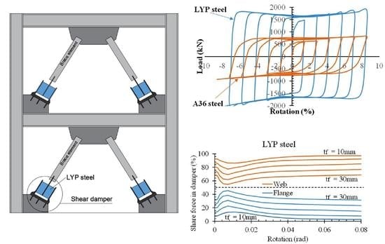
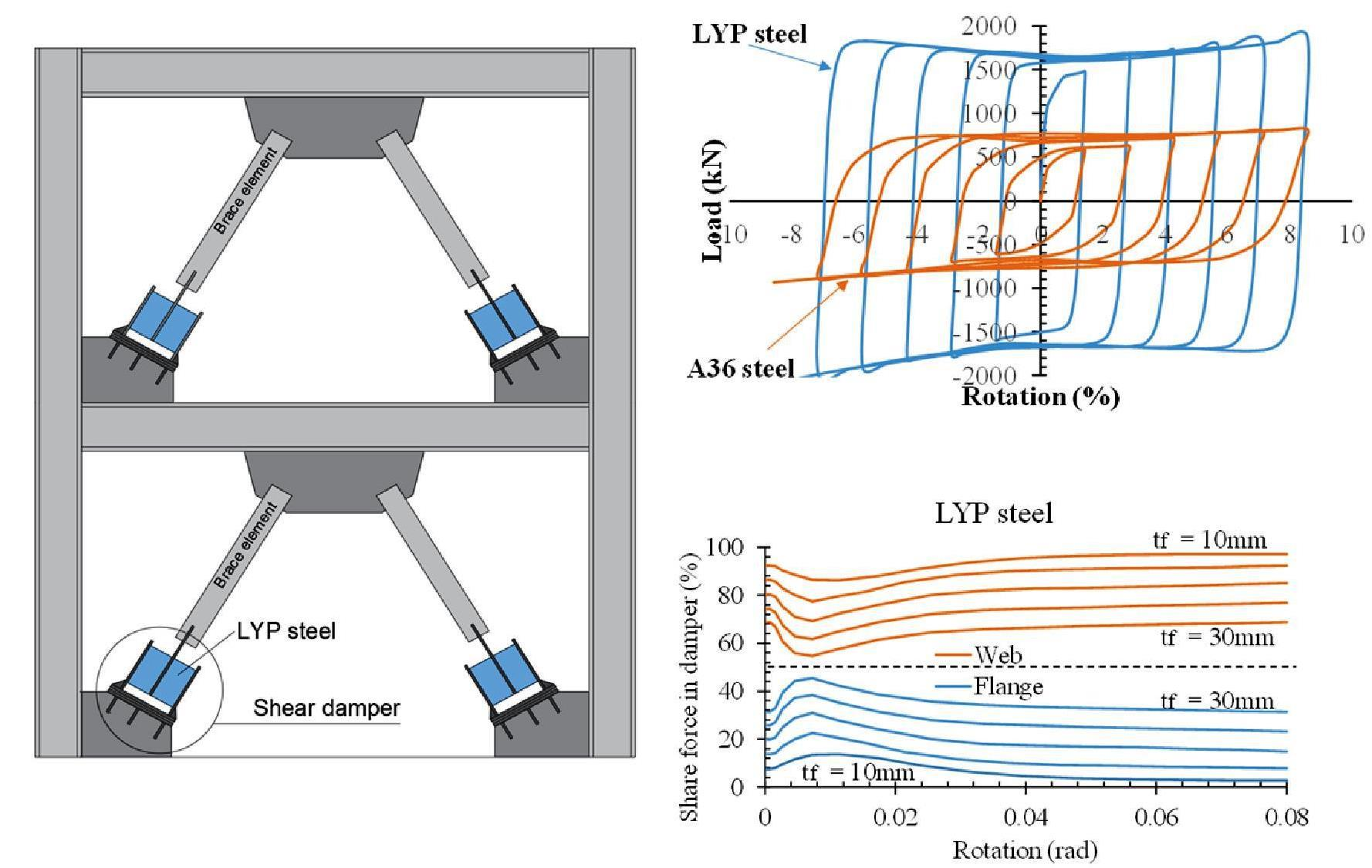
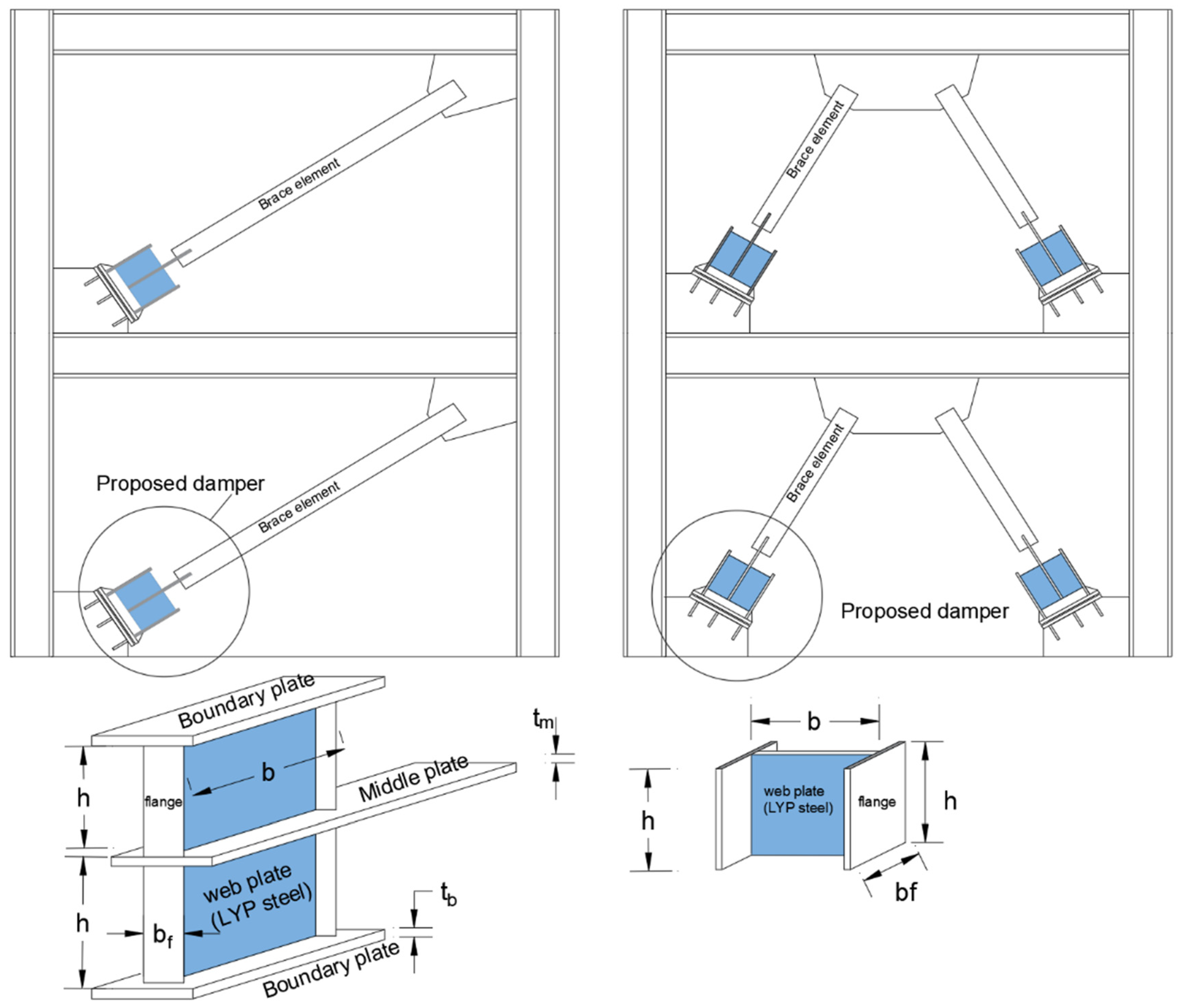
2. The Proposed Shear Link
3. Method of Study
4. Numerical Study
4.1. Modeling
4.2. Verification of the FE results
4.3. Boundary Conditions and Material Properties
5. Parametric Study
6. Results and Discussion
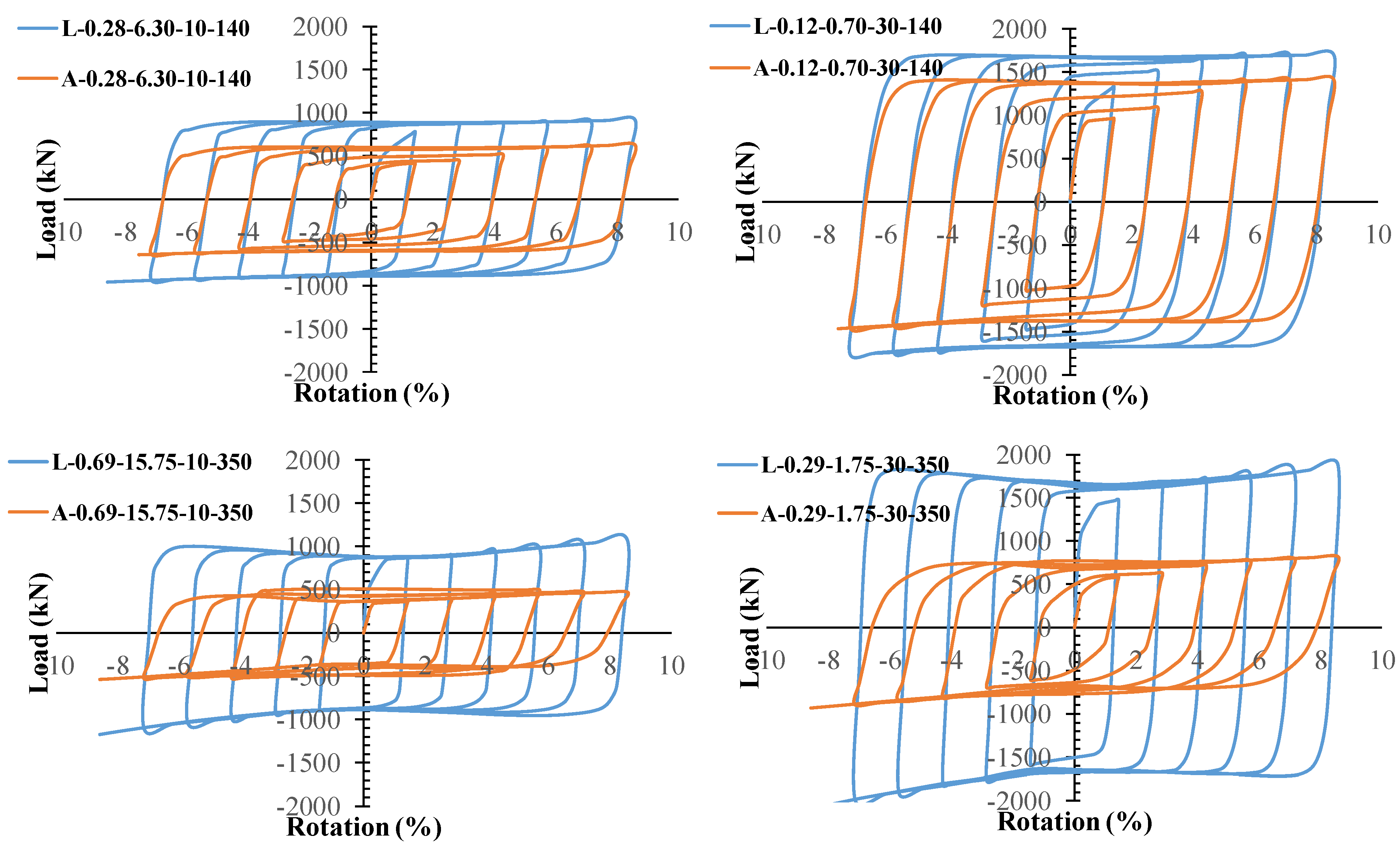
6.1. Hysteresis Curves
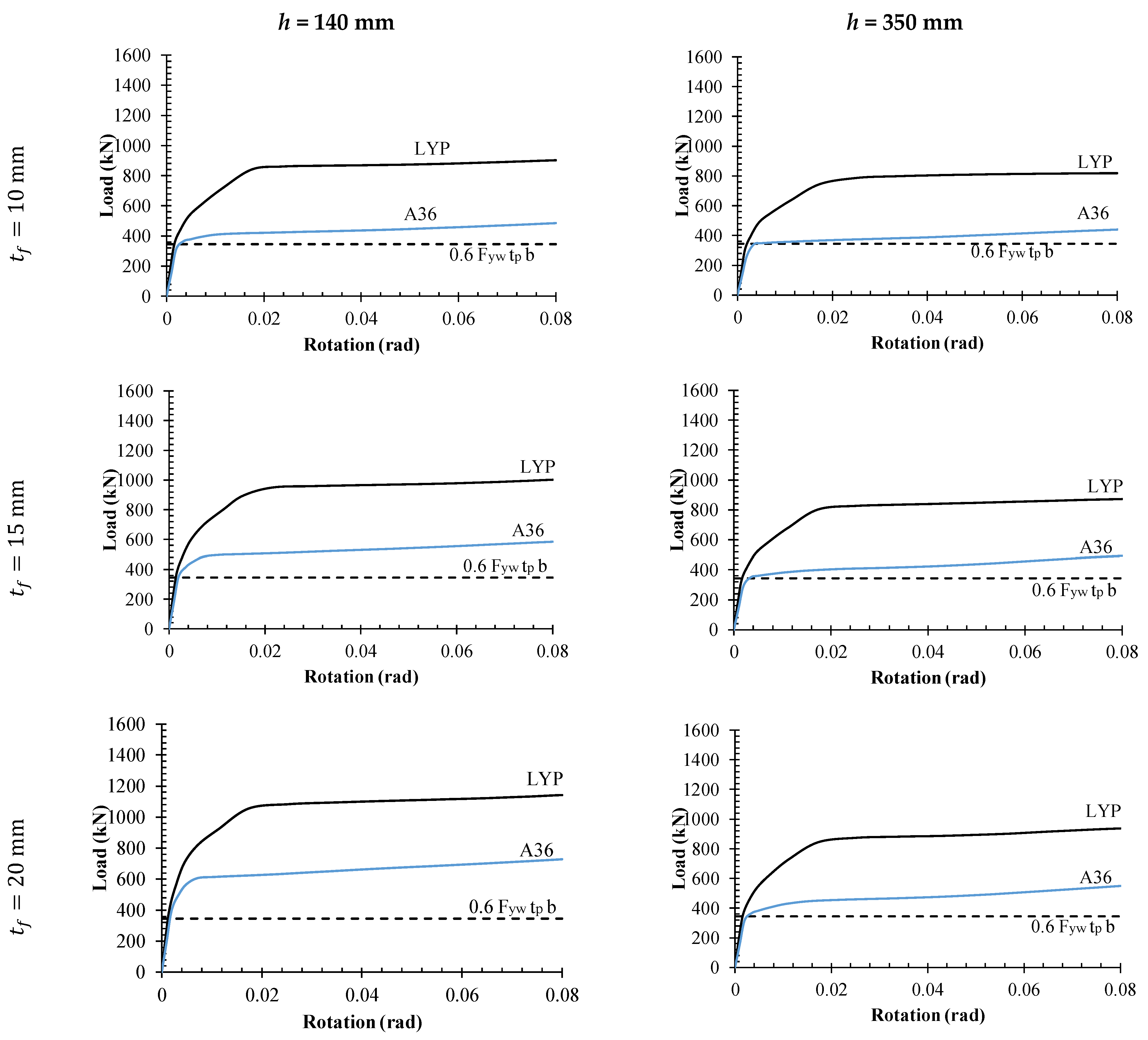
6.2. Load-Rotation Curves
6.3. Comparing the LYP and A36 Dampers
6.4. Influence of ρ on the Stiffness and Strength
6.5. Contribution of the Flange to Shear Strength
6.6. Effect of the Flange on the Damper Response
7. Conclusions
- Both dampers with LYP steel and A36 steel pertain to stable hysteresis loops without any degradation, which confirms the capability of the I-shaped damper to dissipate seismic energy.
- Besides the web plate shear strength as and ρ parameter, some other parameters affect the response of the I-shaped dampers. The Vn was determined based on the AISC 341-16 and, although it measured the minimum shear strength of the I-shaped damper, it should be revised to predict the ultimate strength of the I-shaped damper. In the same situation of , ρ, and ψ, the LYP dampers have a greater dissipating energy and ultimate strength.
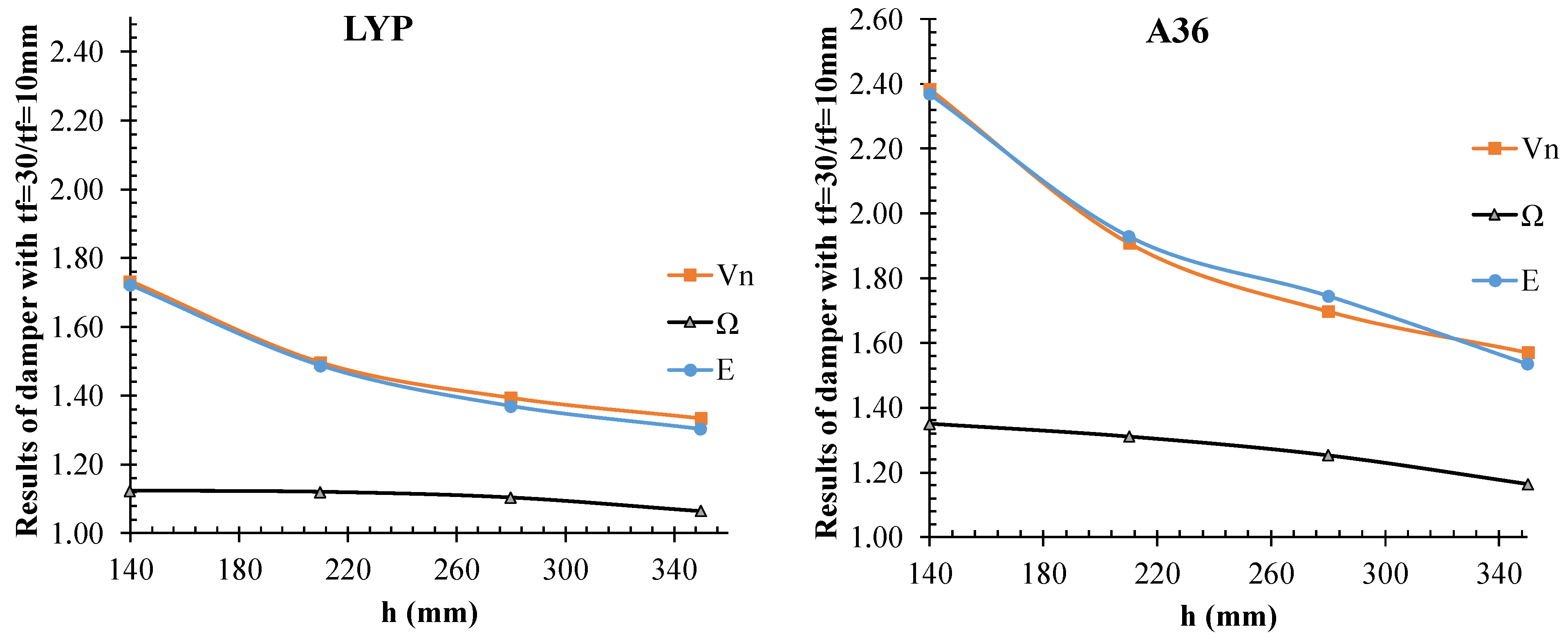
- Results reveal that while tf is increased, the Vn, K, Ω, and E are improved, however this improvement is related to the h reduction as well. Moreover, the A36 damper is more affected by the flange plate stiffness than the LYP damper.
- It is concluded that, for the LYP damper, the flange plate contribution in the shear strength of the damper is ignorable at the beginning of imposed loading. Additionally, for a thin flange plate, the effect of the flange plate on the shear strength can be ignored, which may give low errors of less than 8%. However, the effect of the flange plate on the response of the A36 damper is not ignorable.
- Increasing the parameters of the damper is related to the stiffness of the flange plate. For the LYP damper, the maximum improvement of the parameters Vn, K, Ω, and E for h = 140 mm and h = 350 mm are, respectively, 73% and 33%, 50% and 41%, 12% and 6%, and 72% and 30%. For A36, this is 2.38 times and 57%, 77% and 41%, 35% and 16%, and 2.38 times and 54%.
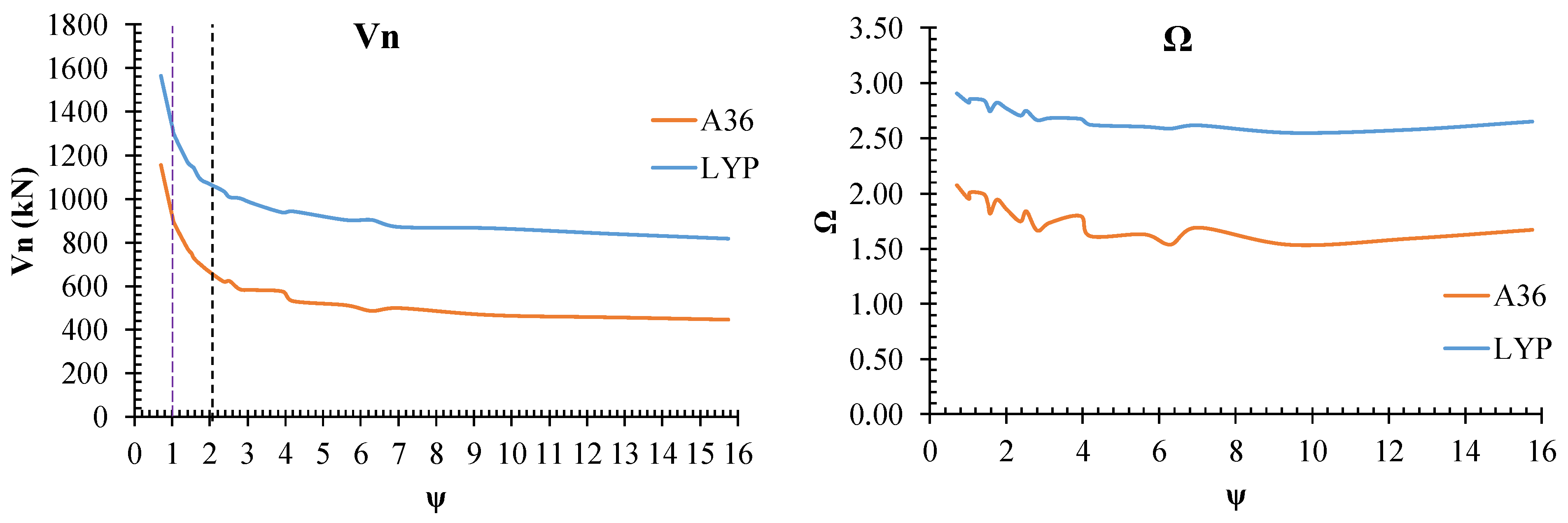
- Since by ψ < 1, the Vn is dropped and through the 1 < ψ < 2 and ψ > 2, respectively, the rate of reduction is reduced and the effect of the flange plate on the Vn is ignorable, the design of a damper with ψ > 2 is suggested to reduce the sensitivity of the Vn to the flange plate properties.
- The minim value of Ω is obtained around ψ = 10. Since the element outside the damper must be designed for ΩVn, a lower Ω helps to reduce the construction cost.
- Recommendations for future work: It is suggested that a comprehensive study be conducted regarding the damper when it is made of A36 steel or LYP steel (for web or all components of the damper) from the economic aspect and to examine the construction costs. In this case, various parameters, including the number of stories, as well as the optimal mode of using this damper, can be obtained.
Author Contributions
Funding
Institutional Review Board Statement
Informed Consent Statement
Data Availability Statement
Acknowledgments
Conflicts of Interest
Abbreviations
| b | web Length of I-shaped link | plastic moment of the flange plate | |
| d | depth of I-shaped link | ratios of the expected yield stress to the specified minimum yield stress for the web | |
| e | link length | ratios of the expected yield stress to the specified minimum yield stress for the flange | |
| E | modulus of elasticity | flange plate thickness | |
| h | height of link | web plate thickness | |
| K | the coefficient for the effective length | design force | |
| length | Vs | loads corresponding to the start of the nonlinear zone | |
| radius of gyration | shear strength of the flange plate | ||
| V | lateral shear applied to the structure | VP | plastic shear capacity |
| Aw | web area section | Vu | ultimate strength |
| flange width | Φ | the compressive strength reduction coefficient | |
| yield stress of the brace | over strength | ||
| web yield stress | ρ | link length ratio | |
| yield stress of the flange plates | shear resistance coefficient | ||
| nominal shear strength | the angle of the diagonal brace element relative to the horizontal | ||
| MP | plastic moment capacity |
References
- Yang, T.Y.; Neitsch, J.; Al-Janabi, M.A.Q.; Tung, D.P. Seismic performance of eccentrically braced frames designed by the conventional and equivalent energy procedures. Soil Dyn. Earthq. Eng. 2020, 139, 106322. [Google Scholar] [CrossRef]
- Ghaedi, K.; Ibrahim, Z.; Javanmardi, A.; Rupakhety, R. Experimental study of a new bar damper device for vibration control of structures subjected to earthquake loads. J. Earthq. Eng. 2018, 25, 300–318. [Google Scholar] [CrossRef]
- Engelhardt, M.D.; Popov, E.P. Experimental performance of long links in eccentrically braced frames. J. Struct. Eng. 1992, 118, 3067–3088. [Google Scholar] [CrossRef]
- Nuzzo, I.; Losanno, D.; Serino, G.; Bozzo, L. A seismic resistant precast RC system equipped with shear link dissipators for residential buildings. In Proceedings of the Second International Conference on Advances in Civil, Structural and Environmental Engineering, Zurich, Switzerland, 25–26 October 2014; Volume 2, pp. 249–254. [Google Scholar] [CrossRef]
- Mohsenian, V.; Hajirasouliha, I.; Filizadeh, R. Seismic reliability analysis of steel moment-resisting frames retrofitted by vertical link elements using combined series–parallel system approach. Bull. Earthq. Eng. 2021, 19, 831–862. [Google Scholar] [CrossRef]
- Corte, D.; D’Aniello, M.; Landolfo, R. Analytical and numerical study of plastic overstrength of shear links. J. Constr. Steel Res. 2013, 82, 19–32. [Google Scholar] [CrossRef]
- Ji, X.; Wang, Y.; Ma, Q.; Okazaki, T. Cyclic behavior of very short steel shear links. J. Struct. Eng. 2016, 142, 04015114. [Google Scholar] [CrossRef]
- Bozkurt, M.; Topkaya, C. Replaceable links with gusseted brace joints for eccentrically braced frames. Soil Dyn. Earthq. Eng. 2018, 115, 305–318. [Google Scholar] [CrossRef]
- Chesoan, A.; Stratan, A.; Dubina, D. Design implementation of re-centring dual eccentrically braced frames with removable links. Soil Dyn. Earthq. Eng. 2018, 112, 174–184. [Google Scholar] [CrossRef]
- Zahrai, S.M.; Parsa, A. Effect of flange width of vertical link beam on cyclic behavior of chevron braced steel frames. J. Seismol. Earthq. Eng. 2015, 17, 281–292. [Google Scholar]
- Valente, M.; Milani, G. Alternative retrofitting strategies to prevent the failure of an underdesigned reinforced concrete frame. Eng. Fail. Anal. 2018, 89, 271–285. [Google Scholar] [CrossRef]
- Mazzolani, F.M.; Corte, G.D.; D’Aniello, M. Experimental analysis of steel dissipative bracing systems for seismic upgrading. J. Civ. Eng. Manag. 2009, 15, 7–19. [Google Scholar] [CrossRef]
- Najari Varzaneh, M.; Hosseini, M.; Akbarpoor, A. The Study of EADAS Elliptical Steel Damper Function in Seismic Resisting of Steel Frames. J. Rehabil. Civ. Eng. 2014, 2, 40–45. [Google Scholar]
- Shih, M.-H.; Sung, W.-P.; Go, C.-G. Investigation of newly developed added damping and stiffness device with low yield strength steel. J. Zhejiang Univ. Sci. 2004, 5, 326–334. [Google Scholar] [CrossRef] [PubMed]
- Shojaeifara, H.; Maleki, A.; Lotfollahi-Yaghin, A. Performance Evaluation of Curved-TADAS Damper on Seismic Response of Moment Resisting Steel Frame. Int. J. Eng. 2020, 33, 55–67. [Google Scholar]
- Özkaynak, H. Model Proposal for Steel Cushions for Use in Reinforced Concrete Frames. KSCE J. Civ. Eng. 2017, 21, 2717–2727. [Google Scholar] [CrossRef]
- Miao, F.; Nejati, F.; Zubair, S.A.M.; Yassin, M.E. Seismic Performance of Eccentrical Braced Frame Retrofitted by Box Damper in Vertical Links. Buildings 2022, 12, 1506. [Google Scholar] [CrossRef]
- Helm, L.; Sadegh-Azar, H.; Jahnel, L.; Jandrey, H. Application and Optimization of Ring Spring Dampers for Seismic Design. In Proceedings of the 10th International Conference on Behaviour of Steel Structures in Seismic Areas, Timisoara, Romania, 25–27 May 2022; STESSA 2022; Lecture Notes in Civil Engineering. Mazzolani, F.M., Dubina, D., Stratan, A., Eds.; Springer International Publishing: Cham, Switzerland, 2022. Note No. 262. [Google Scholar] [CrossRef]
- Sahoo, D.R.; Singhal, T.; Taraithia, S.; Saini, A. Cyclic behavior of shear-and-flexural yielding metallic dampers. J. Constr. Steel Res. 2015, 114, 247–257. [Google Scholar] [CrossRef]
- Ghamari, A.; Kim, C.-H.; Jeong, S.-H.; Hong, K.-J. Development of an innovative metallic damper for concentrically braced frame systems based on experimental and analytical studies. Struct. Des. Tall Spec. Build. 2022, 31, e1927. [Google Scholar] [CrossRef]
- Ghamari, A.; Almasi, B.; Kim, C.-H.; Jeong, S.-H.; Hong, K.-J. An Innovative Steel Damper with a Flexural and Shear–Flexural Mechanism to Enhance the CBF System Behavior: An Experimental and Numerical Study. Appl. Sci. 2021, 11, 11454. [Google Scholar] [CrossRef]
- Thongchom, C.; Bahrami, A.; Ghamari, A.; Benjeddou, O. Performance Improvement of Innovative Shear Damper Using Diagonal Stiffeners for Concentrically Braced Frame Systems. Buildings 2022, 12, 1794. [Google Scholar] [CrossRef]
- Thongchom, C.; Ghamari, A.; Putra Jaya, R.; Benjeddoud, O. Experimental and Numerical Study on an Innovative Trapezoidal-Shaped Damper to Improve the Behavior of CBF Braces. Buildings 2023, 13, 140. [Google Scholar] [CrossRef]
- Giannuzzi, D.; Ballarini, R.; Huckelbridge, A.; Pollino, M.; Valente, M. Braced Ductile Shear Panel: New Seismic-Resistant Framing System. J. Struct. Eng. 2014, 140, 04013050. [Google Scholar] [CrossRef]
- Tanaka, T.; Sasaki, Y. Hysteresis Performance of Shear Panel Dampers of Ultra Low Yield Strength Steel for Seismic Response Control of Building. In Proceedings of the 12th World Conference on Earthquake Engineering, Auckland, New Zealand, 30 January–4 February 2000. [Google Scholar]
- Choi, J.; Abebe, D. Hysteresis Characteristics of Shear Panel Damper Using SLY120. APCBEE Procedia 2014, 9, 370–375. [Google Scholar] [CrossRef]
- Okazaki, T.; Engelhardt, M.D. Cyclic loading behavior of EBF links constructed of ASTM A992 steel. J. Constr. Steel Res. 2007, 63, 751–765. [Google Scholar] [CrossRef]
- AISC. AISC 341-16; Seismic Provisions for Structural Steel Buildings. American Institute of Steel Construction: Chicago, IL, USA, 2016.
- ANSI/AISC 360-16; Specification for Structural Steel Buildings. American Institute of Steel Construction: Chicago, IL, USA, 2016; pp. 1–612.
- Ghadami, A.; Pourmoosavi, G.; Ghamari, A. Seismic design of elements outside of the short low-yield-point steel shear links. J. Constr. Steel Res. 2021, 178, 106489. [Google Scholar] [CrossRef]
- Sabouri-Ghomi, S.; Ziaei, M. A study on the behavior of shear link beam made of easy-going steel in eccentrically braced frames. In Proceedings of the 14th World Conference on Earthquake Engineering, Beijing, China, 12–17 October 2008. [Google Scholar]
- Dusicka, P.; Itani, A.M.; Buckle, I.G. Cyclic behavior of shear links of various grades of plate steel. J. Struct. Eng. 2010, 136, 370–378. [Google Scholar] [CrossRef]
- Kasai, K.; Popov, E.P. A Study of Seismically Resistant Eccentrically Braced 418 Frames; Rep. No. UCB/EERC-86/01; Earthquake Engineering Research Center, University of California: Berkeley, CA, USA, 1983. [Google Scholar]
- Hjelmstad, K.D.; Popov, E.P. Seismic Behavior of Active Beam Link in Eccentrically Braced Frames; Rep. No. UCB/EERC-83/15; Earthquake Engineering Research Center, University of California: Berkeley, CA, USA, 1983. [Google Scholar]
- Engelhardt, M.D.; Popov, E.P. Behavior of Long Links in Eccentrically Braced Frames; Rep. No. UCB/EERC-89/01; Earthquake Engineering Research Center, University of California: Berkeley, CA, USA, 1989. [Google Scholar]
- Okazaki, T.; Engelhardt, M.D.; Drolias, A.; Schell, E.; Hong, J.K.; Uang, C.M. Experimental investigation of link-to-column connections in eccentrically braced frames. J. Constr. Steel Res. 2009, 65, 1401–1412. [Google Scholar] [CrossRef]
- McDaniel, C.C.; Uang, C.M.; Seible, F. Cyclic testing of built-up steel shear links for the new bay bridge. J. Struct. Eng. 2003, 129, 801–809. [Google Scholar] [CrossRef]
- Manheim, D.N.; Popov, E.P. Plastic shear hinges in steel frames. J. Struct. Eng. 1983, 10, 2404–2419. [Google Scholar] [CrossRef]
- Richards, P.W. Cyclic Stability and Capacity Design of Steel Eccentrically Braced Frames. Ph.D. Thesis, Department of Structural Engineering, University of California, San Diego, CA, USA, 2004. [Google Scholar]
- Applied Technology Council (ATC). Guildlines for Cyclic Seismic Testing of Component for Steel Structures; ATC-24 Report; Applied Technology Council (ATC): Redwood City, CA, USA, 1992. [Google Scholar]


| Materials | Fy (MPa) | Fu (MPa) | Modulus of Elasticity (GPa) |
|---|---|---|---|
| LYP100 | 100 | 257 | 153 |
| A36 | 235 | 360 | 200 |
| FE Model (ρ-ψ-tf-h) | h (mm) | tp (mm) | tf (mm) | ρ | ψ | Web Plate Material |
|---|---|---|---|---|---|---|
| L-0.21-6.3-10-140 | 140 | 14 | 10 | 0.21 | 6.30 | LYP |
| L-0.15-2.8-15-140 | 140 | 14 | 15 | 0.15 | 2.80 | LYP |
| L-0.12-1.58-20-140 | 140 | 14 | 20 | 0.12 | 1.58 | LYP |
| L-0.10-1.00-25-140 | 140 | 14 | 25 | 0.10 | 1.01 | LYP |
| L-0.08-0.7-30-140 | 140 | 14 | 30 | 0.08 | 0.70 | LYP |
| L-0.32-9.45-10-210 | 210 | 14 | 10 | 0.32 | 9.45 | LYP |
| L-0.23-4.2-15-210 | 210 | 14 | 15 | 0.23 | 4.20 | LYP |
| L-0.18-2.36-20-210 | 210 | 14 | 20 | 0.18 | 2.36 | LYP |
| L-0.15-1.51-25-210 | 210 | 14 | 25 | 0.15 | 1.51 | LYP |
| L-0.12-1.05-30-210 | 210 | 14 | 30 | 0.12 | 1.05 | LYP |
| L-0.42-12.6-10-280 | 280 | 14 | 10 | 0.42 | 12.60 | LYP |
| L-0.31-5.6-15-280 | 280 | 14 | 15 | 0.31 | 5.60 | LYP |
| L-0.24-3.15-20-280 | 280 | 14 | 20 | 0.24 | 3.15 | LYP |
| L-0.19-2.02-25-280 | 280 | 14 | 25 | 0.19 | 2.02 | LYP |
| L-0.16-1.4-30-280 | 280 | 14 | 30 | 0.16 | 1.40 | LYP |
| L-0.53-15.75-10-350 | 350 | 14 | 10 | 0.53 | 15.75 | LYP |
| L-0.38-7.0-15-350 | 350 | 14 | 15 | 0.38 | 7.00 | LYP |
| L-0.30-3.94-20-350 | 350 | 14 | 20 | 0.30 | 3.94 | LYP |
| L-0.24-2.52-25-350 | 350 | 14 | 25 | 0.24 | 2.52 | LYP |
| L-0.20-1.75-30-350 | 350 | 14 | 30 | 0.20 | 1.75 | LYP |
| 140-10-0.25-6.3 | 140 | 6 | 10 | 0.25 | 6.30 | A36 |
| 140-15-0.18-2.8 | 140 | 6 | 15 | 0.18 | 2.80 | A36 |
| 140-20-0.13-1.58 | 140 | 6 | 20 | 0.13 | 1.58 | A36 |
| 140-25-0.11-1.00 | 140 | 6 | 25 | 0.11 | 1.01 | A36 |
| 140-30-0.10-0.7 | 140 | 6 | 30 | 0.09 | 0.70 | A36 |
| 210-10-0.38-9.45 | 210 | 6 | 10 | 0.38 | 9.45 | A36 |
| 210-115-0.26-4.2 | 210 | 6 | 15 | 0.26 | 4.20 | A36 |
| 210-20-0.2-2.36 | 210 | 6 | 20 | 0.20 | 2.36 | A36 |
| 210-250-0.16-1.51 | 210 | 6 | 25 | 0.16 | 1.51 | A36 |
| 210-30-0.13-1.05 | 210 | 6 | 30 | 0.13 | 1.05 | A36 |
| 280-10-0.51-12.6 | 280 | 6 | 10 | 0.51 | 12.60 | A36 |
| 280-15-0.35-5.6 | 280 | 6 | 15 | 0.35 | 5.60 | A36 |
| 280-20-0.26-3.15 | 280 | 6 | 20 | 0.26 | 3.15 | A36 |
| 280-25-0.21-2.02 | 280 | 6 | 25 | 0.21 | 2.02 | A36 |
| 280-30-0.17-1.4 | 280 | 6 | 30 | 0.17 | 1.40 | A36 |
| 350-10-0.64-15.75 | 350 | 6 | 10 | 0.64 | 15.75 | A36 |
| 350-15-0.44-7.0 | 350 | 6 | 15 | 0.44 | 7.00 | A36 |
| 350-20-0.33-3.94 | 350 | 6 | 20 | 0.33 | 3.94 | A36 |
| 350-25-0.26-2.52 | 350 | 6 | 25 | 0.26 | 2.52 | A36 |
| 350-30-0.22-1.75 | 350 | 6 | 30 | 0.22 | 1.75 | A36 |
| Model | ρ | ψ * | Ultimate Strength | Stiffness (kN/mm) | Δy ** (mm) | Over Strength | Energy Absorption (kN/mm) |
|---|---|---|---|---|---|---|---|
| L-0.28-6.30-10-140 | 0.28 | 6.30 | 903.00 | 1735.68 | 0.52 | 2.59 | 9154.45 |
| L-0.20-2.80-15-140 | 0.20 | 2.80 | 1002.57 | 1885.95 | 0.53 | 2.67 | 10170.36 |
| L-0.16-1.58-20-140 | 0.16 | 1.58 | 1141.08 | 2075.28 | 0.55 | 2.75 | 11592.49 |
| L-0.13-1.01-25-140 | 0.13 | 1.01 | 1327.43 | 2315.11 | 0.57 | 2.83 | 13450.03 |
| L-0.12-0.70-30-140 | 0.12 | 0.70 | 1565.01 | 2603.60 | 0.60 | 2.91 | 15757.71 |
| L-0.42-9.45-10-210 | 0.42 | 9.45 | 864.87 | 1119.50 | 0.77 | 2.55 | 13199.68 |
| L-0.30-4.20-15-210 | 0.30 | 4.20 | 943.12 | 1216.37 | 0.78 | 2.62 | 14192.51 |
| L-0.24-2.36-20-210 | 0.24 | 2.36 | 1035.67 | 1315.03 | 0.79 | 2.71 | 15603.40 |
| L-0.20-1.51-25-210 | 0.20 | 1.51 | 1151.15 | 1425.64 | 0.81 | 2.79 | 17415.94 |
| L-0.17-1.05-30-210 | 0.17 | 1.05 | 1294.67 | 1554.17 | 0.83 | 2.86 | 19630.52 |
| L-0.55-12.60-10-280 | 0.55 | 12.60 | 840.17 | 780.42 | 1.08 | 2.58 | 17146.26 |
| L-0.40-5.60-15-280 | 0.40 | 5.60 | 903.26 | 858.92 | 1.05 | 2.61 | 18164.80 |
| L-0.32-3.15-20-280 | 0.32 | 3.15 | 978.73 | 929.33 | 1.05 | 2.69 | 19510.22 |
| L-0.27-2.02-25-280 | 0.27 | 2.02 | 1066.74 | 1000.04 | 1.07 | 2.77 | 21288.09 |
| L-0.23-1.40-30-280 | 0.23 | 1.40 | 1171.13 | 1075.75 | 1.09 | 2.85 | 23483.36 |
| L-0.69-15.75-10-350 | 0.69 | 15.75 | 817.28 | 567.65 | 1.44 | 2.65 | 20879.16 |
| L-0.50-7.00-15-350 | 0.50 | 7.00 | 871.22 | 635.23 | 1.37 | 2.62 | 22043.02 |
| L-0.40-3.94-20-350 | 0.40 | 3.94 | 936.96 | 692.19 | 1.35 | 2.68 | 23390.80 |
| L-0.33-2.52-25-350 | 0.33 | 2.52 | 1008.55 | 745.70 | 1.35 | 2.75 | 25070.53 |
| L-0.29-1.75-30-350 | 0.29 | 1.75 | 1090.51 | 799.23 | 1.36 | 2.83 | 27192.85 |
| A-0.28-6.30-10-140 | 0.28 | 6.30 | 484.76 | 1126.24 | 0.43 | 1.54 | 4818.12 |
| A-0.20-2.80-15-140 | 0.20 | 2.80 | 583.88 | 1254.71 | 0.47 | 1.67 | 5814.61 |
| A-0.16-1.58-20-140 | 0.16 | 1.58 | 727.55 | 1437.60 | 0.51 | 1.82 | 7239.76 |
| A-0.13-1.01-25-140 | 0.13 | 1.01 | 917.02 | 1684.32 | 0.54 | 1.95 | 9103.13 |
| A-0.12-0.70-30-140 | 0.12 | 0.70 | 1155.30 | 1989.45 | 0.58 | 2.08 | 11409.81 |
| A-0.42-9.45-10-210 | 0.42 | 9.45 | 465.46 | 722.55 | 0.64 | 1.53 | 6830.08 |
| A-0.30-4.20-15-210 | 0.30 | 4.20 | 530.31 | 789.86 | 0.67 | 1.61 | 7790.79 |
| A-0.24-2.36-20-210 | 0.24 | 2.36 | 620.16 | 868.41 | 0.71 | 1.75 | 9163.62 |
| A-0.20-1.51-25-210 | 0.20 | 1.51 | 749.37 | 966.74 | 0.78 | 1.91 | 11761.62 |
| A-0.17-1.05-30-210 | 0.17 | 1.05 | 888.29 | 1089.47 | 0.82 | 2.01 | 13171.23 |
| A-0.55-12.60-10-280 | 0.55 | 12.60 | 455.72 | 511.26 | 0.89 | 1.59 | 9239.47 |
| A-0.40-5.60-15-280 | 0.40 | 5.60 | 511.02 | 560.45 | 0.91 | 1.63 | 9922.06 |
| A-0.32-3.15-20-280 | 0.32 | 3.15 | 581.32 | 609.31 | 0.95 | 1.74 | 11659.08 |
| A-0.27-2.02-25-280 | 0.27 | 2.02 | 661.21 | 663.91 | 1.00 | 1.85 | 13189.83 |
| A-0.23-1.40-30-280 | 0.23 | 1.40 | 773.43 | 727.96 | 1.06 | 2.00 | 16122.70 |
| A-0.69-15.75-10-350 | 0.69 | 15.75 | 444.70 | 380.43 | 1.17 | 1.67 | 11286.43 |
| A-0.50-7.00-15-350 | 0.50 | 7.00 | 498.51 | 421.27 | 1.18 | 1.69 | 12361.18 |
| A-0.40-3.94-20-350 | 0.40 | 3.94 | 573.63 | 457.88 | 1.25 | 1.80 | 15725.37 |
| A-0.33-2.52-25-350 | 0.33 | 2.52 | 621.87 | 495.27 | 1.26 | 1.84 | 15518.53 |
| A-0.29-1.75-30-350 | 0.29 | 1.75 | 698.29 | 536.03 | 1.30 | 1.95 | 17326.80 |
| ρ | ψ * | tf ** (mm) | LYP Damper Divided by A36 Damper | ||||
|---|---|---|---|---|---|---|---|
| Ultimate Strength | Stiffness | Over Strength | Energy Absorption | ||||
| 0.28 | 6.30 | 10 | 1.86 | 1.54 | 1.68 | 1.90 | |
| 0.20 | 2.80 | 15 | 1.72 | 1.50 | 1.60 | 1.75 | |
| 0.16 | 1.58 | 20 | 1.57 | 1.44 | 1.51 | 1.60 | |
| 0.13 | 1.01 | 25 | 1.45 | 1.37 | 1.45 | 1.48 | |
| 0.12 | 0.70 | 30 | 1.35 | 1.31 | 1.40 | 1.38 | |
| 0.42 | 9.45 | 10 | 1.86 | 1.55 | 1.66 | 1.93 | |
| 0.30 | 4.20 | 15 | 1.78 | 1.54 | 1.63 | 1.82 | |
| 0.24 | 2.36 | 20 | 1.67 | 1.51 | 1.55 | 1.70 | |
| 0.20 | 1.51 | 25 | 1.54 | 1.47 | 1.46 | 1.48 | |
| 0.17 | 1.05 | 30 | 1.46 | 1.43 | 1.42 | 1.49 | |
| 0.55 | 12.60 | 10 | 1.84 | 1.53 | 1.62 | 1.86 | |
| 0.40 | 5.60 | 15 | 1.77 | 1.53 | 1.60 | 1.83 | |
| 0.32 | 3.15 | 20 | 1.68 | 1.53 | 1.55 | 1.67 | |
| 0.27 | 2.02 | 25 | 1.61 | 1.51 | 1.50 | 1.61 | |
| 0.23 | 1.40 | 30 | 1.51 | 1.48 | 1.43 | 1.46 | |
| 0.69 | 15.75 | 10 | 1.84 | 1.49 | 1.59 | 1.85 | |
| 0.50 | 7.00 | 15 | 1.75 | 1.51 | 1.55 | 1.78 | |
| 0.40 | 3.94 | 20 | 1.63 | 1.51 | 1.49 | 1.49 | |
| 0.33 | 2.52 | 25 | 1.62 | 1.51 | 1.50 | 1.62 | |
| 0.29 | 1.75 | 30 | 1.56 | 1.49 | 1.45 | 1.57 | |
| Model | ρ | ψ * | tf ** (mm) | Rotation = 0 | Rotation 8% | ||
|---|---|---|---|---|---|---|---|
| Flange Plate | Web Plate | Flange Plate | Web Plate | ||||
| L-0.28-6.30-10-140 | 0.28 | 6.30 | 10 | 7.62 | 92.38 | 2.93 | 97.07 |
| L-0.20-2.80-15-140 | 0.20 | 2.80 | 15 | 13.72 | 86.28 | 8.29 | 91.71 |
| L-0.16-1.58-20-140 | 0.16 | 1.58 | 20 | 19.83 | 80.17 | 15.43 | 84.57 |
| L-0.13-1.01-25-140 | 0.13 | 1.01 | 25 | 25.76 | 74.24 | 23.66 | 76.34 |
| L-0.12-0.70-30-140 | 0.12 | 0.70 | 30 | 31.29 | 68.71 | 31.67 | 68.33 |
| L-0.42-9.45-10-210 | 0.42 | 9.45 | 10 | 6.62 | 93.38 | 2.10 | 97.90 |
| L-0.30-4.20-15-210 | 0.30 | 4.20 | 15 | 11.95 | 88.05 | 3.09 | 96.91 |
| L-0.24-2.36-20-210 | 0.24 | 2.36 | 20 | 16.80 | 83.20 | 7.32 | 92.68 |
| L-0.20-1.51-25-210 | 0.20 | 1.51 | 25 | 20.93 | 79.07 | 12.35 | 87.65 |
| L-0.17-1.05-30-210 | 0.17 | 1.05 | 30 | 24.43 | 75.57 | 17.99 | 82.01 |
| L-0.55-12.60-10-280 | 0.55 | 12.60 | 10 | 5.98 | 94.02 | 3.69 | 96.31 |
| L-0.40-5.60-15-280 | 0.40 | 5.60 | 15 | 11.09 | 88.91 | 1.92 | 98.08 |
| L-0.32-3.15-20-280 | 0.32 | 3.15 | 20 | 15.83 | 84.17 | 3.65 | 96.35 |
| L-0.27-2.02-25-280 | 0.27 | 2.02 | 25 | 19.72 | 80.28 | 6.03 | 93.97 |
| L-0.23-1.40-30-280 | 0.23 | 1.40 | 30 | 22.71 | 77.29 | 10.95 | 89.05 |
| L-0.69-15.75-10-350 | 0.69 | 15.75 | 10 | 5.42 | 94.58 | 6.64 | 93.36 |
| L-0.50-7.00-15-350 | 0.50 | 7.00 | 15 | 10.31 | 89.69 | 2.46 | 97.54 |
| L-0.40-3.94-20-350 | 0.40 | 3.94 | 20 | 14.97 | 85.03 | 1.74 | 98.26 |
| L-0.33-2.52-25-350 | 0.33 | 2.52 | 25 | 18.86 | 81.14 | 2.94 | 97.06 |
| L-0.29-1.75-30-350 | 0.29 | 1.75 | 30 | 21.86 | 78.14 | 6.45 | 93.55 |
| A-0.28-6.30-10-140 | 0.28 | 6.30 | 10 | 11.07 | 88.93 | 9.38 | 90.62 |
| A-0.20-2.80-15-140 | 0.20 | 2.80 | 15 | 23.39 | 76.61 | 24.48 | 75.52 |
| A-0.16-1.58-20-140 | 0.16 | 1.58 | 20 | 27.34 | 72.66 | 29.56 | 70.44 |
| A-0.13-1.01-25-140 | 0.13 | 1.01 | 25 | 34.95 | 65.05 | 39.11 | 60.89 |
| A-0.12-0.70-30-140 | 0.12 | 0.70 | 30 | 41.60 | 58.40 | 47.04 | 52.96 |
| A-0.42-9.45-10-210 | 0.42 | 9.45 | 10 | 9.79 | 90.21 | 7.58 | 92.42 |
| A-0.30-4.20-15-210 | 0.30 | 4.20 | 15 | 16.87 | 83.13 | 11.25 | 88.75 |
| A-0.24-2.36-20-210 | 0.24 | 2.36 | 20 | 23.00 | 77.00 | 18.11 | 81.89 |
| A-0.20-1.51-25-210 | 0.20 | 1.51 | 25 | 28.19 | 71.81 | 25.32 | 74.68 |
| A-0.17-1.05-30-210 | 0.17 | 1.05 | 30 | 32.71 | 67.29 | 32.16 | 67.84 |
| A-0.55-12.60-10-280 | 0.55 | 12.60 | 10 | 9.02 | 90.98 | 8.77 | 91.23 |
| A-0.40-5.60-15-280 | 0.40 | 5.60 | 15 | 15.94 | 84.06 | 8.88 | 91.12 |
| A-0.32-3.15-20-280 | 0.32 | 3.15 | 20 | 21.85 | 78.15 | 11.99 | 88.01 |
| A-0.27-2.02-25-280 | 0.27 | 2.02 | 25 | 26.43 | 73.57 | 16.94 | 83.06 |
| A-0.23-1.40-30-280 | 0.23 | 1.40 | 30 | 29.94 | 70.06 | 22.35 | 77.65 |
| A-0.69-15.75-10-350 | 0.69 | 15.75 | 10 | 8.35 | 91.65 | 9.98 | 90.02 |
| A-0.50-7.00-15-350 | 0.50 | 7.00 | 15 | 15.10 | 84.90 | 8.61 | 91.39 |
| A-0.40-3.94-20-350 | 0.40 | 3.94 | 20 | 21.00 | 79.00 | 8.81 | 91.19 |
| A-0.33-2.52-25-350 | 0.33 | 2.52 | 25 | 25.58 | 74.42 | 11.23 | 88.77 |
| A-0.29-1.75-30-350 | 0.29 | 1.75 | 30 | 28.90 | 71.10 | 15.01 | 84.99 |
| Model | ρ | ψ * | tf ** (mm) | ||||
|---|---|---|---|---|---|---|---|
| Ultimate Strength | Stiffness | Over Strength | Energy Absorption | ||||
| L-0.28-6.30-10-140 | 0.28 | 6.30 | 10 | ||||
| L-0.20-2.80-15-140 | 0.20 | 2.80 | 15 | 1.11 | 1.09 | 1.03 | 1.11 |
| L-0.16-1.58-20-140 | 0.16 | 1.58 | 20 | 1.26 | 1.20 | 1.06 | 1.27 |
| L-0.13-1.01-25-140 | 0.13 | 1.01 | 25 | 1.47 | 1.33 | 1.09 | 1.47 |
| L-0.12-0.70-30-140 | 0.12 | 0.70 | 30 | 1.73 | 1.50 | 1.12 | 1.72 |
| L-0.42-9.45-10-210 | 0.42 | 9.45 | 10 | ||||
| L-0.30-4.20-15-210 | 0.30 | 4.20 | 15 | 1.09 | 1.09 | 1.03 | 1.08 |
| L-0.24-2.36-20-210 | 0.24 | 2.36 | 20 | 1.20 | 1.17 | 1.06 | 1.18 |
| L-0.20-1.51-25-210 | 0.20 | 1.51 | 25 | 1.33 | 1.27 | 1.09 | 1.32 |
| L-0.17-1.05-30-210 | 0.17 | 1.05 | 30 | 1.50 | 1.39 | 1.12 | 1.49 |
| L-0.55-12.60-10-280 | 0.55 | 12.60 | 10 | ||||
| L-0.40-5.60-15-280 | 0.40 | 5.60 | 15 | 1.08 | 1.10 | 1.01 | 1.06 |
| L-0.32-3.15-20-280 | 0.32 | 3.15 | 20 | 1.16 | 1.19 | 1.04 | 1.14 |
| L-0.27-2.02-25-280 | 0.27 | 2.02 | 25 | 1.27 | 1.28 | 1.07 | 1.24 |
| L-0.23-1.40-30-280 | 0.23 | 1.40 | 30 | 1.39 | 1.38 | 1.10 | 1.37 |
| L-0.69-15.75-10-350 | 0.69 | 15.75 | 10 | ||||
| L-0.50-7.00-15-350 | 0.50 | 7.00 | 15 | 1.07 | 1.12 | 0.99 | 1.06 |
| L-0.40-3.94-20-350 | 0.40 | 3.94 | 20 | 1.15 | 1.22 | 1.01 | 1.12 |
| L-0.33-2.52-25-350 | 0.33 | 2.52 | 25 | 1.23 | 1.31 | 1.04 | 1.20 |
| L-0.29-1.75-30-350 | 0.29 | 1.75 | 30 | 1.33 | 1.41 | 1.06 | 1.30 |
| A-0.28-6.30-10-140 | 0.28 | 6.30 | 10 | ||||
| A-0.20-2.80-15-140 | 0.20 | 2.80 | 15 | 1.20 | 1.11 | 1.08 | 1.21 |
| A-0.16-1.58-20-140 | 0.16 | 1.58 | 20 | 1.50 | 1.28 | 1.18 | 1.50 |
| A-0.13-1.01-25-140 | 0.13 | 1.01 | 25 | 1.89 | 1.50 | 1.27 | 1.89 |
| A-0.12-0.70-30-140 | 0.12 | 0.70 | 30 | 2.38 | 1.77 | 1.35 | 2.37 |
| A-0.42-9.45-10-210 | 0.42 | 9.45 | 10 | ||||
| A-0.30-4.20-15-210 | 0.30 | 4.20 | 15 | 1.14 | 1.09 | 1.05 | 1.14 |
| A-0.24-2.36-20-210 | 0.24 | 2.36 | 20 | 1.33 | 1.20 | 1.14 | 1.34 |
| A-0.20-1.51-25-210 | 0.20 | 1.51 | 25 | 1.61 | 1.34 | 1.25 | 1.72 |
| A-0.17-1.05-30-210 | 0.17 | 1.05 | 30 | 1.91 | 1.51 | 1.31 | 1.93 |
| A-0.55-12.60-10-280 | 0.55 | 12.60 | 10 | ||||
| A-0.40-5.60-15-280 | 0.40 | 5.60 | 15 | 1.12 | 1.10 | 1.02 | 1.07 |
| A-0.32-3.15-20-280 | 0.32 | 3.15 | 20 | 1.28 | 1.19 | 1.09 | 1.26 |
| A-0.27-2.02-25-280 | 0.27 | 2.02 | 25 | 1.45 | 1.30 | 1.16 | 1.43 |
| A-0.23-1.40-30-280 | 0.23 | 1.40 | 30 | 1.70 | 1.42 | 1.25 | 1.74 |
| A-0.69-15.75-10-350 | 0.69 | 15.75 | 10 | ||||
| A-0.50-7.00-15-350 | 0.50 | 7.00 | 15 | 1.12 | 1.11 | 1.01 | 1.10 |
| A-0.40-3.94-20-350 | 0.40 | 3.94 | 20 | 1.29 | 1.20 | 1.07 | 1.39 |
| A-0.33-2.52-25-350 | 0.33 | 2.52 | 25 | 1.40 | 1.30 | 1.10 | 1.37 |
| A-0.29-1.75-30-350 | 0.29 | 1.75 | 30 | 1.57 | 1.41 | 1.16 | 1.54 |
Disclaimer/Publisher’s Note: The statements, opinions and data contained in all publications are solely those of the individual author(s) and contributor(s) and not of MDPI and/or the editor(s). MDPI and/or the editor(s) disclaim responsibility for any injury to people or property resulting from any ideas, methods, instructions or products referred to in the content. |
© 2023 by the authors. Licensee MDPI, Basel, Switzerland. This article is an open access article distributed under the terms and conditions of the Creative Commons Attribution (CC BY) license (https://creativecommons.org/licenses/by/4.0/).
Share and Cite
Ghamari, A.; Thongchom, C.; Putra Jaya, R.; Sithole, T. Utilizing Low Yield Point Steel to Improve the Behavior of the I-Shaped Shear Links as Dampers. Buildings 2023, 13, 554. https://doi.org/10.3390/buildings13020554
Ghamari A, Thongchom C, Putra Jaya R, Sithole T. Utilizing Low Yield Point Steel to Improve the Behavior of the I-Shaped Shear Links as Dampers. Buildings. 2023; 13(2):554. https://doi.org/10.3390/buildings13020554
Chicago/Turabian StyleGhamari, Ali, Chanachai Thongchom, Ramadhansyah Putra Jaya, and Thandiwe Sithole. 2023. "Utilizing Low Yield Point Steel to Improve the Behavior of the I-Shaped Shear Links as Dampers" Buildings 13, no. 2: 554. https://doi.org/10.3390/buildings13020554
APA StyleGhamari, A., Thongchom, C., Putra Jaya, R., & Sithole, T. (2023). Utilizing Low Yield Point Steel to Improve the Behavior of the I-Shaped Shear Links as Dampers. Buildings, 13(2), 554. https://doi.org/10.3390/buildings13020554