Abstract
Point cloud data have become the primary spatial data source for the 3D reconstruction of building engineering, where 3D reconstructed building information models can improve construction efficiency. In such applications, detecting windows and doors is essential. Previous research mainly used red-green-blue (RGB) information or semantic features for detection, where the combination of these two features was not considered. Therefore, this research proposed a practical approach to detecting windows and doors using point cloud data with the combination of semantic features and material characteristics. The point cloud data are first segmented using Gradient Filtering and Random Sample Consensus (RANSAC) to obtain the 3D indoor data without intrusions and protrusions. As input, the 3D indoor data are projected to horizontal planes as 2D point cloud data. The 2D point cloud data are then transformed to 2D images, representing the indoor area for feature extraction. On the 2D images, the 2D boundary of each potential opening is extracted using an improved Bounding Box algorithm, and the extraction result is transformed back to 3D data. Based on the 3D data, the reflectivity of building material is applied to differentiate windows and doors from potential openings, and the number of data points is used to check the opening condition of windows and doors. The abovementioned approach was tested using the point cloud data representing one campus building, including two big rooms and one corridor. The experimental results showed that accurate detection of windows and doors was successfully reached. The completeness of the detection is 100%, and the correctness of the detection is 90.32%. The total time for the feature extraction is 22.8 s for processing 2 million point cloud data, including time from reading data of 10.319 s and time from showing the results of 4.938 s.
1. Introduction
When addressing building engineering problems, such as indoor localization and navigation systems [1,2], disaster management [3,4], building structure maintenance [5,6], and building information modeling (BIM) [7,8], it often requires establishing a three-dimensional (3D) visual model that can be read and monitored by computer programs [9]. Such 3D visual models can be used as building information models that can improve construction efficiency such as conducting virtual conflict detection. However, it is always challenging to efficiently obtain accurate spatial data for generating 3D models because of traditional surveying methods’ time-consuming measurement and interpolation errors [10]. Laser scanning, also known as Light Detection and Ranging (LiDAR), is a prominent remote-sensing technology for point cloud data collection [11]. By integrating a digital camera, the laser scanner can acquire a massive number of 3D points with the information, including the Cartesian coordinates in x-, y-, and z-directions, the intensity of laser beams, and red-green-blue (RGB) color. These 3D points are called point cloud data and are accurate points that can be used for generating 3D models. Compared with traditional surveying methods, terrestrial laser scanning can conduct spatial data collection efficiently and cost-effectively [12]. Nevertheless, information extraction of the 3D model from the point cloud data compatible with computational software is also problematic due to the unstructured [13] and high-density [14] characteristics of point cloud data and operation imperfections of laser scanners such as occlusions and data noise [9]. But it is worth to construct computation related models to facilitate the construction of civil engineering area, like railway [15,16] and recycled water infrastructure [17].
The extraction of building façade from point cloud data mainly includes two steps, segmentation and feature extraction. Segmentation is the precondition of feature extraction and is the process of segregating a group of points belonging to a plane [9], such as segregating a wall from the roof or segregating building polyhedrons into different planes. By contrast, feature extraction extracts building elements such as windows, doors, and walls from the façade planes.
For segmentation, the mainstream method is the model fitting approach [18,19], such as the Random Sample Consensus (RANSAC) method proposed by Fischler and Bolles [20]. In 2009, Boulaassal et al. [21] applied this RANSAC algorithm to wall segmentation and successfully extracted planar surfaces such as walls, roofs, and doors from building façade. Another popular technique is the octree indexing structure proposed by Wang and Tseng [22]. This method can only perform rough segmentation as the principle is to split points into small planes based on average characteristics such as height, intensity, and shape orientation, where complicated shapes cannot be handled. Then in 2014, Lari and Habib [23] adopted principal component analysis to identify whether a point belongs to a linear, a planar, or a cylindrical surface and improved the model by estimating the local points’ intensity variation. The model is robust, but the result is not accurate enough for opening detection. In 2016, Mahmoudabadi et al. [24] proposed a computer vision algorithm by exploiting the angular structure of point cloud data including laser intensity, range, normal vectors and color information. The method showed less computation time, more qualitative segmentation and less user intervention than RANSAC. After that, in 2018, Che and Olsen [25] implemented NORmal VAriation ANAlysis (Norvana) for extracting edge points and applied region growing to grouping the points on a surface to obtain the segmentation result. The method enabled exploiting angular grid structure from unorganized point cloud for multiple registered scans simultaneously. Then in 2020, Luo et al. [26] proposed a deep learning method for conducting unsupervised scene adaptation semantic segmentation, including data alignment using pointwise attentive transformation module (PW-ATM) and feature alignment using a maximum classifier discrepancy-based (MCD-based) adversarial framework. The method focuses on cross-scene semantic segmentation of urban mobile laser scanning (MLS) point clouds. In 2021, Chen et al. [27] applied a learnable region-growing method for segmenting a class-agnostic point cloud. A deep neural network was trained to add or remove points from the point cloud region to morph into a more complete object instance, and the method can process arbitrary shape. After that, Zhang and Fan [28] adopted an improved multi-task pointwise network (RoofNet) for roof plane segmentation. The method did not depend on human intervention and had good performance on both instance and semantic segmentation.
Feature extraction is the second step after segmentation. In 2004, Wang and Tseng [22] applied a simple classification method using planar attributes to classify roofs, walls, and ground. Then in 2006, Bendels et al. [29] tried calculating the distance from each point to the neighboring points by combining different angles and shapes to detect the holes in point cloud data. This method successfully detected holes, but intensive computation and human intervention are required. Shortly after, Pu and Vosselman [30] introduced a fully automatic method for extracting building façade features. The method works well for doors but not for windows because of a lack of data, and a set of rules and constraints necessitated to be followed. Then in 2012, the Façade Delaunay (FD) method was proposed by Truong-Hong et al. [31] based on Delaunay Triangulation (DT) for extracting boundary points of façade and openings. The process is highly time-consuming, and a preset length threshold is needed. After that, Truong-Hong et al. [32] applied angle criteria for detecting boundary points and kd-tree for accelerating the selection of k-nearest neighbor (KNN) points for candidate boundary points. Still, the computation is tedious as all the data points need to be checked. To reduce time consumption, the Façade Voxel (FX) method was introduced in 2014 by Truong-Hong and Laefer [33], where only data points around the façade boundary and openings will be considered as candidate points. This method significantly improves the time consumption, but sufficient data and a predefined voxel size threshold are still needed. Then in 2016, Ni et al. [34] proposed Analysis of Geometric Properties of Neighborhoods (AGPN) for detecting edges and tracing feature lines. The method enables to eliminate preprocessing such as segmentation and object recognition and is insensitive to the density of input data. After that, in 2017, Li et al. [35] applied least-squares fitted normalized gray accumulative curves to regular structures detection and used a binarization dilation extraction algorithm for façade elements partition. The method is robust with respect to noise and point cloud densities and is reliable when experimenting with different façade shape. In 2019, Shi et al. [36] proposed PointRCNN for 3D object detection from point cloud using bottom-up 3D proposal generation and proposal refinement in canonical coordinates. Different from projecting point cloud to bird’s view or voxels, the method directly generates canonical 3D boxes of detected objects. Then in 2021, Shao et al. [37] implemented a top-down strategy based on cloth simulation to detect seed point set with semantic information and applied a region growing method for further feature extraction. Different from the bottom-up method, this top-down strategy with help of a region-growing algorithm can directly extract roofs with little error and fast speed.
As a specific branch of feature extraction, extracting windows and doors has multiple methods based on point cloud data, resembling normal vector components and spectral band information [38]. In 2014, Previtali et al. projected the 3D point cloud data onto a 2D plane along the normal vector orientation, followed by automatic extraction of the break lines of the façades from the 2D planes [39] for the detection of windows and doors. They used the method of transferring 3D point cloud data to 2D images and, by extracting façade break lines, potential openings with rectangular shapes were segmented from the building planes. However, the research did not distinguish windows, doors, and walls, where all the potential openings were detected simultaneously, and further work needs to be performed on differentiation. Malihi et al. adopted the Gestalt principles for window frame detection, in which the differences in data densities between window frames and other building elements were considered [40]. The approach can avoid the most influence from intrusions and protrusions on the window detection, but several doors with glass and parts of scaffolding were detected as windows. Then in 2018, Previtali M. applied the ray-tracing algorithm to detect indoor openings from the point clouds collected by Indoor Mobile Mapping System [41]. The differentiation of windows and doors was taken by applying semantic features of windows and doors, where the assumption was made that windows and doors had only single shapes and these two shapes were different. The differentiation result was compelling, but the assumption is not suitable for all the buildings, as windows may have different shapes in one building (same for doors). Furthermore, windows and doors may have similar shapes. Jung et al. adopted noise filtering, subsequent segmentation and regularization using the inverse binary map to reconstruct building interiors [8]. Less-constrained input is needed in this method, but the time taken on segmentation was 105.7 s, which caused expensive computation work. In 2020, Jarząbek-Rychard et al. applied TIR (thermal infrared) and RGB information for façade classification [42], but the differentiation of windows and doors was not conducted as well. Zhao et al. applied point cloud slices and minimum bounding rectangles to extract windows and doors, and the process can be finished in 8 s for 1.6 million point cloud data [43]. The processing is efficient, but windows are still not differentiated from doors. Then in 2021, Cai and Lei implemented a moving window to detect potential openings on 2D planes of buildings and intensity histograms of data points were used to differentiate doors and walls [44]. The generated model is accurate, but the time consumption is high because of the large amount of point cloud data, where further research can be taken on improving the efficiency.
In summary, previous studies usually adopt semantic features of windows and doors or intensity of building materials for windows and doors detection from point cloud data. Generally, previous studies have the limitation that differentiation of windows and doors and computational efficiency cannot be satisfied simultaneously. In this paper, a new approach utilizing both semantic features and building material property is proposed, based on Gradient Filtering [45] and RANSAC for the segmentation process and an improved Bounding Box algorithm in MATLAB for the feature extraction process. The proposed approach has three main advantages: (1) it is a fast method in windows and doors’ extraction with only 7.543 s needed for 2 million point cloud data; (2) windows and doors can be differentiated; and (3) the opening condition and the material property of the openings can be detected.
2. Materials and Methods
2.1. Study Site and Data
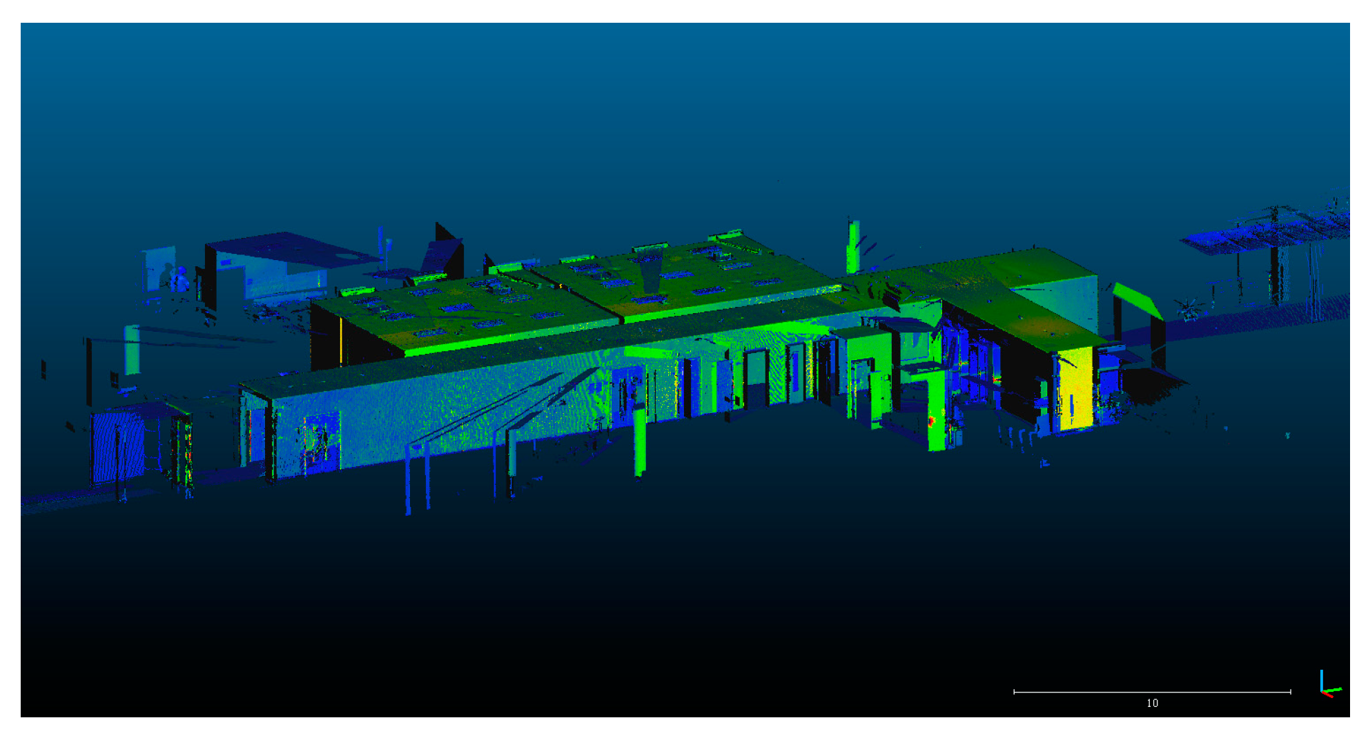
One campus building, including two big rooms and one corridor, was selected as the study site. The data were surveyed from multiple scan stations by a Leica RTC360 scanner. The point cloud data obtained from each station were firstly aligned by the laser scanner during the surveying process, and further refined registration was taken by Leica Cyclone software. The registered point cloud data has a large amount (476 million data points). The positional accuracy of the data points is calculated from the point-to-plane distance using the RANSAC algorithm to fit the plane containing the maximum data points of each dataset. After calculation, the mean and standard deviation of the point-to-plane distance is 0.11 mm and 0.26 mm, respectively. For further data processing, the registered point clouds for the site are approximately 2 million data points after subsampling. The result in Cloudcompare is displayed in Figure 1.
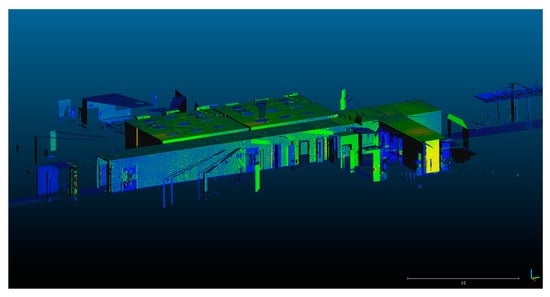
Figure 1.
Original point cloud data set in Cloudcompare.
2.2. Methodology
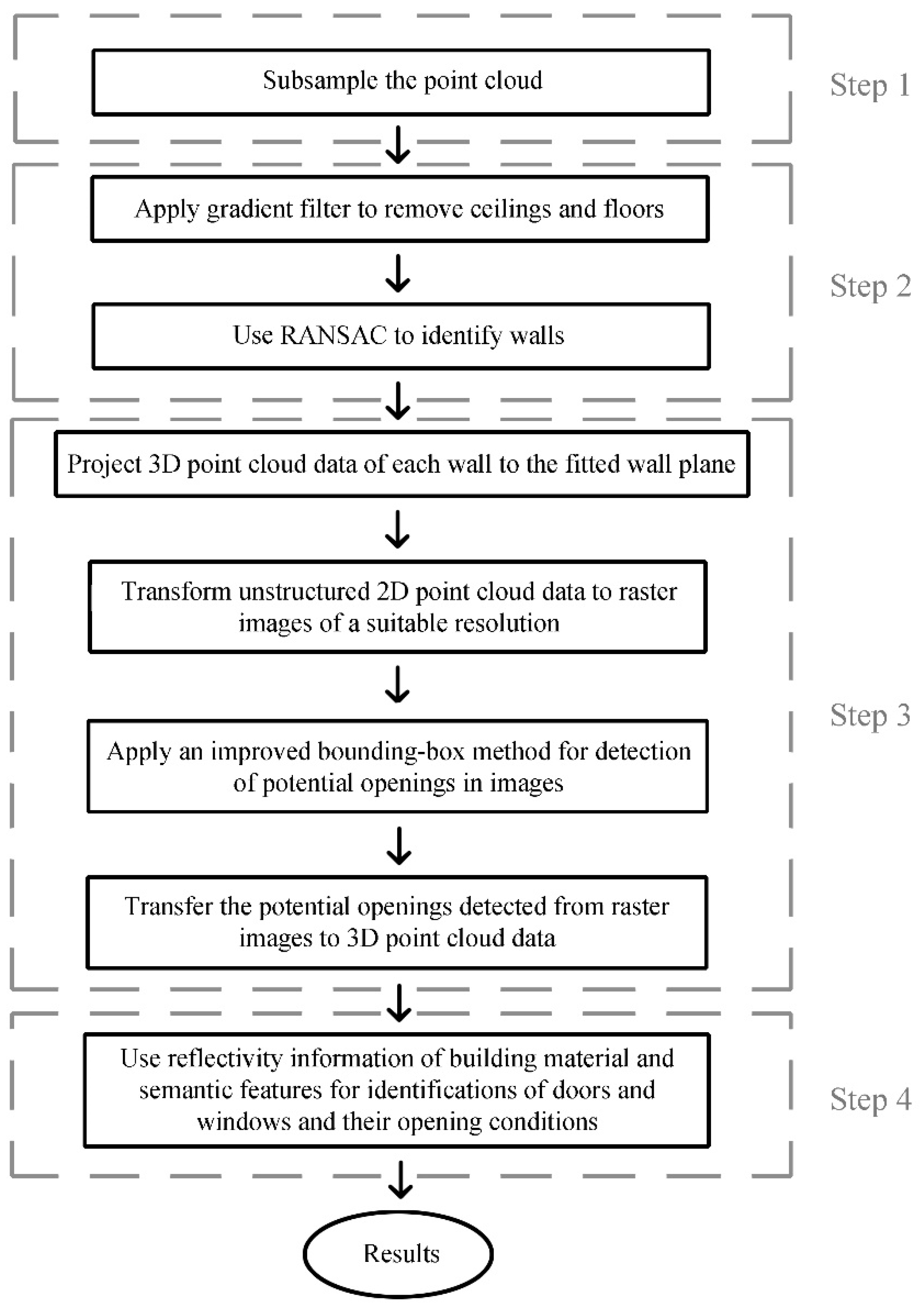
The method mainly includes four steps, as shown in Figure 2. The first step is to subsample the data from 476 million data points to 2 million data points. The second step is the segmentation process, which includes the Gradient Filtering method for removing the horizontal structure part of buildings (ceilings and floor) and the RANSAC algorithm for fitting wall planes from the building structure. The third step is to extract windows and doors (potential openings) from the wall planes, including the projection of 3D data to 2D binary images, and apply the improved Bounding Box algorithm for detecting potential openings. The fourth step is to transform 2D detection results back to 3D, thus differentiating windows and doors and identifying their opening conditions in 3D data.
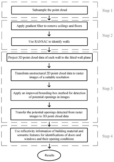
Figure 2.
Schematics of methodology.
The improved Bounding Box algorithm is written as codes in MATLAB. By running the codes in MATLAB to process the point cloud data, the improved Bounding Box algorithm can be applied for detecting potential openings in this paper. Generally, using artificial intelligence approach in windows and doors detection can be performed using Convolutional Neural Network (CNN) for image processing, which uses amounts of images for learning. Since the images for this study are limited, the artificial intelligence approach is not chosen.
This paper introduces several methods for processing the data points and reducing the time consumption, including subsampling the dataset, using the Gradient Filtering method, and using an improved Bounding Box algorithm. Subsampling the dataset can reduce the data density. It can reduce the further processing time as the number of data points has been reduced. The Gradient Filtering method can directly discard the roof and floor part and remain the façade part. Similarly, as the number of data points have been reduced, the further processing time will be reduced. Improved Bounding Box algorithm can minimize the computational resources so as to reduce the processing time.
2.2.1. Data Preprocessing (Step 1)
As the original data is too dense for further processing (476 million data points), subsampling is used to preprocess data points to decrease the number of points to 2 million. The subsampling process is conducted in Cloudcompare software. The ‘spatial mode’ is used as the subsampling method, and the minimum distance between two points is 20 mm. The minimum distance of 20 mm has been tested in Cloudcompare using a wide range of minimum distances for test samples so that the obtained point cloud data density can be successfully fitted to separate planes using RANSAC in step 2.
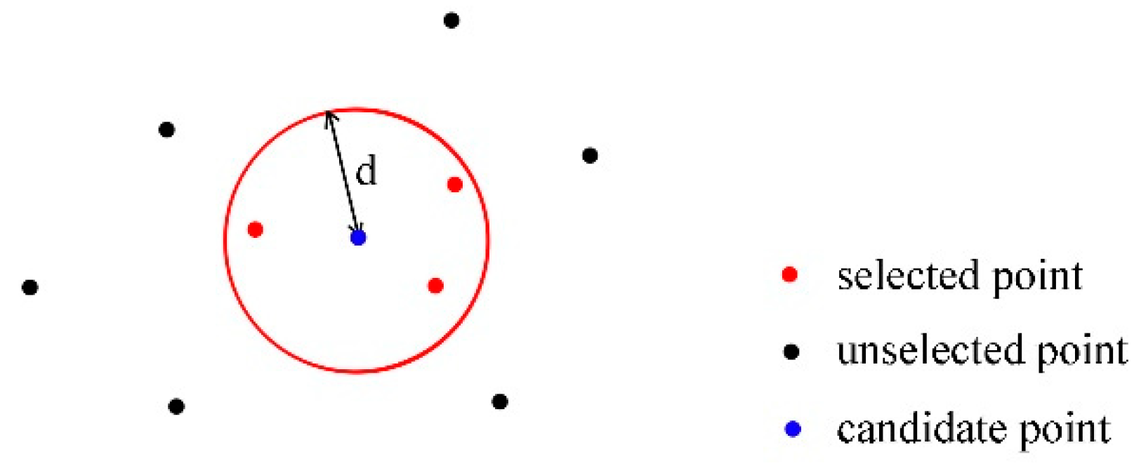
The schematics of subsampling has been shown in Figure 3, where is the minimum distance between two points. When a candidate point (blue point) is used to conduct the distance-based subsampling, a minimum distance will be set by the user to select points having distance to the candidate point less than the minimum distance. These points will be selected points (red points) and the other points having a distance to the candidate point larger than the minimum distance will be unselected points (black points). All the selected points will be eliminated. The process will be conducted for all the points so that the minimum distance between two arbitrary points will be .
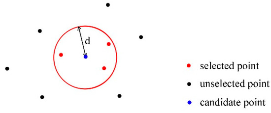
Figure 3.
Schematics of subsampling.
2.2.2. Segmentation Using Gradient Filtering and RANSAC Algorithm (Step 2)
Different from Previtali’s [41] research work using the ray-tracing algorithm, this study used Gradient Filtering, which can discard the floor and ceiling part directly and obtain the wall part of the building within a shorter time. The principle of the Gradient Filtering method is to calculate the gradient value of the scalar field and then filter the data points by gradient value [45,46]. The method for calculating the gradient vector of one point in 3D coordinates is shown in Equation (1).
where , , are the standard unit vectors in the direction of x, y, z coordinates, respectively. is the resultant vector. The method to calculate the gradient value here is to select the gradient value in z direction, which is . The ceiling and roof part will have small gradient value in z direction as they are generally perpendicular to z direction. The façade part will have large gradient value as it is generally parallel to z direction. So, the ceiling and roof part can be selected and discarded by using this method and the façade part can be remained.
Then, by setting RANSAC parameters appropriately, the plane fitting is satisfactory, and the process is efficient (2.424 s from Cloudcompare). The minimum support points per primitive are set to be 500, and the maximum distance of samples to the ideal shape is set to be 0.2 m. The sampling resolution, which represents the distance between neighboring points, is set as 0.1 m. The maximum deviation from the ideal shape average vector is set to be 5°. The overlooking probability, indicating the probability that no other candidate was overlooked during sampling, is set as 0.01 [46].
The principle of RANSAC is as follows: (1) Randomly selecting a subset of data set; (2) Fitting a model to the selected subset; (3) Determining the number of outliners; (4) Repeating steps 1–3 for a prescribed number of iterations. By conducting such steps, the RANSAC can perform a robust estimation of the model parameters.
2.2.3. Windows and Doors Extraction in the 2D Image with Improved Bounding Box Algorithm (Step 3)
Each plane has been rotated to planes parallel to the XOZ plane or the YOZ plane using a rotating matrix. For planes supposed to be parallel to the y-y axis, the rotating matrix should be as follows:
For planes supposed to be parallel to the x-x axis, the rotating matrix should be as follows:
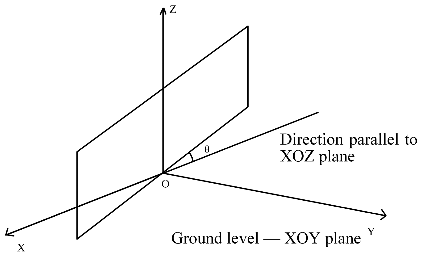
The rotation is based on the theory of the Manhattan World assumption [47] that the common planar primitives and straight lines are intersected orthogonally. Therefore, all the façade planes are assumed to be perpendicular to the XOY plane, which is supposed to be the ground level. Then, the 3D point cloud data will be regulated to 2D point cloud data by rotating the fitted planes to the orientation parallel to the XOZ plane or the YOZ plane. θ is the rotating angle, as shown in Figure 4. After rotating all the planes parallel to the XOZ plane or the YOZ plane, the 3D point cloud data can be directly projected to 2D point cloud data.
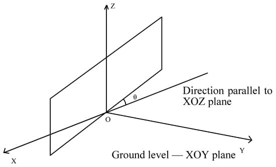
Figure 4.
Rotation angle θ from fitted plane to an orientation parallel to XOZ plane.
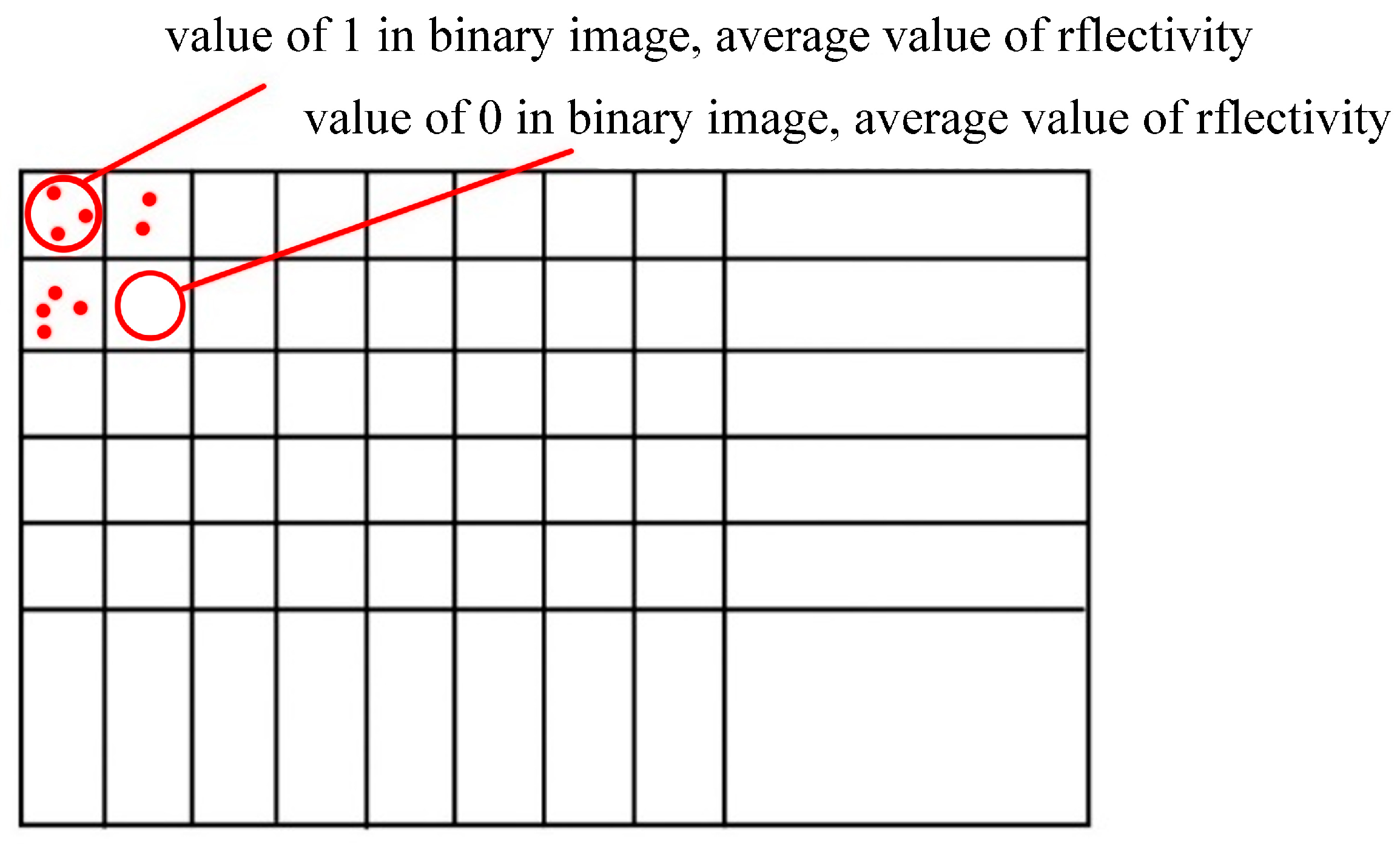
Then, the 2D point cloud data can be transformed into 2D images, as shown in Figure 5. The method here is to define a rectangular box divided into several small square boxes. For instance, the whole 2D point cloud data range from [0, 20] in the X direction and [0, 10] in the Y direction. Then, by dividing the whole 2D area into 200 small squares (20 portions in the X direction and 10 portions in the Y direction), each 2D point cloud data can be sorted into one specific small square box according to the position of the 2D point cloud data. The spectral information (reflectivity) of the small square box is to be determined by averaging the spectral value of the 3D point cloud data sorted into this tiny square box. If there is 2D point cloud data in the small square box, the binary value should be 1. If there is no 2D point cloud data to be classified into this tiny square box, the binary value of this box will be 0.
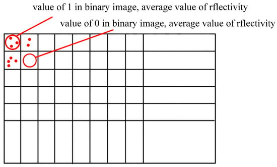
Figure 5.
Schematic drawing of transforming 2D point cloud data to a 2D binary image.
After all the 3D point cloud data have been transformed into 2D images, the extraction of windows and doors can be implemented on the 2D images by using an optimized Bounding Box algorithm. The original Bounding Box algorithm is shown in Equation (2) [48], which returns the location of the fitted rectangle.
where indicates the x location of the initial point; indicates the y location of the initial point; indicates the width of the fitted rectangle; indicates the height of the fitted rectangle for determining the location of windows and doors. The improved Bounding Box algorithm has been used by setting specific parameters based on the building semantic features. The process of setting specific parameters is as follows.
Ameliorate the Boundary Condition of the Bounding Box Algorithm
At the first stage, the detection result of the potential openings is not satisfactory, as most of the bottom boundaries of the doors were not detected. The solution is to eliminate the white space (noise) at the bottom of each plane’s binary image so that the image’s margin can approach the doors’ bottom boundary. To eliminate the image noise, “bwareaopen” removes the minimum area smaller than the threshold value, as shown in Equation (3).
where BW2 means another binary image removing all the connected components with fewer than P pixels from the binary image BW. After testing the result of the “bwareaopen” command, the connect-area parameter P is determined to be set to P = 100.
Elimination of Nonstandard Shape
The nonstandard shapes of windows and doors include shapes with too small or big areas and too high aspect ratio. The elimination of the nonstandard rectangles will be conducted by setting an area threshold value in the programming code that is not to be smaller than 0.9 m2 and not to be larger than 3 m2. In addition, the shape with an aspect ratio (height:width) larger than 3 (3:1) will be considered not to be windows and doors and eliminated.
Region Union Method
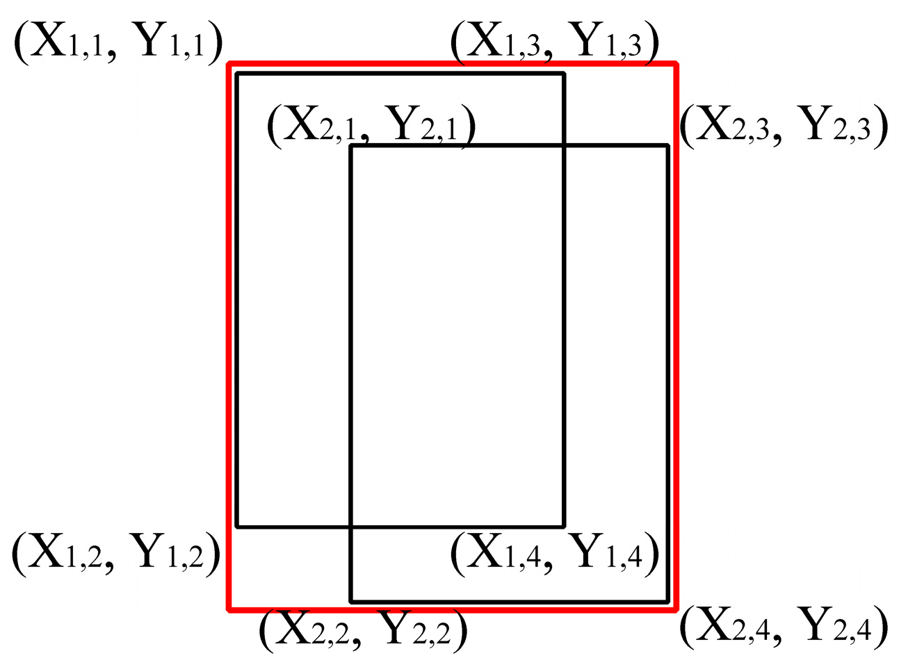
The region union method is developed to solve the specific condition where two rectangles intersect, as shown in Figure 6. Then, the effect of the region union method is to merge the two rectangles to be one rectangle. For instance, if one rectangle with four points , , , intersects with another rectangle with four points , , , , then the merged rectangle will be with four points , , , .
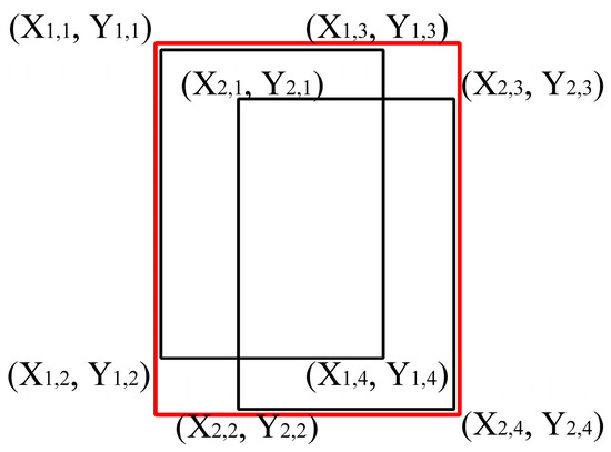
Figure 6.
Schematic drawing of region union method.
Segmentation Method
The effect of the segmentation method is to segment the area composed of rectangles with different levels, which is developed by adding a segmenting line at the juncture of the two modules that are supposed to be partitioned from each other, as shown in Figure 7.

Figure 7.
Schematic drawing for Segmentation method.
Method for Window Detection
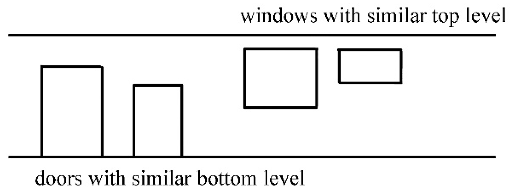
In most cases, doors have similar bottom levels, while windows have similar top levels, as shown in Figure 8. Therefore, it is more reasonable and practical to detect the windows from the top of the building façade. The idea of this study for window detection is to reverse the image plane up and down so that the detection from the bottom can be transversed to detection from the top. Thus, we used the “flipud” command in MATLAB to reverse the image plane to flip vertically.
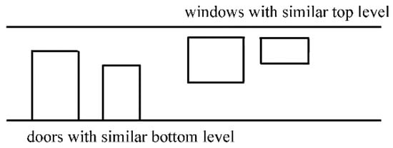
Figure 8.
Schematic features of windows and doors in most cases.
After all the potential openings have been detected, the result of the 2D image will be transformed back to 3D point cloud data by using the inverse rotating matrix, where angle will be the same value as the rotating matrix.
2.2.4. Identification of Windows and Doors and Their Opening Condition (Step 4)
To further conduct the differentiation of windows and doors and identification of their opening condition, this study combines building semantic features and material properties:
- (1)
- If the bottom boundary of the opening is on the ground level, then the opening is supposed to be a door, and the reflectivity of the area needs to be verified.
- (2)
- If the bottom boundary of the opening does not fit the ground level, the material properties will be taken as the primary factor to define whether the detected area is a window, door, or wall. Timber material has reflectivity ranging from 0.2 to 0.35 [46]. White paint on the non-filed concrete has a reflectivity of about 0.6 [49]. Glass has a transmittance of over 0.95 [49]. The scalar field value in Cloudcompare software represents the reflectivity value proportionally. The object having a scalar field value larger than timber material and smaller than white-painted concrete will be regarded as a whiteboard. The overall value relationship will be , where stands for the scalar field value.
For the opening condition, the detection result is based on the rate of the number of the small squares without point cloud data divided by the number of all the small squares (Equation (4)), where one small square is one pixel of the binary image.
If the opening rate is smaller than 0.5, the opening is defined to be closed; if the opening rate is larger than 0.5 and smaller than 0.65, the opening is defined to be half open; if the opening rate is larger than 0.68, the opening is defined to be open.
3. Results
3.1. Results of Gradient Filtering and RANSAC Algorithm
The steps mentioned in Section 2 were realized in MATLAB codes that run in a computer with Windows 10 system (64-bits), an Intel Core i5-3317U processor, and 16 GB RRD3 RAM. Gradient Filtering was applied to the site data to discard the ceilings and floors of the building. The post-filtering dataset is shown in Figure 9.

Figure 9.
The ceiling and (a) floor part (left); and (b) wall part (right) to be separated using Gradient Filtering.
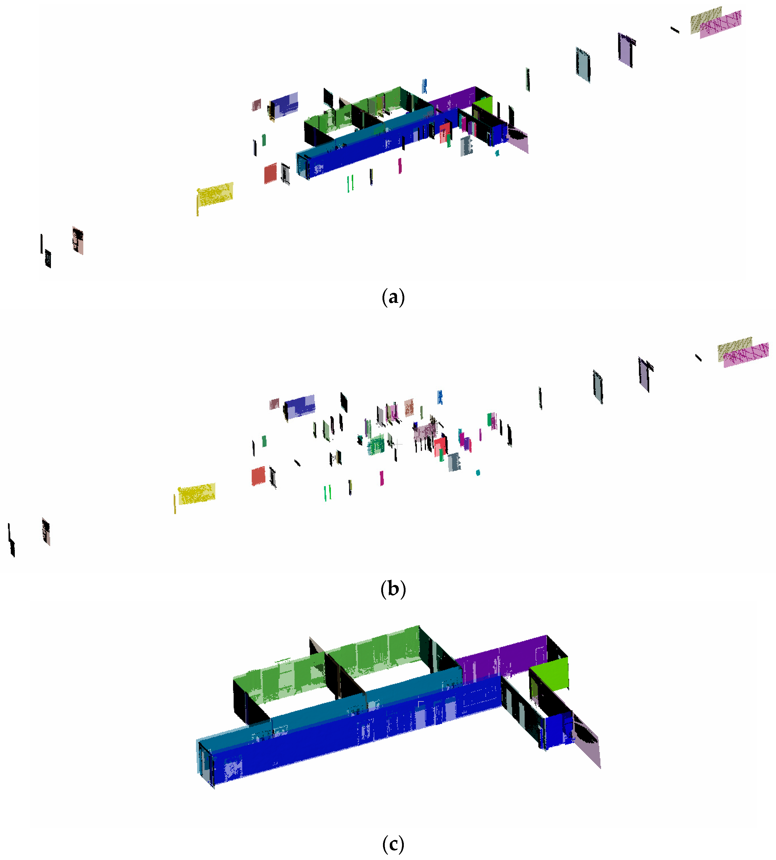
The RANSAC shape detection results are shown in Figure 10. Using RANSAC, indoor obstacles (desks and chairs) have been directly discarded. After deleting indoor noise data (Figure 10b) manually, the planes left can be used for further analysis, as shown in Figure 10c. The maximum distance of samples to the ideal shape has been set to larger than the offset of windows and doors from the wall plane so that the data of windows and doors can be reserved within the wall plane.
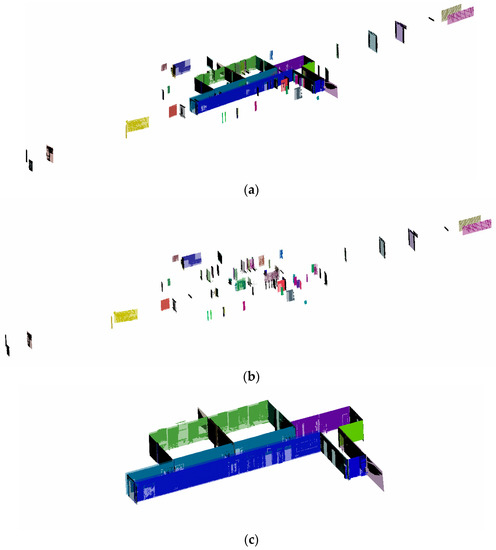
Figure 10.
RANSAC (a) planes fit result (up); (b) planes deleted manually (middle); (c) planes for further processing (down).
3.2. Results of Windows and Doors Detection on 2D Image
3.2.1. Ameliorate Boundary Condition and Adopt Nonstandard Shape Elimination and Region Union Method
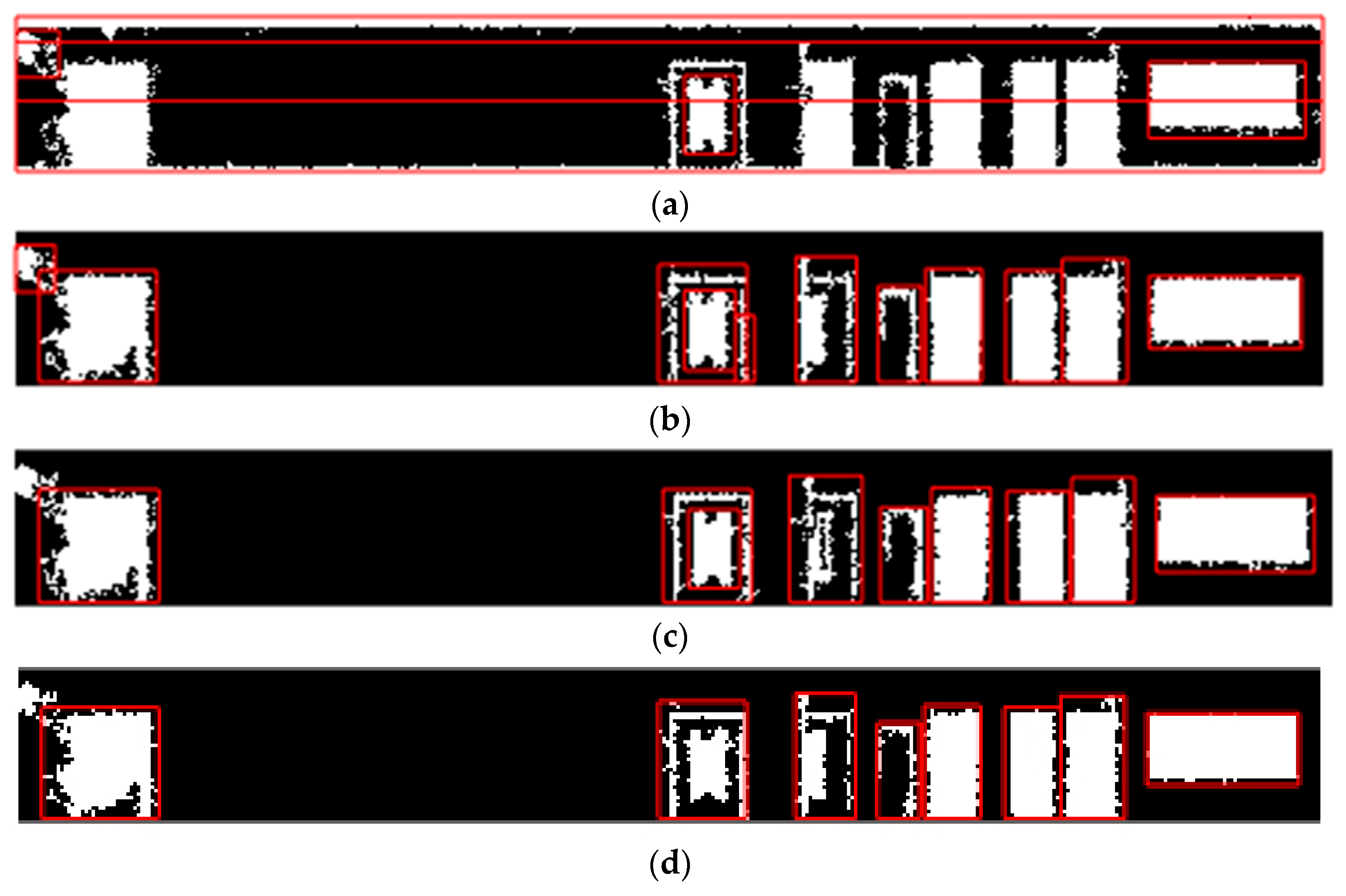
The same grammar rules were applied to all the façade planes for door detection, and one specific rule was applied to Plane 6 and Plane 27 for windows detection. For ease of demonstration, Plane 1 was used as an example to present each step’s output of door detection. The primary result is shown in Figure 11a, where the detected box selected the whole area as the potential opening. The main reason for the unsatisfactory result was that the boundary condition of the image was not ideal and needed to be improved on the ground level. After improving the boundary condition of the Plane 1 binary image, the detection results are shown in Figure 11b. There is still a small-sized rectangle that is not the normal size of windows and doors, which need to be eliminated. After applying the elimination of rectangles with nonstandard shapes, the detection results can be shown in Figure 11c. The normal size of the building openings is determined. However, the detected openings intersected, which needs to be tackled. Then, the union region method was proposed, and the satisfactory post-processing result is shown in Figure 11d. Since the segmentation method and elimination of openings with a high aspect ratio do not affect Plane 1’s detection, the demonstration of the two methods will be conducted on Plane 8.
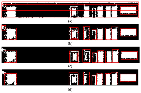
Figure 11.
(a) Original detection of windows and doors on Plane 1; (b) detection of windows and doors after adopting the boundary approximation method; (c) detection of windows and doors by eliminating small-sized rectangles for Plane 1; (d) detection of windows and doors for Plane 1 after union region method.
3.2.2. Adopt Segmentation Method and Elimination of High Aspect Ratio Openings
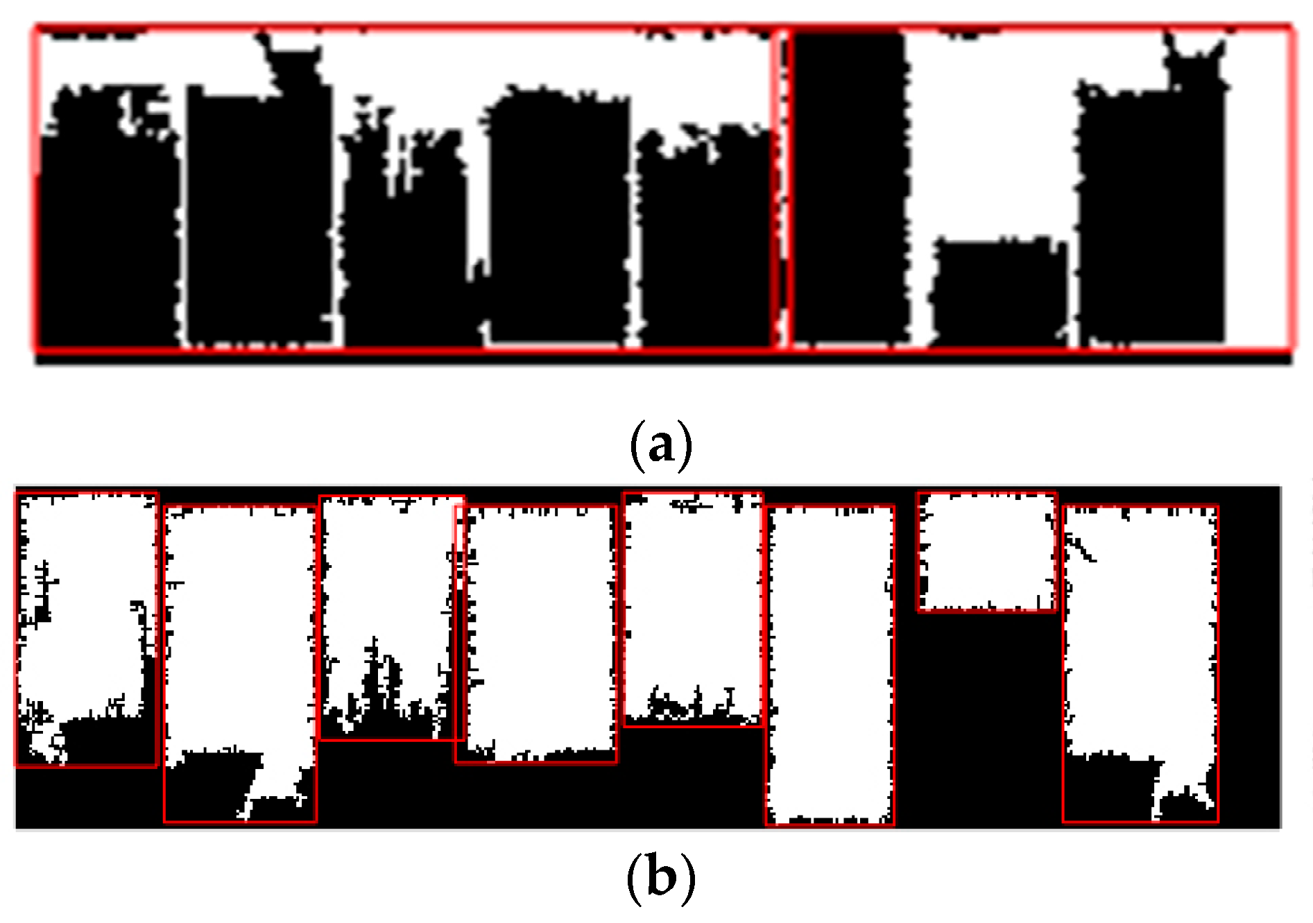
Figure 12a shows the detection result on Plane 8 after using the same grammar rules as Plane 1, where two potential openings were detected as one. Figure 12b displays the result after adopting the segmentation method, where two potential openings were segmented successfully. Still, one rectangular shape with high aspect detected as a potential opening is not correctly detected. By eliminating of high aspect ratio of 3 (height:width = 3:1), the final detection result is shown in Figure 12c. All planes except for Plane 5 and Plane 27 applied the same grammar rules for door detection, and Planes 5 and 27 used the inverse method for windows detection.

Figure 12.
(a) Results of original Plane 8 (left); (b) after adopting Segmentation method (middle); (c) after adopting elimination of high aspect ratio (right).
3.2.3. Adopt Specific Method for Windows Detection
Plane 5 was taken as an example to present the rule for windows detection. The result of using the same grammar rules of door detection is displayed in Figure 13a, where none of the windows have been detected. After reversing the binary image from up to down, the detection result is shown in Figure 13b, where all the potential openings have been detected.
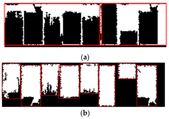
Figure 13.
Results of original Plane 5 (a) and after adopting reversing binary image (b).
3.3. Results of Windows and Doors Differentiation and Opening Condition on 3D Point Cloud Data
Building material properties and semantic features were applied to 3D point cloud data detection for further differentiating windows and doors. Moreover, the opening condition is judged by calculating the opening rate defined in Section 2.2.4.
3.3.1. Windows and Doors Detection Result on 3D Point Cloud of Each Plane
Figure 14 shows the detection result of Plane 1. The detected location of the first door on the plane’s left side is correct, but the opening condition is wrong. The door should be closed, but the model’s detection opens it. The missing data points probably cause the detection mistake.

Figure 14.
Detection with material and opening condition on 3D point cloud of Plane 1.
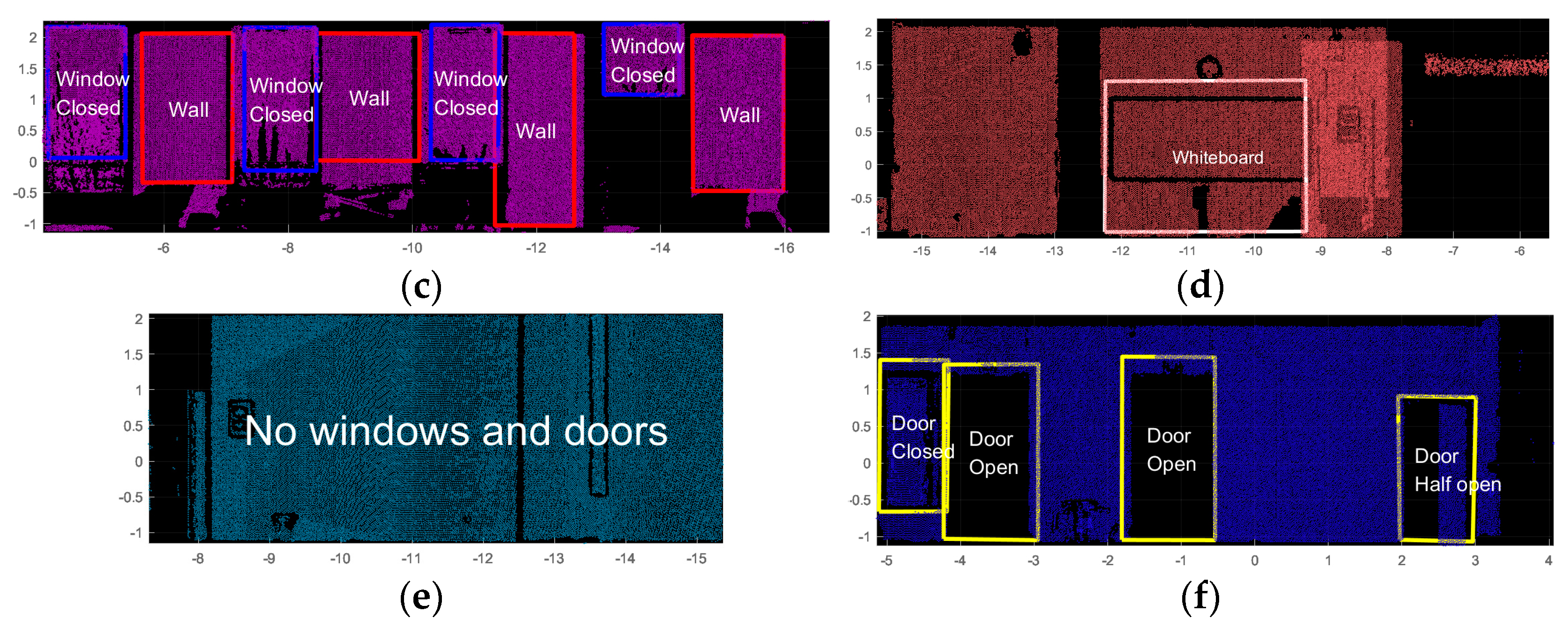
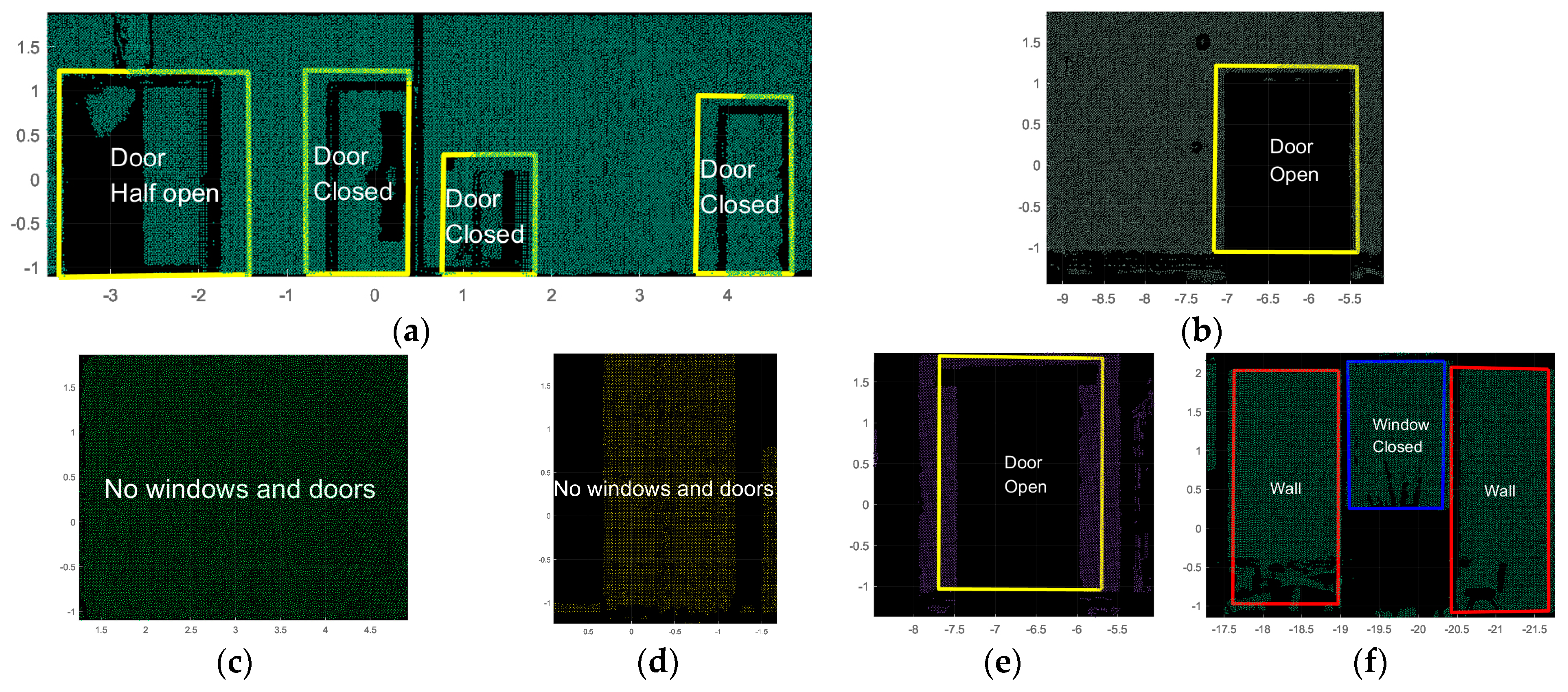
The detection result of Plane 2 is displayed in Figure 15. The third door from the left should be detected as closed, but the detection result is half open. The main reason for the mistake is similar to Plane 1, for missing data points. The material type is all correct. The rest of the results are shown in Figure 16 and Figure 17, where all the material type and opening conditions are correct, except for that Plane 6’s framed size of the whiteboard is larger than the real size.

Figure 15.
Detection with material and opening condition on 3D point cloud of Plane 2.

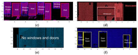
Figure 16.
Detection with material and opening condition on 3D point cloud of (a) Plane 3; (b) Plane 4; (c) Plane 5; (d) Plane 6; (e) Plane 7; (f) Plane 8.
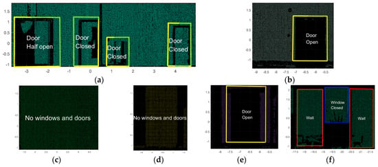
Figure 17.
Detection with material and opening condition on 3D point cloud of (a) Plane 9; (b) Plane 10; (c) Plane 11; (d) Plane 12; (e) Plane 13; (f) Plane 27.
3.3.2. Final Result Shown in MATLAB Window
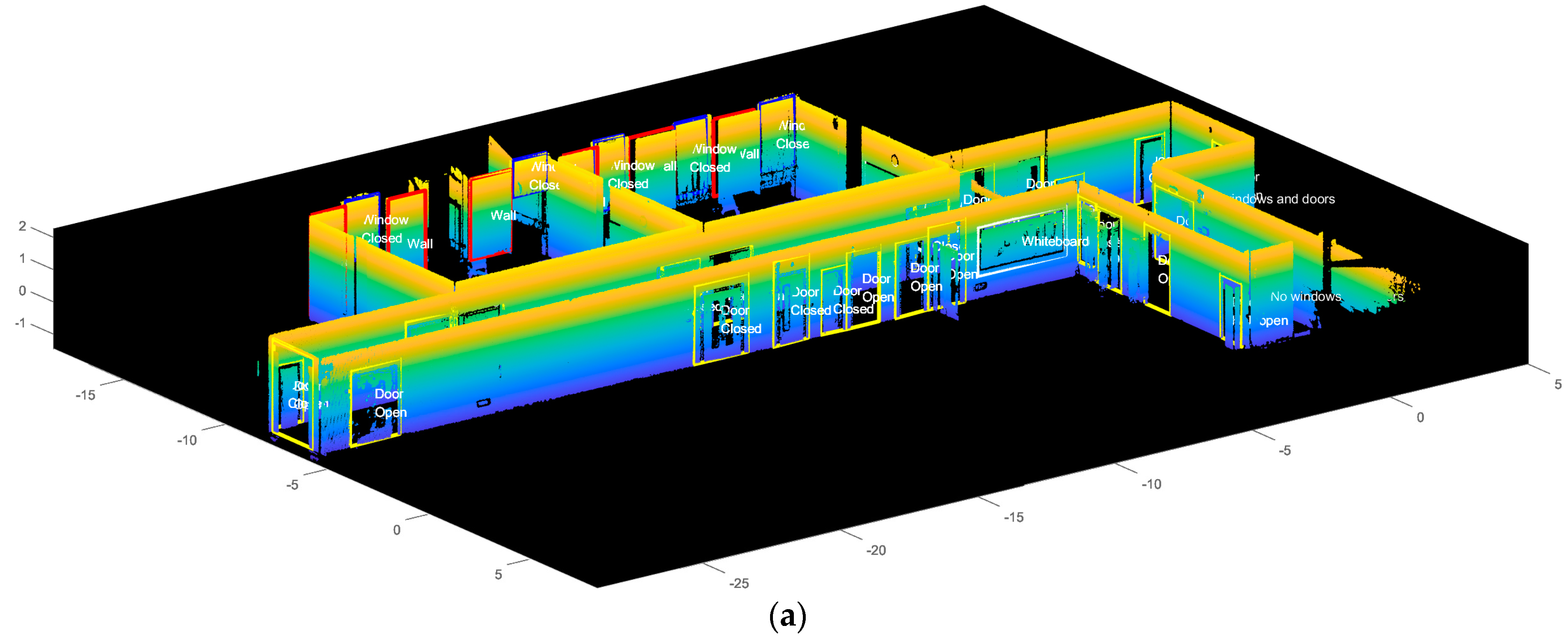
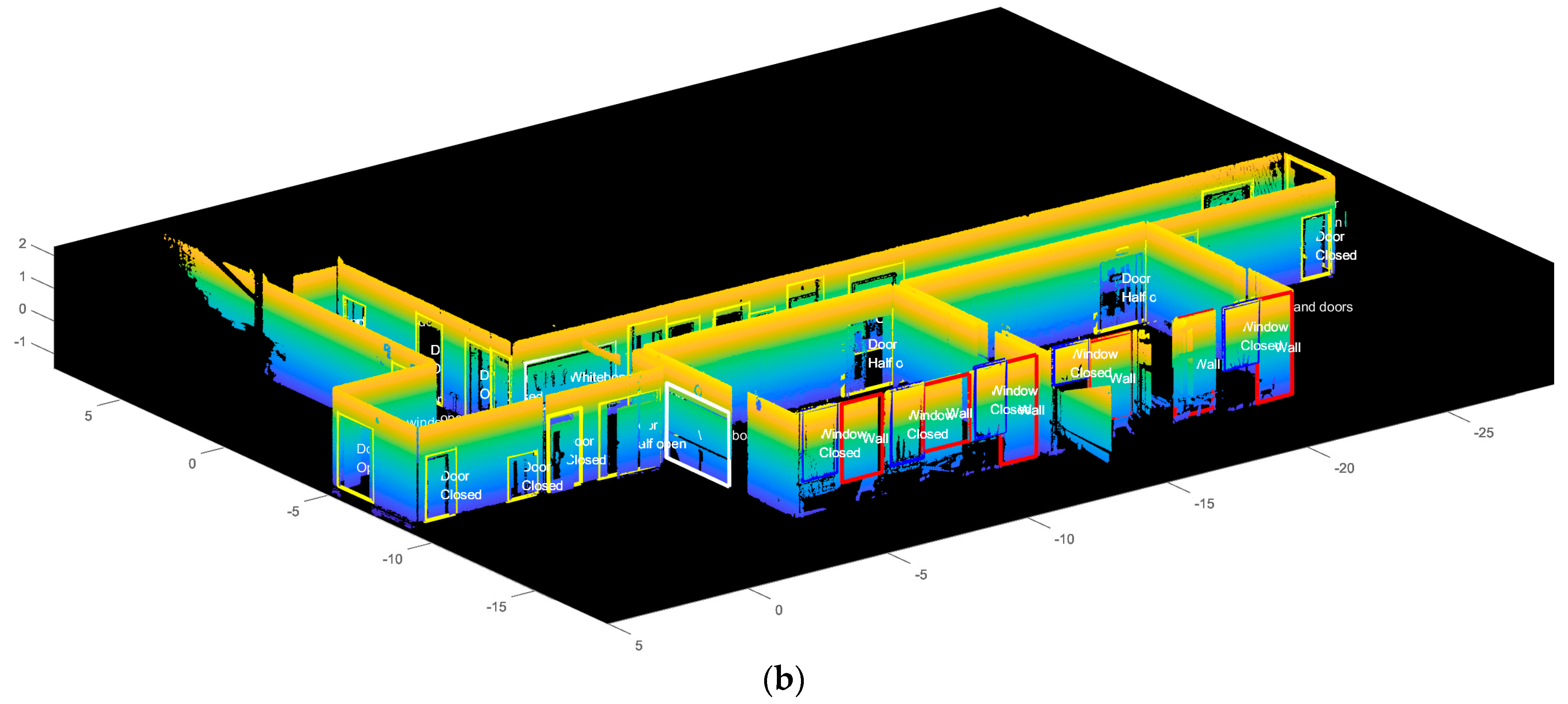
The perspective views of the overall windows and doors detection of the building façade have been displayed in Figure 18. To have a good view of the results, doors are marked yellow; windows are marked blue; whiteboards are marked white; and walls are marked red.
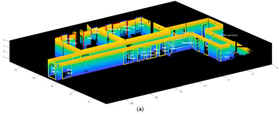
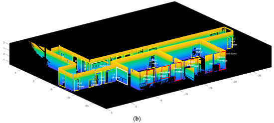
Figure 18.
Overall detection of windows and doors of perspective (a) view 1; (b) view 2.
To evaluate the performance of our framework, we computed two final evaluation indexes, completeness (Equation (5)) and correctness (Equation (6)), related to the quality of feature extraction.
where , , are the number of detected potential openings, correctly detected potential openings, and potential openings that should be detected. The corresponding quality performance is shown respectively in Table 1 and Table 2.

Table 1.
Table of completeness.

Table 2.
Table of correctness.
The completion of the model detection reaches 100%, and the correctness of the model reaches 90.32%. The programming speed is fast for only 22.8 s, including the time cost by reading the point cloud data of 10.319 s and the time cost by showing the data result of 4.938 s. The time cost for the segmentation process is 40.862 s and the time cost for the feature extraction process is 7.543 s. The processing time and the differentiation effect is generally more efficient than other existing method in the literature. Table 3 shows a comparison of computational efficiency with other existing methods in the literature.

Table 3.
Comparison of computational efficiency with other method.
4. Conclusions
This paper introduced the improved Bounding Box algorithm to detect potential openings from building façade, where the detection of potential openings can help build 3D building information models that can be used to improve construction efficiency. The method involves three main steps. Firstly, each façade is roughly segmented using the Gradient Filtering method and RANSAC algorithm. Secondly, the segmented façade planes are transformed into 2D images. Methods including eliminating nonstandard shape, region union, and segmentation are adopted to extract potential openings on 2D images. Thirdly, the detection result from each image is transformed back to 3D data. Material reflectivity is used to differentiate windows and doors, and the opening ratio is calculated to identify the opening conditions. The improved Bounding Box algorithm represents advantages with respect to the following: (1) accurately extracting and differentiating windows and doors; (2) minimizing the computational resources needed; (3) detecting the opening condition and the material property of the openings. The speed of the programming model is generally fast. The preprocessing process for subsampling the dataset and segmentation process totally takes 40.862 s. The time cost for feature extraction process is only 7.543 s, excluding the time cost of reading data of 10.319 s and the time cost of showing data of 4.938 s. By calculation, the completeness of the feature extraction is 100% and the correctness is 90.32%. In future research, the number of read-in points needs to be tested to obtain the optimal result for each plane of the dataset so that the parameters of the Bounding Box used for detecting windows and doors can be set to be in a more robust range.
Author Contributions
Conceptualization, B.C., S.C. and L.F.; methodology, B.C., S.C., L.F. and Y.C.; software, S.C.; validation, S.C., B.C. and Y.L.; formal analysis, B.C. and S.C.; resources, L.F. and Y.C.; data curation, S.C.; writing—original draft preparation, B.C., S.C., L.F. and Z.L.; writing—review and editing, B.C., S.C., Y.L. and Z.L.; supervision, L.F.; project administration, B.C.; funding acquisition, B.C. All authors have read and agreed to the published version of the manuscript.
Funding
This research was funded by BIM Engineering Center of Anhui Province, grant number AHBIM2021KF01; Fundamental Funds for the Central Universities of Central South University, grant number 2021zzts0245; and National Natural Science Foundation of China, China, grant number 72171237.
Institutional Review Board Statement
No applicable.
Informed Consent Statement
No applicable.
Data Availability Statement
The datasets generated during and/or analyzed during the current study are available from the corresponding author on reasonable request.
Conflicts of Interest
The authors declare no conflict of interest.
References
- Guo, S.; Xiong, H.J.; Zheng, X.W. A Novel Semantic Matching Method for Indoor Trajectory Tracking. ISPRS Int. Geo-Inf. 2017, 6, 17. [Google Scholar] [CrossRef]
- Liu, M.Y.; Chen, R.Z.; Li, D.R.; Chen, Y.J.; Guo, G.Y.; Cao, Z.P.; Pan, Y.J. Scene Recognition for Indoor Localization Using a Multi-Sensor Fusion Approach. Sensors 2017, 17, 20. [Google Scholar] [CrossRef]
- Nikoohemat, S.; Diakite, A.A.; Zlatanova, S.; Vosselman, G. Indoor 3D reconstruction from point clouds for optimal routing in complex buildings to support disaster management. Autom. Constr. 2020, 113, 17. [Google Scholar] [CrossRef]
- Ma, G.F.; Wu, Z.J. BIM-based building fire emergency management: Combining building users’ behavior decisions. Autom. Constr. 2020, 109, 16. [Google Scholar] [CrossRef]
- Wang, R.S.; Xie, L.; Chen, D. Modeling Indoor Spaces Using Decomposition and Reconstruction of Structural Elements. Photogramm. Eng. Remote Sens. 2017, 83, 827–841. [Google Scholar] [CrossRef]
- Heaton, J.; Parlikad, A.K.; Schooling, J. Design and development of BIM models to support operations and maintenance. Comput. Ind. 2019, 111, 172–186. [Google Scholar] [CrossRef]
- Portales, C.; Lerma, J.L.; Navarro, S. Augmented reality and photogrammetry: A synergy to visualize physical and virtual city environments. Isprs J. Photogramm. Remote Sens. 2010, 65, 134–142. [Google Scholar] [CrossRef]
- Jung, J.; Stachniss, C.; Ju, S.; Heo, J. Automated 3D volumetric reconstruction of multiple-room building interiors for as-built BIM. Adv. Eng. Inform. 2018, 38, 811–825. [Google Scholar] [CrossRef]
- Iman Zolanvari, S.M.; Laefer, D.F. Slicing Method for curved façade and window extraction from point clouds. ISPRS J. Photogramm. Remote Sens. 2016, 119, 334–346. [Google Scholar] [CrossRef]
- Resop, J.; Hession, W. Terrestrial Laser Scanning for Monitoring Streambank Retreat: Comparison with Traditional Surveying Techniques. J. Hydraul. Eng. 2010, 136, 794–798. [Google Scholar] [CrossRef]
- Fan, L.; Powrie, W.; Smethurst, J.; Atkinson, P.M.; Einstein, H. The effect of short ground vegetation on terrestrial laser scans at a local scale. Isprs J. Photogramm. Remote Sens. 2014, 95, 42–52. [Google Scholar] [CrossRef]
- Abayowa, B.O.; Yilmaz, A.; Hardie, R.C. Automatic registration of optical aerial imagery to a LiDAR point cloud for generation of city models. Isprs J. Photogramm. Remote Sens. 2015, 106, 68–81. [Google Scholar] [CrossRef]
- Park, M.K.; Lee, S.J.; Lee, K.H. Multi-scale tensor voting for feature extraction from unstructured point clouds. Graph. Model. 2012, 74, 197–208. [Google Scholar] [CrossRef]
- Ma, Y.; Wei, Z.; Wang, Y. Point Cloud Feature Extraction Based Integrated Positioning Method for Unmanned Vehicle. Appl. Mech. Mater. 2014, 590, 463–469. [Google Scholar] [CrossRef]
- Cheng, B.; Fu, H.; Li, T.; Zhang, H.; Huang, J.; Peng, Y.; Chen, H.; Fan, C. Evolutionary computation-based multitask learning network for railway passenger comfort evaluation from EEG signals. Appl. Soft Comput. 2023, 110079. [Google Scholar] [CrossRef]
- Cheng, B.; Chang, R.; Yin, Q.; Li, J.; Huang, J.; Chen, H. A PSR-AHP-GE model for evaluating environmental impacts of spoil disposal areas in high-speed railway engineering. J. Clean. Prod. 2023, 388, 135970. [Google Scholar] [CrossRef]
- Fu, H.; Niu, J.; Wu, Z.; Cheng, B.; Guo, X.; Zuo, J. Exploration of public stereotypes of supply-and-demand characteristics of recycled water infrastructure - Evidence from an event-related potential experiment in Xi’an, China. J. Environ. Manag. 2022, 322, 116103. [Google Scholar] [CrossRef]
- Schnabel, R.; Wahl, R.; Klein, R. Efficient RANSAC for point-cloud shape detection. Comput. Graph. Forum 2007, 26, 214–226. [Google Scholar] [CrossRef]
- Awwad, T.M.; Zhu, Q.; Du, Z.Q.; Zhang, Y.T. An improved segmentation approach for planar surfaces from unstructured 3D point clouds. Photogramm. Rec. 2010, 25, 5–23. [Google Scholar] [CrossRef]
- Fischler, M.A.; Bolles, R.C. Random Sample Consensus—A Paradigm For Model-Fitting With Applications to Image-Analysis and Automated Cartography. Commun. ACM 1981, 24, 381–395. [Google Scholar] [CrossRef]
- Boulaassal, H.; Landes, T.; Grussenmeyer, P. Automatic Extraction of Planar Clusters and Their Contours on Building Façades Recorded by Terrestrial Laser Scanner. Int. J. Arch. Comput. 2009, 7, 1–20. [Google Scholar] [CrossRef]
- Wang, M.; Tseng, Y.-H. LIDAR data segmentation and classification based on octree structure. parameters 2004. [Google Scholar]
- Lari, Z.; Habib, A. An adaptive approach for the segmentation and extraction of planar and linear/cylindrical features from laser scanning data. Isprs J. Photogramm. Remote Sens. 2014, 93, 192–212. [Google Scholar] [CrossRef]
- Mahmoudabadi, H.; Olsen, M.J.; Todorovic, S. Efficient terrestrial laser scan segmentation exploiting data structure. ISPRS J. Photogramm. Remote Sens. 2016, 119, 135–150. [Google Scholar] [CrossRef]
- Che, E.; Olsen, M.J. Multi-scan segmentation of terrestrial laser scanning data based on normal variation analysis. ISPRS J. Photogramm. Remote Sens. 2018, 143, 233–248. [Google Scholar] [CrossRef]
- Luo, H.; Khoshelham, K.; Fang, L.; Chen, C. Unsupervised scene adaptation for semantic segmentation of urban mobile laser scanning point clouds. ISPRS J. Photogramm. Remote Sens. 2020, 169, 253–267. [Google Scholar] [CrossRef]
- Chen, J.; Kira, Z.; Cho, Y.K. LRGNet: Learnable Region Growing for Class-Agnostic Point Cloud Segmentation. IEEE Robot. Autom. Lett. 2021, 6, 2799–2806. [Google Scholar] [CrossRef]
- Zhang, C.; Fan, H. An Improved Multi-Task Pointwise Network for Segmentation of Building Roofs in Airborne Laser Scanning Point Clouds. Photogramm. Rec. 2022, 37, 260–284. [Google Scholar] [CrossRef]
- Bendels, G.H.; Schnabel, R.; Klein, R. Detecting Holes in Point Set Surfaces. In Proceedings of the 14th International Conference in Central Europe on Computer Graphics, Visualization and Computer Vision, Univ W Bohemia, Campus Bory, Plzen Bory, Czech Republic, 30 January–3 February 2006; pp. 89–96. [Google Scholar]
- Pu, S.; Vosselman, G. Automatic extraction of building features from terrestrial laser scanning. Int. Arch. Photogramm. Remote Sens. Spat. Inf. Sci. 2012, 36. [Google Scholar]
- Linh, T.H.; Laefer, D.F.; Hinks, T.; Carr, H. Flying Voxel Method with Delaunay Triangulation Criterion for Facade/Feature Detection for Computation. J. Comput. Civil. Eng. 2012, 26, 691–707. [Google Scholar] [CrossRef]
- Truong-Hong, L.; Laefer, D.F.; Hinks, T.; Carr, H. Combining an Angle Criterion with Voxelization and the Flying Voxel Method in Reconstructing Building Models from LiDAR Data. Comput. Aided Civ. Infrastruct. Eng. 2013, 28, 112–129. [Google Scholar] [CrossRef]
- Linh, T.H.; Laefer, D.F. Octree-based, automatic building facade generation from LiDAR data. Comput. Aided Des. 2014, 53, 46–61. [Google Scholar] [CrossRef]
- Ni, H.; Lin, X.; Ning, X.; Zhang, J. Edge Detection and Feature Line Tracing in 3D-Point Clouds by Analyzing Geometric Properties of Neighborhoods. Remote Sens. 2016, 8, 710. [Google Scholar] [CrossRef]
- Li, Z.; Zhang, L.; Mathiopoulos, P.T.; Liu, F.; Zhang, L.; Li, S.; Liu, H. A hierarchical methodology for urban facade parsing from TLS point clouds. ISPRS J. Photogramm. Remote Sens. 2017, 123, 75–93. [Google Scholar] [CrossRef]
- Shi, S.; Wang, X.; Li, H. PointRCNN: 3D Object Proposal Generation and Detection From Point Cloud. In Proceedings of the 2019 IEEE/CVF Conference on Computer Vision and Pattern Recognition (CVPR), Long Beach, CA, USA, 15–20 June 2019; pp. 770–779. [Google Scholar]
- Shao, J.; Zhang, W.; Shen, A.; Mellado, N.; Cai, S.; Luo, L.; Wang, N.; Yan, G.; Zhou, G. Seed point set-based building roof extraction from airborne LiDAR point clouds using a top-down strategy. Autom. Constr. 2021, 126, 103660. [Google Scholar] [CrossRef]
- Otepka, J.; Ghuffar, S.; Waldhauser, C.; Hochreiter, R.; Pfeifer, N. Georeferenced Point Clouds: A Survey of Features and Point Cloud Management. ISPRS Int. Geo-Inf. 2013, 2, 1038–1065. [Google Scholar] [CrossRef]
- Previtali, M.; Barazzetti, L.; Brumana, R.; Cuca, B.; Oreni, D.; Roncoroni, F.; Scaioni, M. Automatic façade modelling using point cloud data for energy-efficient retrofitting. Appl. Geomat. 2014, 6, 95–113. [Google Scholar] [CrossRef]
- Malihi, S.; Zoej, M.J.V.; Hahn, M.; Mokhtarzade, M. Window Detection from UAS-Derived Photogrammetric Point Cloud Employing Density-Based Filtering and Perceptual Organization. Remote Sens. 2018, 10, 22. [Google Scholar] [CrossRef]
- Previtali, M.; Díaz Vilariño, L.; Scaioni, M. Towards Automatic Reconstruction of Indoor Scenes from Incomplete Point Clouds: Door and Window Detection and Regularization. ISPRS Int. Arch. Photogramm. Remote Sens. Spat. Inf. Sci. 2018, XLII-4, 507–514. [Google Scholar] [CrossRef]
- Jarzabek-Rychard, M.; Lin, D.; Maas, H.G. Supervised Detection of Facade Openings in 3D Point Clouds with Thermal Attributes. Remote Sens. 2020, 12, 17. [Google Scholar] [CrossRef]
- Zhao, M.N.; Hua, X.H.; Feng, S.Q.; Zhao, B.F. Information Extraction of Buildings, Doors, and Windows Based on Point Cloud Slices. Chin. J. Lasers 2020, 47, 10. [Google Scholar] [CrossRef]
- Cai, Y.Z.; Fan, L. An Efficient Approach to Automatic Construction of 3D Watertight Geometry of Buildings Using Point Clouds. Remote Sens. 2021, 13, 18. [Google Scholar] [CrossRef]
- Fukunaga, K.; Hostetler, L. The estimation of the gradient of a density function, with applications in pattern recognition. IEEE Trans. Inf. Theory 1975, 21, 32–40. [Google Scholar] [CrossRef]
- CloudCompare v2.6.1–User Manual. Available online: http://www.cloudcompare.org/doc/qCC/CloudCompare%20v2.6.1%20-%20User%20manual.pdf (accessed on 2 January 2023).
- Coughlan, J.; Yuille, A. In Proceedings of the Manhattan World: Compass Direction from a Single Image by Bayesian Inference, Kerkyra, Greece, 20–27 September 1999.
- Torr, P.H.S.; Zisserman, A. MLESAC: A New Robust Estimator with Application to Estimating Image Geometry. Comput. Vis. Image Underst. 2000, 78, 138–156. [Google Scholar] [CrossRef]
- Approximate Reflectance Values of Typical Building Finishes. 2018. Available online: https://decrolux.com.au/learning-centre/2018/approximate-reflectance-values-of-typical-building-finishes (accessed on 2 January 2023).
Disclaimer/Publisher’s Note: The statements, opinions and data contained in all publications are solely those of the individual author(s) and contributor(s) and not of MDPI and/or the editor(s). MDPI and/or the editor(s) disclaim responsibility for any injury to people or property resulting from any ideas, methods, instructions or products referred to in the content. |
© 2023 by the authors. Licensee MDPI, Basel, Switzerland. This article is an open access article distributed under the terms and conditions of the Creative Commons Attribution (CC BY) license (https://creativecommons.org/licenses/by/4.0/).

