1. Introduction
Micropiles are cast-in-place bored piles with a diameter smaller than 300 mm. Dr. Fernando Lizzi, an Italian civil engineer, proposed the idea of using such piles to repair buildings in the early 1950s, and since then, micropiles have been used extensively in Europe for structural repair and stabilization [
1]. However, it was not until 1973 that micropiles were first used in North America in several underpinning projects in the areas of Boston and New York. Following this, the use of micropiles has become widespread. Micropiles can be installed easily in pre-existing foundations by boring holes to the desired depth through the reinforced concrete and then filling them with cement grout and the necessary steel reinforcement. Thanks to technological advances in the field of drilling, micropiles can now be installed at almost any angle, through any ground type, with minimal noise and disturbance. Due to the small size of modern drilling equipment, underpinning existing foundations is possible even in tight spaces [
2,
3,
4,
5].
The increasing number of buildings affected by excessive settlement or tilt has resulted in a growing need for an improved understanding of the methods of repairing existing foundations. The tilting of an entire building usually occurs because of applied contact (bearing) stresses that exceed the bearing capacity of the soil supporting the foundations. In addition, overestimating the soil bearing capacity or failing to conduct a proper geotechnical investigation can lead to a poorly designed foundation, causing later settlement issues.
Several researchers tried to assess the improvement in the vertical behavior of existing foundations underpinned with micropiles through experimental and numerical analyses. For example, El Kamash and Han [
6] conducted a numerical investigation using the finite-difference software FLAC3D. The vertical displacement of the raft was found to decrease with the increase in micropiles length. Azzam and Basha [
7] examined the advantages of installing micropiles in parallel rows on both sides of a strip footing under a newly added area. The underpinning process proved to be effective in increasing the bearing capacity of the strip footing by 260%.
The use of micropiles in retrofitting applications, not only in the underpinning of rafts but also in primary foundation systems, has already attracted extensive research [
8,
9,
10,
11,
12]. Micropiles can likewise be used as a form of vertical or inclined soil reinforcement. A growing body of evidence confirms that installing unconnected micropiles under or around footings can increase the soil bearing capacity [
13,
14,
15,
16,
17]. Babu et al. [
15] presented a method for increasing the load-bearing capacity of the foundation soil of a two-story building in India by using micropiles to reinforce the soil.
Previous studies have described numerous case histories that demonstrate the successful use of micropiles to repair existing footings. For instance, Cadden et al. [
16] reported some of the most well-known historical cases, from 1995 to 2003, where micropiles were used to underpin existing foundations. AbdelSalam [
17] described a micropile repair system for a tilted building supported on deep soft clay in Alexandria, Egypt. The repair system included sixty micropiles to stabilize the 16-story building. Case studies of two inclined structures in Egypt, with 11 and 13 stories, were presented by Elgamal [
18] and Bakr [
19], respectively. A total of 89 micropiles, measuring 20 cm in diameter and 20 m in length with an axial capacity of 250 kN, were used to rehabilitate the 11-story building. For the 13-story building, it was necessary to increase the raft foundation load capacity by 7200 kN. For this purpose, 36 micropiles, measuring 15 cm in diameter and 13 m in length with an axial capacity of 200 kN, were installed in 20 days.
Gutierrez [
20] described the strengthening of the existing foundations of an Arts and Science Museum by installing 62 micropiles with a compression capacity of 250 kN each, to accommodate the needs of the museum. The first documented case history of micropiling existing in shallow foundations in China concerned an old 3-story building that needed to support additional applied vertical loads resulting from the construction of two more floors [
6].
Three micropile retrofitting cases were discussed by Edens and Fisher [
21]. In the first project, 36 micropiles were used to repair 12 failed parking garage column piers in Lake Highland, Texas; in the second project, the basement of a building more than 50 years old was converted into a parking garage in downtown Dallas, Texas; and in the third project, micropiles, structural bracing, and permanent soil nails were utilized to expand a coliseum. Lopes et al. [
22] reported a case study in Brazil, where two columns in an unoccupied area of the hospital building of the Federal University of Rio de Janeiro failed in 2010, leading to the demolition of the unoccupied area, after which the adjacent block settled. Prior to the adoption of jacked piles for the underpinning process, micropiles were initially installed below a number of existing footings. The results thus provide insights related to micropile configuration, installation, and settlement during drilling. Wen et al. [
23] described a method for rectifying a tilted transmission tower supported on a shallow foundation in soft clay. The tower was lifted via hydraulic jacks resting on grouted micropiles and steel brackets attached to the footing. It was found that the bearing capacity of the grouted micropiles was almost 2.5 times that of non-grouted steel pipe micropiles.
In general, it can be observed that in the documented case histories of tilted buildings, detailed descriptions are lacking the design approaches used to determine the number, location, and depth of the micropiles used for underpinning. The aim of the current paper is to offer a better understanding of the principles involved in underpinning existing rafts with micropiles, by describing a real case study of an inclined building in Dakahlia, Egypt. The available field measurements, detailed methodology, and method of installing the micropiles are described. Three different design approaches to determine the number and location of the micropiles are presented. These approaches can be used by design practitioners in similar cases.
2. Statement of the Problem
The 9-story residential tower considered in the current case study is located in Dakahlia, Egypt. With one basement, one ground floor, and seven other stories, the tower is approximately 27.8 m tall, as measured from the foundation level. The skeletal framework of the building is made of reinforced concrete, with columns, shear walls, and a central core. The floors are flat slabs, with a few drop beams at certain locations. The foundation system includes a reinforced concrete raft with a thickness of 0.9 m, supported by a plain concrete raft 0.5 m thick, with a total raft area of approximately 389 m
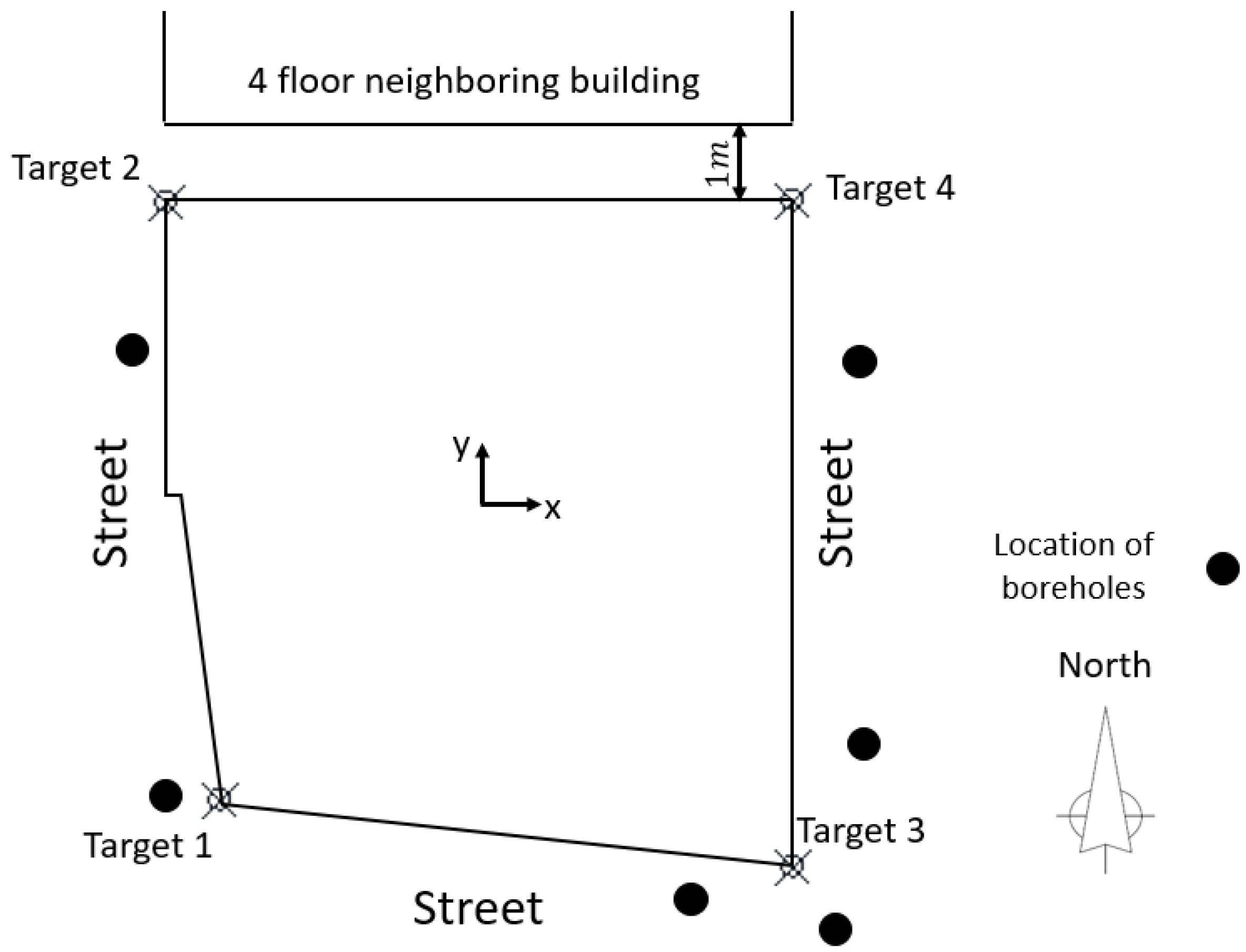
2. The tower is required to support an expected total load of approximately 49,664 kN, not including the weight of the rafts. Construction of the building began in February 2019 and finished in February 2020. The building layout is shown in
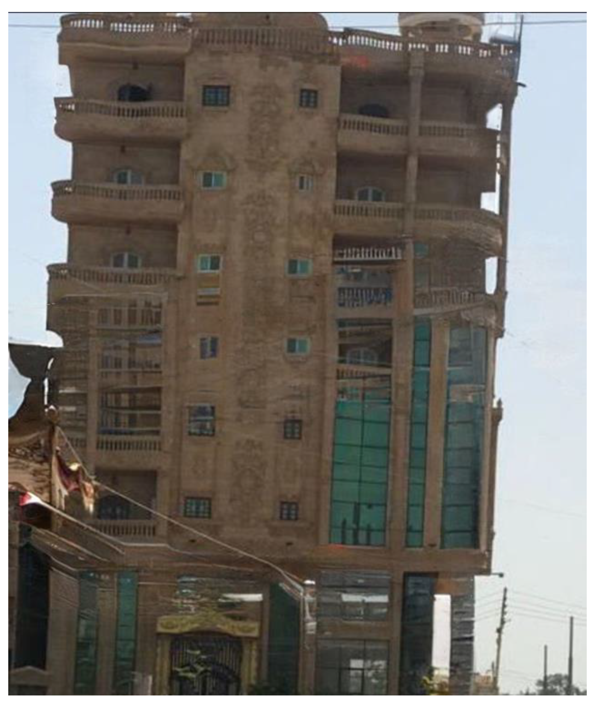
Figure 1, where it can be seen that an older building with four floors is located just 1 m to the north of the structure under investigation. In October 2020, after completion of the flooring and finishing work, it was observed that the tower was leaning toward the southeast.
Figure 2 presents a photograph of the tilted building from the southern side. When tilting was first observed, the only floors with live loads were the ground floor (with commercial use), the basement floor (used for car parking), and two higher floors.
2.1. Visual Inspection
In October 2020, a visual onsite inspection was carried out, and all available as-built structural drawings were scrutinized. The most important observations made during the visual inspection were as follows:
The structural elements had no visible cracks; the condition of the beams, columns, and slabs was excellent.
With the naked eye, an increasing horizontal distance could be observed between the tower under investigation and the adjacent building to the north; however, this distance could not be accurately measured.
In order to identify the primary factors contributing to the tilting of the building, preparations were made to carry out a soil investigation program.
2.2. Soil Conditions
In October 2020, a site investigation program was implemented to examine the soil stratification. The program involved drilling six boreholes around the tower, one to two meters from the tower edges at the locations depicted in
Figure 1, with a spacing of not more than 15 m, one 30 m deep, two 20 m deep, and three 15 m deep. A standard penetration test was carried out whenever granular soils were encountered. The SPT N shown in
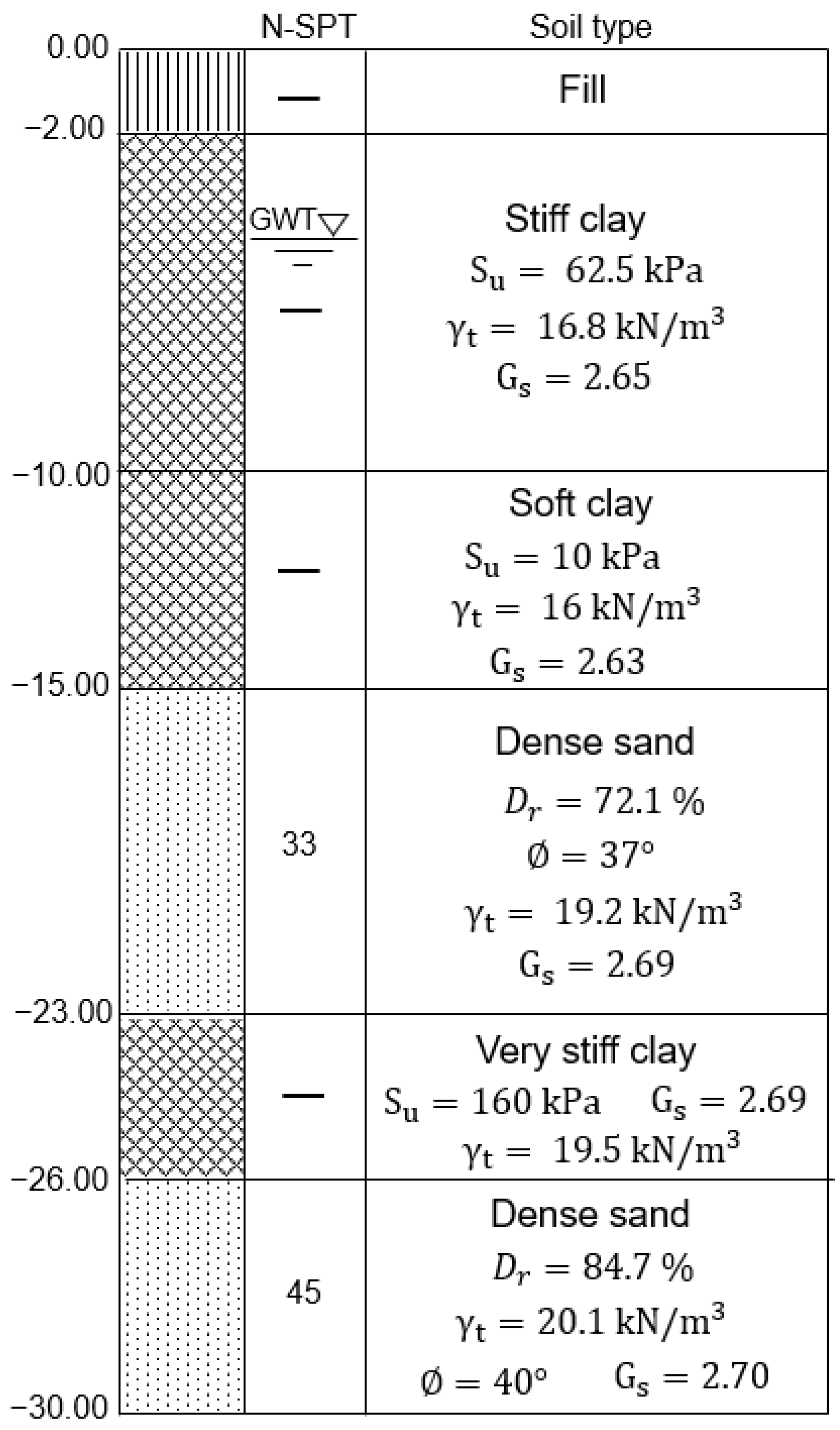
Figure 3 was taken as the average of the results recorded for the 6 boreholes. For cohesive layers, a Shelby tube sampler was utilized to collect undisturbed samples, which were then tested with a pocket penetrometer and unconfined compression tests. The site soil profile, depicted schematically in
Figure 3, consists primarily of: (1) fill from the ground surface to a depth of 2 m, (2) a layer of stiff clay from a depth of 2 m to 10 m, (3) a layer of soft clay from a depth of 10 m to 15 m, (4) a layer of dense sand from a depth of 15 m to 23 m, (5) a layer of very stiff clay from a depth of 23 m to 26 m, and (6) a layer of dense sand from a depth of 26 m to 30 m. The groundwater table was recorded at about 3.5 m below the ground surface, 24 h after drilling the boreholes. The total depth of the soft clay layer was observed to increase by up to 6 m toward the southeast corner of the site. In accordance with the soil conditions beneath the bottom of the raft (located 2.6 m below the ground surface), the soil was expected to have an allowable bearing capacity of 70 kPa. It is important to note that in early 2019, as per the recommendations of a geotechnical consultant, the plan was to construct the building on a piled raft. Despite this, the building was eventually built on a surface raft, and the consultant’s recommendations were disregarded.
2.3. Monitoring Survey
In May 2021, a comprehensive monitoring survey was carried out to determine how far the tower had moved. The process involved periodic checks of specific locations on the building, particularly the four corners at the top of the building, 27.8 m above the foundation level. Determining the lateral displacement of the tower over time became essential after it was observed that the building was starting to tilt at an alarming rate. Accelerating rates of displacement could have eliminated any possibility of foundation repair, forcing the project team to dismantle the tower. Aside from the expense involved, lives and property could have been endangered if the building had moved too far from its original position.
Thus, four monitoring targets were attached to the tower to aid observations. As shown in
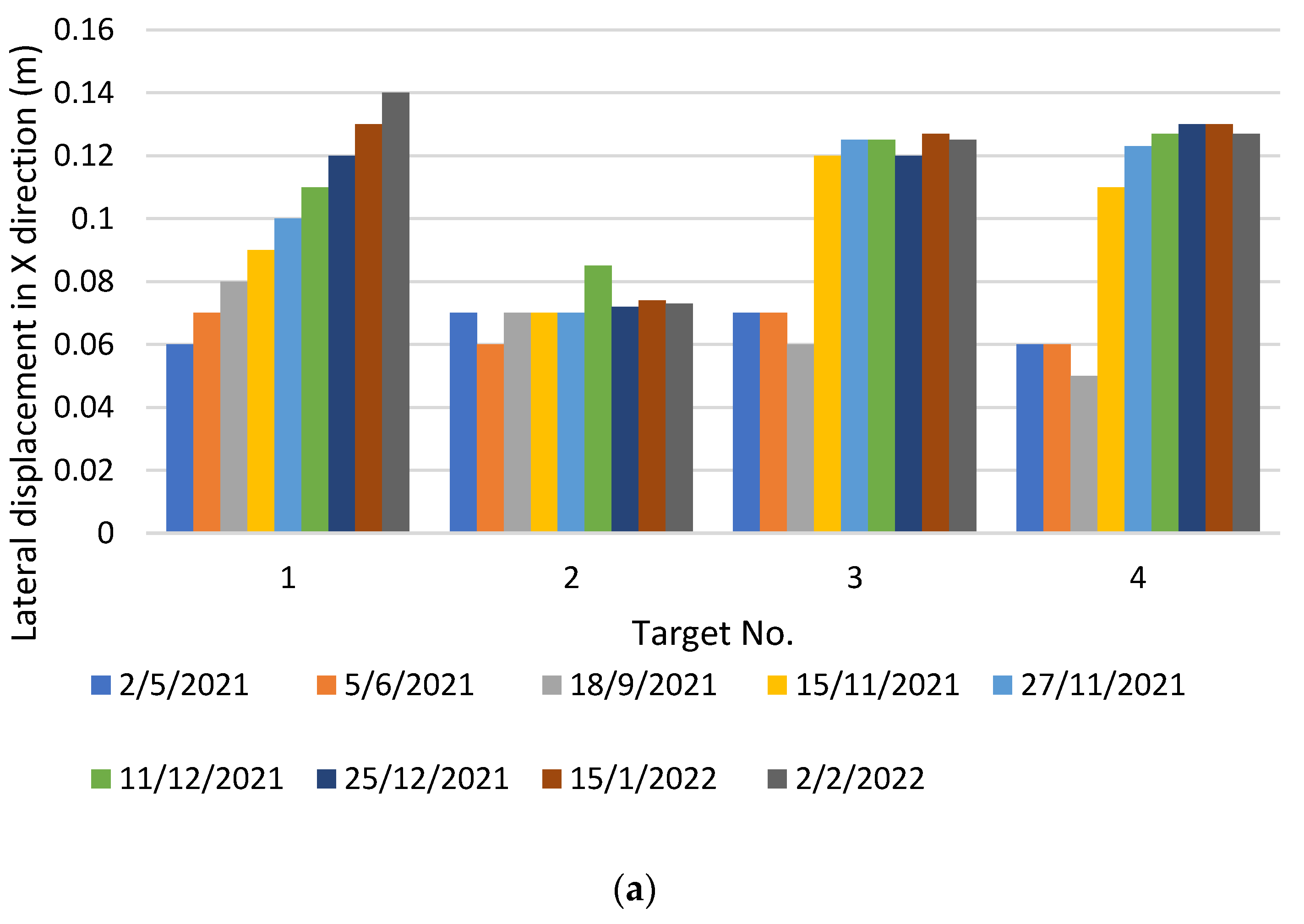
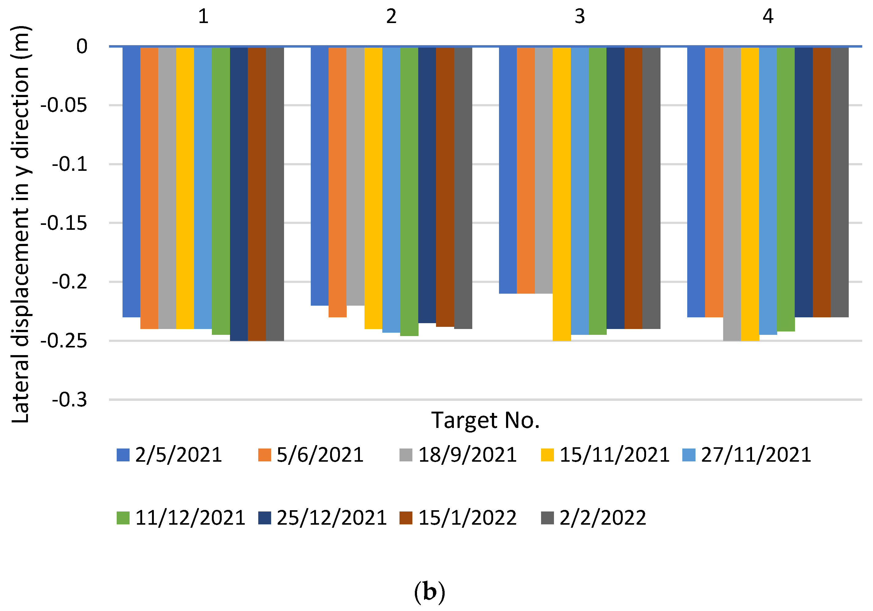
Figure 1, targets 1, 2, 3, and 4 were positioned at the top of the tower 27.8 m above the foundation level, at the southwest, northwest, southeast, and northeast corners, respectively. The monitoring survey observation results are presented in
Figure 4, where positive values of
x indicate displacement toward the east, and negative values of
y indicate displacement toward the south (see
Figure 1). In
Figure 4, it can be seen that the building was tilting farther toward the southeast corner until the installation of the repair system was implemented from 7 December 2021 to 1 February 2022. The monitoring survey indicated that the underpinning process itself initially induced some settlement. This could be attributable primarily to the micropile installation technique, which involved soil excavation, leading to stress relief. A similar observation was reported by Lopes et al. [
22]. Beginning on 25 December 2021, a noticeable reduction in the rate of displacement was observed, demonstrating the success of the repair system.
As shown in
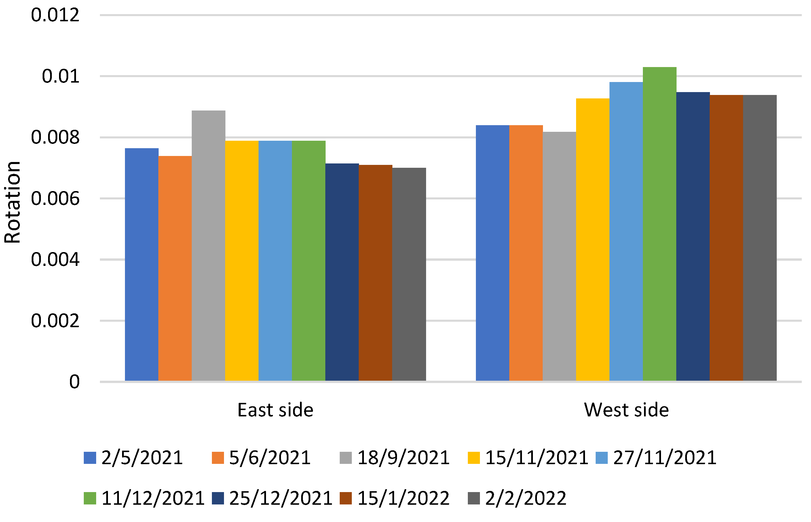
Figure 4, immediately prior to the micropiling process, on 27 November 2021, the building was tilted 24.5 cm toward the south and 12.5 cm toward the east. This corresponded to inclination ratios of around 1H:113V toward the south and 1H:222V toward the east. Moreover, rotations of the east and west sides of the raft were monitored over time. These rotations, calculated by using Equations (1) and (2), are presented in
Figure 5.
where
= settlement of the southeast corner,
= settlement of the northeast corner,
= settlement of the southwest corner,
= settlement of the northwest corner,
= distance between the southeast and northeast corners, and
= distance between the southwest and northwest corners.
3. Retrofitting the Foundation System
3.1. Preliminary Analysis
Despite the recommendation of a geotechnical consultant to use deep foundations, the tower was originally constructed with a foundation consisting of a raft with an area of 389 m2 positioned 2.6 m below the ground surface. Without considering the tilt, a 3D finite element model of the building was developed by using a commercially available software package (ETABS). Based on this structural model, the total load on the tower was estimated to be 49,664 kN, taking into account the live load, dead load, and floor coverings. It was found that there was a critical eccentricity of at least −40 cm in the y-direction between the centroid of the total tower loads and the centroid of the foundations. This eccentricity, in conjunction with the weak soil conditions, was presumed to be the primary factor leading to the tilt observed in the building.
By taking the building tilt into consideration, calculations showed that the maximum net contact soil stress was 151.7 kPa and occurred at the southeast corner; while the minimum net contact soil stress of 123.8 kPa was found at the northwest corner of the building. In addition, the contact soil stress resulting from the own weight of the raft and the live load on the basement floor was estimated to be 38.5 kPa. Hence, the total contact soil stress at the southeast and northwest corners was 190.2 kPa and 162.3 kPa, respectively. Of course, these values greatly exceeded the allowable soil bearing capacity which was 70 kPa. Given the adequate headroom of the basement floor and the weak soil layers beneath the existing raft, micropiling the raft seemed to be the most appropriate repair technique, especially since it would cause relatively little soil vibration or disturbance to existing buildings.
3.2. Proposed Micropiling System
To meet the repair objectives, it was determined that it would be sufficient to use a total of 111 micropiles measuring 20 cm in diameter and 17.6 m in length, with an allowable geotechnical capacity of 300 kN.
3.2.1. Micropile Length and Design Capacity
Micropile design can be regarded as comprising two primary aspects: structural design and geotechnical design. In terms of structural design, because the reinforcement ratio can exceed 15% of the micropile cross-sectional area [
24,
25], the type of steel reinforcement utilized is the primary factor governing the structural compression capacity. In the case under discussion, the reinforcement that was accessible was high-tensile steel tubing with an inner/outer diameter of 76/89 mm (5.4% of the area cross-section) and a yield stress of 3600
. A structural capacity of 523 kN was estimated by using the following relationship suggested by FHWA [
4]:
where
= the allowable micropile compression capacity,
= the unconfined compressive strength of the grout,
= the cross-sectional area of the grout,
= the yield stress of steel, and
= the cross-sectional area of the steel casing.
With regard to the geotechnical design, the two primary governing factors are the grouting technique and the bond length embedded in the bearing layer. There are four distinct types of micropiles [
4], classified according to the grouting technique used: Types A, B, C, and D. Type A: the grout is concreted without any injection pressure. Type B: injection pressure is used in pouring the grout into the hole and typically ranges from 0.5 to 1 MPa. Type C: the grout is poured first under the gravity head. Then, after the hardening of the poured grout, additional grout is poured using a sleeved pipe at a pressure of at least 1 MPa. Type D: similar to Type C, but a packer can be used at specific depths inside the sleeved pipe. In the case under consideration, Type B micropiles were adopted, where grout was injected into the holes at a pressure of 0.5 MPa. Micropiles installed with pressurized grout have the advantage of densifying the coarse-grained soil around them [
7,
10]. The FHWA advises that for Type B micropiles in granular soils, the ultimate bond strength between the grout and the ground should be between 1.2 and 3.6
. Based on an ultimate bond strength of 2.0 kg/
, a factor of safety of 2.0, and a bond length of 5.0 m embedded in the sand, a geotechnical capacity of 300 kN was estimated by applying the formula proposed by FHWA [
4]:
where
= the allowable micropile compression capacity,
= the grout-to-ground ultimate bond strength; F.S. = the factor of safety (2 to 3),
= the diameter of the drill hole; and
= the bond length.
3.2.2. Number and Arrangement of Micropiles
The present authors drew on their practical and theoretical experience to determine the number and location of micropiles, in order to develop the most effective design in terms of safety and cost. As discussed below, by applying three different design approaches, they provided the tower owner with a choice of three different micropile configurations. In each of the designs, the micropiles were distributed with a spacing of at least 3.75
d (where
d is the micropile diameter), and the micropile locations were concentrated below loaded areas to ensure the maximum benefit with regard to settlement reduction. No group reduction factor was applied in the calculations since applying a reduction factor is unnecessary if pressure-grouted micropiles with a diameter of 20 cm and a minimum spacing of 0.75 m are used [
4].
First Approach
This approach is based primarily on the premise that the micropiles must bear the percentage of the vertical load that exceeds the allowable bearing capacity of the soil. A similar approach has been reported by Han and Ye [
5]. The major steps involved in this approach were as follows:
Taking into consideration that the allowable bearing capacity of the soil () was 70 kPa, the micropiling system was designed to resist any additional stresses.
In the project, the total contact stress at the position of the center of each individual column (
) was determined by the following equation:
where
= total contact stress,
= the net contact stress due to column loads,
= own weight of the raft,
= live load on the raft,
= surface area of the raft.
Of this total contact stress, the stress to be borne by the micropiles used for underpinning (
) was the part exceeding the allowable bearing capacity of the soil. This was calculated as follows:
where
= the stress carried by the micropiles, and
= the allowable bearing capacity of the soil.
The percentage of the column loads carried by the micropiles (
) was calculated by using the equation:
From the percentage and the actual column loads, and taking into account the micropile capacity, the number of micropiles required to underpin the columns could be estimated.
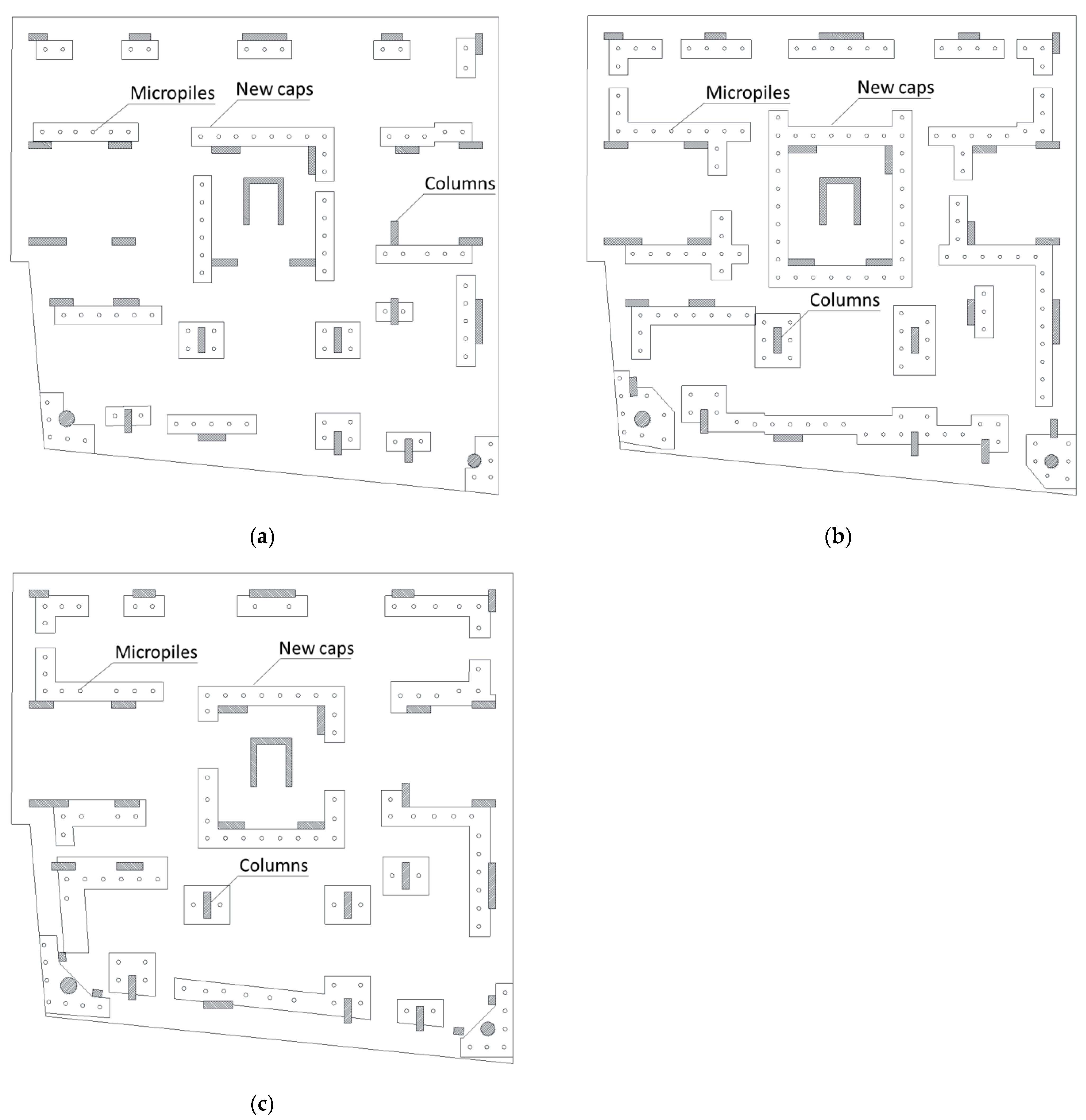
The total number of micropiles determined by this approach was 91, as illustrated in
Figure 6a. Of the three configurations proposed, this approach estimated the lowest number of micropiles.
Second Approach
This approach is considered to be the most conservative. It depends mainly on the principle of a floating foundation, where the foundation is placed at a depth below ground level such that the weight of the soil excavated to position the foundation is equal to the weight of the structure that is to be built. Hence, in this approach, the micropiles must bear the percentage of the vertical load that exceeds the weight of the excavated soil. The major steps involved in this approach were as follows:
Taking into consideration that a structure that causes stresses equivalent to the weight of the excavated soil ( should result in zero settlement, the micropiling system was designed to resist any additional stresses.
In the project, the total contact stress under the centers of the columns () was determined by using Equation (5).
Of this total contact stress, the stress to be borne by the micropiles used for underpinning (
) was the part exceeding the weight of the excavated soil. This was calculated as:
where
= the stress carried by the micropiles, and
= the weight of the excavated soil.
The percentage of the column loads carried by the micropiles () was calculated by using Equation (7).
From the percentage and the actual column loads, and taking into account the micropile capacity, the number of micropiles required to underpin the columns could be estimated.
The total number of micropiles determined by this approach was 164, as illustrated in
Figure 6b. Of the three configurations proposed, this approach estimated the greatest number of micropiles.
Third Approach
This approach primarily depends on modeling the tilted tower and its foundation system by using a commercially available software package such as ETABS. It is worth noting that ETABS is used a lot within the engineering practice in Egypt, but it is recommended to use a geotechnical design software to consider the soil-structure interaction properly. The major steps involved in this approach were as follows:
It is worth noting that the modulus of subgrade reaction is a relationship between soil pressure and deflection. Using the above-mentioned equation is for simplification. may be estimated by using more advanced ways.
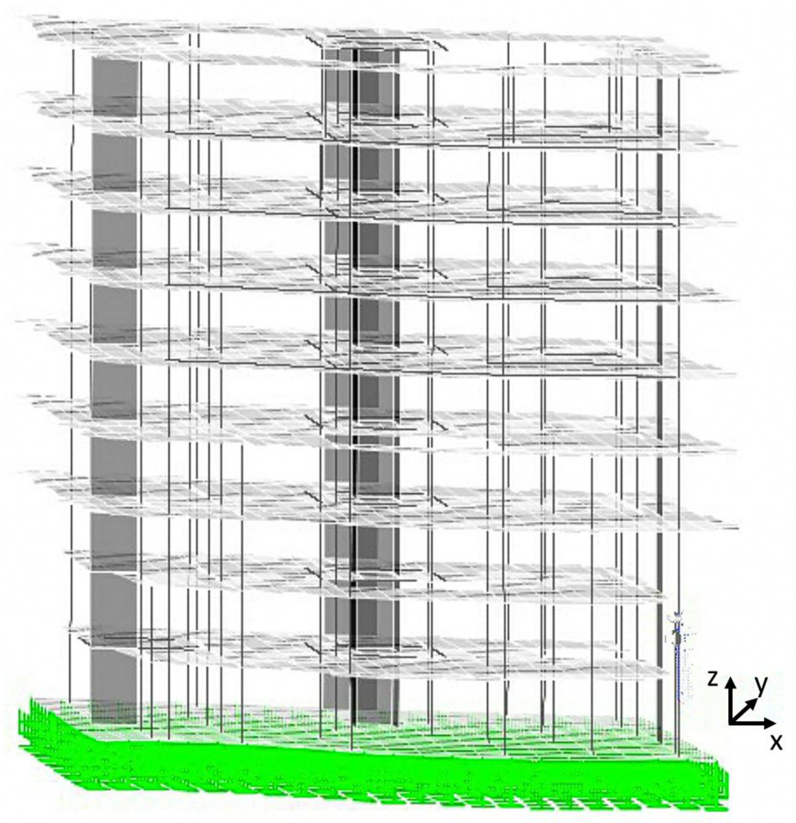
- 3.
In the model, the soil modulus of subgrade reaction was assigned. Moreover, a ground movement was input to represent the actual tilting of the building, as illustrated in
Figure 7.
- 4.
The micropile stiffness was estimated by using the results of a micropile load test, described subsequently.
- 5.
Through an iterative process, different numbers and arrangements of micropiles were examined to find the configuration offering the best soil stress distribution and micropile loading, taking into account that the maximum allowable soil stress was 70 kPa and the micropile geotechnical capacity was estimated as 300 kN.
The total number of micropiles determined by this approach was 111, as illustrated in
Figure 6c. Of the three configurations proposed, this was the one selected for the rehabilitation process. It is worth noting that the three discussed configurations considered not imposing any architectural modifications in the basement floor, as requested by the owner.
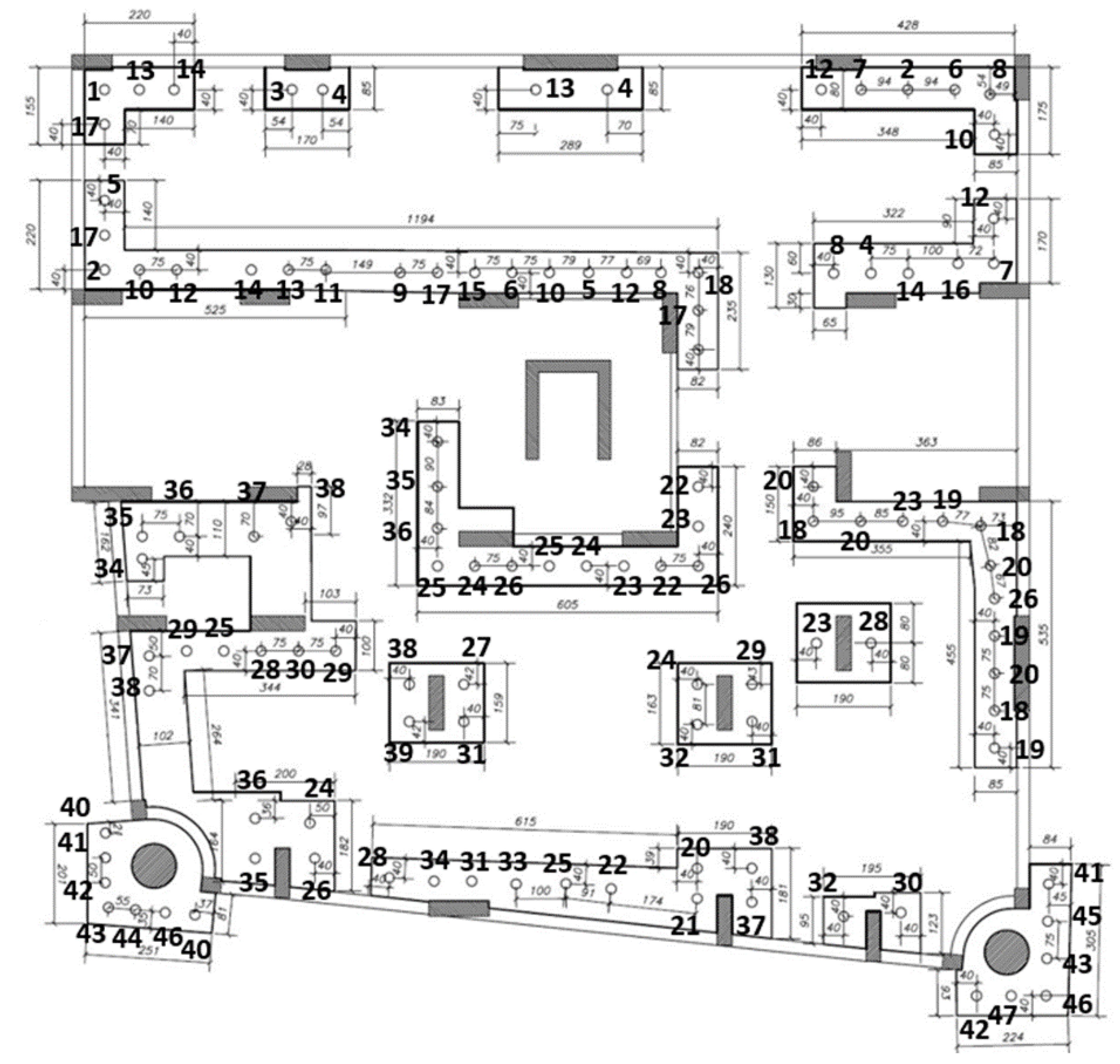
3.3. Micropile Installation Process
Figure 8 presents the as-built layout of the existing raft, following underpinning with micropiles. A hollow stem auger was used to drill the hole for each micropile. Throughout the process, bentonite slurry was used as the drilling fluid. Once the target depth was reached, grout was injected through the hollow stem at a pressure of 0.5 MPa, completely replacing the drilling fluid. After the removal of the hollow stem, a steel tube, coated against corrosion and with an inner/outer diameter of 76/89 mm, was inserted. Finally, a steel head plate measuring 25 cm × 25 cm was attached to each micropile.
To ensure minimal soil disturbance and to reduce undesirable settlement caused by soil removal during installation of the bored micropiles, no more than four micropiles were installed each day, for a total of 47 days, from 7 December 2021 to 1 February 2022, starting with the raft northern half followed by the southern half. Moreover, micropiles installed on the same day were not adjacent but were located at a distance from one another. The minimum spacing ever recorded for the micropiles installed per one day was 4 to 5 m.
Table 1 shows the micropile installation dates for each of the 47 days when micropiles were installed. In
Figure 8, the small-sized numbers refer to the micropiles spacing and dimensions of new pile caps in cm, whereas the large-sized numbers refer to the installation day (from 1 to 47) indicated beside each micropile.
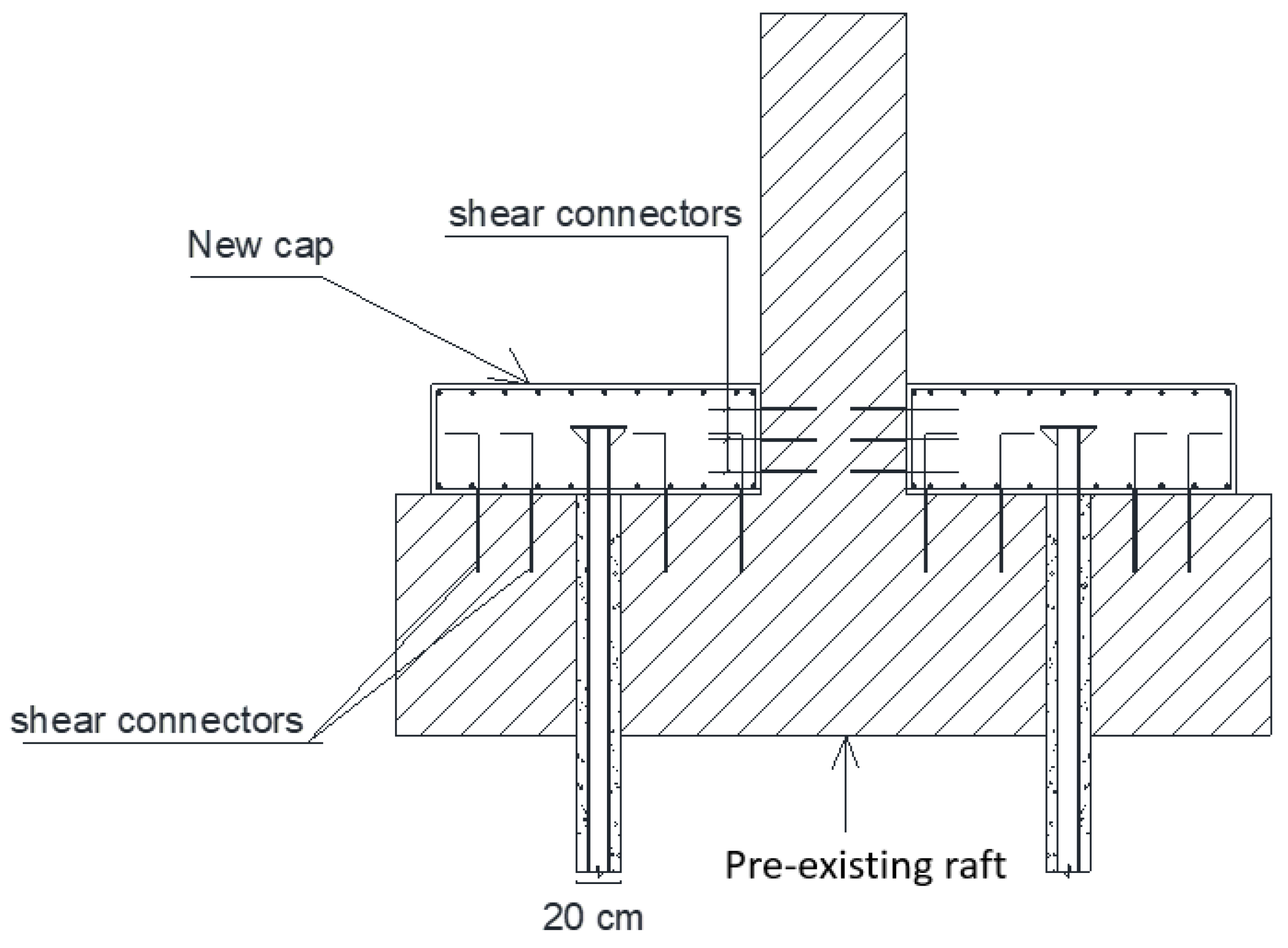
Following completion of the installation of micropiles around a particular column, a reinforced concrete cap with a thickness of 400 mm was used to join the micropiles to the column and to the pre-existing raft. Vertical and horizontal shear connectors were utilized for this purpose.
Figure 9 illustrates a sample cross-section of the micropiled raft, showing the pre-existing raft, a column, two micropiles 20 cm in diameter, a new reinforced concrete cap, and shear connectors.
3.4. Verification of Individual Micropile Capacity
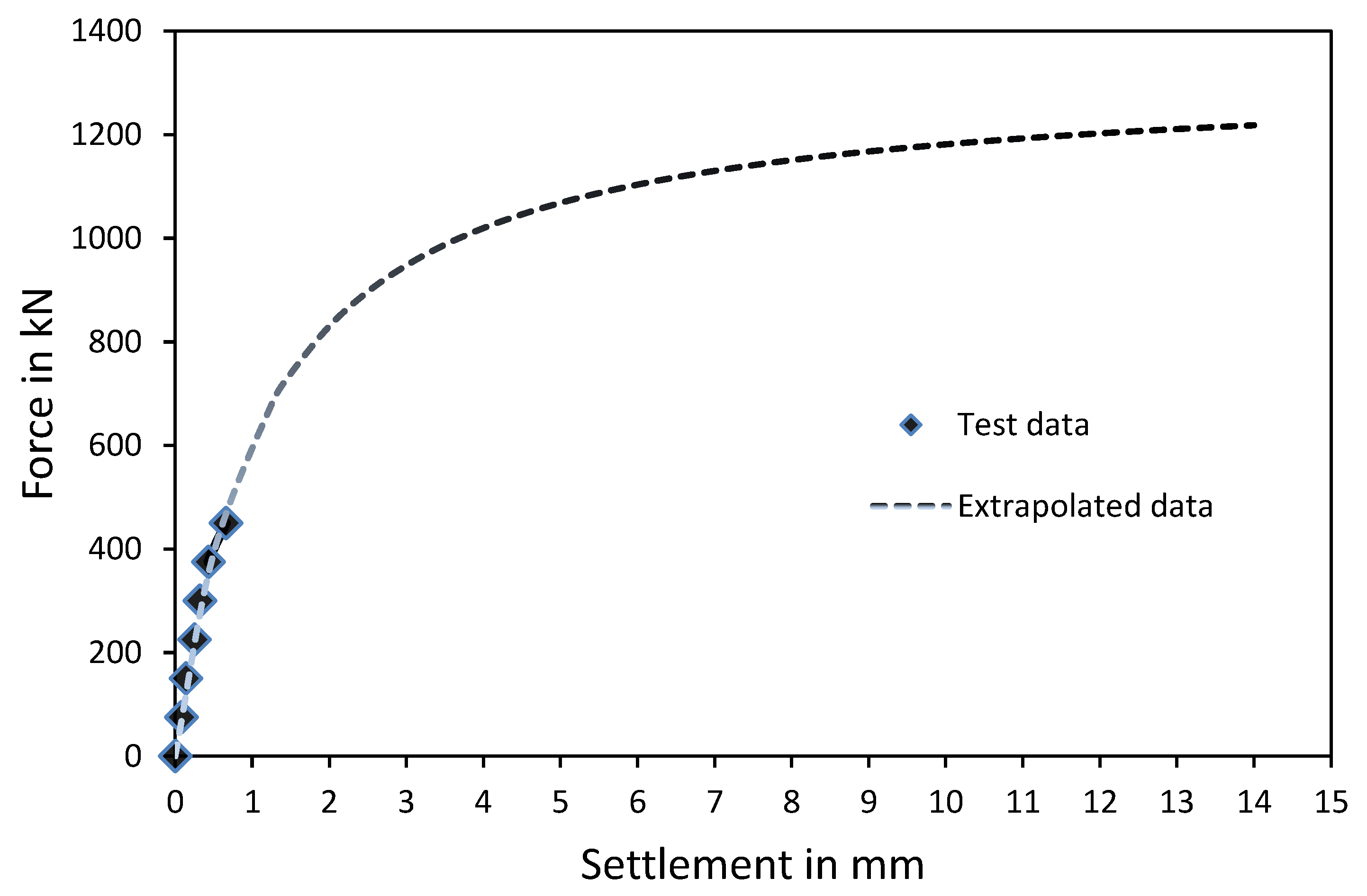
In order to confirm the actual micropile geotechnical capacity, a vertical static load test was conducted on one of the bearing micropiles. A test load of 450 kN was used, which caused a maximum settlement of 0.66 mm, as shown in
Figure 10. Based on the authors’ knowledge of micropile load tests, the behavior of the tested micropile was determined to be excellent. This could be attributed primarily to the grouting technique used for Type B micropiles, where grout is injected under high pressure, resulting in associated ground improvement. It should also be noted that the micropile used for testing was located in the northern half of the building, where the soil profile may be better than that observed in the initial investigation of the soil around the building. An analysis of the test results confirmed this advantageous micropile behavior and estimated the allowable static load to be 562 kN. This represented the average value obtained from the modified Chin and Brinch Hansen methods that are usually used to analyze pile load tests [
27].


