Article

Experimental Study on the Mechanical Properties of Composite Damped Hinge Bearings

1
School of Civil Engineering, Guangzhou University, Guangzhou 510006, China
2
Guangdong Architectural Design & Research Institute Co., Ltd., Guangzhou 510010, China
*
Author to whom correspondence should be addressed.
Buildings 2023, 13(2), 383; https://doi.org/10.3390/buildings13020383
Submission received: 15 December 2022 / Revised: 22 January 2023 / Accepted: 27 January 2023 / Published: 31 January 2023
(This article belongs to the Special Issue Next-Generation Intelligent and Resilient Structures)

Abstract

:
To resolve the problem of the super-long steel structures producing high-temperature stress on the lower concrete roof column section and improve the structure’s seismic performance, in this paper, we introduce a type of composite damped hinge bearing (CDHB). Firstly, this paper introduces the detailed construction of the CDHB and elaborates on its working principle. The mechanical properties of a CDHB have been tested, including the monotonic loading test on the whole bearing and the reciprocal loading test on the built-in dampers. The CDHB’s working performance, rotation performance, and energy consumption performance under tensile and compressive forces are also discussed in this paper. The study results show that: (1) Generally, the vertical deformation of the CDHB increases linearly with the increase of compressive and tensile forces, while it decreases with the increase of initial displacement. (2) Under vertical loading, the CDHB can reach a turning angle of 0.6 rad. The bearing is more likely to rotate with the increase in initial displacement. (3) The ultimate displacement, maximum damping force, damping constant, and damping coefficient of the built-in dampers are all stable.

1. Introduction

In large stadiums and airport terminal buildings, in order to obtain a larger indoor space, a constructional system consisting of an upper steel structure section and a lower concrete section is generally applied [1,2]. In this system, the top of the roof column on the lower concrete section supports the upper steel structure. In order to reduce the bending moment at the top of the roof column, a hinge bearing is usually set at the column top to form an articulation with the upper steel structure, to release the column top bending moment and to reduce the amount required of the column bottom reinforcement [3,4,5].
A universal spherical hinge bearing (e.g., seismic steel ball bearing [6,7] or seismic spherical steel bearing [8,9]) is usually applied to connect the steel and the concrete structures. The universal spherical hinge bearing can limit the three-dimensional transversal displacement and release some angle constraints, but it is only applicable to structures with a relatively narrow span. However, in such large projects as stadiums and airport terminal buildings, the steel-structure roofs have long continuous lengths, which often produce excessive temperature effects at the roof-column top at the far end. The horizontal shear force caused by the temperature effect is significantly greater than the forces caused by other working conditions, making the roof column at the far end bear unreasonable amounts of force. Studies on spherical bearings and other types of bearings are focused on their structural and detailed design, mechanical analysis, and experimental study. For example, Xu et al. proposed a multidimensional high-damping earthquake isolation device (MHEID) for a long-span reticulate structure [4]. A composite spherical bearing (CSB) composed of carbon–phenolic composite race and steel ball was developed by Kim et al. [10], and the endurance and performance of CSB were investigated [11]. Fenz and Constantinou conducted an experimental program to examine the force–displacement behavior of a class of multi-spherical sliding bearings [12].
In order to solve the problem of a super-long structure producing excessive temperature-induced internal forces on the frame column at the far end, the current solution is to set a vibration isolation bearing [13,14,15,16] and a friction pendulum bearing [17,18,19,20,21] at the roof-column top to connect the top with the steel structure. However, the tensile capacities of these two bearings are poor. Usually, they cannot meet the tensile performance requirements on the roof bearings of large-span steel structures, thereby making their application quite limited. Some scholars proposed using a sliding bearing to connect the concrete column top with the steel structure [22,23,24,25]. This kind of connection can release the temperature stress, but meanwhile, it reduces the structural lateral stiffness, which is not conducive to the whole seismic performance. Adding metallic dampers (e.g., the triangular-plate added damping and stiffness (i.e., TADAS)) [26] or added damping and stiffness (i.e., ADAS) [27]) inside the structure can adjust the stiffness and damping of the structure. Since the metallic damper cannot be reset after deformation, it is not suitable for controlling the temperature-induced internal forces of the structure. A tuned mass damper (i.e., TMD) is designed so that its natural frequency is close to the control frequency of the main structure [28]. Once vibration occurs, due to the effect of inertia, the TMD will exert an inertial force opposite to the vibration direction on the structure, thereby reducing the vibration of the main structure. However, the weight of the TMD mass block needs to reach a certain proportion of the structure to function, and a certain amount of space is required for installation, so it is rarely used in building structures. Therefore, more effective isolation bearings should be developed to resolve the problem of the super-long steel structure producing high-tensile stress on the lower concrete roof column section.
Based on this, in this paper, we introduce the composite damped hinge bearing (CDHB) to resolve the problem of a super-long steel structure producing high-temperature stress on the roof column of the lower concrete section. This paper first provides the CDHB’s structure scheme and elaborates on its working principle. Then it illustrates the CDHB we have built and the built-in dampers (we built ten damper units). Furthermore, the paper explains the tension and compression tests and the rotation test we have carried out on the CDHB. It also explains the axial tension and energy consumption performance tests on the built-in dampers of the CDHB.

2. Configuration and Working Principle of the CDHB

2.1. Configuration

The CDHB consists of an upper cover plate, middle force transmission bracket, damper connection plate, built-in dampers, lower spherical hinge sliding plate, lower spherical hinge support, and lower plane sliding plate. A modified ultra-high molecular weight polytetrafluoroethylene sliding plate is set between the upper cover plate and the middle force transmission bracket. The middle force transmission bracket is then connected with two built-in dampers set in the same direction, on both sides of the bracket through a connecting plate on each side. The piston rod of each built-in damper is close to the ear plate of the upper cover plate. Sliding plates are installed inside the CDHB. Specifically, the bracket bottom is connected with the bottom case through a spherical sliding plate, a spherical crown liner plate, and a sliding plate, as shown in Figure 1. The built-in dampers are separated from the upper cover plate and the bottom case, which has the advantage of easy replacement.

2.2. Working Principle

Under vertical pressure, the CDHB transmits successively more force to the bottom case through the upper cover plate, upper sliding plate, middle force transmission bracket, and lower spherical support unit. Because the gaps between its components are tiny, the CDHB has good compression properties. Moreover, the force transmission path of the vertical tension is the same as the path of the vertical pressure, with an opposite force transmission direction. When the clips between the upper cover plate and the middle force transmission bracket and the clips between the middle force transmission bracket and the upper section of the bottom case are fastened firmly, the CDHB will display good tension properties. Under horizontal loading, the CDHB’s upper cover plate will have a translational displacement in the plane, which deforms the built-in dampers axially, and makes the CDHB rotate around the bottom case, producing a rotation angle.
The CDHB combines the spherical hinge support and the sliding support with the dampers, giving full play to the advantages of individual units. A spherical hinge joint between the bottom case and the lower section of the middle force transmission bracket forms, allowing the bracket to rotate around the bottom case in spherical directions to meet the requirements on the rotation angles. Along the horizontal direction, the upper cover plate connected with the upper structure can slide to absorb the tensile and compressive deformation of the super-long structure under the temperature effect and eliminate the resulting internal temperature. Under horizontal seismic or wind loading, the built-in dampers will have hysteretic deformation along the radial direction, which can help dissipate energy and reduce the structural response.
The upper cover plate of CDHB is connected to the upper steel structure, and is connected to the lower support column. In normal operation, the steel structure roof drives the upper cover plate in the vertical direction of the built-in damper, and the middle force transmission bracket produces a sliding displacement. Along the direction of the built-in damper, the steel structure roof drives the upper cover plate to push and pull the built-in damper, thereby generating a damping force which acts on the damper connection plate. The damper connection plate is embedded with the middle force transmission bracket, and the damping force acts on the lower lane sliding plate, and finally acts on the lower support column.

3. Test Design

3.1. Specimen Design

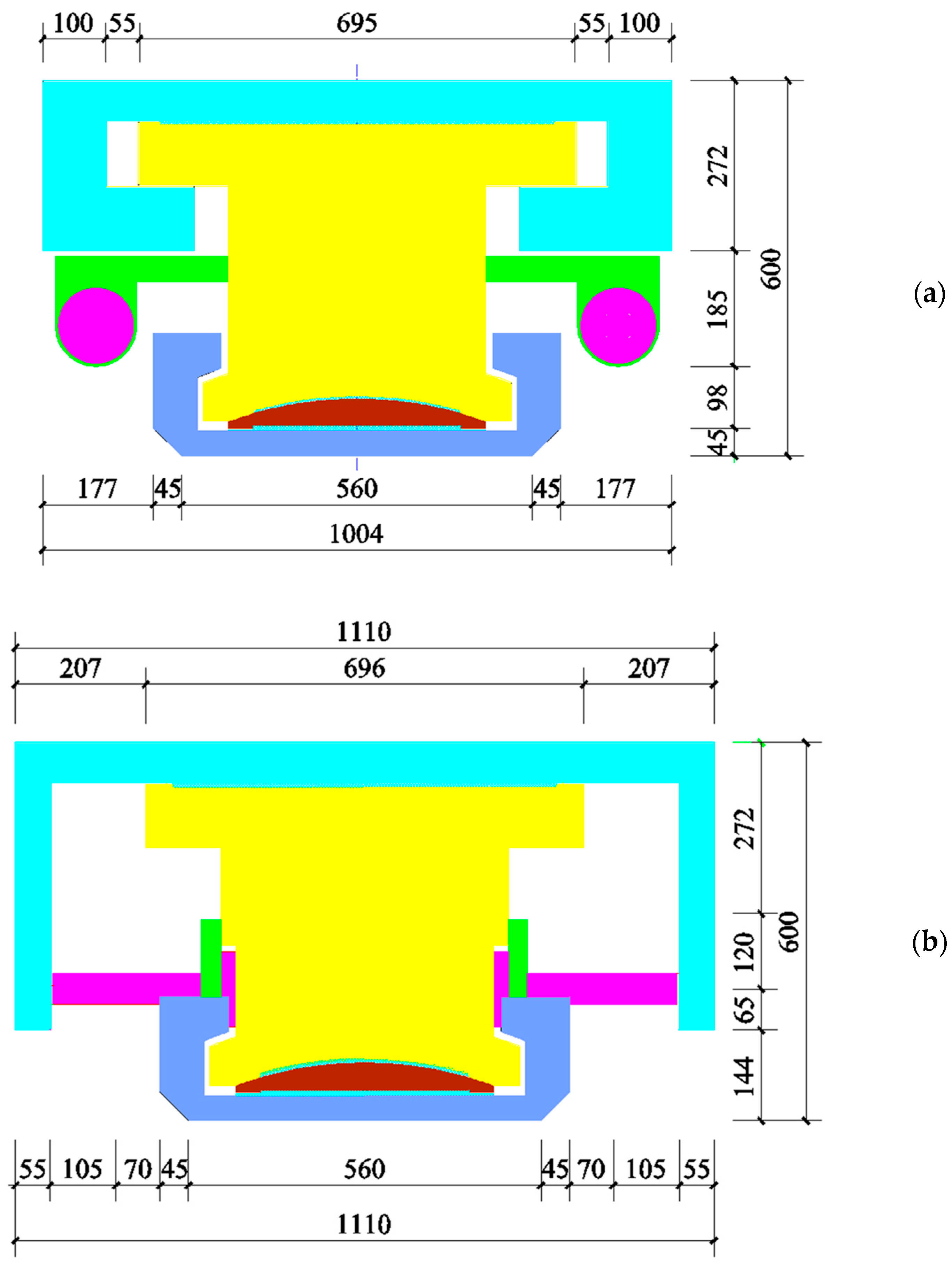
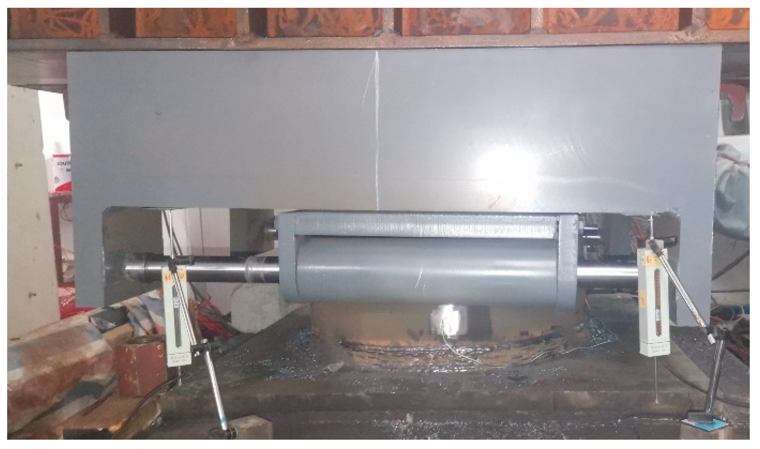
We fabricate one overall CDHB and ten sets of built-in dampers to study the mechanical properties of the CDHB. Table 1 and Table 2 show the mechanical properties of the specimens. Figure 2 shows the basic dimensions of the CDHB tested, Figure 3 shows the basic dimensions of the built-in dampers, and Figure 4 shows a picture of the whole testing unit. The steel used for making the CDHB is No. 25 steel made in China, with a yield strength of 275 MPa and an elastic modulus of 260 GPa.

3.2. Loading Device and Loading Scheme

3.2.1. Loading Device

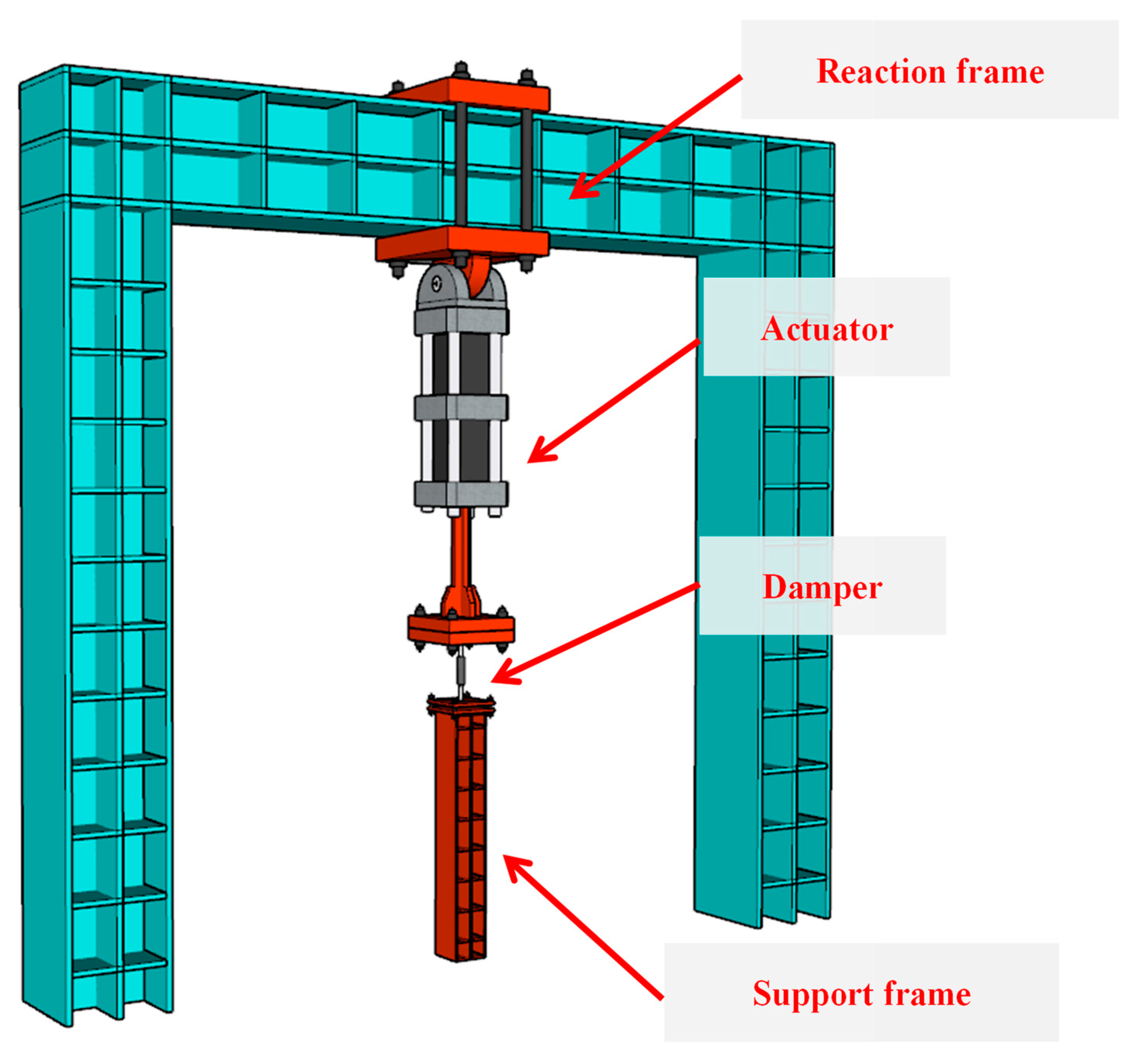
Figure 5 shows the loading scheme of the monotonic loading test of the whole CDHB. In the test, two vertical hydraulic jacks are used to provide a vertical compressive loading force of up to 10,000 KN, and another two vertical hydraulic jacks are used to provide a vertical tensile loading force of up to 4000 KN. Figure 6 shows the loading scheme of the reciprocating loading test of the built-in dampers. The MTS loading scheme is applied, with a maximum loading force of 500 KN and a maximum loading displacement of ±200 mm.

3.2.2. Loading Scheme

In this test, we mainly study the loading capacities of the CDHB under the action of compression, tension, and bending moment, with an initial displacement of 0, 25, and 50 mm, respectively. Table 3 shows the test conditions.
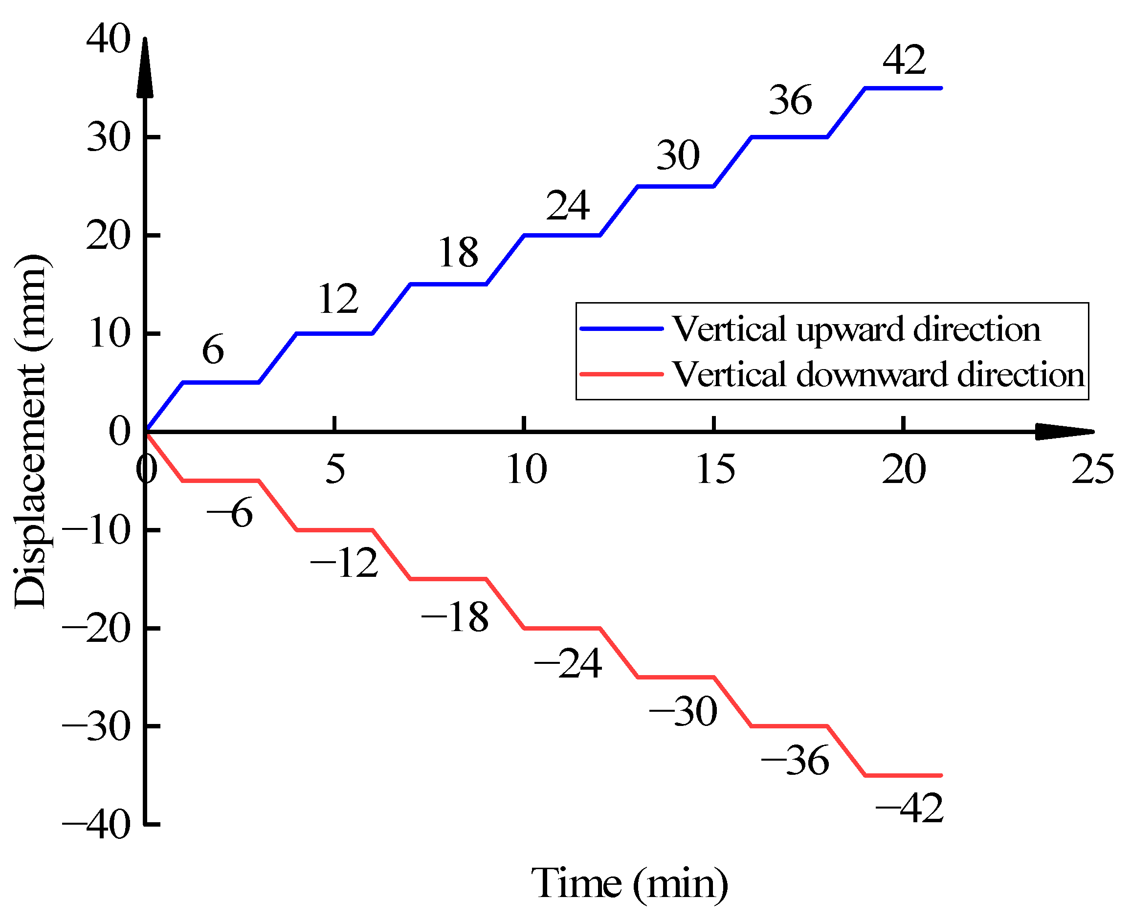
To study the bearing capacity of the CDHB under compression and tension, we have carried out the loading capacity test of the CDHB according to the spherical bearings for steel building structure (GB/T 32836-2016) [29]. When loading, take 10% of the maximum vertical loading of the test as a level difference and carry out the horizontal loading test with ten levels. Figure 7 shows the loading scheme of the CDHB’s vertical compression and tension deformation test.
To test the CDHB’s bearing capacity under the states of compression rotation and tension rotation, we have carried out the CDHB’s compression rotation and tension rotation loading capacity test. The loading process of the test is as follows: (1) Adjust the initial displacement to 0 mm and preload the CDHB. Slowly increase the vertical loading of the two groups of vertical hydraulic jacks simultaneously to the vertical design load of the CDHB and then keep the loading constant for 3 min. Unload the CDHB and stop for 3 min. Repeat the preloading test, as mentioned, three times. (2) Then start the loading test. Adjust the reading of the displacement meter to zero, increase the loading of the CDHB to its vertical design load and keep the loading constant there for 3 min. Read and record the corresponding vertical load reading of the displacement meter, and then adjust the reading to zero. Then, using the displacement control, carry out the pressure rotation angle or tension rotation angle test in six levels, with the change of vertical displacement in each level controlled at 5 mm. Adjust the oil pressure of the two groups of vertical hydraulic jacks, slowly increasing the oil pressure of the jack group on the left and slowly decreasing the oil pressure of the jack group on the right, to keep the average loading at the design load. When the reading change of the displacement meters on both sides reaches 5 mm, keep the loading constant for 3 min, and record the loading of the two groups of vertical jacks at that time, as well as the readings of the displacement meters. Once the maximum loading is reached, keep the loading constant there for 3 min and unload the CDHB. Take the product of pressure difference and the distance of the jacks as the load bending moment. During the test, the lower plane sliding plate in the CDHB is welded to the bottom steel section, and the bottom steel section is embedded in the ground. When tension is applied, the hydraulic jack above the CDHB loosens, and the hydraulic jack below tightens the upper cover plate to generate tension. Figure 8 shows the loading scheme of the pressure rotation angle and tension rotation angle test. Following the unloading of the vertical loads, apply a horizontal force to displace the CDHB horizontally by 25 mm and 50 mm, respectively. Then do the preloading and loading tests, as mentioned above, and record the loading of each jack group and the readings of the displacement meters.
We have performed the axial tensile and energy consumption performance tests to measure the built-in dampers’ mechanical properties. Both tests comply with the technical specification for seismic energy dissipation of buildings (JGJ297-2013) [30] and dampers for vibration energy dissipation of buildings (JG/T 209-2012) [31]. In the ultimate displacement test, we apply the experience record test method with the movement rate of the MTS loading system at controlled at 1 mm/s. Then, we record the ultimate displacement of the fore-and-aft motion. In the maximum damping force test, we use the sinusoidal excitation method and apply a sinusoidal force with displacement u = u0·sin(2πft) and displacement amplitude u0 = 125 mm, according to the sinusoidal law. The loading frequency f is 1 Hz. Following five successive testing cycles, we use the recorded maximum damping force corresponding to the third cycle as its measured value. Figure 9 shows the loading scheme. In the test of the damping constant and damping coefficient, we use the sinusoidal excitation method and apply a sinusoidal force with displacement u = ui·sin(2πft), and displacement amplitudes UI of 0.1 times, 0.2 times, 0.5 times, 0.7 times, 1.0 times, and 1.2 times of u0, respectively. A total of five test cycles have been carried out successively. During each cycle, we draw the damping force-displacement hysteresis curve. Furthermore, under each working condition, we calculate the damping constant and damping coefficient corresponding to the third cycle and use the results as their measured values. We also apply the same sinusoidal excitation method mentioned in the tests under different frequencies. According to the sinusoidal law, we apply a sinusoidal force with displacement u = u0 sin(2πft) and loading frequencies f of 1.0 times, 1.3 times, 1.6 times, 1.9 times, and 2.1 times of f1, respectively, to obtain the maximum damping force under different frequencies.

4. Test Results

4.1. Vertical Bearing Capacity Performance

Figure 10 shows the CDHB’s pressure-displacement curves under different initial horizontal displacements. From Figure 10, the pressure-displacement curves of the CDHB are linear under different initial displacements. When the initial displacement changes from 0 mm to 25 mm to 50 mm, the vertical compressive stiffness of the CDHB decreases accordingly, with the maximum vertical displacements of 1.99 mm, 1.77 mm, and 1.59 mm, respectively. It can be seen that within the design range of vertical pressure, the CDHB is basically in an elastic state, the vertical deformation increases linearly with the increase of pressure, and under the same vertical pressure, the CDHB’s vertical deformation decreases with the increase of initial displacement.
Figure 11 shows the picture of the compression test of the CDHB with the initial displacement of 0 mm. During the loading process, there is no noticeable sound, from which we can know that there is no gap between the components of the bearing when they are under pressure, and that the force transmission is direct.
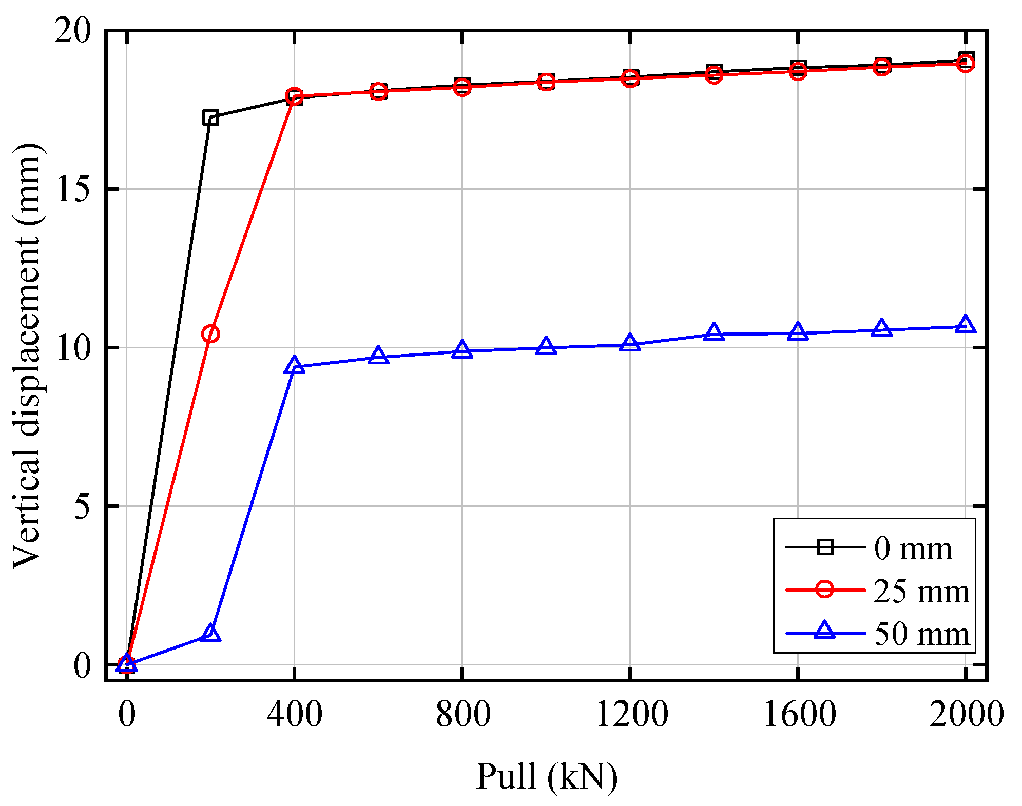
Figure 12 shows the CDHB’s tension-displacement curves under different initial horizontal displacements. Figure 12 also shows that the CDHB’s tension-displacement curves all present a double-fold line pattern. At the initial stage of tension application, the CDHB’s vertical displacement increases rapidly. Following the inflection point, the curves tend to flatten. The maximum vertical displacements of the CDHB is 19.07 mm, 18.96 mm, and 10.66 mm, respectively, under the initial horizontal displacement of 0 mm, 25 mm, and 50 mm. It shows that because of the gap between the middle force transmission bracket and the bottom case, the CDHB’s initial vertical displacement increases rapidly under the action of tension. When the initial horizontal displacement reaches 50 mm, that gap decreases, which makes the vertical displacement under this horizontal displacement more minor than the displacements under the other two conditions. When the CDHB’s cover plates attach closely to each other, the CDHB is basically in an elastic state, and its tensile stiffness under different initial displacements does not vary.
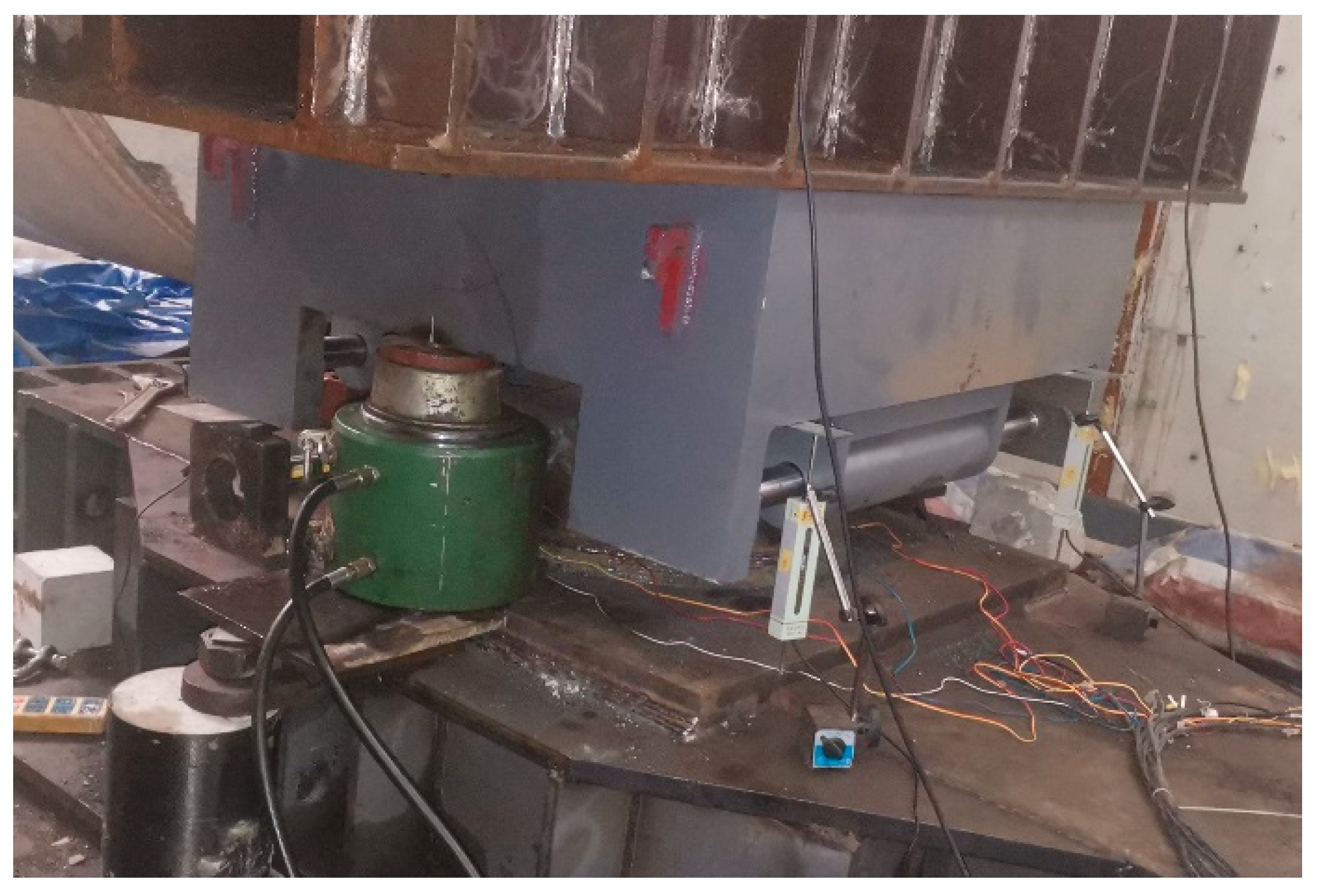
Figure 13 shows the picture of the CDHB’s tension test under an initial horizontal displacement of 0 mm. During the initial stage of the loading process, there is a sound of “ka” under different initial displacements. It shows that when the CDHB’s components are under a tensile force, the gap between the middle force transmission bracket and the bottom case is compressed first, and then each component starts to transmit that tensile force.

4.2. Rotation Performance

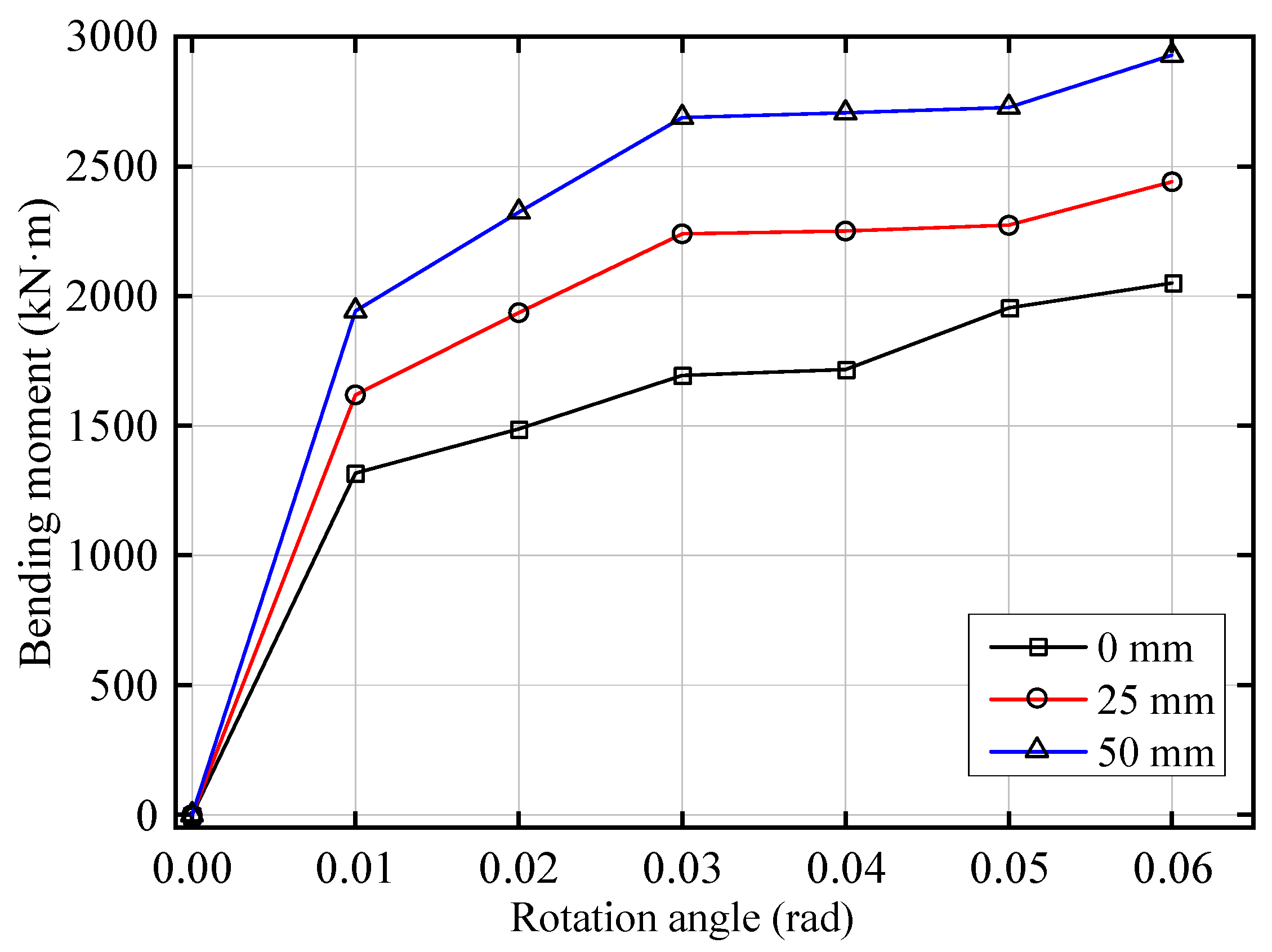
Figure 14 shows the CDHB’s rotation angle-bending moment curves under different horizontal displacements when the CDHB is under the action of vertical pressure. We can see that within the rotation angle range of 0 to 0.01 rad, the CDHB’s bending moment under each working condition increases rapidly with the increase of the rotation angle. Then, it increases linearly. The maximum rotation angle under each condition can reach 0.06 rad. Under the same rotation angle, the CDHB’s bending moment decreases when the initial horizontal displacement changes from 0 mm to 25 mm to 50 mm, with a maximum bending moment of 2850 kN·m, 2450 kN·m, and 2100 kN·m, respectively. We can see that the CDHB has a good rotation performance under pressure. With the increase of the initial horizontal displacement, the bearing tends to rotate more easily.
Figure 15 shows the picture of the CDHB’s compression rotation angle test under an initial displacement of 0 mm. During the loading process, there is no noticeable sound, which shows that after the compression force is applied to the CDHB, there is no gap between all CDHB’s components when it starts rotating, and the force transmission is direct.
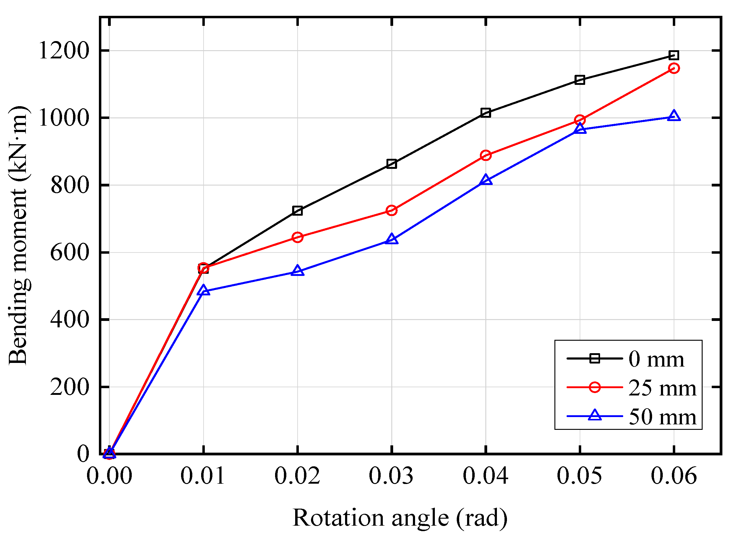
Figure 16 shows the rotation angle-bending moment curves under different initial horizontal displacements when the CDHB is under the action of vertical tension. Figure 16 also shows that under different initial horizontal displacements, the rotation angles can all reach 0.06 rad, and the rotation angle-bending moment curves are all linear. The CDHB’s bending moment decreases when the initial displacement changes from 0 mm to 25 mm to 50 mm, with the maximum bending moment of 1190 kN·m, 1150 kN·m, and 975 kN·m, respectively. It shows that under vertical tension, the CDHB has a good rotation performance. With the increase of the initial displacement, the CDHB tends to rotate more easily.
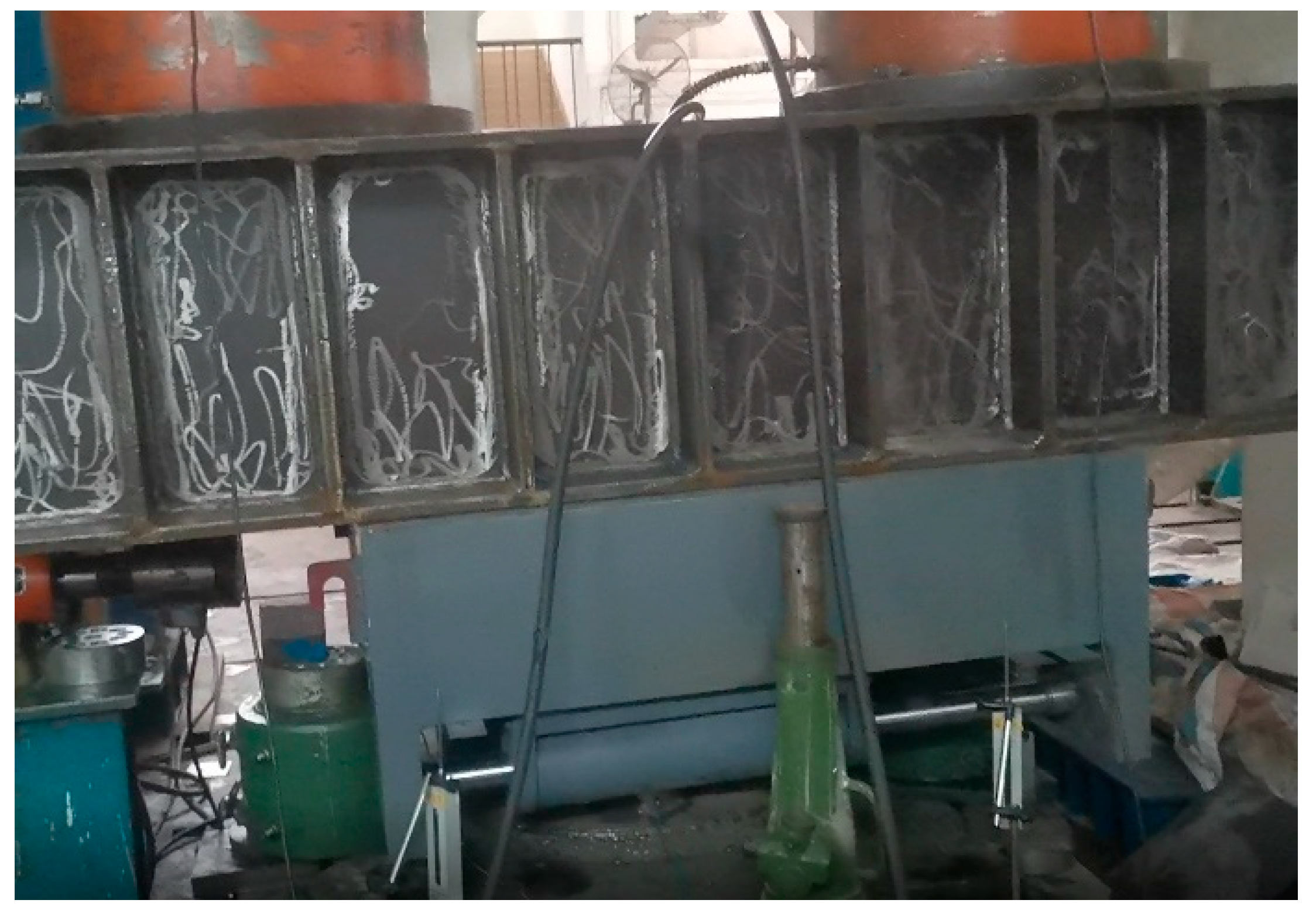
Figure 17 shows the picture of the CDHB’s tension rotation angle test under an initial displacement of 0 mm. During the loading process, there is no noticeable sound, which shows that when the CDHB is under tension, there is no gap between all components when the CDHB starts rotating and the force transmission is direct.

4.3. Mechanical Properties of the Built-In Dampers

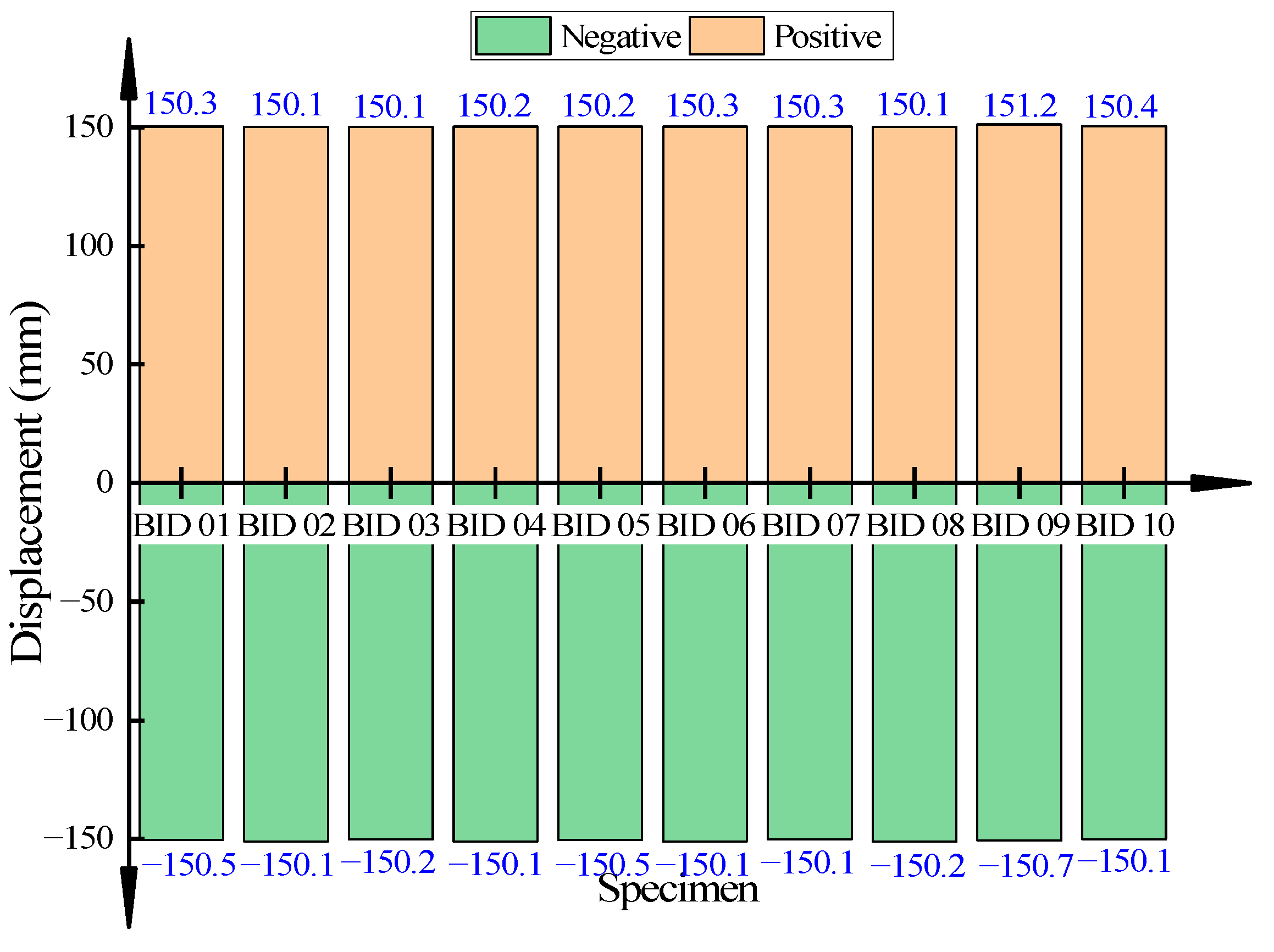
Figure 18 presents the test results of the ultimate displacement of the built-in dampers (from BID 01 to BID 10). From Figure 18, we can see that the measured positive mean of the built-in dampers’ displacement is +150.31 mm, while the measured negative mean is −150.66 mm. Both are more than 1.2 times the design stroke (±150 mm). It shows that when the viscous damper is scaled down by a large proportion, its ultimate displacement is quite stable, which can meet the requirement of the bearing sliding 100 mm in one direction.
The ultimate displacements of individual testing parts are close to each other. Take the BID 03 testing section as an example. Figure 19 presents the ultimate displacement-damping force curve corresponding to the BID 03 testing section. Figure 19 shows that the positive ultimate displacement of the BID 03 testing section is 150.1 mm, while its negative ultimate displacement is −150.2 mm.
Figure 20 shows the test result of the maximum damping force of the built-in dampers of BID 01 to BID 10. It shows that the maximum damping force of all built-in dampers is 96.2 kN, which meets the standard that the deviation of the measured maximum damping force should be within ±15% of the product design value. The average value of the damping forces is 90.5 kN, which meets the standard that the deviation of the average value of the measured damping forces should be within ±10% of the product design value. We can see that when the viscous damper is scaled down by a large proportion, its maximum damping force is quite stable, and a single bearing can provide a damping force of about 180 kN along the direction of the dampers.
The maximum damping forces of the individual testing parts are close to each other. Take the BID 03 testing section as an example. Its displacement maximum damping force curve is shown in Figure 21. Figure 21 also shows that the maximum damping force of the BID 03 testing section is 91.2 kN.
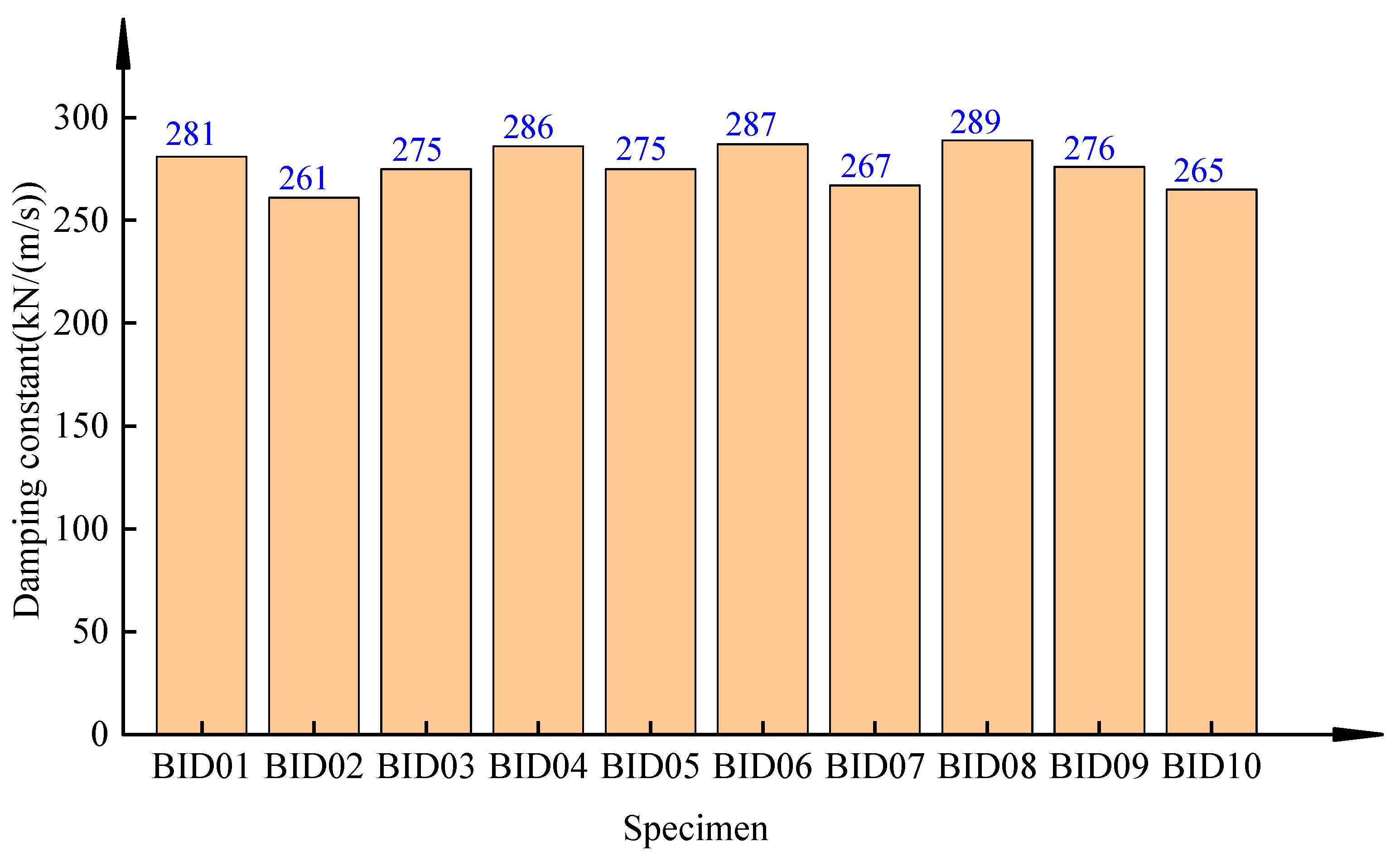
Figure 22 shows the damping constants C of the built-in dampers of BID 01 to BID 10. Figure 22 also shows that the average value of the built-in dampers’ damping constants is 276.2 kN/(m/s), and the maximum value is 289 kN/(m/s), with a deviation of 4.6%, which is below the allowable deviation of 15%. It shows that when the viscous damper is scaled down by a large proportion, its damping constant is quite stable.
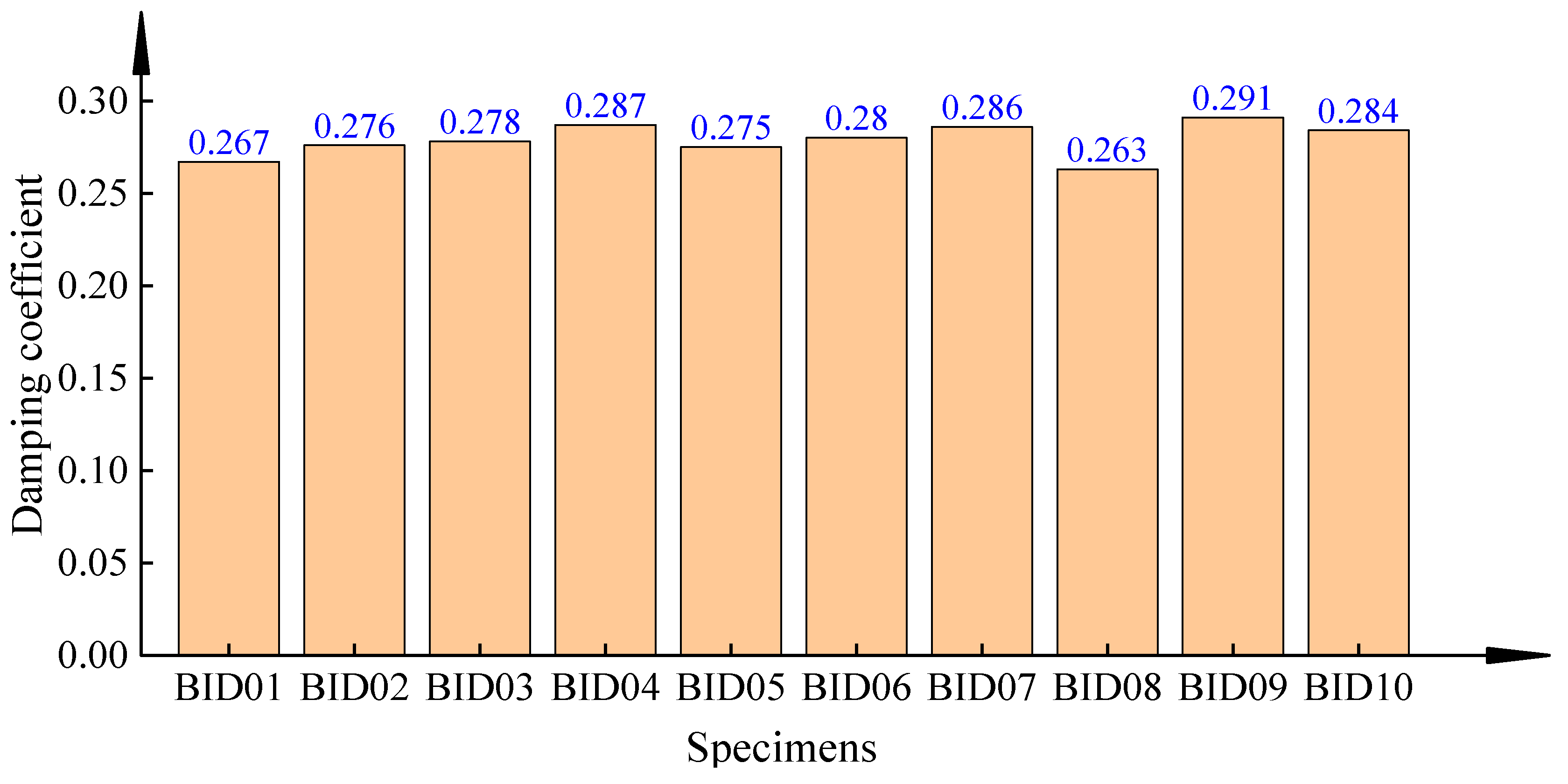
Figure 23 presents the damping coefficients 𝛂 of the built-in dampers of BID 01 to BID 10. From Figure 23, we can see that the average value of the damping coefficients of the built-in dampers is 0.2787, and the maximum value is 0.291, with a deviation of 4.4%, which is below the allowable deviation of 15%. It shows that when the viscous damper is scaled down by a large proportion, its damping coefficient is quite stable.
Table 4 summarizes the ratios of the maximum damping forces of the built-in dampers of BID 01 to BID 10 under different loading frequencies to the maximum damping force under the initial frequency. From Table 4, we can see that the ratios of the maximum damping forces of the built-in dampers under different frequencies to the maximum damping force under the initial frequency have a maximum value of 1.02 and a minimum value of 0.89. It shows that loading frequency does not significantly impact the CDHB’s maximum damping force, and the CDHB can provide a stable damping force under different loading frequencies.

5. Conclusions

In this paper, we have introduced a composite damped hinge bearing (CDHB), provided its structure scheme, and elaborated on its working principle. We have carried out the tests of the vertical bearing capacity and rotation performance on the composite bearing, as well as the axial tensile test on the built-in dampers, with the conclusions as below:
(1)
The CDHB is always in an elastic state within the design ranges of the vertical pressure and tension. The CDHB’s vertical deformation increases linearly with the increasing of pressure and tension and decreases with the increasing of the initial horizontal displacement;
(2)
Under vertical loading, the CDHB can always meet the requirement of reaching a rotation angle of 0.6 rad. Under the initial displacement of 0 mm, 25 mm, and 50 mm, the CDHB’s maximum pressure bending moment is 2850 kN·m, 2450 kN·m, and 2100 kN·m, respectively, and its maximum tension bending moment is 1190 kN·m, 1150 kN·m, and 975 kN·m, respectively. With the increase of the initial horizontal displacement, the CDHB tends to rotate more easily;
(3)
When the built-in damper is scaled down by a large proportion, its ultimate displacement, maximum damping force, damping constant, and damping coefficient are all stable. The built-in dampers can meet the bearing’s requirement of 100 mm displacement and provide a damping force of about 180 kN along the direction of the dampers.

Author Contributions

S.L.: Conceptualization, methodology, investigation. Z.H.: Software data curation, Writing—original draft preparation. T.O.: Validation, writing–reviewing and editing. Y.Z.: Supervision. All authors have read and agreed to the published version of the manuscript.

Funding

This research received no external funding.

Data Availability Statement

Data available upon request due to restrictions, e.g., privacy or ethical.

Acknowledgments

This research was funded by the National Natural Science Foundation of China grant number [52178466]. Moreover, the authors would like to express their sincere gratitude to the editor and the anonymous reviewers who significantly enhanced the contents of the study with their insightful comments.

Conflicts of Interest

The authors declare that there is no conflict of interests regarding the publication of this paper.

References

  1. Aydin, E.; Dutkiewicz, M.; Öztürk, B.; Sonmez, M. Optimization of elastic spring supports for cantilever beams. Struct. Multidiscip. Optim. 2020, 62, 55–81. [Google Scholar] [CrossRef]
  2. Gu, Z.Y.; Sun, Z.; Xu, Y.K.; Wang, Y. Vertical Seismic Response Analysis of Large Span Isolated Structures under Multi-Dimensional and Multi-Support Excitations. In IOP Conference Series: Earth and Environmental Science; Qingdao, China, 2019. [Google Scholar]
  3. Zhang, H.; Liang, X.; Gao, Z.; Zhu, X. Seismic performance analysis of a large-scale single-layer lattice dome with a hybrid three-directional seismic isolation system. Eng. Struct. 2020, 214, 110627. [Google Scholar] [CrossRef]
  4. Xu, Z.-D.; Wang, S.-A.; Xu, C. Experimental and numerical study on long-span reticulate structure with multidimensional high-damping earthquake isolation devices. J. Sound Vib. 2014, 333, 3044–3057. [Google Scholar] [CrossRef]
  5. Warn, G.; Ryan, K.L. A review of seismic isolation for buildings: Historical development and research needs. Buildings 2012, 2, 300–325. [Google Scholar] [CrossRef] [Green Version]
  6. Zhai, Y.; Fu, X.; Chen, Y.; Hu, W. Study on column-top seismic isolation of single-layer latticed domes. Sustainability 2019, 11, 936. [Google Scholar] [CrossRef] [Green Version]
  7. Li, X.; Xue, S.; Cai, Y. Three-dimensional seismic isolation bearing and its application in long span hangars. Earthq. Eng. Eng. Vib. 2013, 12, 55–65. [Google Scholar] [CrossRef]
  8. Shi, K.; Pan, W.; Jiang, Z.; Lv, J. Investigation of rotation and shear behaviours of complex steel spherical hinged bearings subject to axial tensile load. Struct. Eng. Mech. Int’l J. 2020, 73, 123–132. [Google Scholar]
  9. Karbakhsh, R.A.; Bin, O.I.; Binti, I.Z.; Ab-Malek, K. P-Δ and end rotation effects on the influence of mechanical properties of elastomeric isolation bearings. J. Struct. Eng. 2012, 138, 669–675. [Google Scholar] [CrossRef]
  10. Inaba, Y.; Terazawa, Y.; Matsui, R.; Kumagai, T.; Takeuchi, T. Cyclic loading tests on steel roof bearings and effects on roof responses. J. Struct. Constr. Eng. 2018, 83, 1129–1137. [Google Scholar] [CrossRef] [Green Version]
  11. Kim, B.C.; Park, D.C.; Kim, H.S. Development of composite spherical bearing. Compos. Struct. 2006, 75, 231–240. [Google Scholar] [CrossRef]
  12. Kim, B.C. Endurance and performance of a composite spherical bearing. Compos. Struct. 2009, 87, 71–79. [Google Scholar] [CrossRef]
  13. Fenz, D.M.; Constantinou, M.C. Spherical sliding isolation bearings with adaptive behavior: Experimental verification. Earthq. Eng. Struct. Dyn. 2008, 37, 185–205. [Google Scholar] [CrossRef]
  14. Cui, Y.; Gao, X.; Liu, H.; Yamada, S. Experimental study on seismic behavior of roof joint. Int. J. Steel Struct. 2018, 18, 1373–1383. [Google Scholar] [CrossRef]
  15. Chen, Z.; Ding, Y.; Shi, Y.; Li, Z. A vertical isolation device with variable stiffness for long-span spatial structures. Soil Dyn. Earthq. Eng. 2019, 123, 543–558. [Google Scholar] [CrossRef]
  16. Li, S.; Dezfuli, F.H.; Wang, J.Q.; Alam, M.S. Longitudinal seismic response control of long-span cable-stayed bridges using shape memory alloy wire-based lead rubber bearings under near-fault records. J. Intell. Mater. Syst. Struct. 2018, 29, 703–728. [Google Scholar] [CrossRef]
  17. Landi, L.; Grazi, G.; Diotallevi, P. Comparison of different models for friction pendulum isolators in structures subjected to horizontal and vertical ground motions. Soil Dyn. Earthq. Eng. 2016, 81, 75–83. [Google Scholar] [CrossRef]
  18. Ponzo, F.C.; Di Cesare, A.; Leccese, G.; Nigro, D. Shake table testing on restoring capability of double concave friction pendulum seismic isolation systems. Earthq. Eng. Struct. Dyn. 2017, 46, 2337–2353. [Google Scholar] [CrossRef]
  19. Calvi, P.M.; Calvi, G.M. Historical development of friction-based seismic isolation systems. Soil Dyn. Earthq. Eng. 2018, 106, 14–30. [Google Scholar] [CrossRef]
  20. Zhou, Y.; Chen, P. Shaking table tests and numerical studies on the effect of viscous dampers on an isolated RC building by friction pendulum bearings. Soil Dyn. Earthq. Eng. 2017, 100, 330–344. [Google Scholar] [CrossRef]
  21. Shang, J.; Tan, P.; Zhang, Y.; Han, J.; Mi, P. Seismic isolation design of structure using variable friction pendulum bearings. Soil Dyn. Earthq. Eng. 2021, 148, 106855. [Google Scholar] [CrossRef]
  22. Constantinou, M.; Mokha, A.; Reinhorn, A. Study of sliding bearing and helical-steel-spring isolation system. J. Struct. Eng. 1991, 117, 1257–1275. [Google Scholar] [CrossRef]
  23. Rezaei, A.; Van Paepegem, W.; De Baets, P.; Ost, W.; Degrieck, J. Adaptive finite element simulation of wear evolution in radial sliding bearings. Wear 2012, 296, 660–671. [Google Scholar] [CrossRef]
  24. Shrimali, M.; Jangid, R. Seismic response of liquid storage tanks isolated by sliding bearings. Eng. Struct. 2002, 24, 909–921. [Google Scholar] [CrossRef]
  25. Ozsarac, U.; Findik, F.; Durman, M. The wear behaviour investigation of sliding bearings with a designed testing machine. Mater. Des. 2007, 28, 345–350. [Google Scholar] [CrossRef]
  26. Whittaker, A.S.; Bertero, V.V.; Thompson, C.L.; Alonso, L.J. Seismic testing of steel plate energy dissipation devices. Earthq. Spectra 1991, 7, 563–604. [Google Scholar] [CrossRef]
  27. Tsai, K.C.; Chen, H.W.; Hong, C.P.; Su, Y.F. Design of steel triangular plate energy absorbers for seismic-resistant construction. Earthq. Spectra 1993, 9, 505–528. [Google Scholar] [CrossRef]
  28. Kaynia, A.M.; Veneziano, D.; Biggs, J.M. Seismic effectiveness of tuned mass dampers. J. Struct. Div. 1981, 107, 1465–1484. [Google Scholar] [CrossRef]
  29. Ministry of Housing and Urban-Rural Development of the People’s Republic of China. Spherical Bearing for Steel Building; GB/T32836-2016; Standards Press of China: Beijing, China, 2017.
  30. Ministry of Housing and Urban-Rural Development of the People’s Republic of China. Technical Specification for Seismic Energy Dissipation of Buildings; JGJ297-2013; China Architecture and Building Press: Beijing, China, 2013.
  31. Ministry of Housing and Urban-Rural Development of the People’s Republic of China. Dampers for Vibration Energy Dissipation of Buildings; JG/T209-2012; China Architecture and Building Press: Beijing, China, 2012.
Figure 1. Schematic structural diagram of the CDHB: (a) overall view and (b) component.
Buildings 13 00383 g001
Figure 2. Geometric dimensions of the tested CDHB: (a) perpendicular to the axis of the built-in damper and (b) along the axis of the built-in damper.
Buildings 13 00383 g002
Figure 3. Geometric dimensions of the built-in dampers.
Buildings 13 00383 g003
Figure 4. Whole testing CDHB unit.
Buildings 13 00383 g004
Figure 5. Schematic diagram of the whole CDHB’s loading test set-up.
Buildings 13 00383 g005
Figure 6. Schematic diagram of the loading set-up of the built-in dampers.
Buildings 13 00383 g006
Figure 7. Loading scheme of the vertical loading capacity test.
Buildings 13 00383 g007
Figure 8. Loading scheme for the pressure rotation angle and tension rotation angle test.
Buildings 13 00383 g008
Figure 9. Loading of the maximum damping force.
Buildings 13 00383 g009
Figure 10. Pressure-displacement curves.
Buildings 13 00383 g010
Figure 11. Compression test of the CDHB.
Buildings 13 00383 g011
Figure 12. Tension-displacement curves.
Buildings 13 00383 g012
Figure 13. Picture of the CDHB’s tension test.
Buildings 13 00383 g013
Figure 14. Rotation angle-bending moment curves when the CDHB is under pressure.
Buildings 13 00383 g014
Figure 15. Compression rotation angle test.
Buildings 13 00383 g015
Figure 16. Rotation angle-bending moment curves of the CDHB under the action of tension.
Buildings 13 00383 g016
Figure 17. Picture of tension rotation angle test.
Buildings 13 00383 g017
Figure 18. Ultimate displacement.
Buildings 13 00383 g018
Figure 19. Ultimate displacement curve of BID 03.
Buildings 13 00383 g019
Figure 20. Maximum damping forces.
Buildings 13 00383 g020
Figure 21. Maximum damping force curve of the BID 03 testing section.
Buildings 13 00383 g021
Figure 22. Damping constants.
Buildings 13 00383 g022
Figure 23. Damping coefficients.
Buildings 13 00383 g023
Table 1. Mechanical parameters of the CDHB.
No.Parameter TypeNumerical Value
1Vertical compression property5000 kN
2Vertical tension property2000 kN
3Horizontal load-bearing capacity200 kN
4Allowable rotation angle0.06 rad
5Unidirectional sliding displacement100 mm
Table 2. Parameters of the built-in dampers.
No. Parameter TypeNumerical Value
1Damping constant C kN/(m/s)300
2Design stroke(mm)±125
3Design damping force (kN)100
Table 3. Test conditions.
Working ConditionWorking Condition DescriptionInitial Displacement
1Pure compression0 mm
225 mm
350 mm
4Pure tension0 mm
525 mm
650 mm
7Compression rotation0 mm
825 mm
950 mm
10Tension rotation0 mm
1125 mm
1250 mm
Table 4. Ratios of the maximum damping forces under different frequencies to the maximum damping force under the initial frequency.
Force DirectionF1.3f1/Ff1F1.6f1/Ff1F1.9f1/Ff1F2.1f1/Ff1
BID 01+0.980.970.950.96
0.991.020.890.9
BID 02+0.960.970.940.96
0.8910.90.92
BID 03+0.970.970.950.97
0.990.950.90.92
BID 04+0.980.950.950.94
1.011.010.90.92
BID 05+0.980.970.950.95
0.991.020.890.9
BID 06+0.980.950.950.96
1.0110.90.92
BID 07+0.980.970.940.94
110.90.91
BID 08+0.980.950.950.96
11.020.90.92
BID 09+0.980.960.950.93
0.991.020.90.92
BID 10+0.970.960.950.96
1.011.020.890.9
Disclaimer/Publisher’s Note: The statements, opinions and data contained in all publications are solely those of the individual author(s) and contributor(s) and not of MDPI and/or the editor(s). MDPI and/or the editor(s) disclaim responsibility for any injury to people or property resulting from any ideas, methods, instructions or products referred to in the content.