1. Introduction
3D information has dominated the world of building modeling using Building Information Modeling (BIM) for more than a decade [
1]. BIM includes the 3D representation of the building’s semantic and geometry information and the relationships of the elements [
2]. A series of standards are introduced to represent the BIM data model; the most well-known digital standard of BIM is the Industry Foundation Classes (IFC) released by the International Alliance for Interoperability (IAI), known as BuildingSMART Alliance (BSA) [
3]. The IFC model is an object-oriented data model incorporating 3D geometry, spatial relationships (topology), quantities, and building element properties (semantic). IFC facilitates the interoperability problems in the different disciplines and shares almost all the building components in the construction and building management domain [
4,
5]. Different disciplines, such as facility management and energy efficiency studies, need accurate geometry, semantics, and topology as preliminary information to lead to reliable and accurate results. Furthermore, the 3D information in IFC models has received significant interest in today’s application domain in smart cities and smart buildings [
6]. Recently, IFC as a 3D data source for Building Energy Consumption Estimation (BECE) has gained momentum, according to a study by [
7].
Indeed, BECE vitally depends on the geometry, topology, and material information of the building’s elements to recognize the spaces in a building with high energy demand [
8,
9], which leads to evaluating different building design scenarios and operation plans. The physical modeling and the data-driven approach are widely used for BECE [
9]. Physical models (also known as white-box models) rely on thermodynamic rules for detailed energy modeling and analysis. These models calculate building energy consumption based on detailed building and environmental parameters such as building physical details, construction schedules, and HVAC design [
8]. On the other hand, data-driven methods estimate building energy consumption based on learning from historical data and building properties [
9,
10]. However, two shortcomings limit the BECE physical models. First, the high number of required input physical parameters that need to be measured by deploying sensors, and second, they are not designed to use geometry information, one of the influential parameters to estimate energy consumption [
11,
12].
On the other hand, data-driven methods can accept BECE-based analysis hyperparameters, making them flexible in using various data sources in their process [
5]. Despite extensive studies on data-driven methods, employing the IFC model as a 3D model remains poor due to its complexity and incompatibility with data-driven methods such as machine learning algorithms. This paper intends to answer the research question: How can the IFC data model be compatible with BECE data-driven model? Indeed the IFC model includes the indoor environment’s primary semantic, geometry, and topology information which are of considerable interest for data-driven methods. Especially by describing the indoor space concept (known as the IfcSpace class) in the IFC standard model and defining spatial links between them open the potential for BECE analysis in different parts of the building. Indeed, it is possible to create a space-based graph directly to analyze the energy transfer between them. In this graph, the nodes denote spaces in which the property information of each space (node) is defined as vector information assigned to the node. An edge in the graph connects a pair of spaces and captures the spatial relationship of spaces if there is any energy transfer [
13]. Graphs have also begun to play a crucial role in machine learning to incorporate real-world objects with relationship information for knowledge extraction and phenomenon prediction [
14]. BECE analysis based on machine learning algorithms in space scale depends on indoor geometry, semantic, and relationship parameters such as relative compactness, shading coefficient (SC), the overall heat transfer coefficient of building walls (R-Value), roof heat transfer coefficient (R-Value), the absorption coefficient for solar radiation of exterior walls, window–wall ratio (WWR), height of space, orientation, and glazing area distribution [
9,
15]. Unfortunately, the spaces (IfcSpace) in most existing IFC models have inaccurate geometric information and space-based topological descriptions for BECE-based analysis. Therefore, the mentioned feature information is not explicitly available in the IFC model and needs to be computed from a combination of semantic and geometry information. Moreover, possible inconsistency between geometric and semantic information causes inaccurate results when using the IFC dataset in machine learning algorithms. Therefore, a study is emergent to bridge this gap, consider existing models’ limitations, and propose a solution for the IFC data model’s compatibility with machine learning algorithms.
This paper proposes a framework to generate an object-oriented data model as an intermediate data model to translate the IFC model to the BECE space-based graph, including BECE-related information and spatial relationship between IFC spaces. In this research, we employed IFC specification 4.0.2.1 under ISO 16739-1:2018 because the IFC models are available under this version for the case study [
16]. The proposed framework extracts and calculates implicit BECE-related information by introducing new objects, such as a wall’s inner and outer face objects, roof, window, floor, and related geometry information. At the same time, the framework introduces accurate topological information, such as the spatial relationship between spaces horizontally and vertically. Furthermore, in contrast to other studies considering just the binary relationship between the IFC elements, the framework calculates the weighted relationship using energy transfer between the spaces. Undeniably, the advantage of using the proposed intermediate object-oriented data model is the possibility of extracting implicit BECE-related information from IFC by preserving the spatial relationship (topology information) between the spaces. Thus, the framework extracts the complex IFC data model, including the buildings’ meaningful semantics for BECE, geometry, and spatial relationship, into a BECE-based graph. The main benefits of the proposed methodology are: (1) to enable building space objects in IFC to be automatically translated into a BECE-based data model; (2) to enhance the hidden values in the original IFC to make it usable in building energy estimation without human interference; and (3) to develop a more reliable and accurate BECE space-based graph from IFC models to be compatible with machine learning algorithms.
The paper is structured as follows.
Section 2 provides state-of-the-art, while
Section 3 lists the challenges and shortfalls.
Section 4 discusses the suggested methodology, which enables us to consider the indoor 3D space and its topology data.
Section 5 contains the data sources, case studies, and outcomes. Finally,
Section 6 summarises the lessons learned, concluding remarks, and path for further research.
2. Related Work
Data-driven methods benefit from developments in machine learning, such as providing flexibility and reliability in modeling and forecasting building energy consumption [
15,
16]. Therefore, many studies have been conducted on the semantics and geometry data exchange between BIM and BECE using standard data schemas (IFC). Briefly, three types of solutions can be distinguished [
17,
18].
Jeong et al. (2014) in [
22] applied type one in their simulation using REVIT API and the Modelica Building Library. The most significant disadvantage of this strategy is the mismatch between the two environments and the reliance on a particular version of proprietary software. Cemesova, Hopfe, and McLeod (2015) in [
23] employ the second type in their analysis and use commercial software to convert the BIM format to the gbXML data model. This model has restricted geometry-defining capabilities even though it keeps the topology information of the BIM data (e.g., preserving only rectangular shapes based on the element centerline). Therefore, it can support convex polyhedron shapes and ignore non-convex polyhedrons, leading to a non-accurate estimation of the building energy consumption [
24]. Most parts of the third type of solution focus on geometry representation despite enriched information from the IFC schema, such as the face geometry properties and space topological information. All of them are considered implicit in the Type III solution.
Consequently, the IFC model’s complexity and incompatibility with data-driven methods restrict being used in BECE data-driven methods. Furthermore, most published approaches only concentrate on one particular component of BIM data (for example, geometry or HVAC) and employ conventional physical simulation engines as a result of the difficulties noted with using the IFC model in BECE data-driven methodologies (e.g., EnergyPlus) [
25]. Therefore, utilizing an efficient data model to have the following three characteristics is necessary: (1) the capability of the data model to be connected to different data sources; (2) the capability of the data model to preserve geometric, semantic, and relationship information; and (3) compatibility of the data model with the machine learning algorithm.
3. Challenges in Extracting the BECE-Based Geometry, Semantic and Topology Information from the IFC Model
The current state of the art in estimating building energy consumption recognized the beneficial use of IFC models for extracting the building semantics, geometry information, and 3D spatial relationship between the spaces [
25,
26]. Indeed, efficient 3D analysis of building energy consumption relies on the indoor environment’s semantic information, the geometric description of the IFC entities, and their spatial relationships. The geometry and material information of the entities such as walls, windows, roof, and floor are the main entities of each room in IFC, affecting the room’s heat gain and loss. Therefore, taking the precise geometry and room’s properties, such as material information of these entities for each room, is necessary. Most IFC-based building energy modeling relies on the information stored in the model. However, incomplete or erroneous implementation of the IFC and implicit topological information, typically found in many IFC export modules, cause inaccurate geometry information, such as each space’s wall and window area. Additionally, recognizing accurate topological information, such as the spatial relationship between the spaces, is hard to extract from the IFC models. These errors generate an invalid graph in the perspective of extracting BECE-based information and wrong space spatial relationships. In this situation, sophisticated geometric processing is required to produce the desired graphs from only geometric data. In detail, the challenges mentioned above regarding the spaces’ geometry and topology information in the IFC model are categorized as two main problems: invalid geometry information in the IfcSpace object and inaccurate space adjacency (topology) information described in the following sections.
3.1. Illustrating Invalid Geometry Information in the IfcSpace Object
To evaluate the energy consumption of the different spaces of the buildings using data-driven approaches and the IFC model, we use the concept of space representing the concept of room [
25]. Space splits the buildings into different parts and represents an area or volume bounded. Therefore, the geometry information of each space and its related entities, such as windows, walls, doors, roofs, and floors which significantly influence the energy load, should be extracted accurately to improve a room’s energy efficiency analysis [
27]. The primary geometry information of these entities is listed as the Window–Wall Ratio (WWR), Exterior–Wall Ratio (EWR), Interior–Wall Ratio (IWR), Floor–Room Ratio (FRR), and Roof–Room Ratio (RRR), the total area of the room, and the total height of the room.
At the high-quality IFC model, it is sufficient to rely on the query of IfcSpace objects described in an IFC model to retrieve 3D indoor geometry information to extract each room’s wall, window, roof, and floor geometry properties.
Figure 1 illustrates an example of high-quality semantic and geometral modeling of IfcSpaces and the schema of IfcSpace in which the walls are split geometrically for each room (yellow lines). In this model, a semantic-based query using the IfcOpenShell library extracts accurate geometry information, such as the wall area for each room, because the walls are split geometrically based on the boundary of each space. However, it is common for Ifcspace objects to contain the erroneous entity’s geometry despite the standard definitions and implementation instructions established to point toward appropriate IFC models. Most IFC models do not have the second boundary definition of the objects (split geometry) for spaces and inaccurate geometry calculations [
28].
Figure 2a represents an IFC model with the non-topological definition of walls and windows for the corresponding spaces. This figure shows a shared wall (W143) between three spaces (S202, S201, and S203). In this case, the query returns an equal value of 3.84 m
2 of the wall-143 for each room, equal to the total area of the wall-143 because it is not split based on space’s boundaries. If we rely on this type of erroneous geometry value and apply them in the BECE process, it impacts the analysis of each room’s energy consumption.
Additionally, the window is a critical entity in a building with a central role in energy gain or loss. In this regard, windows are revealed to impact room energy consumption and contribute to more than 10% of the building’s energy load. If a room includes an exterior low-efficient window, the room’s energy loss is increased drastically. Therefore, the energy consumption of a room directly depends on the window size, location, and resistance rate [
29]. For example,
Figure 2b represents a shared window (WIN923) between S155 and S156. Performing a query from the existing IFC model returns an equal area value of window (WIN923) for both rooms.
In contrast, the window size in S156 is significantly larger than in S155. Therefore, the impact of window-923 on the heating loss and gain in room-156 is more than its impact on room-155, which is not recognized if we rely on the current IFC query result. This leads to the necessity of geometric computation to extract accurate geometry information for space geometry information before using them in data-driven methods.
3.2. Identifying Inaccurate Space Adjacency (Topology) Information in the IFC Model
Two spaces have adjacency in a 3D model when at least one shared wall, window, roof, or floor between them exists. In the domain of BECE, the energy transferred between the adjacent rooms affects the energy demand of each room. For instance, the heating loss rate from the warm area to the cold area increases noticeably if a room shares a wall or floor (such as the basement) with a cold room (with low energy efficiency). Therefore, extracting accurate adjacent information is essential. Nevertheless, the IFC semantic-based query cannot return the valid adjacent information because of each space’s invalid (non-split geometry) wall, roof, window, and floor geometry.
Figure 3 illustrates the instance of this error which results in the wrong adjacency list.
Table 1 describes a semantic-based query using the current information in the IFC model. It employs the
BoundedBy property of space objects to retrieve the
IfcWall and
IfcCurtainWall objects bounded to each space. By iterating through all space around the target space (B202 in
Figure 3), the neighbor space objects are added to the adjacent list and considered adjacent. The result shows the wrong adjacent spaces for the target room because there is a continued wall-143 between the target room, rooms A202 and B203. Indeed, no geometrical relationship is available between them, which causes no energy transfer; however, the IFC semantic query considers their adjacent spaces. Therefore, retrieving the topological information based on the semantic query from the IFC model is inaccurate and causes erroneous results for generating the BECE space-based graph.
On the other hand, calculating the quantified value of space adjacency (weighted adjacency) is another parameter ignored in recent studies. Most researchers rely on binary space adjacency to find if two spaces are navigable by recognizing any opening object, such as a window or door between two spaces, as indoor navigation applications. However, in BECE analysis, the weight of this relationship is important because the amount of transferred energy from one room to another is directly related to the surface area of the shared wall, window, roof, floor, and material information. For instance, space A201 in
Figure 3 is a cold room on this floor and significantly impacts the heating transfer to its adjacent spaces. In principle, the heating transformation from room A204 to room A201 (from a warm area to a cold area) is more than the heating transformation from A205 to A201 because of the differential in the shared wall area. Unfortunately, this information is not explicitly available in the IFC model. They have to be derived from the available entities using advanced geometric processing and material isolation information to obtain the desired weighted graphs. Hence, developing a framework to translate the IFC model into a weighted space-based graph with accurate feature values compatible with BECE-based data-driven methods.
4. Methodology
This research proposed a framework to generate a BECE-based Weighted space-based Graph (BECE-WG) to solve the compatibility issue between the IFC data model and graph-based machine learning algorithms. The graph represents a collection of interlinked IFC entities and their properties.
BECE-WG arranged the IFC dataset into connected graph structures, allowing for the integration and linking of data from several sources. In order to create a data structure connected to many datasets and appropriate for machine learning methods, this study uses the idea of converting 3D building data models (IFC) to a graph. The proposed graph contains space (room) object information as a node and their relationships with neighbor rooms as the edge. The BECE-based information of each space is extracted and calculated geometrically and semantically and assigned as a feature vector to each node in the graph. Different machine learning tasks such as supervised and unsupervised classification, node clustering, graph clustering, and node label prediction can employ the generated BECE-WG for building energy analysis. The framework has four main components: (1) BECE-based Object-Oriented data model, (2) Extract 3D Geometry Features, (3) Extract Space Adjacency Information, and (4) Generate BECE Weighted Space-based Graph. Each component includes some detailed steps, which are represented in
Figure 4.
4.1. BECE-Based Object-Oriented Data Model
An object-oriented data model is proposed by introducing BECE-based building objects with the superclass of building and story classes. Story class includes space objects and child objects such as the wall, window, floor, roof, and face objects representing three-dimensional objects. In this research, fmw is used as a prefix for the proposed framework object (fmw-object), and IFC (IFC-object) is employed as a prefix for standard IFC objects.
Figure 5 represents the proposed BECE-based data model, including the objects, properties, functionalities, and relationships. The proposed objects in the BECE framework include three main parts of properties, child objects, and functions. The property section encompasses the unique id, energy transfer properties such as material information, and thermal Resistance Value (R-Value). It also includes accurate geometry information such as area and volume for wall, window, floor, and roof objects for each space. The
Section 2 contains the child objects, which define the relationship between the framework objects. This section includes a single object or a list of objects. The relationship between the building entities can be defined by assigning the child object to the parent object, improving the query process, and extracting information from the proposed data model. For example, we proposed an
fmw-face object as a child object of the
fmw-wall to extract accurate geometry information on both sides (face of the wall) for each space. By adding the
fmw-space object as a child object in the
fmw-face object, we can find the corresponding space (grand-parent) of the specific face with a simple query process. However, this process leads to a complicated query in the IFC model to access the higher hierarchical objects (e.g., parent of parent objects).
The
Section 6 of the proposed data model for objects is their functionality. The functions associated with each object calculate geometry properties (e.g., area, volume, etc.), semantic property values (e.g., the type of materials) called
Extract_3DGeometry_Features, and identify the topological relationships between spaces, called
Find_Adjacent_spaces. However, as discussed in
Section 3.1, the geometry features cannot be extracted precisely by the IFC semantic-based query. Therefore, we proposed the
Extract_3DGeometry_Features (
Section 4.2) function for space objects to apply the face partitioning concept to extract accurate face geometry information of wall, window, roof, and floor objects in each space, as explained in
Section 4.2 in detail.
The proposed data model tackles the space-adjacent challenges in the IFC model (
Section 3.2) and improves the space-based relationship information between building objects in the IFC model. The relationships are defined based on the collection of child objects associated with each
fmw-object. For example, an
fmw-space object includes a collection of
fmw-wall, and each
fmw-wall object includes a collection of
fmw-face as child objects. Therefore, by initializing the
fmw-space object and calling
the Find_Adjecent_Spaces function, adjacent spaces for the target space are calculated and populate the
Neighbor-space list of the
fmw-space object. Therefore, we can apply a standard object-oriented query to access all wall, face, and adjacent spaces objects corresponding to each space.
The pseudocode code in
Table 2 describes
fmw-space object initialization and calculates the space properties and adjacent list by calling both
Extract_3DGeometry_Features and
Find_Adjecent_spaces functions.
Section 4.3 discusses
Find_Adjecent_spaces in detail.
4.2. Extract 3D Geometry Features
The main goal of this section is to extract accurate geometry information such as Exterior Window–Wall area Ratio (EWWR), Exterior–Wall area ratio (EWR), Interior–Wall area ratio (INWR), Floor–Room area Ratio (FRR), and Roof–Room area Ratio (RRR) for building entities for each space. A closed volume characterizes a space in the IFC model of bounded walls, roof, and floor (space-bounding objects). Each bounded object includes a collection of faces in which a face is composed of a wire. The wire consists of edges and vertices. We used this granular information in IFC to create the
fmw-face object for each space’s walls, windows, roof, and floor to solve invalid space-based geometry issues, as mentioned in
Section 3.1. The geometry granularity description of faces allows us to generate an
fmw-face for each space, considered an inner face for the target space. The steps of creating face geometry consist of: (1) Extract the space’s bounded objects (walls, windows, roof, and floor); (2) Extract the inner and outer faces of the bounded objects for each space; and (3) Define a new wall (
fmw-wall) object and face (
fmw-face) object for each space in the building. These steps extract the accurate geometry information for convex and non-convex spaces (non-convex hydron). Many previous studies focused on extracting the geometry information from the IFC. However, their solutions were limited to extracting the geometry information for convex spaces as a boundary box (bbox). In reality, the IFC model includes convex and non-convex polyhedrons. Therefore, we dealt with this challenge by proposing a solution to extract the accurate geometry of bounded objects for convex and non-convex polyhedron spaces.
4.2.1. Extract the Space’s Bounded Objects
In this method, we expect the IFC model to accurately include the wall-required information, such as the classes
IfcSpace,
IfcRelSpaceBoundary,
IfcConnectionGeometry, and
IfcWallStandardCase. Each space’s bounding walls can be listed using the
BounedBy function, which returns
ifcRelSpaceBoundary elements, including the walls and
ifcCurtainWalls. The ifc_wall_list includes all walls and curtain walls corresponding to ifcSpace. For instance, if we consider space-B202 as the target space, the query results in
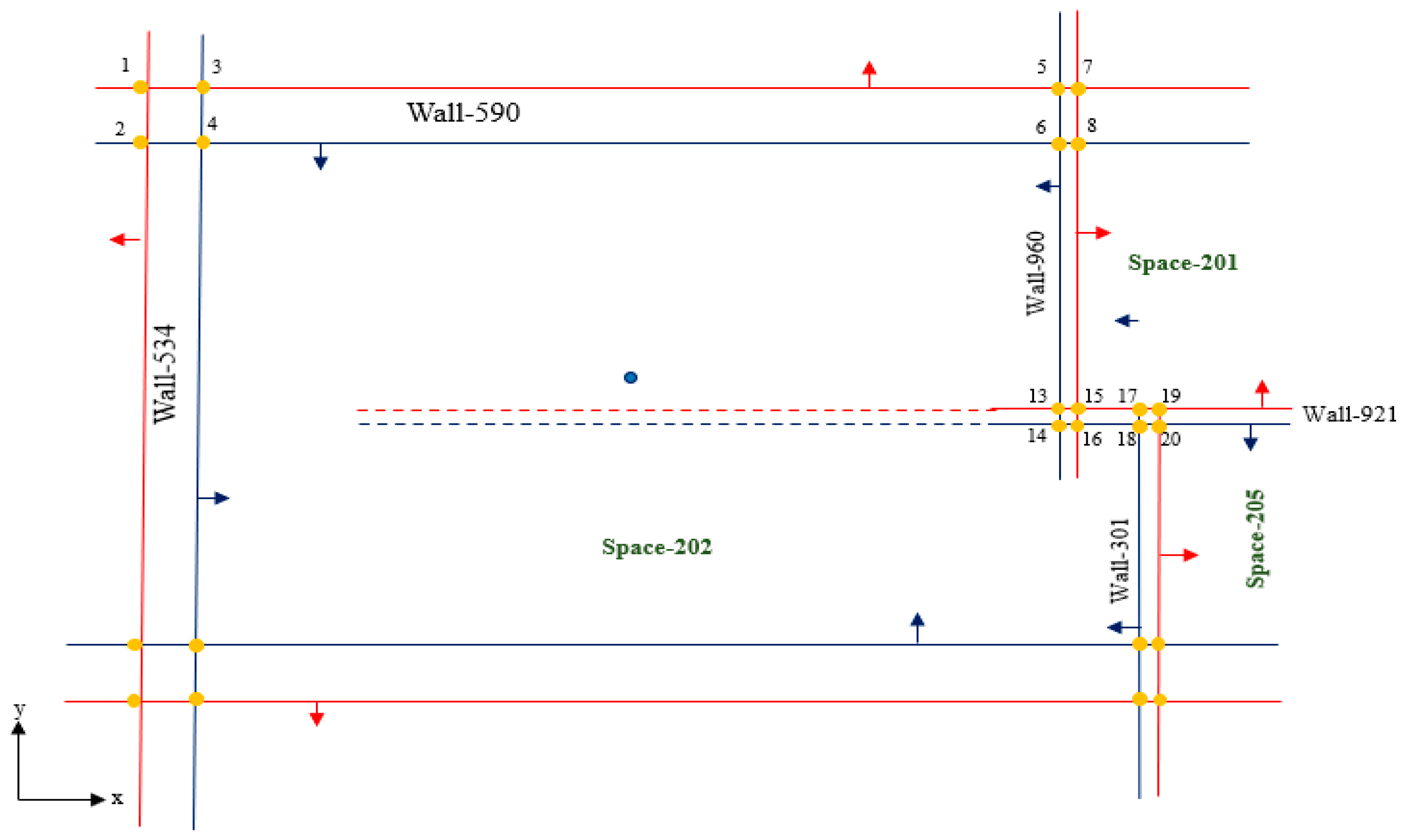
Table 3 are listed as two exterior walls: wall-534, wall-590, and four interior walls: wall-960, wall-921, wall-301, and wall-239.
4.2.2. Extract the Inner and Outer Faces of the Bunded Objects
The reason for extracting the walls’ inner face is to calculate the accurate geometry information (wall area for space). A shared wall between two spaces can have different areas based on the face geometry on each side.
Figure 6 represents the 2D perspective of space-202 and the two inner and outer faces, planes, and normal vectors of each face for wall-235. The inner and outer face extraction is performed in two main steps.
Step I: In this step, we need to determine which face of the wall towards the inner of the space becomes part of the space’s bounding volume. The IFC model has several shapes: Solids, Shells, Faces, Wires, Edges, Vertices, and Compounds. We can iterate over the faces that bound the solid shape. Then, we can get a reference to the face’s underlying surface. We can determine the plane for each face by knowing a point that belongs to the face (
)) because the IFC model is composed of planar geometry. Therefore, we know that the face’s surface conforms to a plane and a vector perpendicular (
a,
b,
c) to plane
n. Equation (1) illustrates the plane question for all faces of the wall for space:
By iterating through ifc_wall_list (as presented in
Section 4.2.1), all faces for the walls for a specific space are listed, and their planes are calculated by selecting a node on the surface and its normal vector (Equation (1)) and storing them as a child object of frm_wall object (frm_face_list).
Figure 7 shows the semantic query to extract the bounding walls of ifcSpace and store them as a list of walls for a specific space (room).
Figure 7a illustrates the face representation, and
Figure 7b explains the framework’s fwm_wall object’s hierarchy. For example, the sample wall in
Figure 7a illustrates six faces. To extract two prominent faces (inner and outer faces), the method iterates through the faces and calculates the area of each one.
The faces are sorted in ascending order based on their area value, and the two first faces are chosen as the main face objects. To find out the inner and outer face objects between these two faces, we applied the distance from plane method to calculate the distance of space’s center point (
Figure 6, space-202) from the plane of these two faces. The face with the minimum distance from the space’s center point is considered the inner face, and the second is assigned as the outer face object. This method has a high accuracy rate in distinguishing between the inner and outer faces of convex polyhedron spaces. However, this method has incorrect results returned for some walls in non-convex polyhedron spaces.
Figure 8 represents an example of this non-convex polyhedron space. The outer face of wall-921 is closer to the space’s center point than the inner face. Therefore, the algorithm assigns the outer face (red dashed line) as the inner face object, which is incorrect.
Consequently, we need additional conditions to increase the result accuracy and correct the wrong faces assignment. The next step describes this process. Additionally, after finding the first step of the inner and outer faces, we can explore which portion (polygon surface) of the plane belongs to the target space. To do that, all extracted planes of inner faces are intersected (Equations (2) and (3)).
Therefore, there is no intersection for those planes whose normal vector’s dot product is zero, and the algorithm considers them parallel faces. By looping through the frm_face_list, all pairwise planes corresponding to each face are considered the vector equation of the intersection line. (Equation (2)) is calculated by the cross-product of the normal vectors of the given planes. To do that, a point (
on the line of intersection is necessary. Therefore, the equations of the given planes as a system of linear equations (Equation (3)) are employed and set the z = floor as the z-value in this equation. Then, calculate the intersected line equation and store the intersected line in an array list (line_arraylist).
By the intersection of walls, windows, roof, and floor with the target face, four lines are extracted to delineate the polygon surface of each inner face. Each inner space’s polygon geometry is determined using this result, and geometry information such as area, perimeter, and space boundary (wire) for each wall can be calculated. The intersection method helps solve the issue regarding inaccurate geometry information when there is a continuous multi-space shared wall in the IFC model, as previously mentioned in
Section 3.2. The face intersection method can reach the accurate geometry of faces and obtain the accurate geometry of each wall, roof, and floor for the target space.
Step II: At this step, post-processing of inner and outer face extraction is applied to rectify the possible error in recognizing walls’ inner and outer faces. Therefore, we use the advantage of wall partitioning (fmw_face object) results to investigate the potential error for some walls in a non-convex polyhedron room. We apply the ray-tracing intersection method for all recognized inner faces in the first step to solve mentioned issue. By iterating through to all recognized inner faces from step 1, we can make a ray-crossing line for each face using the face center point and its plane’s normal vector. Then, intersect the created ray-cross (line) with all inner faces and find the intersection point (
x,
y,
z). If the intersected point is at least inside one of the inner faces’ polygon, the target face is an inner face. It is considered an outer face if it does not meet this condition.
Figure 9 illustrates a sample of applying the ray-crossing algorithm to rectify the extracted inner and outer face for wall-921.
4.3. Extract Space Adjacency Information
The adjacent space analysis is a critical spatial analysis in BECE to measure the effect of the neighbor spaces on each room’s energy transfer. Therefore, in the BECE application, it is necessary to investigate the adjacent spaces affected by different adjacent degrees when a room has high energy consumption. However, recent research does not explore the algorithm to extract the accurate space adjacent and the quantified weight of adjacency from the IFC model [
29,
30].
Section 3.2 discusses the problem of the semantic query from the original IFC model in extracting space-adjacent information. It implies that the current methods of extracting space adjacents are inaccurate because they assume that if two walls corresponding to two spaces have a shared edge in the floor plan, they are adjacent. The IfcSpace can obtain information about the nearby walls, but since numerous IfcSpace objects can share a wall, it is not realistic to assume that the IfcSpace’s adjacency relations can be obtained by using the same wall. In this research, we develop our space’s adjacent extraction method on the inter-relationships among IfcSpaces to extract the quantified space adjacent extraction and use this method as a node relationship information (edge) to generate the final graph. As we discussed in
Section 4.1, the object in the proposed framework includes some functions to extract the information not available in the IFC model, such as finding adjacent spaces for each space. The proposed method encompasses three steps. First, we extract all faces related to each wall in a space using a query from framework wall objects, not the IFC objects. Second, select the faces whose normal vector of planes has the opposite direction from the target face. Finally, the polygon intersection method detects if two faces are intersected.
4.3.1. Extract All Faces Corresponding to fwm_wall
The proposed framework wall object (fmw_wall) lists fmw_face child objects. First, the face objects in this list are calculated and populated based on the proposed method in
Section 4.2. Next, we define and create the face object by extracting the fmw_face object and assigning it as a child object for each wall in the IFC model. This object is not defined explicitly in the IFC model, but the proposed framework makes it available for BECE analysis.
Figure 7a describes the query syntax of extracting all faces (both sides) for wall-239. Line 1 to 3 of the syntax code shows how to apply a simple query to access eight fmw_face objects for wall-239.
4.3.2. Select the Faces to Intersect with the Target Face
By accessing all faces and their polygon geometry, the algorithm filters the faces to detect any intersection between the target_face (red face in
Figure 10—Side 1). Therefore, the dot product of the plane’s normal vector of the target face and the other faces is calculated, and those with a dot product value of more than zero are selected for the intersection test (yellow faces in
Figure 10—Side 2).
4.4. Inner and Outer Face Intersection
This step applies a pairwise intersection between the outer faces extracted from the previous section and the target face. The research assumes all faces are a convex 2D polygon; accordingly, we apply the 2D polygon intersection method to detect if two faces are intersecting. However, we need two polygons on the same plane to apply the intersection method. Therefore, we project the outer face polygon on the target face’s plane, then apply an intersection between the two polygons.
Figure 11 represents the projected polygon schema (dashed red line) of the outer face of the target plane. The projected polygon intersects with the target face’s polygon to find the area of intersection (
Table 4, lines 8, 9, and 10).
Table 5 explains the calculate_polygon_intersection_area method, which uses the shapely open-source library to calculate two polygons’ intersected areas. Consequently, just one face from wall-239 intersects with the target face, and the parent object of that face (fmw_space) is recognized as one of the adjacent spaces. Using the proposed method in
Section 4.3, we can extract both the 3D adjacent spaces for each space and the area value of adjacency. Finally, this method is applied on the floor and roof to find the adjacent spaces on different floor levels with calculated the shared area value.
Calculate the Spaces’ Adjacency Weight
The edges in our proposed graph are representative of the adjacent space relationship. The BECE-based graph is a weighted graph in which weights reflect the relative importance of the rooms’ relationships. In other words, some links between nodes have lower weights (low importance), and others have higher weights (high importance). For example, suppose two rooms have more energy transfer in our application. In that case, the relationship between those rooms is more important than two other rooms with a low rate of energy transfer. The energy is transferred between two rooms through the walls, roofs, floors, and windows. Each of these building elements comprises several layers with different materials. The energy transfer of each building element is determined by the thermal resistance value (R-Value). In fact, the R-value assesses how well a two-dimensional barrier, such as an insulation layer, a window, a wall, or a ceiling, resists heat conduction [
31]. Therefore, we introduced a wight for the room relationship by calculating the barrier’s R-Value and the shared area value. Equation (4) describes the proposed weight value of edges in a BECB space-based graph. The
shows the importance value of the two room’s relationship. Share area is the common area value of rooms
n1 and
n2. The
is the sum of the R-Value for n number of barriers between two rooms.
4.5. Generate BECE-Based Weighted Space-Based Graph
After creating fmw_face objects and extracting the BECE-based attributes and relationship information, a new method is developed to transfer the
fmw-face objects to a weighted BECE space-based graph. This method constructs the adjacency matrix following and the weighted space-based graph based on the
fmw-face object list from
Section 4.2 and
Section 4.3. It includes three main steps. First, the Normalization Function (NF) is used to normalize the feature values. The normalizing must produce common scale feature values for machine learning algorithms since each parameter has a different scale. Therefore, we applied the min-max normalization method to normalize the input feature values. The second step generates the adjacency matrix using the list of adjacent objects (
fmw_space). Indeed, the adjacency matrix represents the graph as a square matrix with the size of n * n (n: number of nodes). In the last step of this process, the function is designed to iterate through the spaces to find the space’s adjacency and assigned weight value. In this step, the space-based graph was created utilizing the adjacency matrix and six feature values embedded as each node’s properties using the Python NetworkX module [
32]. The generated graph is homogeneous because all nodes have equivalent types (room) and similar edges to the room’s neighborhood. Therefore, the BECE space-based graph is a compatible data model for future space-based energy consumption analysis using a graph-based machine learning algorithm (Graph-ML).
4.6. Measuring Accuracy for Validation
The validity of the proposed algorithm in extracting geometry information is verified using the Root Mean Error (RMSE), a standard way to measure a model’s error (or level of accuracy) to evaluate the model’s estimated values for quantitive data [
33,
34]. Indeed, the geometry (area) of walls, windows, roofs, and floors for all spaces in the two test cases are extracted by BIMVision software which is considered a ground truth value. Then, the RMSE value is calculated using Equation (5) [
35] for the extracted geometry information of building elements for estimated values from both the IFC model and framework objects.
shows the accuracy of the estimated area value for the building elements (Wall, Window, Roof, and Floor). The
is the calculated area of elements from models, and a
g represents the area value based on the ground truth measurement.
6. Conclusions and Future Work
This paper introduced a BECE-based framework to fill the gap of using data-driven models, such as machine learning algorithms, for building energy consumption estimation (BECE) using the IFC model. There are three main contributions in this paper which are the advantage of the proposed methodology compared to existing methods. First, this research proposed a framework to generate intermediate object-oriented data models to facilitate the object-oriented-based semantic and geometry query to reduce the complexity of the query from the IFC model. Second, a BECE-based weighted space-based graph from the IFC model is developed to solve the compatibility issue between the IFC model and data-driven algorithms for BECE analysis. The third one is regarding employing topology information in BECE analysis. The proposed methodology accurately extracts adjacent information (3D topology) for vertical and horizontal weighted space-based adjacent information to increase the accuracy of BECE data-driven models. In contrast, the existing approaches rely on the semantic and geometry information in the IFC model, which causes several erroneous analysis results. Additionally, topology information is ignored in the current research in BECE analysis. The proposed methodology defined classes and objects in the new data model comprising the explicit semantic, geometry, and space adjacents information that is not available in the native IFC models. In addition, some functionalities are also designed and implemented to apply geometry computation to extract accurate semantics, geometry, and weighted relationship for ifcSpaces in the IFC mode.
Moreover, the proposed methodology is not limited to extracting the information for spaces with convex polyhedron geometry; it is designed to apply geometry computation for convex and non-convex polyhedron spaces. To this end, an accurate BECE-based weighted graph is generated. However, in the current research, the spatial queries can be applied to convex-polyhedron spaces, and there are erroneous results for non-convex polyhedron spaces. Thus, the proposed graph encompasses accurate semantic, geometry, and space-adjacent information. Additionally, the generated space-based graph does not have IFC model complexity and is compatible with data-driven algorithms.
Nevertheless, the success of the process depends on how well the input IFC model’s space definitions are defined. If the input spaces are not adequately defined in the model, stability and topology validity cannot be guaranteed. Another aspect that needs to be considered in future work is the adjacent information between the spaces, which can be calculated more accurately with more than one wall, roof, or floor. Our proposed methodology assumes a single object between the spaces and calculates the weight of a space’s relationship based on area and material. However, additional attempts must be considered and investigated to find the objects’ number and material information between the two spaces. Consequently, the proposed data model has more accurate geometry and semantic information for spaces, more realistic objects close to real-world entities, and a more readable structure for different applications.


