Abstract
This study investigates the elastoplastic stable bearing capacity of prestressed columns. The end restraint of the novel dual-steering plate brace prestressed column is enhanced, augmenting the efficiency of utilizing steel material. The elastoplastic stable bearing capacity of this new prestressed column is 5.41 times greater than that of a standard non-prestressed column. In contrast, the traditional prestressed columns with identical parameters show only a 2.49 to 3.55 times increase. In addition, this study conducts parameter optimization on the prestressed value, the position of the transverse brace, and the size of the transverse brace in the prestressed column. The buckling load escalates rapidly with an increase in the prestress value within a specific range and then diminishes gradually. The bearing capacity peaks when the transverse brace is positioned at the midpoint. As the size of the transverse brace expands, the load-bearing capacity initially rises linearly and subsequently stabilizes. The findings on the elastoplastic stable bearing capacity and parameter optimization are significantly relevant for practical engineering applications.
1. Introduction
Prestressed columns have been widely used in large-span structures such as airports and gymnasiums. The stable bearing capacity of slender steel columns is crucial in preventing structural failures [1]. Investigations reveal that the strength of some slender pressure columns can be as low as 30% at failure, significantly diminishing material efficiency [2]. Studies indicate that employing prestressed columns can enhance the buckling load, diminish deformation, conserve materials and costs, and bolster safety [3]. Prestressed columns are structures that employ prestressed cables and braces to laterally support a central steel column, thus augmenting its stability [4]. Generally, these columns comprise steel columns, prestressed cables, and braces [5]. The steel column’s primary function is to bear loads, while the cable, only enduring tensile forces, is pivotal in elevating the steel column’s load-bearing capacity. The brace transfers the cable prestress to the steel column, constraining column deformation and is typically integrated with the steel column [6]. The introduction and application of prestressed columns are significantly beneficial in enhancing the load-bearing efficiency of structural columns [7].
Conventional prestressed columns predominantly include the single-beam-brace and three-beam-brace types [8]. Numerous researchers have explored prestressed strut columns through theoretical, numerical, and experimental methodologies [7]. Smith [9] examined the influence of varying parameters on the unstable mode and load-bearing capacity of single-beam-brace prestressed columns. Temple [10] developed a straightforward finite element approach for assessing the load-bearing capacity of three-beam-brace prestressed columns, finding numerical solutions in agreement with theoretical predictions. Saito and Wadee [4] investigated the post-buckling behavior of a transverse prestressed column, noting a clear relationship between the buckling behavior and the cable’s prestressed value. Osofero et al. [11] conducted load-bearing tests on prestressed columns, discovering the following two buckling modes: symmetrical and antisymmetric. Martins et al. [12] performed load-bearing experiments on prestressed strut columns using different strength steels, concluding that higher material strength correlates with a greater structural load-bearing capacity. Wadee et al. [13] suggested a simplified model to estimate the post-buckling behavior of prestressed columns. Li et al. [14] introduced a dual-steering-plate-brace prestressed column and conducted modal analyses. However, further studies are required on the elastic–plastic load-bearing capacity and parameter optimization of dual-steering-plate-brace prestressed columns. Figure 1 illustrates a schematic of a traditional prestressed column.
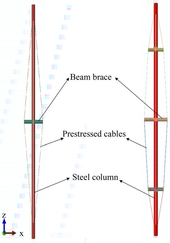
Figure 1.
Traditional prestressed column diagram.
Various scholars have explored the parameter optimization of beam-brace prestressed columns [15]. Ma et al. [16] proposed a novel approach for optimizing prestressed column parameters that are capable of addressing multi-objective optimization challenges. Wang et al. [17] suggested an optimization strategy for identifying the optimal transverse brace dimensions in prestressed steel columns, including defect sensitivity analysis with significant implications for prestressed column parameter optimization. Chen et al. [18] introduced an optimization method based on self-stress and integral self-stress states to determine the optimal prestressing force, allowing for the precise calculation of the ideal feasible prestress. The current parameter optimization efforts for prestressed columns primarily focus on traditional designs, leaving room for further research on new prestressed column designs.
Currently, several researchers are examining the monitoring and intelligent assessment of conventional prestressed strut columns [19]. Liu et al. [20] devised an intelligent evaluation technique for prestressed steel columns using the digital twin (DT) technology, encompassing performance analysis and maintenance. Zhu et al. [21] proposed an intelligent prediction method for the construction and safety of prestressed columns based on the DT technology, laying a methodological foundation for safety forecasting. Liu et al. [22] conducted intelligent evaluations of prestressed cable safety through DT and artificial intelligence integration, offering a methodology for the intelligent evaluation and application of prestressed cables. Shen et al. [23] developed a health monitoring technology for prestressed strut columns, considering erosion impacts and demonstrating high accuracy. Wu et al. [24] analyzed the buckling behavior of prestressed strut columns using machine learning and enabling an intelligent assessment of the structure’s nonlinear behavior. Currently, evaluations predominantly concentrate on traditional prestressed columns, with the analysis and assessment of new prestressed column types warrant further exploration.
In summary, extensive research has been conducted on beam-brace prestressed columns. The bearing capacity of the traditional prestressed column is generally improved by increasing the number of transverse braces. However, studies on augmenting end constraints through additional end plates and improving directionality by altering the force form of the cables are limited. This study explores the elastoplastic stable bearing capacity of the novel dual-steering-plate-brace prestressed column and optimizes its parameters.
2. Calculation Model
This study investigates the elastoplastic stable bearing capacity of three types of prestressed columns using the finite element software ANSYS 15.0. It also optimizes the prestressed value, steering plate position, and size. The model considers nonlinear contact and geometric defects, calculating the elastic–plastic stability-bearing capacity of the new structure.
2.1. Assumptions
- (1).
- The steel columns and transverse beam braces are simplified into beam 188 elements, with the effects of large deformation considered.
- (2).
- Prestressed cables are simplified to Link10 elements, considering only the influence of tensile stress.
- (3).
- The separable motion contact algorithm is employed for the contact between the cable and the plate brace.
- (4).
- A rigid connection is utilized between the steel column and the support brace.
2.2. Initial Prestress
The relationship between the prestressed value and the elastoplastic stable bearing capacity is presented as follows [25]:
where and are the minimum and maximum prestress values; and are the minimum and maximum critical buckling loads.
The optimal prestress can be expressed as follows:
where is the optimum prestress value; and are the coefficients of correlation between the cable and the brace; is the elastoplastic stable bearing capacity of the prestressed column.
2.3. Nonlinear Analysis Methods
The Riks method was adopted in this study due to the highly nonlinear elastic stable bearing capacity calculation. The Risk method is a generalized displacement control method. It can solve nonlinear problems by constraining the load level and displacement vector simultaneously. When the initial arc length radius is set, is determined using the convergence rate below [26]:
where is the arc length radius; is the expected convergence iteration number of the load step; and is the number of iterations of the previous load step.
The iterative steps of tangential displacement are as follows:
where is the external reference force; is the stiffness matrix; is the tangent displacement; and is the load increment step.
2.4. Line-Surface Contact Algorithm
“Hard contact” is adopted in line and with surface contact [27]:
No contact
Contact
where is the pressure; is the gap.
2.5. Calculation Model
The geometric parameters of the three prestressed columns are listed in Table 1. The total height of the three types of prestressed columns is 3000 mm. The transverse braces are set up in the middle position. The length H of the middle transverse brace is 300 mm. The latter two prestressed columns are symmetrically arranged with a second transverse brace. The steel column diameter (D) is 50 mm. The geometric model is depicted in Figure 2, where Figure 2a illustrates the model of a single-beam-brace column, Figure 2b shows the three-beam-brace column, and Figure 2c displays the model of the new dual-steering-plate-brace column.

Table 1.
Prestressed column section parameters.
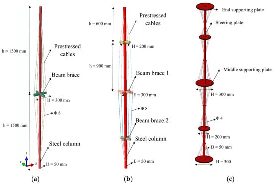
Figure 2.
Geometric model. (a) Single-beam-brace column (b) Three-beam-brace column (c) Dual-steering-plate-brace column.
The calculation model’s material is Q235 steel, with a yield strength of 235 MPa. The strain value at the yield platform’s end is 0.025, the ultimate strain is 0.26, the elastic modulus is 210 GPa, Poisson’s ratio is 0.3, and the steel column’s diameter is 50 mm. The mesh model is exhibited in Figure 3. The column was analyzed using beam 188 elements, while Solid 185 elements were employed for the plate, and Link 10 elements for the prestressed cable. The prestressed cables and plates are interconnected by sliding to prevent damage. Geometric defects are applied by means of displacement according to the first-order modes.
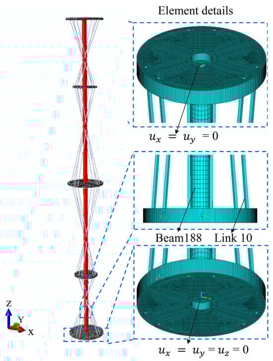
Figure 3.
Mesh model.
The end supporting plate at the bottom is a fixed constraint in this study. The top-end supporting plate is constrained in the x and y directions, with the load applied in the z direction. The analysis of elastoplastic stable bearing capacity comprises the following three loading steps: the initial step involves static analysis, boundary conditions application, and prestress. The second step encompasses modal analysis. The third step includes applying geometric initial defects and conducting elastoplastic stability load analysis. The arc length method is applied for solving, and the value of the load during calculation requires multiple trial calculations. The maximum convergence time of the final calculated sub-steps approaches 1 s to ensure the high accuracy of the results.
3. Results and Discussion
3.1. Elastoplastic Stable Bearing Capacity Analysis
3.1.1. Plastic Deformation Stress Nephogram
The modal buckling solutions described in Section 2.5 are shown in Figure 4. The modes of bearing columns are different under different prestressing directions.
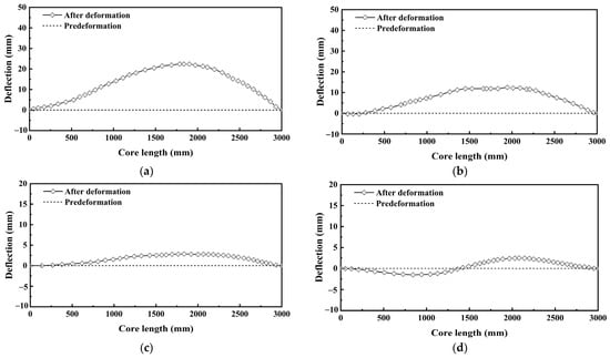
Figure 4.
Modal buckling solution. (a) Single-beam-brace column. (b) Three-beam-brace column. (c) Three-beam-brace column. (d) Dual-steering-plate-brace column.
Figure 5 presents the deformation cloud diagram of the four steel columns under the maximum load. Figure 5a is the non-prestressed column, Figure 5b is the single-beam-brace column, Figure 5c is the three-beam-brace column, and Figure 5d is the dual-steering-plate-brace column. The examination of the nephogram reveals that the deflection of the four models under maximum load is similar. The deformation forms of traditional prestressed columns are identical. However, the deformation form of the dual-steering-plate-brace column differs from the first three, indicating that the double-steering braces alter the force form of the column, thereby changing its nonlinear buckling form.
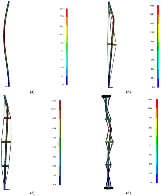
Figure 5.
Plastic deformation stress nephogram. (a) Non-prestressed column. (b) Single-beam-brace column. (c) Three -beam-brace column. (d) Dual-steering-plate-brace column.
3.1.2. Relation between Axial Load and Mid Deflection
The influence of different initial defects on the bearing capacity of the new prestressed column is shown in Figure 6a. It can be seen from the calculated results that the bearing capacity is related to the initial defect value. The larger the initial defect value is, the lower the bearing capacity value. The first mode is selected as the initial defect for all kinds of columns in this paper. The relationship curves between the axial load and mid-span deflection obtained through the numerical calculation of an ordinary column and three types of prestressed columns are shown in Table 2 and Figure 6b. All prestressed columns are subjected to a prestressed value of 15 kN. The vertical load is incrementally increased in units of 5 mm of displacement, and the deflection varies across different models. The results demonstrate that both the ordinary column and the three types of prestressed columns become unstable at extreme points, with the increase in the vertical force being proportional to the mid-span displacement value of the column. When the vertical force is minimal, the mid-span displacement value of the column remains small.
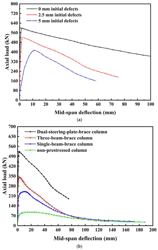
Figure 6.
Load deflection curve. (a) Different initial defects. (b) Four types of columns.
Table 2.
Axial load-deflection table.
When lateral deformation occurs, the cable exerts prestress on the central column by applying force to the transverse brace, constraining the mid-span, and resisting its deformation. The deformation’s limit value correlates to some extent with the prestress value. Under axial load, an additional bending moment is generated on the bearing column undergoing lateral deformation, exacerbating the deformation, a phenomenon known as the second-order effect. The second-order effect exerts the least influence on the dual-steering-plate-brace column, while, for ordinary columns without prestress constraints, its impact is the most significant.
As the vertical load increases, exceeding the ultimate load leads to plastic deformation, which persists until failure. In the later loading stages, among the four models of the bearing column, the prestressed column with double-steering plates shows the least deflection, indicating that the ductility of the prestressed column is inferior to that of the non-prestressed column and traditional prestressed columns.
It can be seen from the data that the stable ultimate bearing capacity of the non-prestressed column is 95.8 kN, whereas those of the three types of prestressed columns are 239, 342, and 518 kN, respectively. These results demonstrate that the bearing capacities of prestressed columns are 2.49–5.41 times higher than those of the non-prestressed columns, underscoring the significant role of prestressed cables in enhancing the stability of the ultimate bearing capacity.
The calculated elastic–plastic stability capacity at large deflection is Pu, the deflection at instability is δu, the maximum deflection at failure is δd, and the equivalent plastic strain of the cross-section of the central column at failure is εeq [28]. The stability coefficient φ is defined as follows [29,30]:
where Pcr is the linear elastic bearing capacity calculated by the Euler formula.
φ = Pu/Pcr
Four kinds of pressure columns are analyzed in this section as follows: the non-prestressed column (c-1), single-beam-brace column (c-2), three-beam-brace column (c-3), and dual-steering-plate-brace column (c-4). The comparisons between the linear and nonlinear bearing capacity of bearing columns are shown in Figure 7. The initial defect has the greatest effect on the non-prestressed column at 31.6% from the reduction rate of bearing capacity. Prestress is of great help in reducing the initial defect effect, with the lowest reduction rate of 10.49% for the single-beam-brace column.
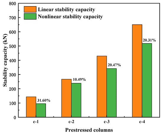
Figure 7.
Comparison of linear and nonlinear bearing capacity.
The comparisons of the elastic and plastic deformation capacity of four kinds of pressure columns (c-1, c-2, c-3, and c-4) are shown in Figure 8. It can be seen that the proportion of elastic deformation in the non-prestressed column is the highest at 11.91%, while the proportion in the three-beam-brace column is the lowest at 2.02%, from the ratio of elastic deformation to plastic deformation. As the number of transverse braces increases, the stiffness and the bearing capacity of the prestressed column also increase, but the proportion of elastic deformation decreases. The improvement in the bearing capacity of prestressed columns comes at the cost of sacrificing a portion of elastic deformation.
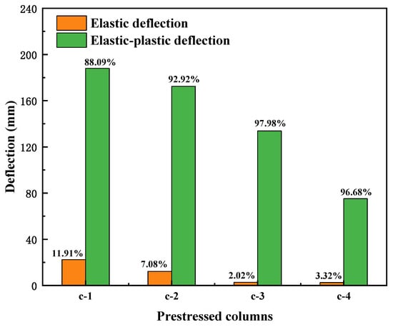
Figure 8.
Comparison of elastic and plastic deformation.
The plastic calculation results of the bearing columns are shown in Table 3. The values of the maximum equivalent stress of the section, as obtained using the four models, are similar. However, the variations in the maximum equivalent plastic strain and the deflections at which instability and failure occur in these models contrast with the changes in the ultimate bearing capacity. This indicates that the increased bearing capacity of prestressed columns comes at the expense of reduced plasticity and ductility properties.
Table 3.
Plastic calculation results of bearing columns.
3.2. Parameter Optimization Analysis
3.2.1. Effect of Prestress Value
The buckling load variation in the prestressed columns under different prestress values is shown in Figure 9. The range of prestress values considered spans from 0 to 100 kN. It can be seen from the calculation that the optimal prestress value of the single-beam-brace column is 14.9 kN, the optimum prestress value of the three-beam-brace column is 14.7 kN, and the optimal prestress value of the dual-steering-plate-brace column is 14.3 kN. The prestressed value adopted in this paper is 15 kN. As the prestress value increases from 5 to 15 kN, the buckling loads of the three prestressed columns escalate rapidly. The load-bearing capacity of the dual-steering-plate-brace column increases by 4.6 times, the three-beam-brace column increases by 2.97 times, and the single-beam-brace column increases by 1.84 times. In the range of 15 to 45 kN, the buckling loads stabilize, remaining essentially unchanged. Beyond 45 kN, the buckling load value begins a gradual decline. At 100 kN, despite the prestress value tripling, the buckling load values are reduced significantly.
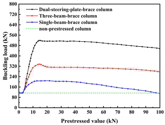
Figure 9.
Effect of prestress value.
3.2.2. Effect of Steering Plate Position
This study also analyzes the effect of the steering plate position on buckling load variation. The central column has a total height of 3000 mm, with the middle support plate positioned at 1500 mm. The distances between the steering plates and the ends change symmetrically, ranging from 50 to 1450 mm.
The results demonstrate a distinct pattern in how the steering plate position influences the buckling load values, suggesting the existence of an optimal buckling load value (Figure 10). At a steering plate height of 750 mm, the buckling load value peaks at 518 kN. As the height of the steering plate progressively decreases from 750 to 50 mm, the maximum buckling load value significantly drops. At 50 mm, it reduces to 239 kN, which is a decrease of nearly half. Conversely, as the steering wheel height increases from 750 to 1450 mm, the maximum buckling load diminishes to 208 kN, which is 310 kN below the optimal maximum value. The rules of the three-beam-brace column are consistent. However, the maximum buckling load is 66% of the new prestressed column.
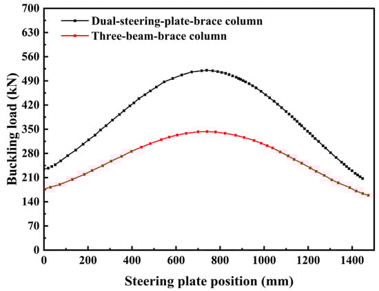
Figure 10.
Effect of steering plate position.
3.2.3. Effect of Steering Plate Size
In this section, the prestressed columns constrained by a 15 kN prestress and with a lower steering plate height of 1500 mm are examined. This study investigates the buckling load variation pattern by altering the steering plate radius from 50 to 130 mm (Figure 11). The findings revealed that the steering plate size markedly affects the buckling load of the prestressed columns. With a steering plate radius of 50 mm, the buckling load is 245 kN. As the steering plate size enlarges, the buckling load increases, exhibiting a linear variation pattern. Upon reaching a radius of 115 mm, the buckling load peaks at 518 kN and then begins to stabilize. Between the radii of 115 and 130 mm, the buckling load value incrementally rises. At 130 mm, the buckling load attains 530 kN, a mere increase of 12 kN compared to the 115 mm radius, which also impacts structural aesthetics. The rules of the three-beam-brace column are consistent. However, the maximum buckling load is 66% of the new prestressed column. These findings indicated a clear correlation between the steering plate size and the buckling load value. When designing the steering plate size, this correlation can be effectively leveraged to select an optimal size based on these insights.
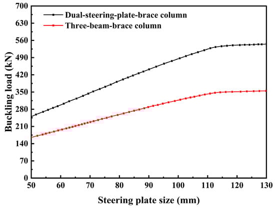
Figure 11.
Effect of steering plate size.
The results indicate that various structural parameters, such as the magnitude of the prestressing force, the distribution of the steering plate position, and the dimensions of the steering plate, significantly influence the load-bearing capacity of the dual steering brace column. When the prestress is minimal, the bearing capacity rapidly escalates to the optimal value and then gradually diminishes. The influence of the steering plate’s position on the buckling load value demonstrates a discernible pattern, with an optimal value existing. At the midpoint position of the steering disc, the buckling load attains its maximal value. The impact of the steering plate’s size is examined. With a small steering plate, the buckling load value exhibits a linear increase. Once the steering plate attains a certain dimension, the buckling load value stabilizes and remains consistent. The optimization analysis in this study provides guidance for refining the design of prestressed columns. For already-designed prestressed columns, alterations in the prestressed construction process, prestressed value, and structural parameters should not be arbitrary.
4. Conclusions
This study analyzes the elastoplastic stable bearing capacity of a novel prestressed column and compares the outcomes with those of traditional prestressed columns. The parameter optimization analysis for the prestressed value, the steering plate position, and the steering plate size is conducted. The findings reveal that the new prestressed column exhibits superior material utilization. The results are as follows:
- (1)
- The elastic stable bearing capacity of four types of pressure-bearing columns is analyzed. Owing to the rationality of the end constraints and the prestressed arrangement, the new type of prestressed column exhibits a 5.41-fold increase compared to ordinary non-prestressed columns. In contrast, traditional prestressed columns with identical parameters show only a 2.49–3.55-fold increase, underscoring the more reasonable stress distribution in the new type of prestressed column.
- (2)
- With relatively small prestress (<15 kN), the bearing capacity swiftly reaches its optimal value. The buckling load remains stable at between 15 and 45 kN of the prestressed value. Beyond 45 kN, the buckling load value gradually declines. At a prestressed value of 120 kN, the value nearly triples, while the buckling load value decreases by approximately 15.3%.
- (3)
- The steering plate’s position markedly influences the bearing capacity, with an optimal value observed. At a 750 mm height, the buckling load value peaks; as the steering plate’s height decreases from 750 to 50 mm, the maximum buckling load significantly diminishes. A reduction of 50 mm in the steering plate’s height results in a nearly twofold decrease in the buckling load.
- (4)
- The steering plate’s size profoundly affects the buckling load value of the dual steering brace column. With a 50 mm radius, the buckling load value is 245 kN. As the steering plate’s size increases, the buckling load value escalates, displaying a linear trend. When the distance between the center column and the steering hole reaches 115 mm, the buckling load value attains 518 kN and begins to stabilize. These research findings provide a theoretical foundation for the practical engineering application of a new type of prestressed column.
Author Contributions
Y.L.: Methodology, Writing the original draft, and Resources. B.L.: Visualization, Investigation, and Methodology. X.Y.: Investigation, Writing, Reviewing, and Editing. Z.H.: Methodology. Z.L.: Investigation. All authors have read and agreed to the published version of the manuscript.
Funding
This research was funded by the National Natural Science Foundation of China [Grant No. 51178205] and the Young Elite Scientists Sponsorship Program by CAST [Grant No. 2021QNRC001]. And the APC was funded by [Grant No. 2021QNRC001].
Data Availability Statement
The data generated are available in the article.
Conflicts of Interest
The authors declare no conflict of interest.
References
- Suzuki, Y.; Lignos, D. Experimental evaluation of steel columns under seismic hazard-consistent collapse loading protocols. J. Struct. Eng. 2021, 147, 04021020. [Google Scholar] [CrossRef]
- Klasson, A.; Crocetti, R.; Hansson, E.F. Slender steel columns: How they are affected by imperfections and bracing stiffness. Structures 2016, 8, 35–43. [Google Scholar] [CrossRef]
- Harries, K.A.; Peck, A.J.; Abraham, E. Enhancing stability of structural steel sections using frp. Thin-Walled Struct. 2009, 47, 1092–1101. [Google Scholar] [CrossRef]
- Saito, D.; Wadee, M.A. Post-buckling behaviour of prestressed steel stayed columns. Eng. Struct. 2008, 30, 1224–1239. [Google Scholar] [CrossRef]
- Ma, T.; Liu, X.; Hu, Y.; Chung, K.; Li, G. Structural behaviour of slender columns of high strength s690 steel welded h-sections under compression. Eng. Struct. 2018, 157, 75–85. [Google Scholar] [CrossRef]
- Kim, M.; Mehdi, A.I.; Hayat, U. Spatial stability of pre-stressed mono-symmetric steel beams with un-bonded/bonded deviators under compression and end moments. J. Constr. Steel Res. 2022, 189, 107078. [Google Scholar] [CrossRef]
- Li, G.; Chen, B.; Zhu, B.; Yang, Z.; Ge, H.; Liu, Y. Axially loaded square concrete-filled steel tubular long columns made of high-strength materials: Experimental investigation, analytical behavior and design. J. Build. Eng. 2022, 58, 104994. [Google Scholar] [CrossRef]
- Kambal, M.E.M.; Jia, Y. Theoretical and experimental study on flexural behavior of prestressed steel plate girders. J. Constr. Steel Res. 2018, 142, 5–16. [Google Scholar] [CrossRef]
- Smith, R.J.; McCaffrey, G.T.; Ellis, J.S. Buckling of a single-crossarm stayed column. J. Struct. Div. 1975, 101, 219–235. [Google Scholar] [CrossRef]
- Temple, M. Buckling of stayed columns. J. Struct. Div. 1977, 103, 839–851. [Google Scholar] [CrossRef]
- Osofero, A.I.; Wadee, M.A.; Gardner, L. Experimental study of critical and post-buckling behaviour of prestressed stayed columns. J. Constr. Steel Res. 2012, 79, 226–241. [Google Scholar] [CrossRef]
- Martins, J.P.; Shahbazian, A.; Simões da Silva, L.; Rebelo, C.; Simões, R. Structural behaviour of prestressed stayed columns with single and double cross-arms using normal and high strength steel. Arch. Civ. Mech. Eng. 2016, 16, 618–633. [Google Scholar] [CrossRef]
- Wadee, M.A.; Gardner, L.; Hunt, T. Buckling mode interaction in prestressed stayed columns. Proc. Inst. Civ. Eng. Struct. Build. 2013, 166, 403–412. [Google Scholar] [CrossRef]
- Li, Y.; Li, B.; Yin, X.; Han, Z. Buckling analysis of a new type of double-steering prestressed plate column. Buildings 2023, 13, 2574. [Google Scholar] [CrossRef]
- Liang, Q.Q.; Xie, Y.M.; Steven, G.P. Generating optimal strut-and-tie models in prestressed concrete beams by performance-based optimization. ACI Struct. J. 2001, 98, 226–232. [Google Scholar]
- Ma, Q.; Ohsaki, M.; Chen, Z.; Yan, X. Multi-objective optimization for prestress design of cable-strut structures. Int. J. Solids Struct. 2019, 165, 137–147. [Google Scholar] [CrossRef]
- Wang, H.; Li, P.; Wu, M. Crossarm length optimization and post-buckling analysis of prestressed stayed steel columns. Thin-Walled Struct. 2019, 144, 106371. [Google Scholar] [CrossRef]
- Chen, Y.; Yan, J.; Sareh, P.; Feng, J. Feasible prestress modes for cable-strut structures with multiple self-stress states using particle swarm optimization. J. Comput. Civ. Eng. 2020, 34, 04020003. [Google Scholar] [CrossRef]
- Li, H.; Ren, L.; Jia, Z.; Yi, T.; Li, D. State-of-the-art in structural health monitoring of large and complex civil infrastructures. J. Civ. Struct. Health Monit. 2016, 6, 3–16. [Google Scholar] [CrossRef]
- Liu, Z.; Shi, G.; Jiao, Z.; Zhao, L. Intelligent safety assessment of prestressed steel structures based on digital twins. Symmetry 2021, 13, 1927. [Google Scholar] [CrossRef]
- Zhu, H.; Wang, Y. Intelligent prediction of prestressed steel structure construction safety based on bp neural network. Appl. Sci. 2022, 12, 1442. [Google Scholar] [CrossRef]
- Liu, Z.; Shi, G.; Zhang, A.; Huang, C. Intelligent tensioning method for prestressed cables based on digital twins and artificial intelligence. Sensors 2020, 20, 7006. [Google Scholar] [CrossRef] [PubMed]
- Shen, J.; Lapira, L.; Wadee, M.A.; Gardner, L.; Pirrera, A.; Groh, R.M. Probing in situ capacities of prestressed stayed columns: Towards a novel structural health monitoring technique. Philos. Trans. R. Soc. A 2023, 381, 20220033. [Google Scholar] [CrossRef] [PubMed]
- Wu, K.; Qiang, X.; Xing, Z.; Jiang, X. Buckling in prestressed stayed beam–columns and intelligent evaluation. Eng. Struct. 2022, 255, 113902. [Google Scholar] [CrossRef]
- Budd, C.; Hunt, G.; Kuske, R. Asymptotics of cellular buckling close to the maxwell load. Proc. R. Soc. Lond. Ser. A Math. Phys. Eng. Sci. 2001, 457, 2935–2964. [Google Scholar] [CrossRef]
- Orlando, D.; Gonçalves, P.; Rega, G.; Lenci, S. Nonlinear dynamics and sensitivity to imperfections in augusti’s model. J. Mech. Mater. Struct. 2011, 6, 1065–1078. [Google Scholar] [CrossRef][Green Version]
- Gilardi, G.; Sharf, I. Literature survey of contact dynamics modelling. Mech. Mach. Theory 2002, 37, 1213–1239. [Google Scholar] [CrossRef]
- Wadee, M.A.; Gardner, L.; Osofero, A. Design of prestressed stayed columns. J. Constr. Steel Res. 2013, 80, 287–298. [Google Scholar] [CrossRef]
- Wang, Y.C.; Ju, N.P.; Zhao, J.J.; Xiang, X.Q. Formation mechanism of landslide above the mined out area in gentle inclined coal beds. J. Eng. Geol. 2013, 21, 61–68. [Google Scholar]
- Zhao, J.J.; Ma, Y.T.; Lin, B.; Lan, Z.Y.; Shi, W.B. Geomechanical mode of mining landslides with gently counter-inclined bedding—A case study of Madaling landslide in Guizhou Province. Chin. J. Rock Mech. Eng. 2016, 35, 2217–2224. [Google Scholar]


Disclaimer/Publisher’s Note: The statements, opinions and data contained in all publications are solely those of the individual author(s) and contributor(s) and not of MDPI and/or the editor(s). MDPI and/or the editor(s) disclaim responsibility for any injury to people or property resulting from any ideas, methods, instructions or products referred to in the content. |
© 2023 by the authors. Licensee MDPI, Basel, Switzerland. This article is an open access article distributed under the terms and conditions of the Creative Commons Attribution (CC BY) license (https://creativecommons.org/licenses/by/4.0/).