
Vision-Based Guiding System for Autonomous Robotic Corner Cleaning of Window Frames


Abstract
:1. Introduction
2. Literature Review
2.1. Recent Advances in Window Frame Manufacturing
2.2. Vision-Guided Robots in Manufacturing
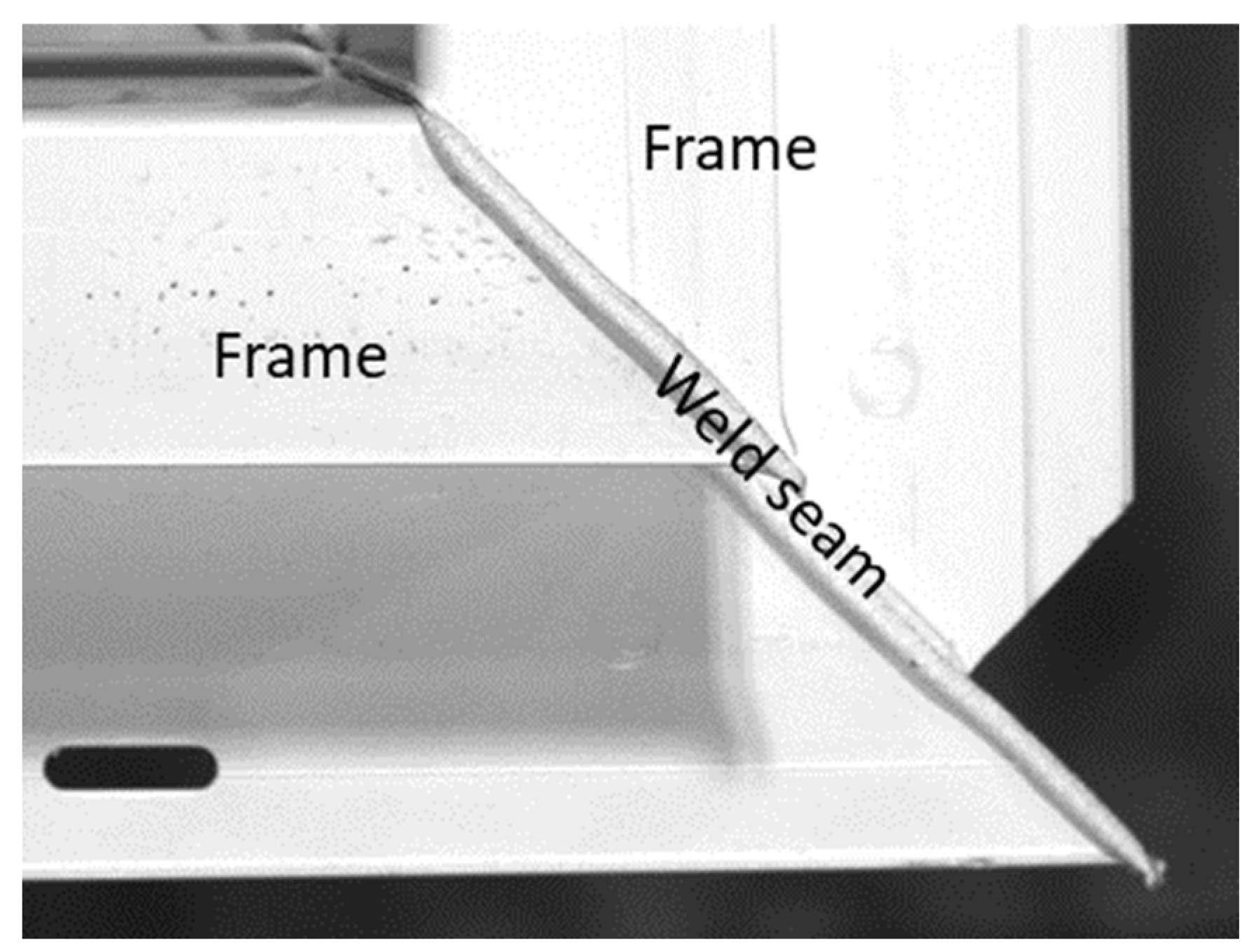
2.3. Weld Seam Detection
2.4. Summary and Research Gaps
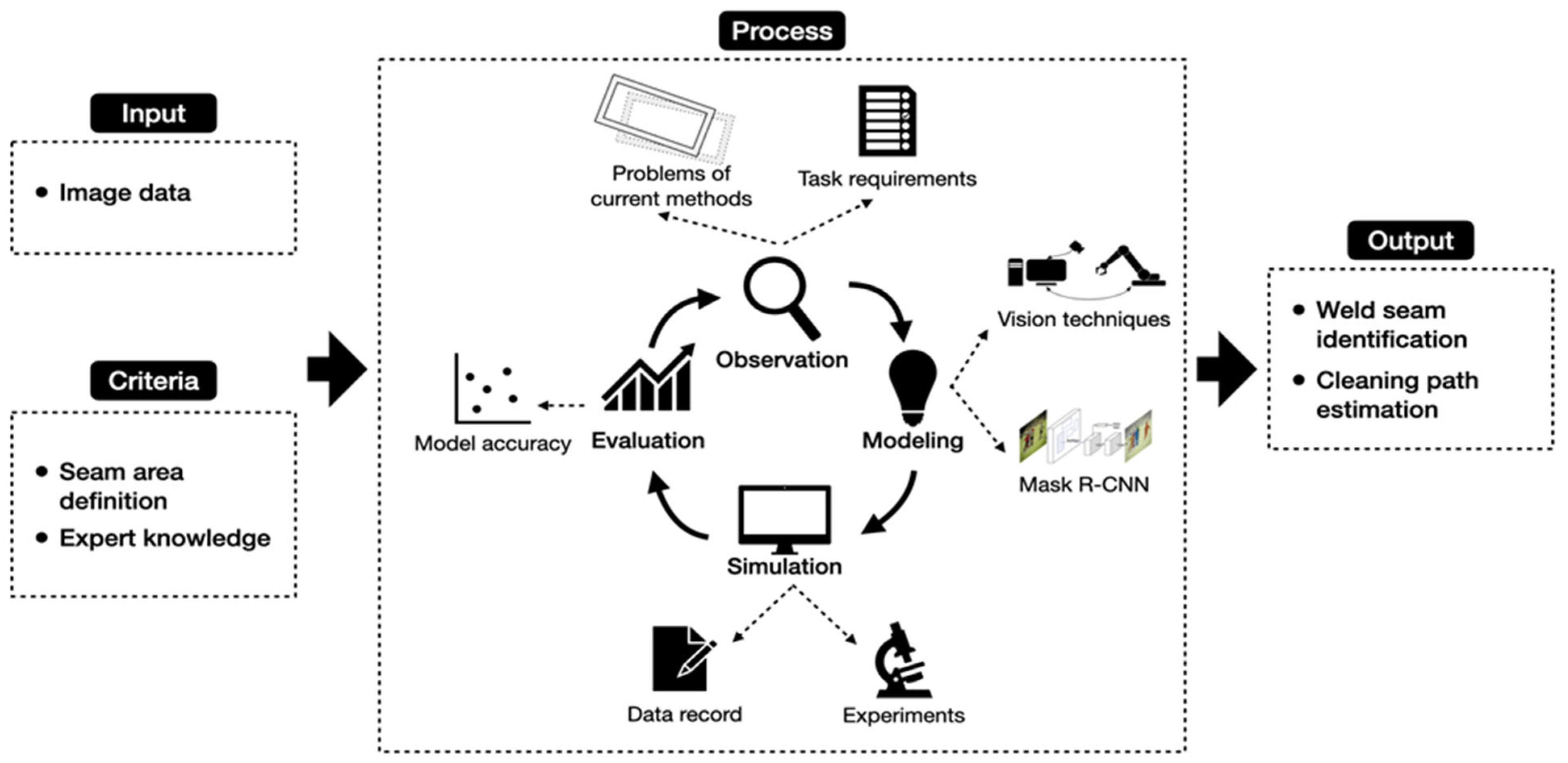
3. Methodology
4. Vision-Based Robotic Corner Cleaning of Window Frames
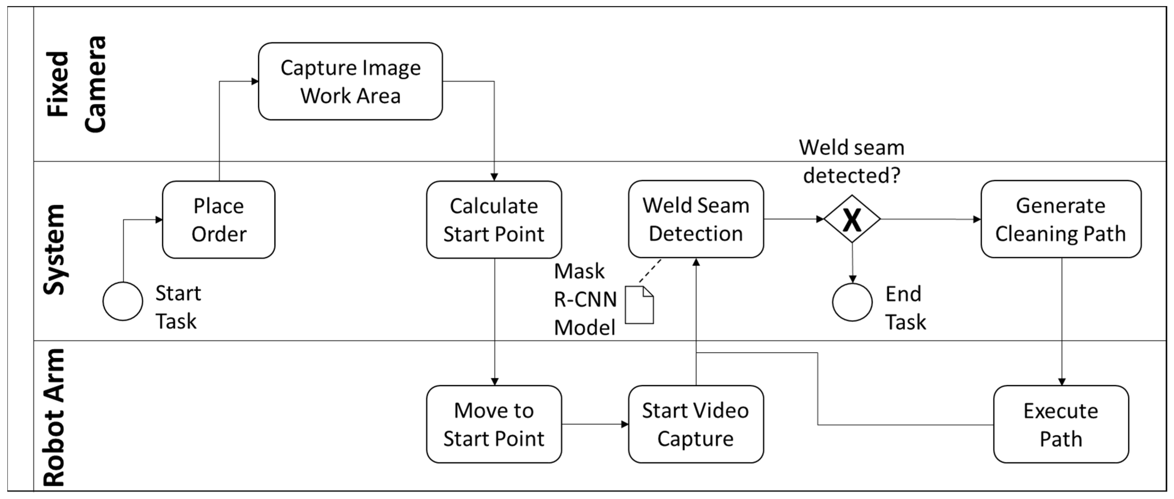
4.1. Proposed Framework
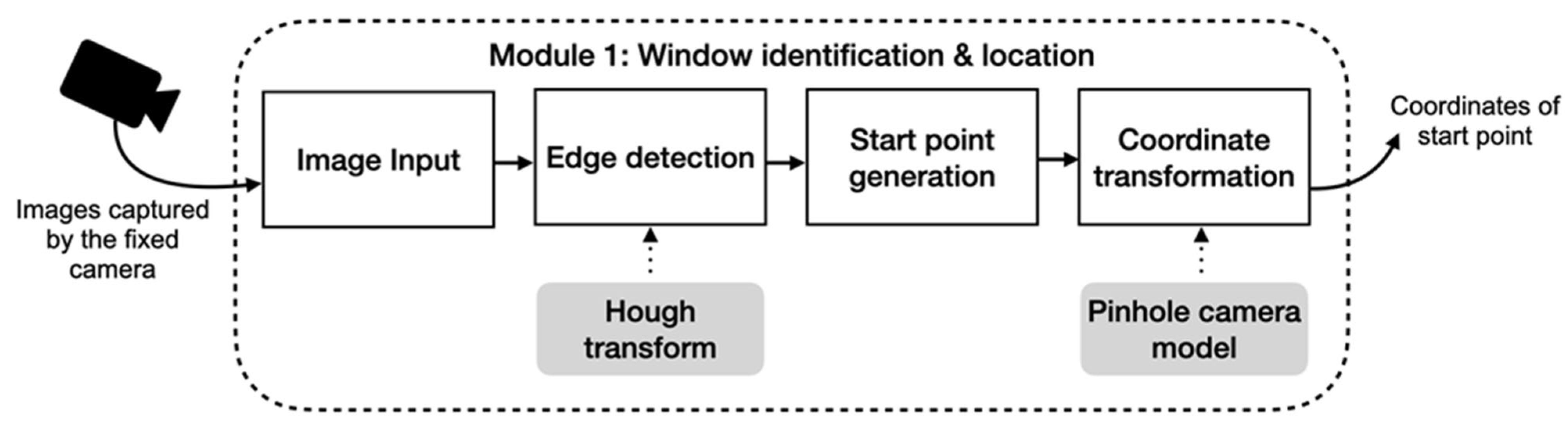
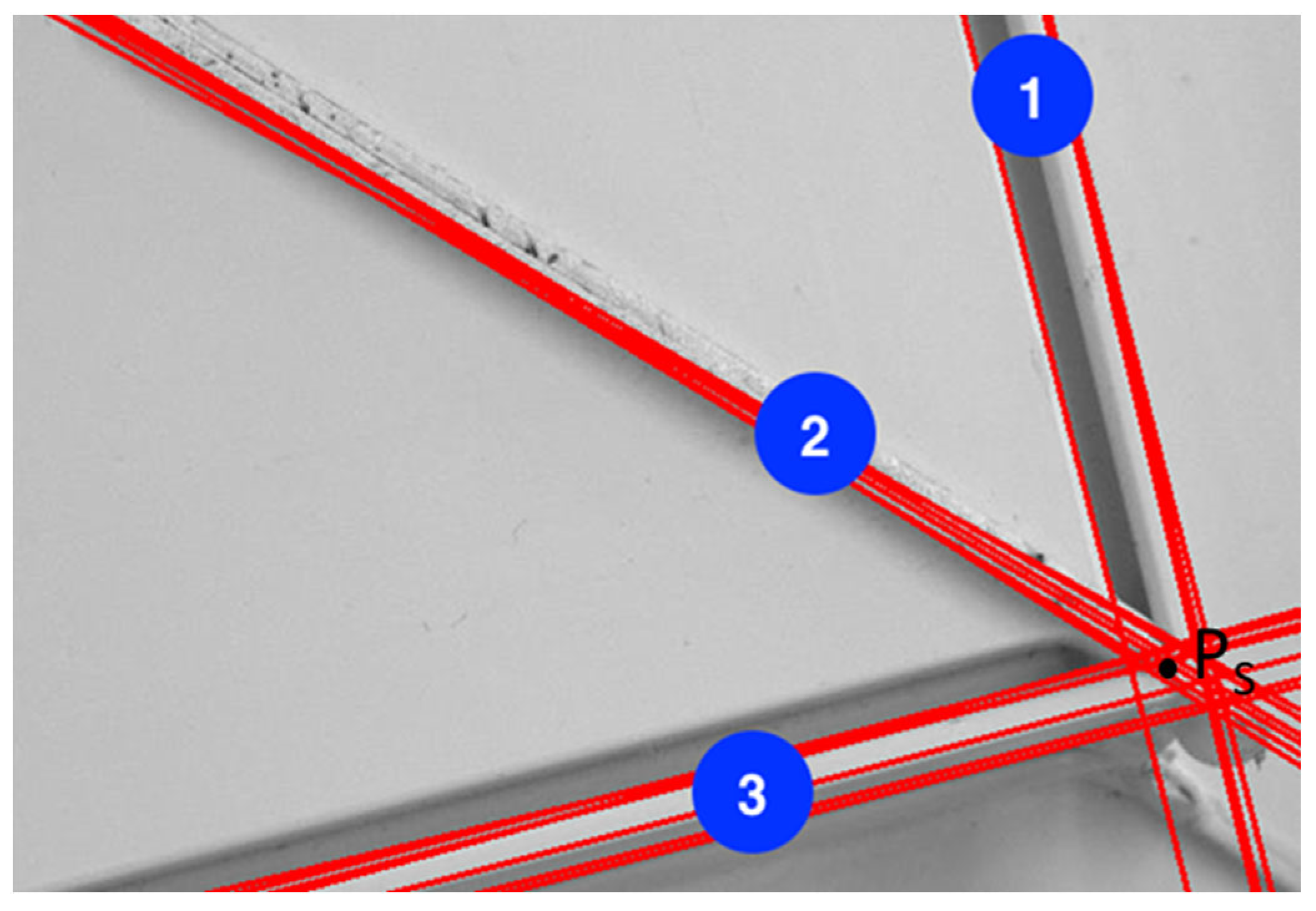
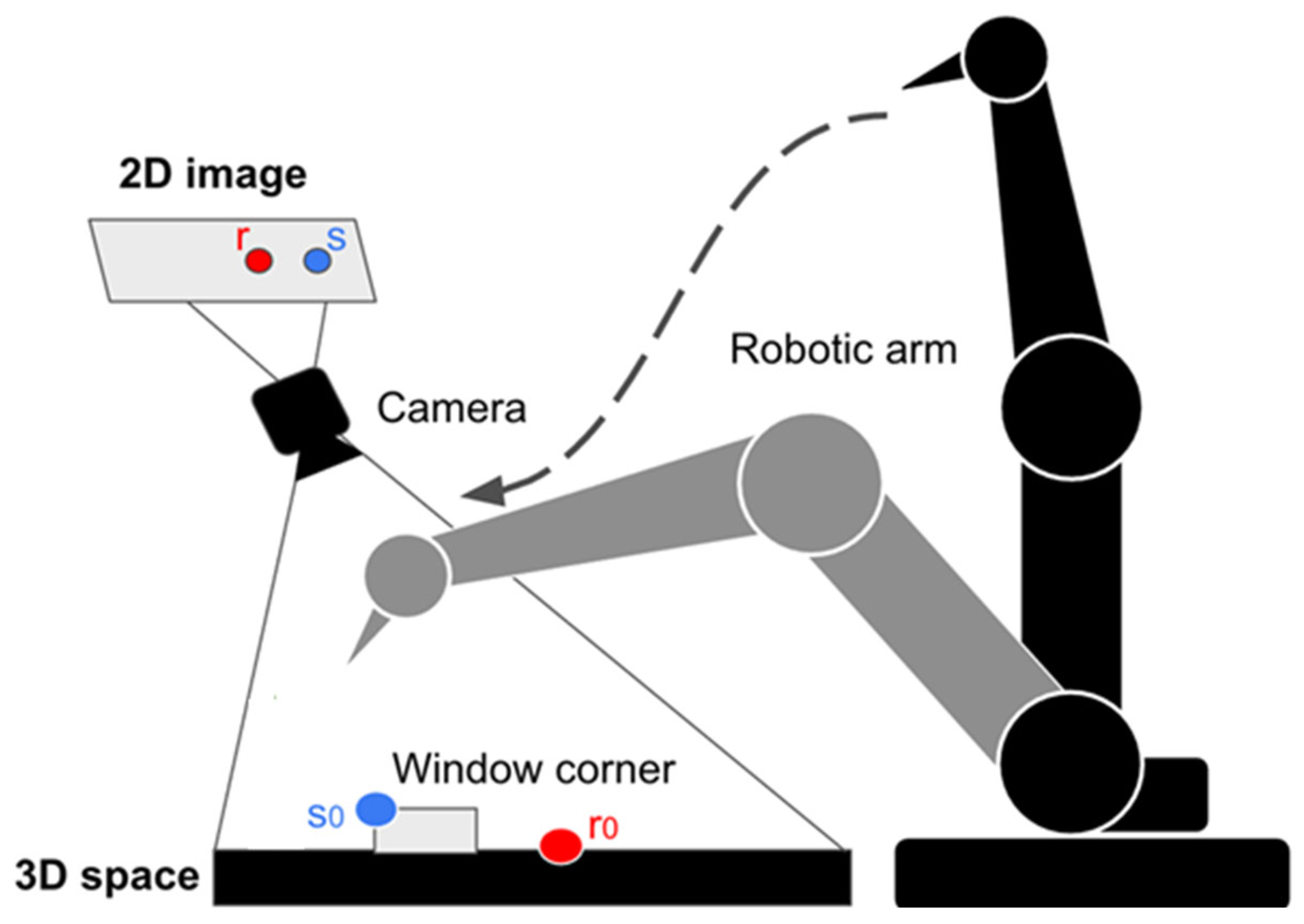
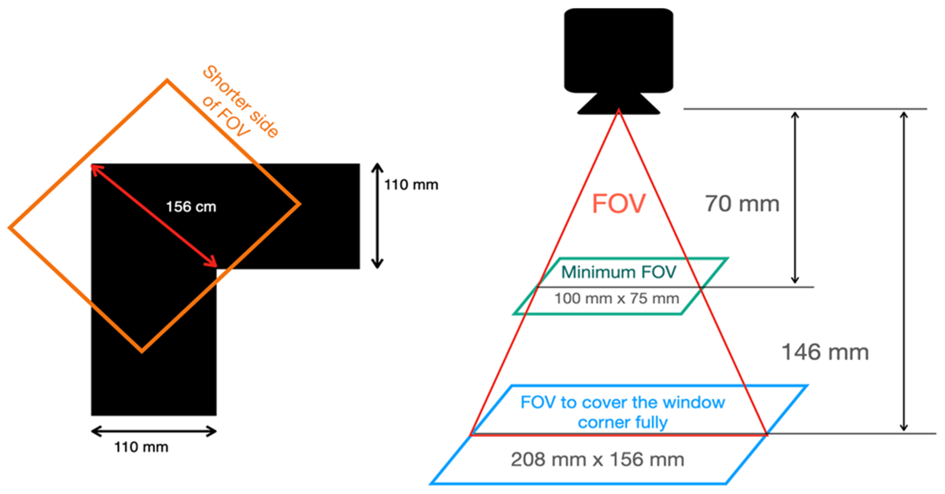
4.2. Module 1: Window Identification and Location
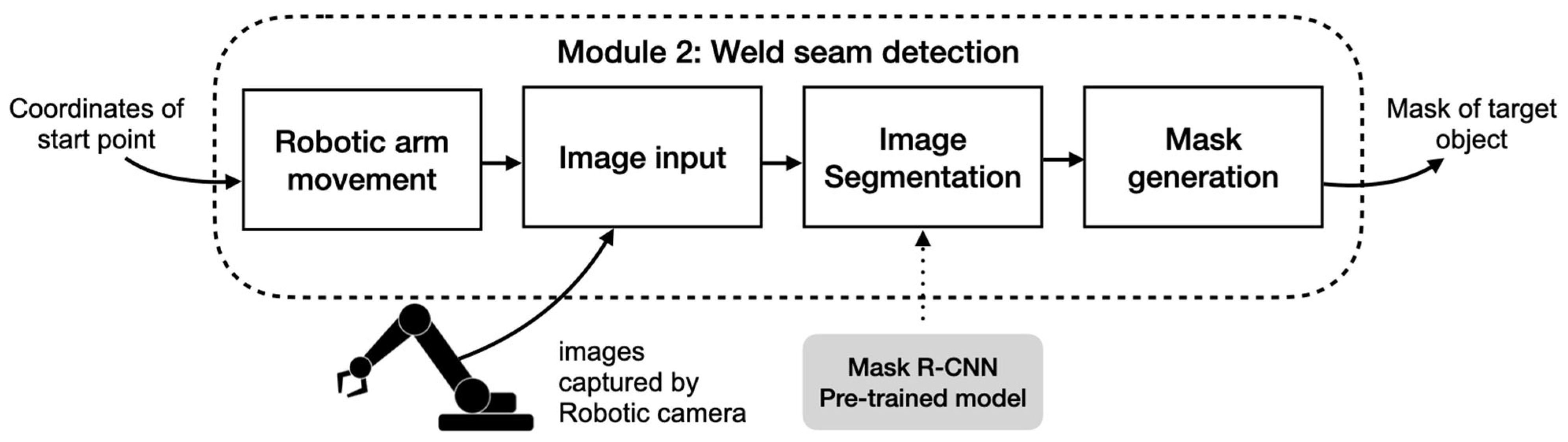
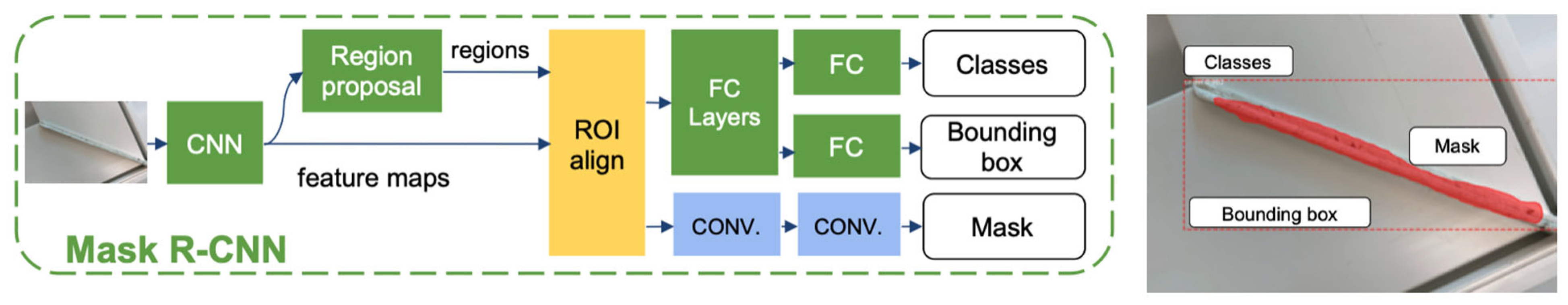
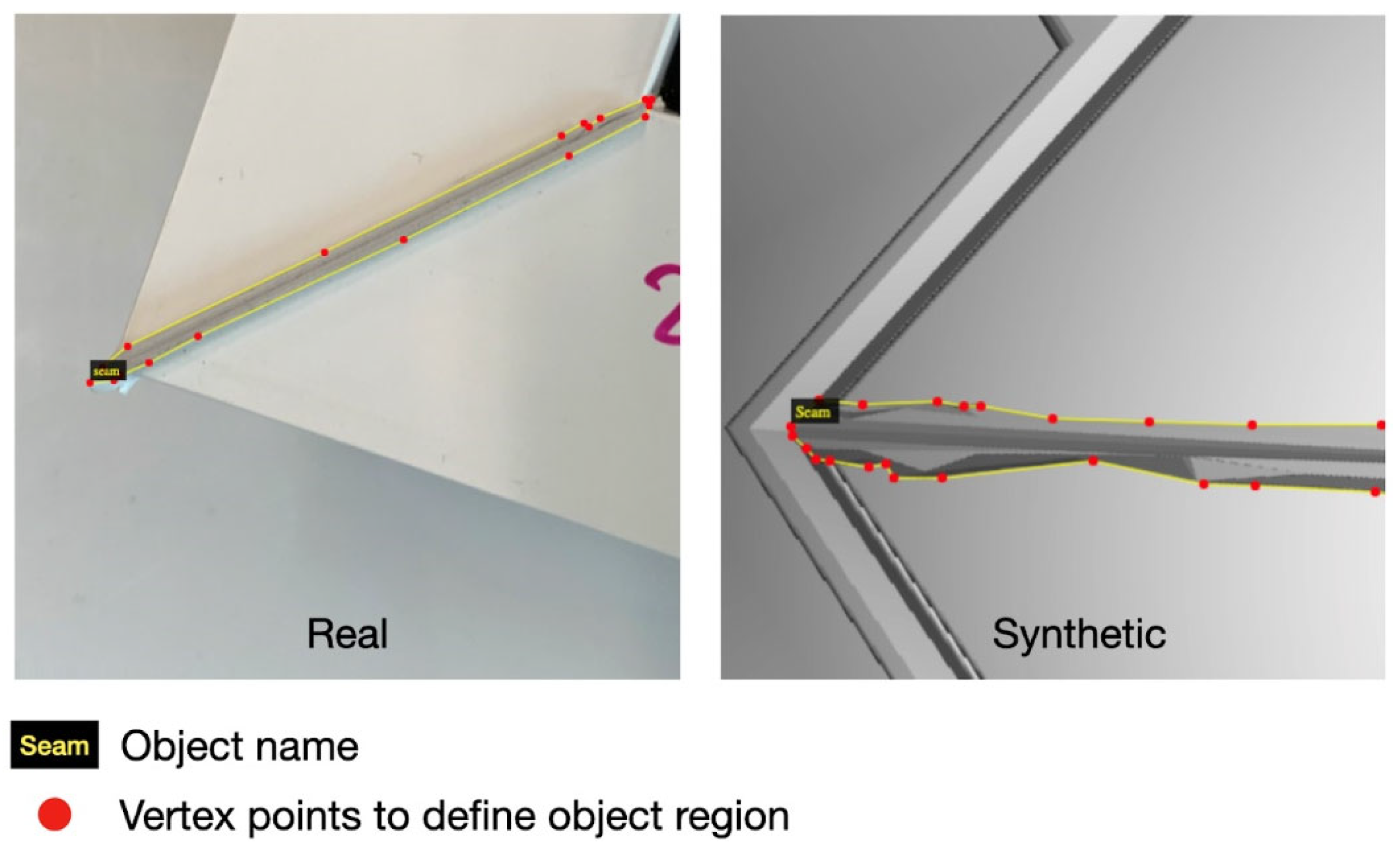
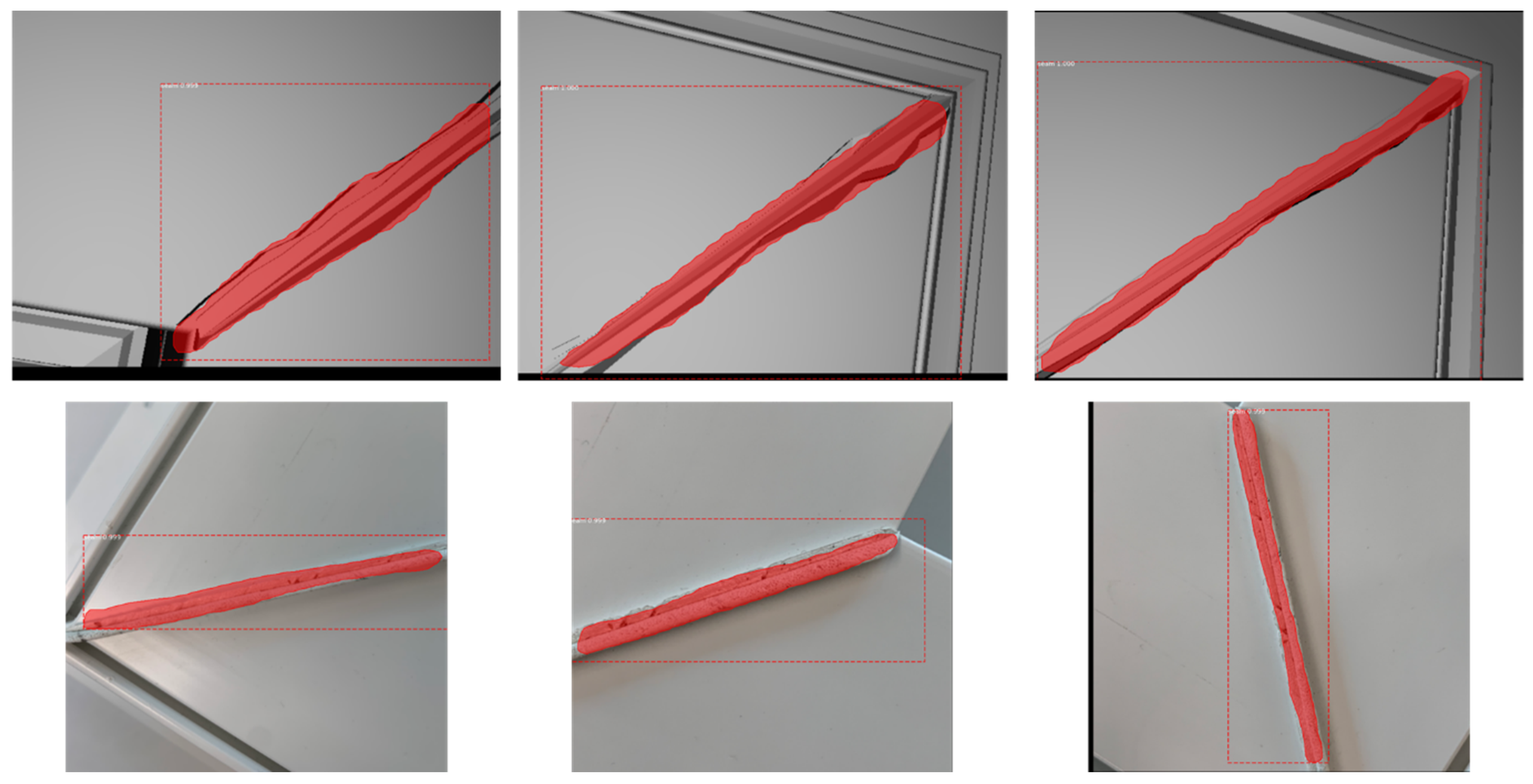
4.3. Module 2: Weld Seam Detection
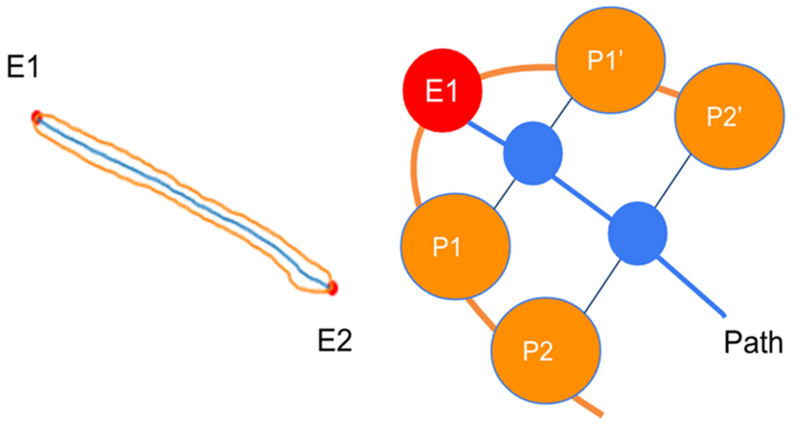
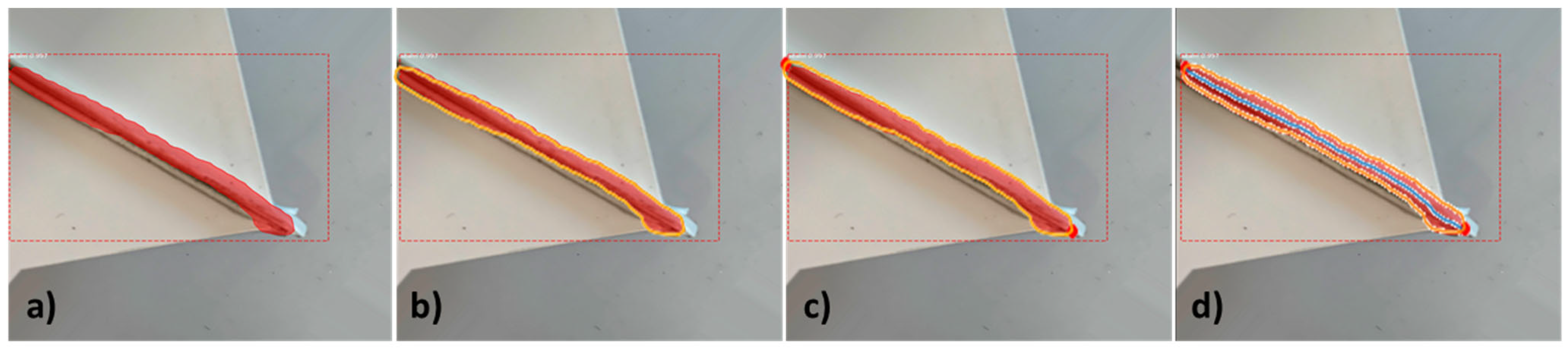
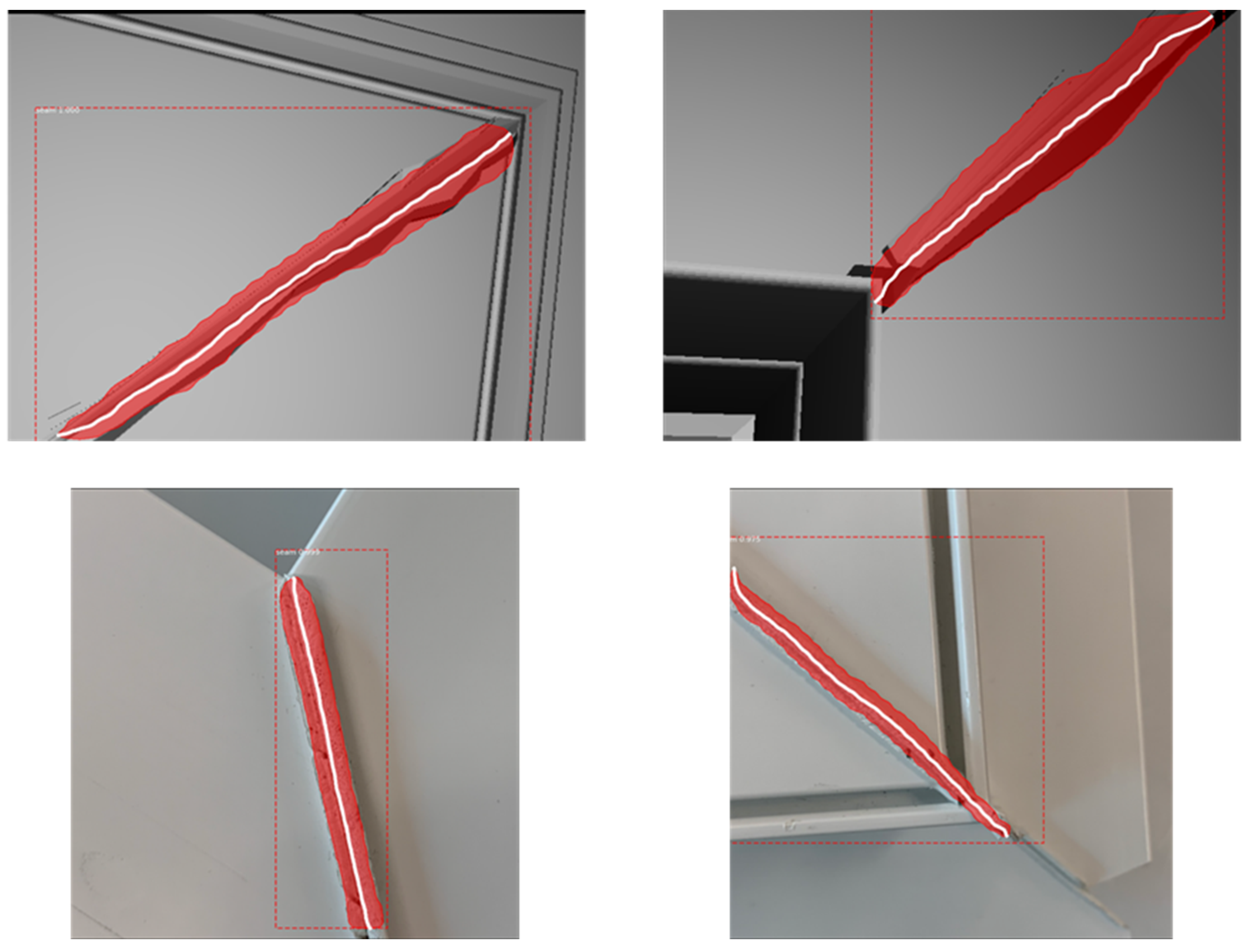
4.4. Module 3: Cleaning Path Generation
5. Results
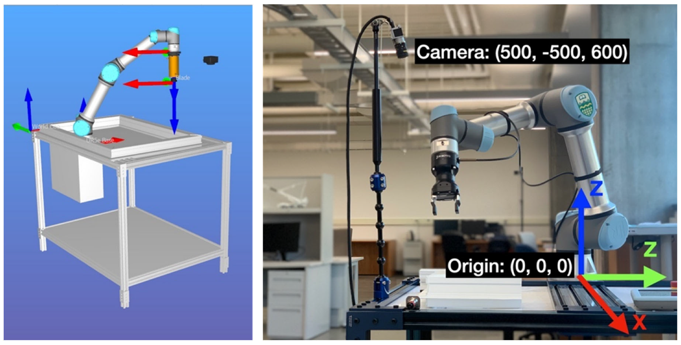
5.1. Experimental Setup
5.2. Framework Validation
5.2.1. Module 1
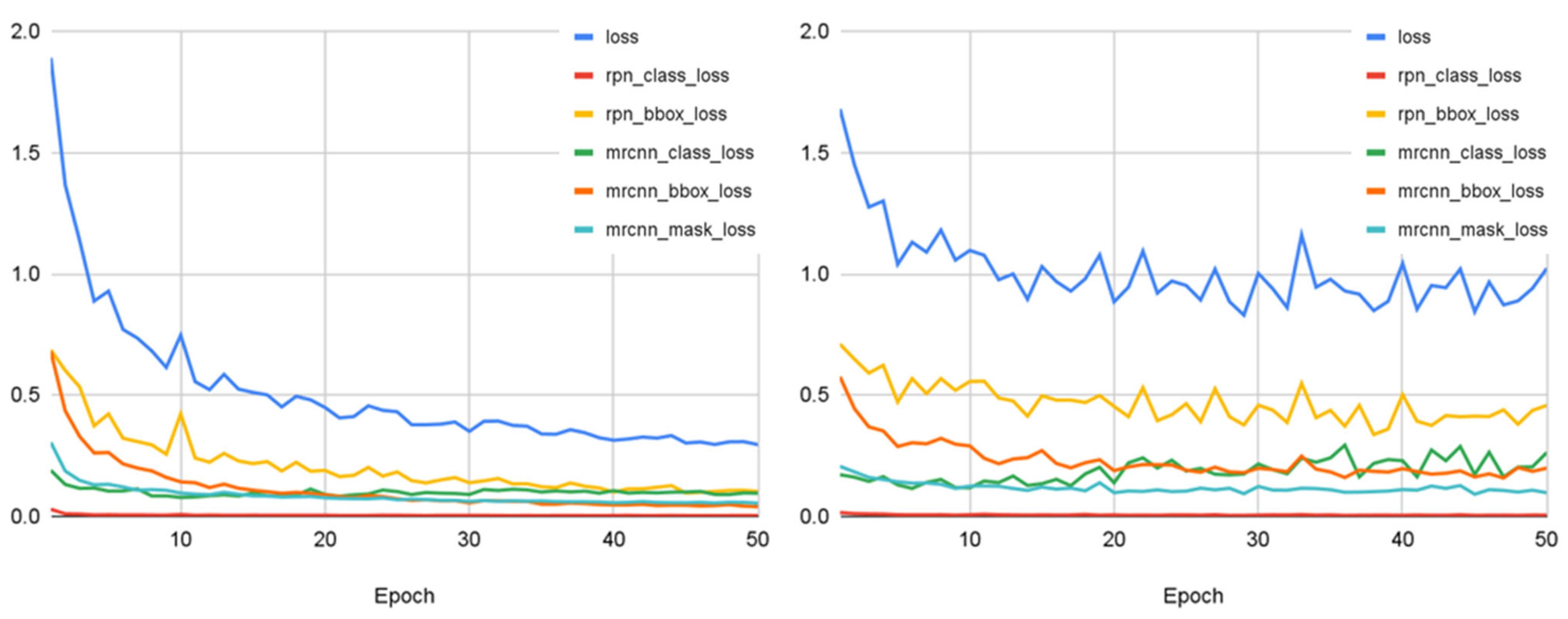
5.2.2. Module 2
5.2.3. Module 3
5.3. Discussion and Limitations
6. Conclusions
Author Contributions
Funding
Data Availability Statement
Acknowledgments
Conflicts of Interest
References
- Mittal, S.; Khan, M.A.; Romero, D.; Wuest, T. Smart manufacturing: Characteristics, technologies and enabling factors. Proc. Inst. Mech. Eng. Part B J. Eng. Manuf. 2019, 233, 1342–1361. [Google Scholar] [CrossRef]
- Martinez, P.; Al-Hussein, M.; Ahmad, R. Online vision-based inspection system for thermoplastic hot plate welding in window frame manufacturing. Procedia CIRP 2020, 93, 1316–1321. [Google Scholar] [CrossRef]
- Narula, S.; Prakash, S.; Dwivedy, M.; Talwar, V.; Tiwari, S.P. Industry 4.0 adoption key factors: An empirical study on manufacturing industry. J. Adv. Manag. Res. 2020, 17, 697–725. [Google Scholar] [CrossRef]
- Roslan, Q.; Ibrahim, S.H.; Affandi, R.; Nawi, M.N.M.; Baharun, A. A literature review on the improvement strategies of passive design for the roofing system of the modern house in a hot and humid climate region. Front. Archit. Res. 2016, 5, 126–133. [Google Scholar] [CrossRef]
- Aldawoud, A. Windows design for maximum cross-ventilation in buildings. Adv. Build. Energy Res. 2017, 11, 67–86. [Google Scholar] [CrossRef]
- Takada, K.; Hayama, H.; Mori, T.; Kikuta, K. Thermal insulated PVC windows for residential buildings: Feasibility of insulation performance improvement by various elemental technologies. J. Asian Archit. Build. Eng. 2021, 20, 340–355. [Google Scholar] [CrossRef]
- Martinez, P.; Ahmad, R. Quantifying the Impact of Inspection Processes on Production Lines through Stochastic Discrete-Event Simulation Modeling. Modelling 2021, 2, 406–424. [Google Scholar] [CrossRef]
- Kermani, A.P.; Abbaslu, L.; Alizadeh Shahi, S.R. A Model to Plan the Operations and Control the Orders (The Case Study: Profile Door and Window Manufacturing (UPVC)). Biomed. Pharmacol. J. 2015, 8, 219–229. [Google Scholar] [CrossRef]
- Machado, A.A.; Zayatz, J.C.; da Silva, M.M.; Neto, G.M.; Leal, G.C.L.; Lima, R.H.P. Aluminum bar cutting optimization for door and window manufacturing. DYNA 2020, 87, 155–162. [Google Scholar] [CrossRef]
- Itani, A.; Alghamdy, M.; Nazir, H.; Sharma, S.; Ahmad, R. A decision-making tool to integrate lean 4.0 in windows manufacturing using simulation and optimization models. In Proceedings of the 32nd European Modeling & Simulation Symposium (EMSS 2020), online, 16–18 September 2020; pp. 137–145. [Google Scholar] [CrossRef]
- Pérez, L.; Rodríguez, Í.; Rodríguez, N.; Usamentiaga, R.; García, D. Robot Guidance Using Machine Vision Techniques in Industrial Environments: A Comparative Review. Sensors 2016, 16, 335. [Google Scholar] [CrossRef]
- Shah, H.N.M.; Sulaiman, M.; Shukor, A.Z.; Rashid, M.Z.A. Recognition of Butt Welding Joints using Background Subtraction Seam Path Approach for Welding Robot. Int. J. Mech. Mechatron. Eng. 2017, 17, 57–62. [Google Scholar]
- Abdelaal, M.; Farag, R.M.A.; Saad, M.S.; Bahgat, A.; Emara, H.M.; El-Dessouki, A. Uncalibrated stereo vision with deep learning for 6-DOF pose estimation for a robot arm system. Robot. Auton. Syst. 2021, 145, 103847. [Google Scholar] [CrossRef]
- Kleppe, A.; Bjørkedal, A.; Larsen, K.; Egeland, O. Automated Assembly Using 3D and 2D Cameras. Robotics 2017, 6, 14. [Google Scholar] [CrossRef]
- Levine, S.; Pastor, P.; Krizhevsky, A.; Ibarz, J.; Quillen, D. Learning hand-eye coordination for robotic grasping with deep learning and large-scale data collection. Int. J. Robot. Res. 2018, 37, 421–436. [Google Scholar] [CrossRef]
- Lei, T.; Rong, Y.; Wang, H.; Huang, Y.; Li, M. A review of vision-aided robotic welding. Comput. Ind. 2020, 123, 103326. [Google Scholar] [CrossRef]
- Chen, S.B.; Zhang, Y.; Qiu, T.; Lin, T. Robotic Welding Systems with Vision-Sensing and Self-learning Neuron Control of Arc Welding Dynamic Process. J. Intell. Robot. Syst. 2003, 36, 191–208. [Google Scholar] [CrossRef]
- Micallef, K.; Fang, G.; Dinham, M. Automatic Seam Detection and Path Planning in Robotic Welding. In Robotic Welding, Intelligence and Automation; Springer: Berlin/Heidelberg, Germany, 2011; pp. 23–32. [Google Scholar] [CrossRef]
- Dinham, M.; Fang, G. Autonomous weld seam identification and localisation using eye-in-hand stereo vision for robotic arc welding. Robot. Comput. Integr. Manuf. 2013, 29, 288–301. [Google Scholar] [CrossRef]
- Duan, Y. Welding Seam Recognition Robots Based on Edge Computing. In Proceedings of the 2020 International Conference on Computing and Data Science (CDS), Stanford, CA, USA, 1–2 August 2020; pp. 27–30. [Google Scholar] [CrossRef]
- Tian, Y.; Liu, H.; Li, L.; Yuan, G.; Feng, J.; Chen, Y.; Wang, W. Automatic Identification of Multi-Type Weld Seam Based on Vision Sensor with Silhouette-Mapping. IEEE Sens. J. 2021, 21, 5402–5412. [Google Scholar] [CrossRef]
- Rout, A.; Deepak, B.B.V.L.; Biswal, B.B. Advances in weld seam tracking techniques for robotic welding: A review. Robot. Comput. Integr. Manuf. 2019, 56, 12–37. [Google Scholar] [CrossRef]
- Xu, J.; Zhang, G.; Hou, Z.; Wang, J.; Liang, J.; Bao, X.; Yang, W.; Wang, W. Advances in Multi-robotic Welding Techniques: A Review. Int. J. Mech. Eng. Robot. Res. 2020, 9, 421–428. [Google Scholar] [CrossRef]
- Minaee, S.; Boykov, Y.Y.; Porikli, F.; Plaza, A.J.; Kehtarnavaz, N.; Terzopoulos, D. Image Segmentation Using Deep Learning: A Survey. IEEE Trans. Pattern Anal. Mach. Intell. 2021, 44, 3523–3542. [Google Scholar] [CrossRef] [PubMed]
- Huang, H.; Wei, Z.; Yao, L. A Novel Approach to Component Assembly Inspection Based on Mask R-CNN and Support Vector Machines. Information 2019, 10, 282. [Google Scholar] [CrossRef]
- Qianqian, Z.; Sen, L.; Weiming, G. Research on Vehicle Appearance Component Recognition Based on Mask R-CNN. J. Phys. Conf. Ser. 2019, 1335, 012026. [Google Scholar] [CrossRef]
- Xia, C.; Pan, Z.; Zhang, S.; Polden, J.; Li, H.; Xu, Y.; Chen, S. Mask R-CNN-Based Welding Image Object Detection and Dynamic Modelling for WAAM. In Transactions on Intelligent Welding Manufacturing; Springer: Berlin/Heidelberg, Germany, 2020; pp. 57–73. [Google Scholar] [CrossRef]
- He, F.; Sun, X.; Wang, Y.; Rong, S.; Hu, Y. Research on Weld Recognition Method Based on Mask R-CNN. In Proceedings of the 2021 IEEE Asia-Pacific Conference on Image Processing, Electronics and Computers (IPEC), Dalian, China, 14–16 April 2021; pp. 545–551. [Google Scholar] [CrossRef]
- Jin, X.; Lv, L.; Chen, C.; Yang, F.; Chen, T. A New Welding Seam Recognition Methodology Based on Deep Learning Model MRCNN. In Proceedings of the 2020 7th International Conference on Information, Cybernetics, and Computational Social Systems (ICCSS), Guangzhou, China, 13–15 November 2020; pp. 767–771. [Google Scholar] [CrossRef]
- Yang, Y.; Li, Z.; Yu, X.; Li, Z.; Gao, H. A trajectory planning method for robot scanning system using mask R-CNN for scanning objects with unknown model. Neurocomputing 2020, 404, 329–339. [Google Scholar] [CrossRef]
- Hevner, A.R.; March, S.T.; Park, J.; Ram, S. Design Science in Information Systems Research. MIS Q. 2004, 28, 75. [Google Scholar] [CrossRef]
- Illingworth, J.; Kittler, J. A survey of the hough transform. Comput. Vis. Graph. Image Process. 1998, 44, 87–116. [Google Scholar] [CrossRef]
- Zhang, Z. A flexible new technique for camera calibration. IEEE Trans. Pattern Anal. Mach. Intell. 2000, 22, 1330–1334. [Google Scholar] [CrossRef]
- Dutta, A.; Zisserman, A. The VIA Annotation Software for Images, Audio and Video. In Proceedings of the 27th ACM International Conference on Multimedia, Nice, France, 21–25 October 2019; pp. 2276–2279. [Google Scholar] [CrossRef]
- Wang, S.; Sun, G.; Zheng, B.; Du, Y. A Crop Image Segmentation and Extraction Algorithm Based on Mask RCNN. Entropy 2021, 23, 1160. [Google Scholar] [CrossRef]


| # | Coordinates of the Starting Point (x, y) | |||||||||
|---|---|---|---|---|---|---|---|---|---|---|
| Virtual Environment | Real Environment | |||||||||
| Estimated | Actual | Error | Estimated | Actual | Error | |||||
| x [mm] | y [mm] | x [mm] | y [mm] | ε [mm] | x [mm] | y [mm] | x [mm] | y [mm] | ε [mm] | |
| 1 | 494 | −497 | 496 | −499 | 2.828 | 486 | −510 | 489 | −506 | 5.000 |
| 2 | 499 | −490 | 501 | −503 | 13.153 | 470 | −488 | 467 | −479 | 9.487 |
| 3 | 488 | −504 | 492 | −510 | 7.211 | 478 | −502 | 481 | −496 | 6.708 |
| 4 | 512 | −508 | 510 | −516 | 8.246 | 478.0 | −497 | 475 | −499 | 3.606 |
| 5 | 502 | −509 | 507 | −501 | 9.434 | 472 | −500 | 471 | −502 | 2.236 |
| 6 | 469 | −405 | 476 | −401 | 8.062 | 496 | −408 | 500 | −401 | 8.062 |
| 7 | 490 | −388 | 497 | −391 | 7.616 | 512 | −388 | 500 | −390 | 12.166 |
| 8 | 482 | −393 | 480 | −405 | 12.166 | 488 | −420 | 494 | −415 | 7.810 |
| 9 | 485 | −402 | 480 | −398 | 6.403 | 496 | −420 | 500 | −412 | 8.944 |
| 10 | 483 | −401 | 481 | −405 | 4.472 | 497 | −413 | 498 | −400 | 13.038 |
| 11 | 589 | −499 | 593 | −501 | 4.472 | 602 | −498 | 600 | −500 | 2.828 |
| 12 | 586 | −502 | 592 | −508 | 8.486 | 596 | −480 | 597 | −483 | 3.162 |
| 13 | 605 | −509 | 608 | −505 | 5.000 | 604 | −518 | 601 | −515 | 4.242 |
| 14 | 601 | −505 | 602 | −503 | 2.236 | 598 | −483 | 600 | −481 | 2.828 |
| 15 | 600 | −487 | 601 | −480 | 7.071 | 601 | −495 | 610 | −496 | 9.055 |
| Average [mm] | 7.124 | Average [mm] | 6.612 | |||||||
| Standard Deviation [mm] | 2.975 | Standard Deviation [mm] | 3.390 | |||||||
| IoU | 0.5 | 0.6 | 0.7 | 0.75 | 0.8 | 0.85 | 0.9 | 0.95 |
| mAP | 0.953 | 0.851 | 0.784 | 0.755 | 0.707 | 0.664 | 0.611 | 0.512 |
Disclaimer/Publisher’s Note: The statements, opinions and data contained in all publications are solely those of the individual author(s) and contributor(s) and not of MDPI and/or the editor(s). MDPI and/or the editor(s) disclaim responsibility for any injury to people or property resulting from any ideas, methods, instructions or products referred to in the content. |
© 2023 by the authors. Licensee MDPI, Basel, Switzerland. This article is an open access article distributed under the terms and conditions of the Creative Commons Attribution (CC BY) license (https://creativecommons.org/licenses/by/4.0/).
Share and Cite
Tung, T.-J.; Al-Hussein, M.; Martinez, P. Vision-Based Guiding System for Autonomous Robotic Corner Cleaning of Window Frames. Buildings 2023, 13, 2990. https://doi.org/10.3390/buildings13122990
Tung T-J, Al-Hussein M, Martinez P. Vision-Based Guiding System for Autonomous Robotic Corner Cleaning of Window Frames. Buildings. 2023; 13(12):2990. https://doi.org/10.3390/buildings13122990
Chicago/Turabian StyleTung, Tzu-Jan, Mohamed Al-Hussein, and Pablo Martinez. 2023. "Vision-Based Guiding System for Autonomous Robotic Corner Cleaning of Window Frames" Buildings 13, no. 12: 2990. https://doi.org/10.3390/buildings13122990
APA StyleTung, T.-J., Al-Hussein, M., & Martinez, P. (2023). Vision-Based Guiding System for Autonomous Robotic Corner Cleaning of Window Frames. Buildings, 13(12), 2990. https://doi.org/10.3390/buildings13122990