Abstract
The cementitious jet grout method (CJG) is one of the most preferred methods for the ground reinforcement of building foundations. As a result of the soil improvement made with the CJG, it was observed that there was a decrease in settlement, permeability, and liquefaction potential and an increase in the bearing capacity. In this study, columns with different grouting pressures (400, 450, and 500 bar) and water/cement ratios of 0.75, 1.00, and 1.25 were produced on several soil types (sand, clay, and alluvial soil) that have high liquefaction, settlement potential, and low bearing capacity. CJG columns were kept for 28 days after completion and then removed from the soil, and diameter measurements were made and significant differences were observed according to pressure and w/c ratios. Three samples were taken in CJG columns extracted from the ground. Laboratory tests were conducted to determine the physical (water absorption rate, density, and porosity) and mechanical (UCS and UPV) properties of CJG column samples. The highlighting of this paper is to build full-scale CJG columns in sandy soil, clay soil, and alluvial soil, increase the geotechnical engineering properties, and investigate the strength development, and diameter under different w/c ratios and different injection pressures. The strength of CJG columns in sandy soils was found between 36 and 15 MPa, in clay soils between 15 and 4 MPa and in alluvial soils between 32 and 15 MPa. Moreover, it was observed that there was a significant increase in the diameters with the increase in the injection pressure and a decrease in the compressive strengths. When the CJG column diameters were compared with constant injection pressure and increasing w/c ratios, the maximum increase was found to be 13% for sandy soils, 10% for clayey soils, and 14% for alluvial soils. The column diameters were 37% larger for sandy soils than clayey soils and 26% larger than alluvial soils at the same w/c ratio and constant injection pressure. In conclusion, since the results found in this study were made on a real scale in the field and for three different soil conditions, the results can be used directly in future engineering applications.
1. Introduction
If the soil properties are insufficient according to the soil bearing capacity, liquefaction, permeability, settlement, or stability criteria, deep foundation system application or soil improvement is required. There are several soil improvement methods. Soil properties are important when selecting one of them. In addition, it is necessary to specify which soft soil properties should be improved [1,2]. By selecting a suitable method according to the soil parameters, improving the soil and as a result, the bearing capacity increases, settlements and impermeability decrease, and liquefaction resistance increases [3,4,5,6,7,8,9].
With the development of technology, the jet grout method, which is a soil improvement method, has become an effective method for solving many geotechnical engineering problems. The CJG method was first introduced in England in the 1950s and used in Japan for geotechnical engineering purposes [10,11]. The jet grout method is a specialized ground improvement and foundation construction technique used in geotechnical engineering and construction. It is employed to create soil columns or barriers in the ground by injecting high-pressure grout (a mixture of cement, water, and sometimes other additives) into the soil. The CJG method comprises two stages: drilling and injection. This method aims to increase the mechanical strength of the soil. Therefore, the bearing capacity and modulus of elasticity of the soil increased and its permeability decreased. With the jet grouting method, it is possible to improve very wide and different types of soils with different properties, such as clay or sand–gravel soils [12,13,14,15,16].
This CJG method is accomplished using a high-energy grout jet that breaks up the ground. In this way, it is ensured that the soil/cement mixture (soilcrete) column, which is defined as the jet grout column, is in a better condition in terms of tension, durability, compression, and permeability compared to the condition of the ground before the improvement. The dimensions of the columns you want to create depend on the characteristics of the soil types, as well as depending on, nozzle diameter and quantity (jetting types), cementitious grout flow, cementitious grout pressure, lifting speed, and rotating speed [17,18,19,20].
There are generally three primary types of jet grouting techniques or methods, each with a specific application and purpose. Single-fluid jet grouting: In this method, a single fluid (typically a mixture of cement, water, and sometimes additives) is injected into the ground at high pressure through a single nozzle. Single fluid jet grouting is commonly used for creating soil/cement columns or barriers to improve soil properties, stabilize foundations, or control groundwater. Double-fluid jet grouting involves the simultaneous injection of two fluids: a high-velocity stream of grout (typically cement and water) and a low-velocity stream of air or water. Two fluids are combined at the nozzle, and this method is often used when greater control over the grout mixture and column dimensions is required. It is suitable for creating more precise columns and barriers in challenging soil conditions. Triple-fluid jet grouting adds a third fluid to the mix, which is usually a lubricating fluid, such as air or water. This method is used to achieve even greater precision and control over the jet grouting process, allowing for the creation of very fine, high-strength columns or barriers. It is particularly useful in sensitive or complex projects, where precise engineering is required [17,18,19,20,21,22].
Grout pressure is one of the most effective parameters for forming the desired column diameter, and there is a relationship between injection pressure and column diameter. As the pressure increased, the column diameter also increased. However, to obtain a homogeneous column of the desired diameter, the pressure value is required, but this alone is not sufficient. Because other parameters, such as tensile and rotational speeds, are also related to time, the formation of columns of the same diameter and homogeneity is also associated with the time factor [19,20,21,22,23].
When looking at the literature, it can be seen that CJG has been extensively studied a lot in the laboratory. In the studies, it has been tried to improve the strength properties with different materials. The effects of curing time, cement type, soil density, and chemical reactions on soil strength were determined primarily using strength tests such as unconfined pressure tests in laboratory conditions [17,18,19,20,21,22,23,24].
Çınar et al. [17] conducted an experimental study in the laboratory to investigate the effect of waste marble powder on the fluidity and rheological properties of cement-based grout mixtures. In addition, clay was added to the mixtures, and the determination of the effect on the strength properties was attempted in the laboratory. Similarly, Çelik and Akçuru [18] investigated the fluidity and rheological properties of grout mixtures by adding bottom ash in laboratory experiments. Seiphoori and Zamanian [19] and Nagaraju et al. [20] study created permeation grout mixtures by creating mixtures to affect the properties of clays for soil stabilization. The results suggest the application of clay nanoparticle solutions for a more economical and environmentally friendly grouting approach compared to cement, which likely results in the formation of chemically more stable interparticle bonds. Çanakcı et al. [24] conducted experiments using glass fiber in the laboratory for the deep mixing method, which is a different improvement method. They concluded that the optimum glass fiber percentage is 3% to investigate better strength performance after 28 days of curing of the specimens for all clay contents. During the 7th and 14th day of curing periods, it was observed that the strength performance generally increased with the increase in glass powder, and the strength also increased with the increase in the sand ratio in the clay content.
The literature has also shown that full-scale samples’ strength properties are much lower than laboratory samples. Also, the actual construction situation and common unknowns are not presented in the laboratory. Therefore, it is necessary to create real CJG columns in the field and look at their properties. The most important goal of this study is to produce real scale CJG columns in different soil types and different water/cement ratios.
Looking at the literature, there are limited real-scale studies. Hasan and Çanakcı [25] constructed seven full-scale jet grouting columns in clayey soil with different pressure injections (300 to 400 bar), jet grouting rotations (25, 35, 45 rpm), and w/c ratio of 1. These parameters were used to study the geomechanical properties of jet grout, such as strength properties (UCS) and jet grout–soil surface friction. The average strength variation for pressure and rotation was 38% and 9%, respectively. The maximum surface friction angles were 19° and 18°. During the investigation of the diameter and length parameters of the jet grout, it was concluded that in previous studies the length and diameter of the jet grout were indicated as the main important factors in the geometry of the grout column about the prediction approaches [23,24]. It is not difficult to check the length of the grout column because it can be justified using drill rods. Therefore, controlling and measuring the jet grout diameter has been considered as the main part in jet grouting methods, so Hasan and Çanakcı [25] presented the measurement and estimation of the diameter of the grout column and the clarification of the parameters that influence the size of the diameter. However, it has been observed that there are no studies in the literature at high pressures (400, 450, and 500), different water/cement ratios (0.75, 1.00, and 1.25), and three different soil types (sand, clay, and alluvial soil).
Within the scope of this study, specially designed CJG columns were manufactured at three different construction sites in Kahramanmaraş province, which is located in the first earthquake zone of Turkey. This site work understanding of geomechanical properties of full-scale CJG columns during injecting in sandy soil, clayey soil, and alluvial soil. Furthermore, this study investigated the effect of CJG on the strength values of the columns of CJG at different w/c ratios, different grouting pressures, and different soil types, and the diameter variations of CJG columns and revealed the lack of knowledge in this field. Therefore, the innovation of this paper is to build CJG columns in sandy soil, clay soil, and alluvial soil, increase the geotechnical engineering properties, and investigate the strength development and diameter under different w/c ratios and different injection pressure. Different water/cement ratios are considered as important parameters to show the significant effect of the CJG column during grouting in three different ground conditions. In conclusion, since the results found in this study were obtained on a real scale in the field and for three different soil conditions, the results can be used directly in future engineering applications.
2. Materials and Methods
2.1. Material
The locations used in this study were specifically 3 locations with different soil types. The locations of these places in Kahramanmaraş are 37°35′29.7″ N 36°50′11.6″ E Onikişubat providence, 37°34′56.2″ N 37°8′49.9″ E Dulkadiroğlu providence, and 37°22′34.0″ N 36°50′24.9″ E Türkoğlu district. Figure 1 shows their locations on the map. Furthermore, soil properties were obtained according to the requirements of the ASTM standard. According to the Unified Soil Classification System (USCS) [26,27], the soil in location 1 was determined as sandy soil (SW), in location 2 as clayey soil (CL), and location 3 as alluvial soil (SC). Soil samples were tested to determine their physical and chemical properties at Kahramanmaraş Sütçü İmam University Civil Engineering Department Soil Mechanics Laboratory. All soil properties according to soil tests are detailed in Table 1.
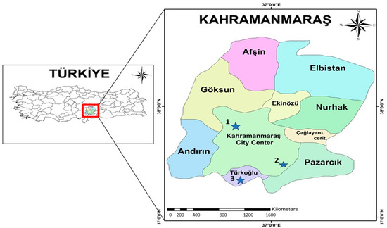
Figure 1.
Points in Kahramanmaraş city where samples were taken and CJG columns were produced.

Table 1.
Soil properties.
The full-scale CJG column was constructed on site with water/cement ratios of 0.75, 1.00, and 1.25 to analyze the geomechanics and variation of CJG diameter in different soils. In the literature, it is known that a w/c ratio of 0.75 and above is used especially for clay and sandy soils [15,17,20]. Additionally, the Portland cement used in this study is Portland cement (PC) type CEM I-42.5R according to ASTM C150 [28], and the chemical and physical properties of PC are given detailed in Table 2.
Table 2.
Chemical and physical properties of PC.
2.2. Method
2.2.1. CJG Column Preparation and Sample Collection
CJG columns with 400, 450, and 500 bar grouting pressures and water/cement ratios of 0.75, 1.00, and 1.25 were produced on sandy soil, clayey soil, and alluvial soil. For each w/c ratio and grout pressure, 3 m columns were produced. During the preparation of CJG columns, the pullout speed and rotation speed were kept constant (Table 3). In addition, in the case study, the jet grouting method was chosen as the double-fluid method. This method was described in detail in the introduction.
Table 3.
Material and soil types information from CJG column.
After CJG columns were prepared in 3 different soil types, they were kept for 28 days to take samples. At the end of 28 days, the CGJ columns were excavated and removed from the site (Figure 2). Each CJG column is 3 m long. Three samples were taken from each CJG column: one in the middle, one on the left, and one on the right, from depths of 1.5 m.
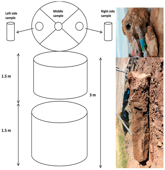
Figure 2.
CJG column was prepared in the field and removed after 28 days and a Schematic representation of the sampling points.
The test samples were named in 3 different soil types, sandy, clayey, and alluvial soil, at different pressures such as 400, 450, and 500 bar, and w/c ratios of 0.75, 1.00, and 1.25; the labelling is such that, for example, S-CJG400-0.75 indicates CJG cementitious jet grout specimen, S soil type, 400 bar pressure injection, and 0.75 w/c ratio of jet grout, as detailed in Table 3. In addition, three samples were taken at the same depth of each column: right side, left side, and middle side. Nomenclature is the following: S-CJG400-0.75 RS, S-CJG400-0.75 LS, S-CJG400-0.75 MS.
2.2.2. Test Techniques
After 28 days of CJG manufacturing, samples were taken from all columns and brought to the Kahramanmaraş Sütçü İmam University laboratory (Figure 3). All samples were applied to mechanical tests to examine the mechanical and physical properties of the CJG column. Mechanical tests are unconfined compressive tests (UCS) and ultrasonic pulse velocity (UPV), and physical tests are water absorption, density, and porosity.
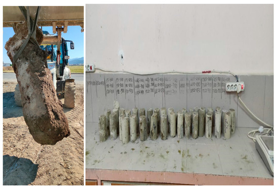
Figure 3.
CJG column brought from the field and samples taken from the CJG column.
UCS is a type of laboratory test used in geotechnical engineering and soil mechanics to determine the unconfined compressive strength of a soil or rock material. This test is primarily used to assess the load-bearing capacity of soils and rocks under axial compression. The strength properties of CJG columns formed in 3 different soil types, different w/c ratios, and different pressures were found according to ASTM D2166 standards [29].
An ultrasonic pulse velocity test, often referred to simply as an ultrasonic test (UT), is a non-destructive testing (NDT) technique used to determine the velocity of sound waves through a material. This test is typically used for assessing the integrity and properties of materials, including metals, plastics, ceramics, concrete, and grout. The ultrasonic velocity test is often combined with other techniques and measurements, including the measurement of velocity, to gather valuable information about the material being tested. The UPV test can detect the presence of voids or delimitation within the jet grout columns. Voids or incomplete grout distribution can weaken the columns and compromise their load-bearing capacity. The test helps locate such issues so that corrective measures can be taken. The UPV test provides information about the uniformity of the grout distribution within the columns. Variations in grout density or inconsistencies in grout mixing can lead to non-uniform columns, which may not perform as intended. Detecting these variations helps ensure that the columns are constructed according to design specifications. In this work, UPV testing was performed for CJG column samples after 28 days of curing in the field according to ASTM C597-16 [30] requirements. A pulse generator sends a short burst of high-frequency ultrasound waves (typically in the megahertz range) into the material. One transducer emits the pulse, and the other receives it.
Water absorption, density, and porosity tests for jet grout are important for several reasons, as they provide valuable information about the properties, quality, and durability of the jet grout material and columns. The results of these tests can guide engineers in optimizing the mix design of the grout. For instance, knowing the water absorption capacity can help determine the right water/cement ratio to achieve the desired strength and durability. Density and porosity measurements can also inform mix design adjustments. The density and porosity of jet grout columns are directly related to their structural integrity. Higher density and lower porosity typically result in stronger, more stable columns capable of bearing the required loads. An increase in porosity or a decrease in density may indicate the presence of voids or areas of incomplete grout distribution within the columns. These voids can compromise the columns’ load-bearing capacity and stability. Detecting them early is crucial for addressing potential issues [25]. Water absorption, density, and porosity tests were performed according to ASTM C20-00 standards [31] to determine the physical properties of the samples brought from the field.
3. Results and Discussion
In this study, the mechanical properties and physical properties of CJG columns formed in different soil types, different w/c ratios, and different injection pressures, and the changes in column diameters in different cases are discussed, respectively.
3.1. The Mechanical Properties of CJG Columns
The mechanical properties of CJG columns are critically important because they directly impact the performance and effectiveness of jet grouting as a ground improvement or foundation support technique. Understanding and controlling these properties are essential for ensuring the stability, load-bearing capacity, and durability of structures that rely on jet grout columns. In the literature, it can be seen that studies have been carried out for some soil types to determine the strength of jet grouts [25,32]. Parameters that directly affect the strength of CJG columns are injection speed, water/cement ratio, pullout speed, and soil types.
In this study, the 28-day compressive strength of CJG columns in different soil types, different injection pressures, and different w/c ratios was examined and are shown in Figure 4a–c. Considering other studies in the literature, only the 28-day strength was examined in this study, since the curing time does not have much effect on strength after 28 days. It is shown in Figure 5a. When looking at the UCS test results, it was generally found that the columns formed in sandy soils were in the range of 15 to 36 MPa; for the columns formed in clayey soils, it was 4 to 15 MPa; and for the alluvial soil, it was 15–32 MPa. In previous studies, it was found that the range of 10–30 MPa was found for coarse-grained soils and 1.5–15 MPa for fine-grained soils [23,24,25,32].
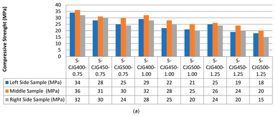
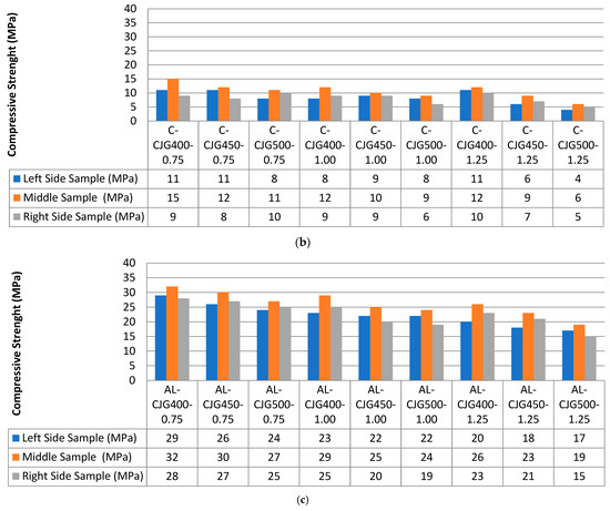
Figure 4.
CJG column compressive strength values according to different soil types, different w/c ratios, and different injection pressures: (a) sandy soil; (b) clayey soil; (c) alluvial soil.
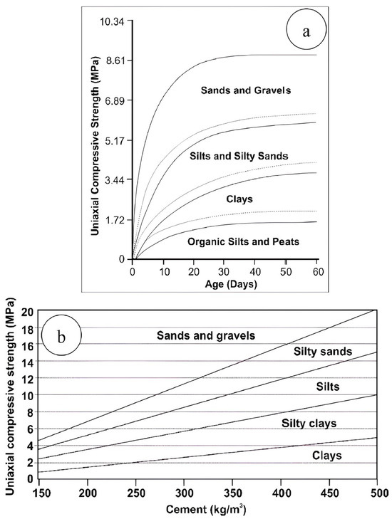
Figure 5.
Variation in UCS with (a) time and (b) cement rate for different soil types [32].
Regardless of soil type, soilcrete strengths appear to decrease as injection pressure increases. In addition, since the grout mixture can penetrate better in coarse-grained soils, its compressive strength is higher than in fine-grained soils. Considering the results of CJG columns samples with a w/c ratio of 1 and an injection pressure of 400 bar, the strength for the center sample was found to be 32 MPa in sandy soil, 29 MPa in Alluvial soil, and 12 MPa in clayey soil.
The water/cement ratio is of great importance in the compressive strength of CJG columns. In Figure 4, it is seen that as the w/c ratio increases, soilcrete strength decreases in all soil types. Increasing the w/c ratio may benefit fluidity and pumpability, but it has been shown to seriously affect the strength of soilcrete. Similar results were found in studies in the literature and are shown in Figure 5b.
In addition, samples were taken in the middle, right, and left due to the rotation effect of CJG columns and their results were found. According to soil types, the highest value was always found in the middle sample. Because the cementitious grout mixed with the soil in the ground negatively affected its strength for left and right side samples. For sandy soils, the samples taken from the right and left were determined to be closer to the middle sample value.
The ultrasonic pulse velocity (UPV) test is important for jet grout columns for several reasons, as it provides valuable information about the quality, integrity, and properties of these columns. The UPV test can offer insights into the long-term durability of jet grout columns. It can help assess the potential for degradation due to factors like freeze–thaw cycles or chemical exposure, which can impact the velocity of sound waves through the material. Unlike destructive testing methods that require core samples, the UPV test is non-destructive, meaning it does not damage the jet grout columns. This is especially important when the columns are intended to provide foundation support or ground improvement for structures [25,32,33].
According to the UPV test results in this study, the maximum value on sandy soils was found to be 3650 m/s and the minimum value was 2950 m/s. Also, it was found between 2480 m/s and 1650 m/s for clayey soils and between 3420 m/s and 2750 m/s for alluvial soils. Figure 6 shows the results for three soil types and different injection pressures and different w/c ratios. According to the UPV test results stated in the literature; those above 5000 m/s are defined as very high speed, those between 4000 and 5000 m/s as high speed, those between 3500 and 4000 m/s as medium speed, those between 2500 and 3500 m/s as low speed, and those less than 2500 m/s as very low speed [25,32,33]. According to the specified values, S-CJG400-0.75, S-CJG450-0.75, and S-CJG400-1.00 samples were found to have medium speed in sandy soil, while other sandy soil samples were found to have low speed. The result of UPV tests performed on CJG columns produced in clay soil was determined as very low velocity since it was less than 2500 m/s. According to the test results of CJG columns produced in alluvial soils, the UPV test result was found to be low velocity since it was between 2500 and 3500 m/s. The elastic modulus values of the CJG columns found according to the UPV test results are 0.086–0.102 MPa for sandy soils, 0.051–0.068 MPa for clayey soils, and 0.078–0.097 MPa for alluvial soils.
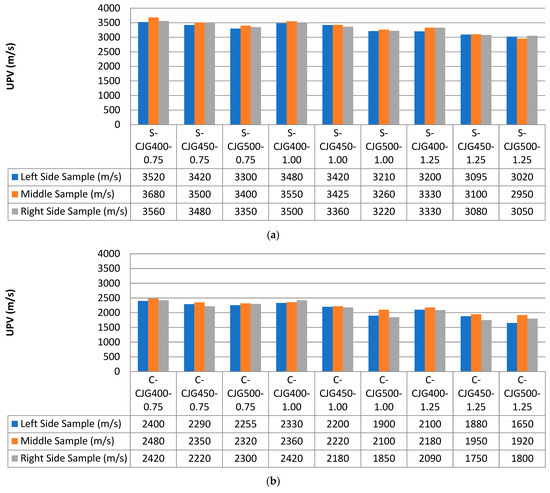
Figure 6.
UPV test results of CJG column: (a) sandy soil; (b) clayey soil; (c) alluvial soil.
When analyzed according to soil types, the UPV test results were the highest for sandy soils, followed by alluvial soils and finally clayey soils, where the sandy soil formed a more compact and homogeneous CJG column. Also, increasing the w/c ratio and injection pressure decreased the UPV test results. Because the increase in the w/c ratio increased the fluidization, it allowed more soil particles to enter the CJG columns. Similarly, UPV test results decreased with increasing injection pressure as the CJG column of soil particles increased. In addition, the modulus of elasticity of the CBJ column formed in sandy soils was higher. This is because the elasticity value increases as the strength property increases [25,32].
In summary, the mechanical properties (UCS and UPV tests) of jet grout columns are pivotal in determining the effectiveness and reliability of this ground improvement technique. These properties influence the structural performance, stability, and safety of foundations and other structures. Therefore, precise control and measurement of these properties are crucial in geotechnical engineering and construction projects where jet grouting is employed.
3.2. The Physical Properties of CJG Columns
Density, water absorption, and porosity tests provide insights into the durability of jet grout columns. High water absorption or porosity can indicate that the grout material is susceptible to moisture infiltration, which may lead to deterioration over time. Lower-density grout may also be more prone to freeze–thaw damage in cold climates. The density and porosity of jet grout columns are directly related to their structural integrity. Higher density and lower porosity typically result in stronger, more stable columns capable of bearing the required loads. All experiments performed in this section are according to the standard [34,35,36].
In this study, it was observed that CJG columns in sandy soil had the highest density. The highest density value was found to be 1.75 g/cm3 and the lowest value was 1.58 g/cm3. The highest and lowest densities of alluvial and clay soils were found to be 1.62–1.40 g/cm3 and 1.32–1.03 g/cm3, respectively. Figure 7 shows the results for the three soil types. The highest value was found because the CJG columns formed in sandy soils have a more homogeneous structure.

Figure 7.
CJG column density changes according to (a) sandy soil; (b) clayey soil; (c) alluvial soil.
In addition, the densities of the three soil types decreased significantly as the w/c ratio increased and the grouting pressure increased. Similarly, when samples from the middle, right, and left of the CJG columns were analyzed, the samples in the middle were generally found to have the highest density. This is because there are fewer soil particles in the center than in the right and left sides. Although there are no results for different w/c ratios in the literature, close values were found for different injection pressures and different soil types [25,35].
Water absorption tests were performed according to ASTM D6473-15 [37] standard. As the amount of soil particles inside the CJG columns increases, the water absorption potential increases. As seen in Figure 8, it is observed that the water absorption rate increases with the increase in w/c ratio and injection pressure for all soil types.
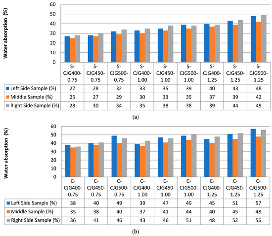
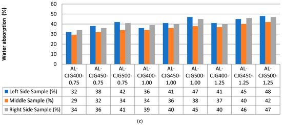
Figure 8.
CJG column water absorption changes according to (a) sandy soil; (b) clayey soil; (c) alluvial soil.
The maximum and minimum water absorption of CJG columns formed in sandy soils were found to be 49% and 25%. The maximum–minimum values for alluvial and clayey soils were found to be 48–29% and 57–38%, respectively. In general, the water absorption of the samples taken from the center of the CJG columns is lower than the water absorption of the samples taken from the right and left sides. This is because the soil grains mix more on the outer surface during the formation of the CJG column [25].
Porosity is a measure of the amount of open space or voids that exist within the jet grout columns. High porosity can indicate that the grout columns can be susceptible to moisture infiltration, which can lead to degradation over time. The porosity test helps assess the potential for long-term durability and resistance to environmental factors, including freeze–thaw cycles and chemical exposure.
The results of all porosity experiments performed are shown in Figure 9. Especially if there are fine-grained soils in the region where CJG columns are manufactured, the porosity is observed much more than coarse-grained soils. According to the test results, the porosity was found to be 28–50% in sandy soils, 47–61% in clay soils and 32–49% in alluvial soils. In all three soil types, it was observed that as the w/c ratio increased and the injection pressure increased, the porosity increased. Past studies have found a similar range of results for different soil types [25,38].
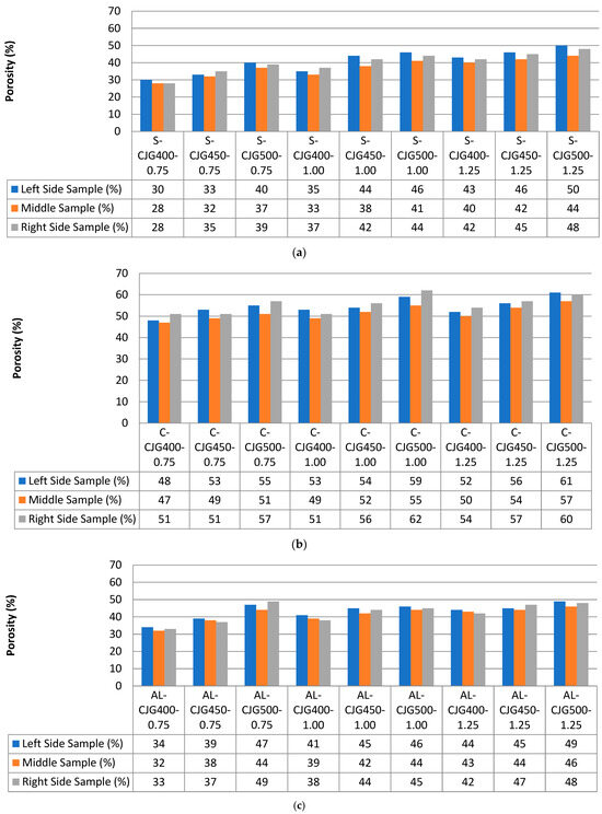
Figure 9.
CJG column porosity changes according to (a) sandy soil; (b) clayey soil; (c) alluvial soil.
3.3. Determination of Diameters of CJG Columns for Different Situations
In geotechnical engineering, jet grout columns are employed to improve ground conditions for various purposes, such as reducing settlement, increasing bearing capacity, or mitigating liquefaction risks. The diameter is a crucial design parameter that determines the effectiveness of the ground improvement. The diameter of jet grout columns directly affects their load-bearing capacity. Larger-diameter columns generally have a greater capacity to support vertical and lateral loads. Engineers carefully consider the required load-bearing capacity when determining the diameter to ensure that the columns can safely support the intended structural loads.
In this study, CJG columns were formed in different soil types (sandy, clayey, and alluvial soil), using different w/c ratios (0.75; 1.00 and 1.25) and different injection pressures(400, 450 and 500). The CJG columns were kept in the field for 28 days and then excavated and the diameters of the columns were measured. The diameter results are shown in Figure 10. The results show that the column diameters are in the range of 88–110 cm in sandy soils, 51–73 cm in clayey soils, and 62–89 cm in alluvial soils. When the results are analyzed in detail, it is seen that the column diameters increase with the same injection pressure and with the increase in w/c ratios. The reason for the w/c ratio increases, the grout becomes more fluid and its pumpability increases [15,17,20,25]. Moreover, column diameters increase as the injection pressure increases. Also, the CJG column diameters were compared with constant injection pressure and increasing w/c ratios, and the maximum increase was found to be 13% for sandy soils, 10% for clayey soils, and 14% for alluvial soils. The column diameters were 37% larger for sandy soils than clayey soils and 26% larger than alluvial soils at the same w/c ratio and a constant injection pressure.

Figure 10.
Average diameter of CJG columns.
Also, an analysis of variance (ANOVA) was used to find out the variation in the relation between the average diameters of CJG columns and UCS test results for sandy soil, clayey soil, and alluvial soil. Statistical analysis was performed, and the models that have p levels less than and equal to 0.05 were accepted as significant models. R-squared usually ranges from 0 to 1 and indicates how well the regression model fits. There is no specific accepted threshold for R-square to determine the significance of regression analysis results. However, high R-squared values indicate that the model fits the data well and can explain a large proportion of the variance of the dependent variable [36,39]. Also, the result of analysis of variance (ANOVA) presented in Table 4 shows the average diameters of CJG columns had significant effect on and UCS test results of p value <0.05 level of significance for all soil types. It is also seen that the highest R2 values are in clay and alluvial soil samples. These are 0.803 and 0.899, respectively.
Table 4.
ANOVA result between average diameters of CJG columns and UCS test results for sandy soil, clayey soil, and alluvial soil.
Figure 11 shows the relationship between average diameters of CJG columns and UCS test results. According to the test results obtained, there is a strong correlation between the diameters of CJG columns produced especially in clayey and alluvial soils and UCS test results.
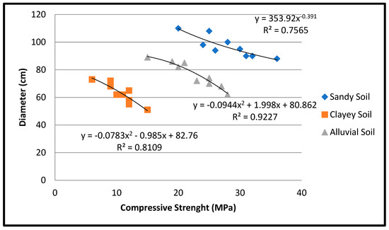
Figure 11.
Relationship between average diameters of CJG columns and UCS test results for sandy soil, clayey soil, and alluvial soil.
4. Conclusions
Nowadays, ground improvement with the jet grouting method is widely used. So far, there have not been many studies on the physical and mechanical properties of different soil types at different w/c ratios and different grouting pressures. This is thought to be because it is difficult to make in the field and then transport the columns created to the laboratory. In this study, CJG columns were produced in three different soil types (sandy soil, clay soil, and alluvial soil), three different w/c ratios (0.75, 1.00, and 1.25), and three different injection pressures (400, 450, and 500 bar). Samples were taken from each of the CJG columns from the middle, right, and left sides of the column. The physical (density, water absorption, and porosity tests) and mechanical properties (UCS and UPV tests) of the samples were analyzed and the following results were obtained:
- The strength of CJG columns in sandy soils was found between 36 and 15 MPa, between 15 and 4 MPa in clay soils, and between 32 and 15 MPa in alluvial soils. In this study, it was observed that the compressive strength of CJG columns decreased with increasing w/c ratios and increasing injection pressure. As the injection pressure increased, the compressive strength of the CJG columns decreased as more of the surrounding soil was enclosed. Sandy soils had high compressive strength as they formed a homogeneous and more solid structure.
- From the UPV test results in this study, the maximum value on sandy soils was found to be 3650 m/s and the minimum value was 2950 m/s. Also, the same was found between 2480 m/s and 1650 m/s for clayey soils and between 3420 m/s and 2750 m/s for alluvial soils. S-CJG400-0.75, S-CJG450-0.75, and S-CJG400-1.00 samples were found to have medium speed in sandy soil, while other sandy soil samples were found to have low speed. The result of UPV tests performed on CJG columns produced in clay soil was determined as very low velocity since it was less than 2500 m/s. According to the test results of CJG columns produced in alluvial soils, the UPV test result was found to be low velocity since it was between 2500 and 3500 m/s. The elastic modulus values of the CJG columns found according to the UPV test results are 0.086–0.102 MPa for sandy soils, 0.051–0.068 MPa for clayey soils, and 0.078–0.097 MPa for alluvial soils. In addition, the modulus of elasticity of the CBJ column formed in sandy soils was higher. This is because the elasticity value increases as the strength property increases.
- CJG columns in sandy soil had the highest density. The highest density value was found to be 1.75 g/cm3 and the lowest value was 1.58 g/cm3. The highest and lowest densities of alluvial and clay soils were found to be 1.62–1.40 g/cm3 and 1.32–1.03 g/cm3, respectively.
- The maximum and minimum water absorption of CJG columns formed in sandy soils were found to be 49% and 25%. The maximum–minimum values for alluvial and clayey soils were found to be 48–29% and 57–38%, respectively. In general, the water absorption of the samples taken from the center of the CJG columns is lower than the water absorption of the samples taken from the right and left sides.
- The porosity was found to be 28–50% in sandy soils, 47–61% in clay soils, and 32–49% in alluvial soils. In all three soil types, it was observed that as the w/c ratio increased and the injection pressure increased, the porosity increased. Porosity is generally directly proportional to water absorption and inversely proportional to density. So the higher the porosity, the greater the water absorption and the lower the density.
- CJG column diameters were measured in the range of 88–110 cm in sandy soils, 51–73 cm in clay soils, and 62–89 cm in alluvial soils. When the CJG column diameters were compared with constant injection pressure and increasing w/c ratios, the maximum increase was found to be 13% for sandy soils, 10% for clayey soils, and 14% for alluvial soils. The column diameters were 37% larger for sandy soils than clayey soils and 26% larger than alluvial soils at the same w/c ratio and constant injection pressure.
- The result of analysis of variance (ANOVA) presented p values < 0.05 had significant effect between average diameters of CJG columns and UCS test results. In addition, it was observed that the ANOVA R2 value of the CJG column results manufactured in clayey and alluvial soil was higher and gave more significant results than the results of the column manufactured in sandy soil.
- As a result, mixtures with a 0.75 w/c ratio formed in sandy soils gave the best results in terms of both mechanical and physical properties. For future studies, it would be useful to select a single soil type and examine its physical and mechanical properties by manufacturing CJG columns for long curing periods, especially in regions with high groundwater table.
Funding
This research received no external funding.
Data Availability Statement
Data are contained within the article.
Acknowledgments
The experimental work of this article was carried out at Kahramanmaraş Sütçü İmam University, Civil Engineering Laboratory. The author thanks the Buildings Journal for its support and the reviewers for valuable feedback.
Conflicts of Interest
The author declares no conflict of interest.
References
- Mujtaba, H.; Khalid, U.; Farooq, K.; Elahi, M.; Rehman, Z.; Shahzad, H.M. Sustainable Utilization of Powdered Glass to Improve the Mechanical Behavior of Fat Clay. KSCE J. Civ. Eng. 2020, 24, 3628–3639. [Google Scholar] [CrossRef]
- Ijaz, N.; Rehman, Z.U.; Ijaz, Z. Recycling of paper/wood industry waste for hydromechanical stability of expansive soils: A novel approach. J. Clean. Prod. 2022, 348, 131345. [Google Scholar] [CrossRef]
- Ijaz, N.; Ye, W.; Rehman, Z.U.; Dai, F.; Ijaz, Z. Numerical study on stability of lignosulphonate-based stabilized surficial layer of unsaturated expansive soil slope considering hydro-mechanical effect. Transp. Geotech. 2021, 32, 100697. [Google Scholar] [CrossRef]
- Dis, M.O. A New Approach for Completing Missing Data Series in Pan Evaporation Using Multi-Meteorologic Phenomena. Sustainability 2023, 15, 15542. [Google Scholar] [CrossRef]
- Güllü, H. On the viscous behavior of cement mixtures with clay, sand, lime and bottom ash for jet grouting. Constr. Build. Mater. 2015, 93, 891–910. [Google Scholar] [CrossRef]
- Tunar Özcan, N.; Gokceoglu, C. A Novel Approach for Assessing the Performance of Offshore Ground Improvement in Floating Storage and Regasification Unit (FSRU) Terminal Construction. Appl. Sci. 2023, 13, 9245. [Google Scholar] [CrossRef]
- Olgun, M.; Kanat, A.; Senkaya, A.; Erkan, H. Investigating the properties of jet grouting columns with fine-grained cement and silica fume. Constr. Build. Mater. 2021, 267, 120637. [Google Scholar] [CrossRef]
- Shakya, S.; Inazumi, S.; Chao, K.C.; Wong, R.K.N. Innovative Design Method of Jet Grouting Systems for Sustainable Ground Improvements. Sustainability 2023, 15, 5602. [Google Scholar] [CrossRef]
- Li, Z.; Zhao, J.; Hu, K.; Li, Y.; Liu, L. Adaptability Evaluation of Rotary Jet Grouting Pile Composite Foundation for Shallow Buried Collapsible Loess Tunnel. Appl. Sci. 2023, 13, 1570. [Google Scholar] [CrossRef]
- Gao, P.W.; Zhong, J.J.; Deng, Y.S.; Xu, X.F.; Li, M.Y.; Zhang, J. Preparation and microstructure analysis of high performance lightweight grouting materials. J. East China Jiaotong Univ. 2021, 38, 29–35. [Google Scholar]
- Mohan, M.K.; Pillai, R.G.; Santhanam, M.; Gettu, R. High-performance cementitious grout with fly ash for corrosion protection of post-tensioned concrete structures. Constr. Build. Mater. 2021, 281, 122612. [Google Scholar] [CrossRef]
- Kim, D.J.; Park, G.J.; Le, H.V.; Moon, D.Y. Fresh and hardened properties of steel fiber-reinforced grouts containing ground granulated blast-furnace slag. Constr. Build. Mater. 2016, 122, 332–342. [Google Scholar] [CrossRef]
- Çelik, F.; Canakci, H. An investigation of rheological properties of cement-based grout mixed with rice husk ash (RHA). Constr. Build. Mater. 2015, 91, 187–194. [Google Scholar] [CrossRef]
- Sonebi, M.; Perrot, A. Effect of mix proportions on rheology and permeability of cement grouts containing viscosity modifying admixture. Constr. Build. Mater. 2019, 212, 687–697. [Google Scholar] [CrossRef]
- Çınar, M.; Karpuzcu, M.; Çanakcı, H. Effect of waste marble powder and fly ash on the rheological characteristics of cement based grout. Civ. Eng. J. 2019, 5, 777–788. [Google Scholar] [CrossRef]
- Qian, X.; Zhang, P.; Wang, S.; Guo, S.; Hou, X. Grouting Additives and Information-Based Construction of Jet Grouting in the Water-Rich Sand Stratum. Appl. Sci. 2022, 12, 12586. [Google Scholar] [CrossRef]
- Çınar, M.; Karpuzcu, M.; Çanakçı, H. The measurement of fresh properties of cement-based grout containing waste marble powder. Measurement 2019, 150, 106833. [Google Scholar] [CrossRef]
- Çelik, F.; Akcuru, O. Rheological and workability effects of bottom ash usage as a mineral additive on the cement based permeation grouting method. Constr. Build. Mater. 2020, 263, 120186. [Google Scholar] [CrossRef]
- Seiphoori, A.; Zamanian, M. Improving mechanical behavior of collapsible soils by grouting clay nanoparticles. Eng. Geol. 2022, 298, 106538. [Google Scholar] [CrossRef]
- Nagaraju, T.V.; Venkata Rao, M.; Sunil, B.M.; Chaudhary, B. Stabilization of Expansive Clays: A Micro-mechanistic Study. In Proceedings of the International Conference on Trends and Recent Advances in Civil Engineering, Noida, India, 20–21 August 2022; Springer Nature: Singapore, 2022. [Google Scholar]
- Güllü, H. A novel approach to prediction of rheological characteristics of jet grout cement mixtures via genetic expression programming. Neural Comput. Appl. 2017, 28, 407–420. [Google Scholar] [CrossRef]
- Liu, D.; Xie, W.; Gao, J.; Hu, S.; Chen, M.; Li, Y.; Li, L. Study on the Construction Method and Effects of Ipsilateral, Multi-Nozzle, High-Pressure Jet Grouting Cut-Off Wall. Sustainability 2022, 14, 10383. [Google Scholar] [CrossRef]
- Güllü, H. A new prediction method for the rheological behavior of grout with bottom ash for jet grouting columns. Soils Found. 2017, 57, 384–396. [Google Scholar] [CrossRef]
- Canakci, H.; Güllü, H.; Dwle, M.I.K. Effect of Glass Powder Added Grout for Deep Mixing of Marginal Sand with Clay. Arab. J. Sci. Eng. 2018, 43, 1583–1595. [Google Scholar] [CrossRef]
- Hasan, M.F.; Canakci, H. Physical-mechanical assessment of full-scale soil-cement column constructed in clayey soil. Case Stud. Constr. Mater. 2022, 16, e00943. [Google Scholar] [CrossRef]
- ASTM C136/C136M; Standard Test Method for Sieve Analysis of Fine and Coarse Aggregates. ASTM International: West Conshohocken, PA, USA, 2019.
- ASTM D7928; Standard Test Method for Particle Size Distribution (Gradation) of Fine-Grained Soils Using the Sedimentation (Hydrometer) Analysis. ASTM International: West Conshohocken, PA, USA, 2017.
- ASTM C 150/C 150M; Standard Specification for Portland Cement—Type I. 1. ASTM International: West Conshohocken, PA, USA, 2021.
- ASTM D2166, 2166; Standard Test Method for Unconfined Compressive Strength of Cohesive Soil. ASTM International: West Conshohocken, PA, USA, 2016.
- ASTM C. 597; Standard Test Method for Pulse Velocity through Concrete. ASTM International: West Conshohocken, PA, USA, 2009.
- ASTM C20-00; Standard Test Methods for Apparent Porosity, Water Absorption, Apparent Specific Gravity, and Bulk Density of Burned Refractory Brick and Shapes by Boiling Water. ASTM International: West Conshohocken, PA, USA, 2000.
- Akin, M.K. Experimental studies on the physico-mechanical properties of jet-grout columns in sandy and silty soils. J. Afr. Earth Sci. 2016, 116, 190–197. [Google Scholar] [CrossRef]
- Çelik, F.; Çınar, M.; Akcuru, O. Utilization of waste bottom ash as mineral additive with partial replacement of cement in geotechnical grouting works based on mechanical features. Arab. J. Geosci. 2022, 15, 1290. [Google Scholar] [CrossRef]
- Croce, P.; Flora, A. Analysis of single-fluid jet grouting. Géotechnique 2000, 50, 739–748. [Google Scholar] [CrossRef]
- Inazumi, S.; Shakya, S.; Komaki, T.; Nakanishi, Y. Numerical Analysis on Performance of the Middle-Pressure Jet Grouting Method for Ground Improvement. Geosciences 2021, 11, 313. [Google Scholar] [CrossRef]
- Erol, A.E.; Akgonen, A.I. Investigation on behavior and seismic performance of Kaiser moment connections. KSU J. Eng. Sci. 2023, 26, 213–232. [Google Scholar] [CrossRef]
- ASTM D6473; Standard Test Method for Specific Gravity and Absorption of Rock for Erosion Control. ASTM International: West Conshohocken, PA, USA, 2015.
- Croce, P.; Flora, A.; Modoni, G. Jet Grouting: Technology, Design and Control; CRC Press: Boca Raton, FL, USA, 2014. [Google Scholar]
- Çınar, M.; Çelik, F.; Çanakcı, H.; Nassani, D.E. Fresh properties of cementitious grout with rice husk powder. Arab. J. Sci. Eng. 2017, 42, 3819–3827. [Google Scholar] [CrossRef]
Disclaimer/Publisher’s Note: The statements, opinions and data contained in all publications are solely those of the individual author(s) and contributor(s) and not of MDPI and/or the editor(s). MDPI and/or the editor(s) disclaim responsibility for any injury to people or property resulting from any ideas, methods, instructions or products referred to in the content. |
© 2023 by the author. Licensee MDPI, Basel, Switzerland. This article is an open access article distributed under the terms and conditions of the Creative Commons Attribution (CC BY) license (https://creativecommons.org/licenses/by/4.0/).