Abstract
Recent advancements in sensor technology have led to an increase in embedding sensors into construction materials for monitoring purposes in the construction industry. However, systematic research on the resulting changes to the material properties is still lacking. A previous study confirmed that the copper–nickel-plated housing of SHT-31 sensors affects the compressive strength of mortar. Moreover, it is necessary to conduct further research to determine if this analogous occurrence takes place in concrete. This study embedded temperature–humidity sensor housings in concrete at 10 mm, 20 mm, and 30 mm, before performing compression tests and a finite element analysis (FEA). The empirical findings indicate that the compressive strengths of concrete at 10 mm, 20 mm, and 30 mm depths were 26.1 MPa, 28.4 MPa, and 29.4 MPa, respectively. In contrast, the control concrete that did not have a sensor housing had a compressive strength of 31.9 MPa. In the case of mortar, a design strength of 28 MPa was achieved at a depth greater than 30 mm, while concrete reached this design strength at 20 mm. Based on these findings, embedding temperature–humidity sensor housings in concrete is recommended at depths greater than 20 mm from the surface. These results serve as important reference data for determining the optimal embedding depth of sensor housings in structures using cement-based materials.
1. Introduction
1.1. Backgrounds
The construction industry has undergone continuous development over the past several decades. One driving force behind this growth has been the digitization and scientific innovation of the modern age [1]. These factors have radically transformed the construction processes, offering new directions in efficiency and safety. The core technological component of this advancement is the Internet of Things (IoT) [2]. Utilizing IoT technology stems from its crucial role in the paradigm of smart construction, where the monitoring of structural conditions and preventative maintenance are prioritized [3]. At the heart of the IoT are sensor technologies used explicitly for real-time detection and the analysis of changes within construction materials such as concrete and mortar [4]. Integrated IoT technology involving embedded sensors, communication networks, and data analytics quickly detects the need for structural condition assessments and preventative maintenance [5].
Merzbacher et al. [6] investigated a method for detecting deformations caused by various factors such as load, temperature, and vibration by embedding optical fiber sensors within concrete structures. Using fiber optic refractive index sensors, they measured deformations in concrete structures and found that optical fiber sensors offered higher accuracy and reliability than traditional metal sensors. However, the authors mentioned uncertainties regarding these sensors’ durability and long-term stability. Quinn et al. [7] developed an embedded wireless sensing system to observe concrete curing and monitor its structural integrity. The proposed system combines electromechanical impedance methods with wireless sensing technology and has been confirmed to monitor the development of concrete strength accurately. Ekaputri et al. [8] embedded humidity sensors in BFS mortars to measure the internal relative humidity. Comparative experiments were conducted by embedding sensors in typical Portland cement mortar and 40% BFS replacement mortar. These experiments showed a higher decrease in internal relative humidity when BFS was applied, and the pore structure, initial hydration products, and slag content in OPC mortar with BFS were considered key factors. Zhou et al. [9] developed a method to monitor crack propagation in mortar using acoustic emission (AE) signals by embedding cement-based piezoelectric ceramic sensors in concrete. They introduced an AE energy index for assessing the energy released by cracks during loading, demonstrating the feasibility of real-time crack propagation monitoring using piezoelectric ceramic sensors embedded in cement-based materials. Pan and Huang [10] crafted a piezoelectric cement sensor leveraging electromechanical impedance (EMI) technology to keep tabs on mortar strength. They incorporated PEC along with PZT sensors within mortar samples and continuously monitored the compressive strength over a period of 56 days. The outcome delineated the observation that the efficacy of the PEC sensor is parallel with that of the PZT sensor, although the PEC sensor was adjudged superior owing to more pronounced alterations in electrical impedance.
Previous research has demonstrated the ability to accurately monitor changes in the physical properties of concrete and mortar using sensor technology. However, studies are relatively scarce on the impact and behavior of sensor housings when embedded in these materials. Concrete and mortar serve as essential construction materials used for structural frameworks, finishing materials, and road paving [11]. The physical properties of each material significantly influence the overall safety and durability of a structure [12]. Although both concrete and mortar consist of cement, water, and sand as their basic components, concrete includes gravel to enhance its strength, while mortar utilizes varying ratios of cement to sand to increase its viscosity [13]. These physical differences could act as important variables in sensor housing placement and the subsequent impact assessment. Despite the potential for the presence of sensor housings to influence compressive strength, thus directly affecting overall structural safety, research on this aspect remains limited.
1.2. Previous Study
Considering the importance of sensor technology, as verified in previous research, and the need for more research on the influence of sensor housings on concrete and mortar, the research team initially focused on mortar. Mortar is made of relatively simple components, making it suitable as an initial model for analyzing the effects of sensor housings. Accordingly, a previous study investigated the placement and impact of sensor housings made of copper–nickel-plated within mortar.
Kim et al. [14] centered their research on the impact of the housing’s placement on the strength of mortar under compression. Their objective was to elucidate how sensor housing depth can affect mortar compressive strength. Experiments were conducted using compression strength tests and a finite element analysis (FEA) at various depths. The results showed that the deeper the housing, the higher the compressive strength. In particular, samples at a 10 mm depth showed more than twice the average compressive strength compared to those at a 5 mm depth. Another significant result was that the mortar samples without a sensor housing had the highest compressive strength, emphasizing the substantial influence of sensor housing placement on compressive strength. Cracks also occurred at the interface between the two materials due to a significant difference in their elastic moduli. Using their experimental results and an FEA, the team proposed a predictive equation for mortar compressive strength based on sensor housing depth. This equation allows for the prediction of compressive strength when a copper–nickel-plated surface sensor housing is embedded in a cementitious mortar. The research findings indicated that the desired compressive strength of the mortar structure is achieved when the housing depth is a minimum of 30 mm.
Although this research provides a foundation for future studies, verification is needed to determine whether the same results apply to concrete. Currently, while sensor-based monitoring of concrete and mortar is widely used, no comparative studies have explored the effects of sensor housings on these materials; therefore, this research aims to fill the gap by investigating the effects of sensor housings on the compressive strength of concrete and mortar.
1.3. Research Objective
Consequently, the primary objective of this research is to delve into the impacts of material property variances on the location of sensor housings embedded within concrete and mortar. Special attention is given to the manifestations of strength in both materials. Previous studies have predominantly focused on mortar. In light of this, our research juxtaposes these earlier findings with current results, emphasizing the specific influence of material distinctions on compressive strength. Through this analysis, the researchers aim to clarify how compressive strength varies according to the placement of embedded sensor housings in both mortar and concrete. Based on the findings, a rationale for sensor housing placement in each material is presented. Subsequently, this research seeks to examine and evaluate how the presence of embedded sensor housings impacts the strength of both concrete and mortar using a detailed investigative method. Through this, an exploration of the optimal housing placement to secure the planned compressive strength in each material is sought. Moreover, utilizing a numerical analysis to validate the experimental results and providing foundational data for sustainable structural stability when embedding sensor housings in structures composed of concrete or mortar is the aim. Ultimately, the derived optimal housing placement is anticipated to contribute to enhancing structural stability, bearing significant implications for more effective and safer structural design and management.
2. Materials and Methods
2.1. Concrete Sample Preparation
According to ASTM C 928 [15], cementitious mortar or concrete for repairs should exhibit a minimum compressive strength of 28 MPa after 28 days. Accordingly, the design strength of the concrete in this study was planned to be at least 28 MPa to be consistent with the mortar tests. While samples used for concrete compressive strength tests generally follow the cylindrical shape specified by ASTM 39 [16], this study aimed to manufacture samples in a cubic shape identical to that used for mortar compressive strength tests. ASTM does not provide specifications for cubic-shaped concrete samples, so BS 1881-116 [17] and BS EN 12390-3 [18] are referred to for manufacturing the samples. The mix ratio for the samples was set at 1:2:4:0.6 (cement/sand/gravel/water), and the maximum size of the gravel was set at 25 mm. The remaining conditions were kept consistent with those for mortar sample preparation, with mixing carried out using a mixer following ASTM C305 [19].
2.2. Sensor Instrumentation and Sample Size Configuration
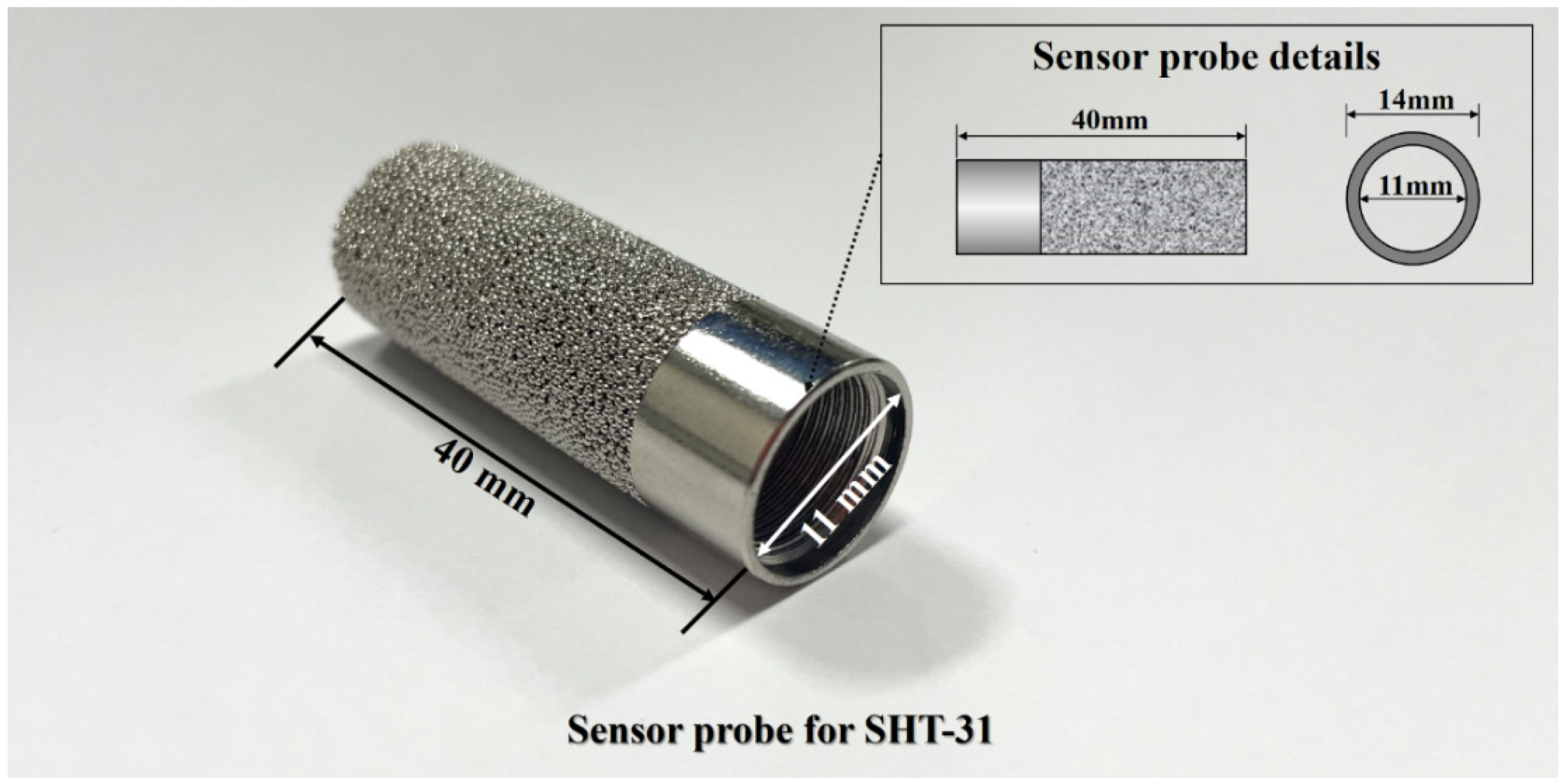
As observed in a previous study, the location of sensor housings can significantly impact the compressive strength of mortar; however, the effect may differ in the case of concrete. To test this, the study investigates the influence that varying the embedding depth of sensor housings relative to the concrete cover thickness has on compressive strength. The experiments were conducted to identify a sensor housing location that adheres to the necessary compressive strength requirements. The sensor utilized in this study was the SHT-31 humidity and temperature sensor manufactured [20] by the same model used in the preceding research. Recognized for its precision and reliability, the SHT-31 has been widely employed across multiple sectors. In building automation systems, the sensor assists in maintaining optimal environmental conditions through air quality monitoring, ensuring efficient energy consumption [21]. It also finds utility in agriculture, optimizing growth conditions for crops [22], and plays a pivotal role in public infrastructure safety monitoring [23]. Such applications emphasize their potential to provide real-time insights, preemptively identify anomalies, and facilitate immediate responses. The housing specifications for this sensor are shown in Figure 1, with dimensions of 40 mm in length, 14 mm for the external diameter, and 11 mm for the internal diameter.
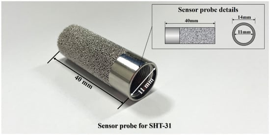
Figure 1.
SHT-31 sensor housing specifications.
For embedding the sensor housings, concrete samples were manufactured in a cubic shape with a 150 mm width, length, and height. The embedding depth of the sensor housings was set at 10 mm intervals from the surface, and experiments were conducted for three cases, at depths of 10 mm, 20 mm, and 30 mm, to maintain consistency. While previous research embedded sensor housings at 5 mm intervals in mortar samples, the concrete samples in this study are three times larger than the mortar samples and contain gravel. Therefore, precise adjustment at 5 mm intervals proved challenging, leading to the decision to set the sensor housing embedding intervals at 10 mm.
2.3. Production of Test Samples
The previous study speculated that the influence of the placement of the sensor housing on the compressive strength would be less significant in concrete due to its broader structure compared to mortar. Sensor housings were embedded in concrete samples at different depths during casting, followed by a curing process for validation. However, challenges may arise during the embedding process; the sensor housing may tilt due to coarse aggregates, or its position may change due to its weight during curing. To address this, rods and molds were designed to secure the sensor housing in the concrete samples, preventing movement during the curing period.
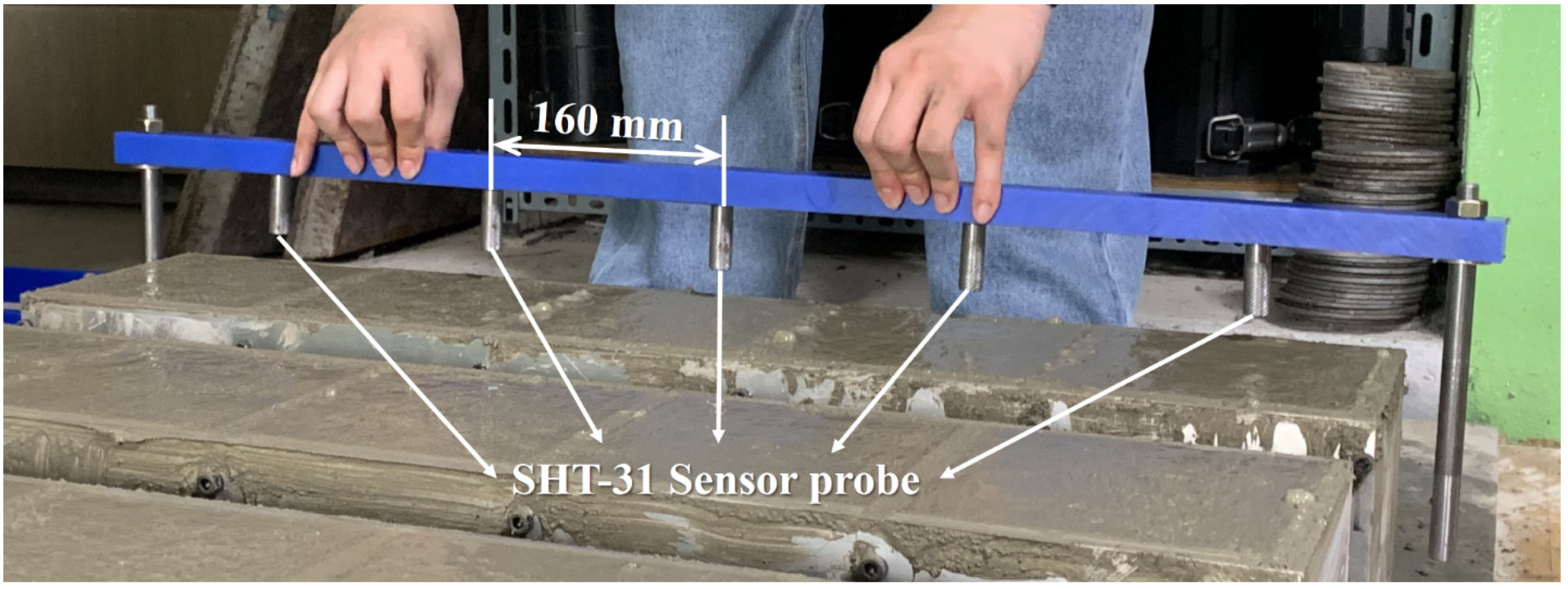
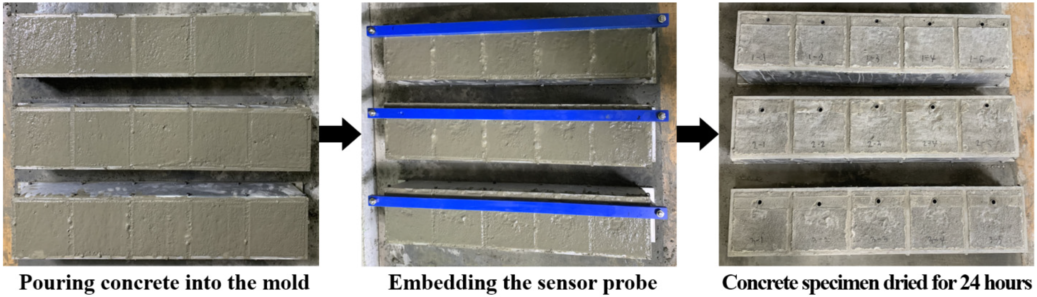
The sensor housing used is made of a copper–nickel-plated material. Although copper is non-magnetic [24], the nickel plating gives the housing magnetic properties [25]; therefore, rods were designed to hold the sensor housings at the predetermined embedding depths via magnets, as depicted in Figure 2. Then, 10 mm-diameter magnets were positioned at 160 mm intervals on the rod. This arrangement ensured a secure attachment of the housings to the rods, preventing any movement within the mortar during the curing process. After 24 h of curing, the rods were detached from the concrete, leaving only the sensor housings embedded at consistent intervals. The process of sample manufacturing is illustrated in Figure 3.

Figure 2.
Sensor housing embedding method.
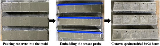
Figure 3.
Concrete compressive strength sample preparation process.
The samples underwent a wet curing process at a temperature range of 23 °C ± 2 °C for 28 days following ASTM C511 [26]. The compressive strength tests were conducted using a digital compressive material tester, the HCT-DH 200 from Heungjin, the same tester used in the mortar compressive strength experiments [27].
3. Finite Element Analysis
The structural integrity of concrete samples with embedded sensor housings was investigated through a numerical approach known as a finite element analysis (FEA). The investigation focused on how the depth of the sensor within the sample influenced its behavior. The software employed for these simulations was ABAQUS 2022, a well-regarded commercial FE software chosen for its capacity to deliver reliable, precise, and robust solutions in addressing non-linear challenges. The ABAQUS software’s concrete damage plasticity model was utilized to mimic the plastic-damage behavior of quasi-brittle materials, including concrete. This model is drawn from Lubliner et al. [28] and has been adapted based on the research of Lee and Fenves [29], thus serving as an appropriate library to simulate plastic-damage responses.
In this model, the stress–strain relationship is given by
where , , , and denote the Cauchy stress, total strain, plastic strain, and elastic stiffness of undamaged material, respectively. corresponds to a scalar damage parameter that varies between zero (indicating an undamaged state) and one (indicating complete damage).
The dissimilarity in stress–strain behavior between compression and tension in concrete is well recognized, leading to distinct patterns of elastic stiffness degradation due to damage in these two modes. The deterioration responses in compression and tension are described by separate damage factors: for compression and for tension. When confronted with a general scenario involving multiaxial loading, ABAQUS employs the following equation:
where and represent the scalar stiffness recovery parameters for compression and tension, respectively.
In this work, the following yield function is employed (Lubliner et al. [28], Lee and Fenves [29]):
where denotes the Mises effective stress, given as (: the effective stress tensor shear component, ), and denotes the effective hydrostatic pressure, given as (: the identity tensor). represents the Macauley bracket; denotes the algebraically maximum eigenvalue of ; and denotes the effective compressive cohesion stress. The parameter is a function of and (the effective tensile cohesion stress) and is defined as follows:
where the coefficient is given by
where denotes the uniaxial compressive strength and denotes the biaxial compressive strength. In general, the ratio falls between and , leading to a range of values from to .
The coefficient comes into effect exclusively when (triaxial compression) is less than zero. This coefficient is given as follows:
where represents the ratio between the tensile and compressive meridians.
To define plastic flow, the non-associated potential flow rule is utilized in this work.
where and denote the flow potential and non-negative plastic multiplier, respectively. In this study, the Drucker–Prager hyperbolic function is employed as the flow potential:
where denotes the measured dilation angle within the p − q plane under significant confining pressure, represents the failure stress under uniaxial tension, and stands for an eccentricity-related parameter.
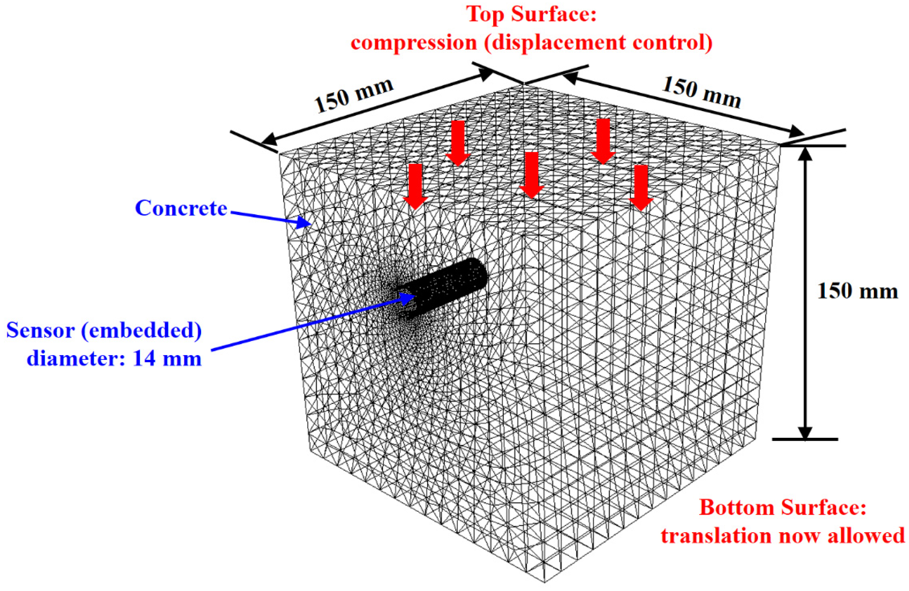
In this study, the damage-plasticity behavior of concrete samples with embedded sensor housings was analyzed by simulation as a function of the sensor housing embedment depth. The material constants of the concrete and the sensor housing used in the simulation are given in Table 1. The sensor housing’s material properties were considered to be similar to those of a copper–nickel alloy, and data regarding the sensor housing’s material attributes were extracted from Mat-Web: Online Materials Information Resource [30]. The material constants for concrete were taken from [31]. Ten-node quadratic tetrahedral (C3D10) elements were used for both the concrete and the sensor housing, with 87,796 elements and 104 elements for the concrete and sensor housing, respectively. The boundary conditions were set to prevent deformation on the bottom surface, with the specifics depicted in Figure 4.

Table 1.
Concrete and sensor housing properties.
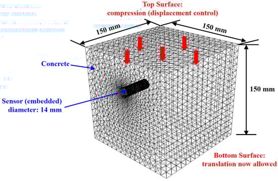
Figure 4.
Schematic illustration of the finite element analysis model, including dimensions, boundary conditions, loading conditions, and mesh configurations.
4. Results and Discussion
Compressive strength tests were conducted on three samples per housing location for each cover thickness, and the images taken during these tests are illustrated in Figure 5.
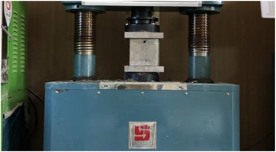
Figure 5.
Concrete compression test.
Table 2 offers a summary of the compressive strength test results, which are organized based on the depth at which each sensor housing was positioned, and it also includes the results for the control samples without any sensor housings embedded. The data reveal that at a depth of 10 mm, the average compressive strength is 26.1 MPa, while at 20 mm, it increases to 28.4 MPa, and at 30 mm, it increases to 29.4 MPa at a 30 mm depth. On the contrary, the control samples, devoid of embedded sensor housings, demonstrated a peak average compressive strength of 31.9 MPa. This signifies a decline in strength as the sensor housings are situated nearer to the surface. The observed standard deviations (SDs) stood at 0.55 MPa for 10 mm, 0.51 MPa for 20 mm, and 0.79 MPa for 30 mm, in comparison to the control samples, which had an SD of 0.53 MPa. From these experimental findings, it is inferred that to uphold consistent structural stability by incorporating temperature–humidity sensor housings, embedding them at the smallest distance of 20 mm from the concrete’s upper face is necessary to achieve the designated strength or higher.
Table 2.
Results of concrete compressive strength test.
Contours representing the scalar compressive damage parameter, (referred to as DAMAGEC within ABAQUS), are shown in Figure 6 for various sensor housing embedment depths in the mortar and concrete samples. A value of 0 signifies an undamaged material state. The sensor housing areas were set to be invisible in the figure for clarity. However, identical sensor housings were embedded in mortar and concrete at depths of 10 mm, 20 mm, and 30 mm. In the previous study, a sensor housing with an external diameter of 14 mm and a length of 40 mm was embedded in a 50 mm3 cube-shaped mortar sample. In Figure 6, is shown as a color spectrum from blue ( close to 0) to red ( close to 1). This result is likely due to the significant volume occupied by the sensor housing within the mortar sample. Conversely, in a 150 mm3 cube-shaped concrete sample with the same size as the embedded sensor housing, the FE analysis showed values within a 0.6 range, indicating relatively low compressive damage. These results suggest that, in comparison to mortar, the impact of sensor housings on the strength of concrete is negligible.
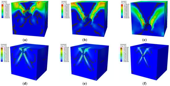
Figure 6.
Contours showing the compressive damage factor () for various embedment depths: (a) 10 mm in mortar, (b) 20 mm in mortar, (c) 30 mm in mortar, (d) 10 mm in concrete, (e) 20 mm in concrete, and (f) 30 mm in concrete.
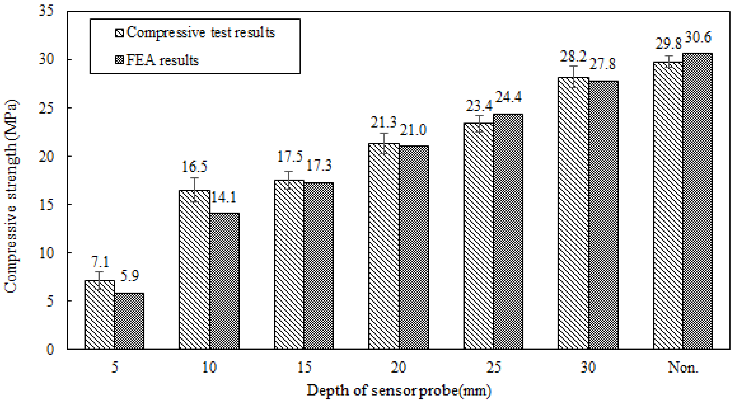
Figure 7 portrays the mortar sample’s compressive strength from the preceding research and the finite element analysis (FEA) outcomes. Compressive strength assessments were carried out on mortar samples with sensor housings embedded at depths from 5 mm to 30 mm in 5 mm steps to discern the effect of sensor housing embedding at varying depths. The obtained experimental findings affirmed that a deeper sensor housing embedding led to enhanced compressive strength. This trend was also mirrored in the FEA results, thus supporting the validity of the experimental observations.
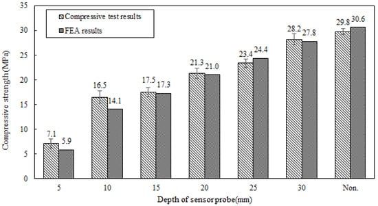
Figure 7.
Comparison of results between the mortar’s compressive strength and finite element analysis [14].
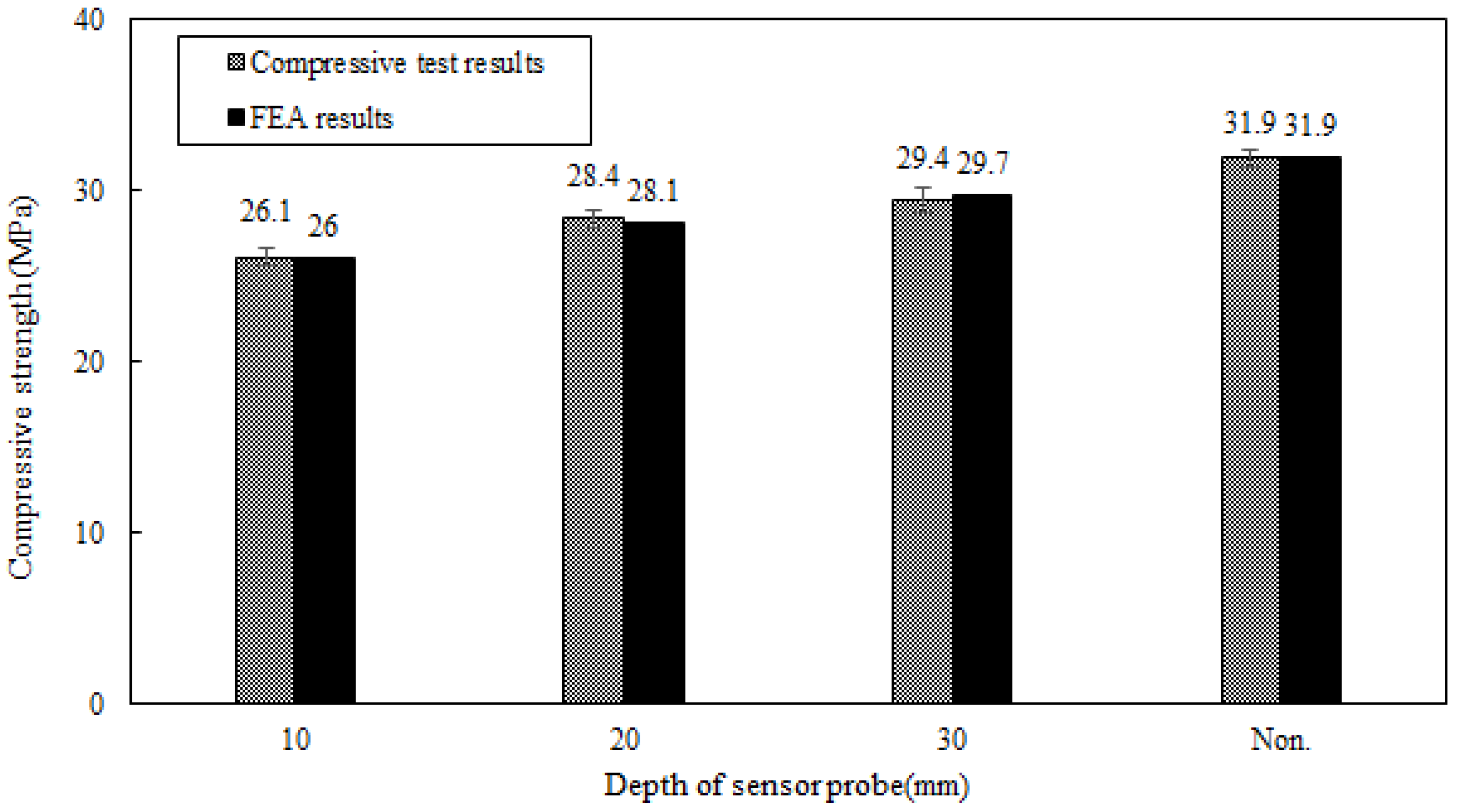
Figure 8 shows the concrete compressive strength in this research alongside the findings from the FEA. Due to the larger size of the concrete samples compared to the mortar samples and the presence of gravel, which makes fine adjustment challenging, the depths were set at 10 mm intervals. Samples with depths of 10 mm, 20 mm, and 30 mm were prepared for testing. The experimental results confirmed that, similar to the mortar samples, the concrete compressive strength also increased as the depth of the sensor housing from the surface increased. The FEA likewise reflected this trend well.
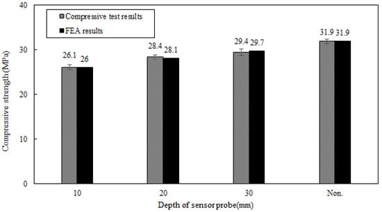
Figure 8.
Comparison of results between the concrete’s compressive strength and finite element analysis.
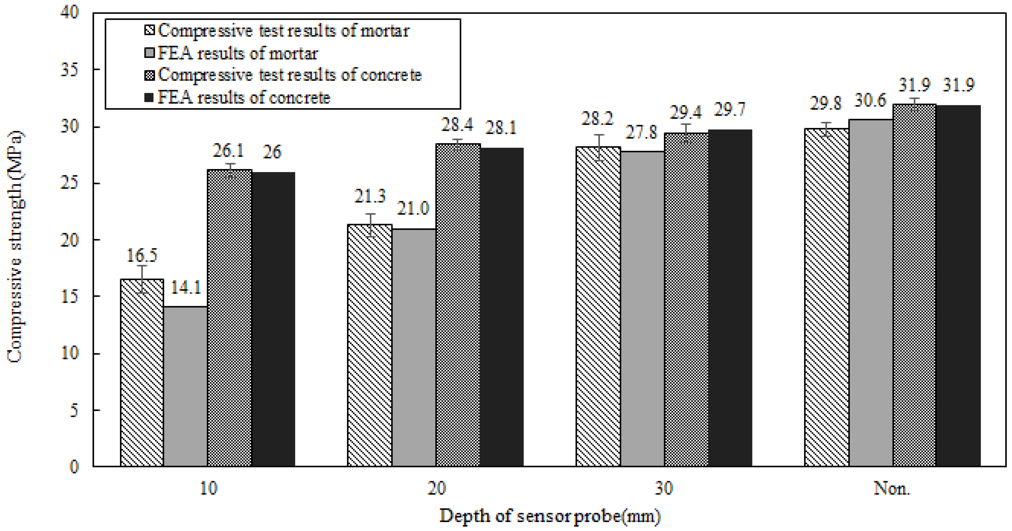
Figure 9 is a bar graph comparing the compressive strength test results and FEA results for mortar and concrete. Both materials confirmed that the greater the depth of the sensor housing, the greater the compressive strength. However, concrete showed a relatively higher compressive strength at the 10 mm and 20 mm depths than mortar. This difference is attributed to the material properties of concrete and mortar. Concrete typically contains gravel, contributing to a higher compressive strength than mortar; therefore, the decrease in compressive strength when the sensor is embedded closer to the surface is less sensitive in concrete than in mortar. Moreover, the larger size of the concrete sample compared to mortar allows for a more distributed influence of the sensor housing, possibly minimizing its impact on compressive strength. The FEA also reflected these material differences well, providing validation for the experimental results.
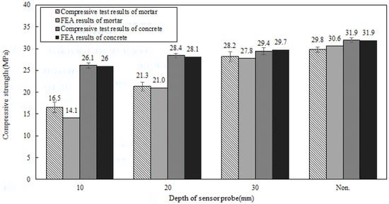
Figure 9.
Contrast between the compressive strength test results and the numerical analysis.
The key difference between this study and preceding research lies in the materials used and the resultant strength outcomes concerning the embedding depth of sensor housings. In a previous study, the mortar used achieved the planned strength at embedding depths greater than 30 mm. In contrast, the concrete used in this study already met the planned strength at depths greater than 20 mm. This difference stems from the material properties and characteristics of mortar and concrete.
For all the embedment depths, damage occurred diagonally from the position of the sensor housing. This can be seen as two X-shaped shear bands forming, which is a typical occurrence of shear bands. Shear bands, or strain localization, are narrow regions of strong shear strain that occur while the material is undergoing plastic deformation [32]. In Figure 2, the blue area outside the shear band is in the elastic region. The shear banding phenomenon is important for understanding the failure of quasi-brittle materials like concrete because the extreme plastic deformation occurring within the shear band eventually leads to the damage and failure of the material. The experiments and simulations confirm that the samples’ fracture geometry and failure mode are in the form of shear bands.
Both mortar and concrete are critically used in the construction industry, serving distinct purposes and applications. Mortar is primarily used for small-scale repair sites, meaning the scope of influence from embedded sensor housings is relatively small. Conversely, concrete is used in large structures such as bridges and large buildings. As a result, a same-sized sensor housing can have a minimal impact on the overall structure when embedded in concrete. Therefore, when applying embedded sensor housings to large structures, it is expected that they will have an insignificant effect on the quality and performance of the structure.
Based on this research, future studies should examine the impact of the thermal expansion coefficient difference between the copper–nickel alloy of sensor housings and concrete mortar on crack formation during freeze–thaw cycles. Additionally, research on the long-term stability of the sensor, its performance under extreme environmental conditions, and its compatibility with various construction materials is warranted. Exploring methods to enhance the sensor’s sensitivity and efficiency can also be viewed as a crucial direction for upcoming research endeavors in the realm of automation in construction.
5. Conclusions
This study compared and analyzed the impact of sensor housing burial depth on the compressive strength of concrete relative to a previous study. The significant findings are summarized as follows.
- Mortar and concrete exhibit different material characteristics, resulting in different compressive strengths at the same burial depth. The compression test indicated that the mortar strength increased as the sensor housing’s embedment depth increased and reached the desired strength at a burial depth of 30 mm. In comparison, the concrete already exhibited high compressive strength at a depth of 10 mm. Based on this, it is recommended that sensor housings be embedded within concrete at least 20 mm away from the concrete surface.
- Initial cracks were observed where the sensor housing was located, and the shape of these cracks spreading around the housing was captured. This was also observed in the mortar and is presumed to be due to stress concentration at the interface between the sensor housing and the concrete. These findings indicate that the initiation and spread of cracks may differ depending on the placement of the sensor;
- Additionally, the study analyzed the damage patterns after embedding sensor housings in mortar and concrete samples. The results confirmed the formation of shear bands in diagonal directions at all burial depths, allowing the failure patterns in the sample to be identified in relation to material ductility and fracture mechanisms;
- Both mortar and concrete are crucially used in the construction industry, but they serve different purposes and have different scopes of application. Mortar is primarily used for small-scale repair work, and the impact of sensor housings is relatively limited in these cases. Conversely, concrete is employed in large structures; therefore, the influence of sensor housings is expected to be minimal compared to the overall structure.
The study’s findings significantly contribute to a deeper understanding of how the embedment depth of sensor housings affects the strength of mortar and concrete in the construction field. This can serve as foundational data for determining the optimal burial depth of sensor housings under various materials and conditions. These research outcomes are expected to serve as a valuable reference for effectively integrating sensors while ensuring the sustainable structural stability of structures.
Author Contributions
Conceptualization, J.Y.; methodology, H.K.; software, Y.S.; validation, H.K.; formal analysis, Y.S. and C.K.; investigation, C.K.; resources, C.K. and J.C.; data curation, J.C.; writing—original draft preparation, C.K.; writing—review and editing, J.Y.; visualization, Y.S.; supervision, J.Y.; project administration, J.Y.; funding acquisition, J.Y. All authors have read and agreed to the published version of the manuscript.
Funding
This study was supported by The National Research Foundation of Korea (NRF) grant funded by the Korea government (MSIT) (No. 2021R1F1A10606851222182102130102).
Institutional Review Board Statement
Not applicable.
Informed Consent Statement
Not applicable.
Data Availability Statement
The data that support the findings of this study are available on request from the authors.
Acknowledgments
This research was conducted with the technical support of Geumgang Remi-con, a limited partnership based in Jecheon, Chungcheongbuk-do, Republic of Korea.
Conflicts of Interest
The authors declare no conflict of interest.
References
- Musarat, M.A.; Hameed, N.; Altaf, M.; Alaloul, W.S.; Al Salaheen, M.; Alawag, A.M. Digital Transformation of the Construction Industry: A Review. In Proceedings of the 2021 International Conference on Decision Aid Sciences and Application (DASA), Sakheer, Bahrain, 7–8 December 2021; pp. 897–902. [Google Scholar] [CrossRef]
- Štefanič, M.; Stankovski, V. A review of technologies and applications for smart construction. Proc. Inst. Civ. Eng. Civ. Eng. 2018, 172, 83–87. [Google Scholar] [CrossRef]
- Scuro, C.; Sciammarella, P.F.; Lamonaca, F.; Olivito, R.S.; Carni, D.L. IoT for structural health monitoring. IEEE Instrum. Meas. Mag. 2018, 21, 4–14. [Google Scholar] [CrossRef]
- Wang, M.L.; Lynch, J.P.; Sohn, H. Introduction to sensing for structural performance assessment and health monitoring. In Sensor Technologies for Civil Infrastructures: Sensing Hardware and Data Collection Methods for Performance Assessment; Woodhead: Cambridge, UK, 2014; pp. 57–264. [Google Scholar]
- Lamonaca, F.; Sciammarella, P.; Scuro, C.; Carni, D.; Olivito, R. Internet of things for structural health monitoring. In Proceedings of the 2018 Workshop on Metrology for Industry 4.0 and IoT, Brescia, Italy, 16–18 April 2018; pp. 95–100. [Google Scholar] [CrossRef]
- Merzbacher, C.; Kersey, A.D.; Friebele, E. Fiber optic sensors in concrete structures: A review. Smart Mater. Struct. 1996, 5, 196–208. [Google Scholar] [CrossRef]
- Quinn, W.; Kelly, G.; Barrett, J. Development of an embedded wireless sensing system for the monitoring of concrete. Struct. Health Monit. 2012, 11, 381–392. [Google Scholar] [CrossRef]
- Ekaputri, J.J.; Maekawa, K.; Ishida, T. Experimental study on internal RH of BFS mortars at early age. Mater. Sci. Forum 2016, 857, 305–310. [Google Scholar] [CrossRef]
- Zhou, H.; Liu, Y.; Lu, Y.; Dong, P.; Guo, B.; Ding, W.; Xing, F.; Liu, T.; Dong, B. In-situ crack propagation monitoring in mortar embedded with cement-based piezoelectric ceramic sensors. Constr. Build. Mater. 2016, 126, 361–368. [Google Scholar] [CrossRef]
- Pan, H.H.; Huang, M.-W. Piezoelectric cement sensor-based electromechanical impedance technique for the strength monitoring of cement mortar. Constr. Build. Mater. 2020, 254, 119307. [Google Scholar] [CrossRef]
- Kosmatka, S.H.; Panarese, W.C.; Kerkhoff, B. Design and Control of Concrete Mixtures; PCA: Warsaw, Poland, 2009. [Google Scholar]
- Mehta, P.K.; Monteiro, P.J. Concrete: Microstructure, Properties, and Materials, 4th ed.; McGraw-Hill: New York, NY, USA, 2005. [Google Scholar]
- Powers, T.C. The Properties of Fresh Concrete; Wiley: New York, NY, USA, 1968. [Google Scholar]
- Kim, C.; Song, Y.; Cho, J.; Kang, J.; Yeon, J. Effect of Embedded Depth of Copper-Nickel-Plated Sensor Probes on Compressive Strength Development of Mortar. Sustainability 2023, 15, 10772. [Google Scholar] [CrossRef]
- ASTM C928/928M-20a; Standard Specification for Packaged, Dry, Rapid-Hardening Cementitious Materials for Concrete Repairs. ASTM International: West Conshohocken, PA, USA, 2020.
- ASTM C39/39M-21; Standard Test Method for Compressive Strength of Cylindrical Concrete Specimens. ASTM Internationa: West Conshohocken, PA, USA, 2021.
- BS 1881-116; Method for Determination of Compressive Strength of Concrete Cubes. BSI: London, UK, 1983.
- BS EN 12390-3; Testing Hardened Concrete-Part 3: Compressive Strength of Test Specimens. BSI: London, UK, 2002.
- ASTM C305-21; Standard Practice for Mechanical Mixing of Hydraulic Cement Pastes and Mortars of Plastic Consistency. ASTM International: West Conshohocken, PA, USA, 2021.
- Sensirion. Available online: https://www.sensirion.com/ (accessed on 31 August 2023).
- Demanega, I.; Mujan, I.; Singer, B.; Andelković, A.; Babich, F.; Lucina, D. Performance assessment of low-cost environmental monitors and single sensors under variable indoor air quality and thermal conditions. Build. Environ. 2021, 187, 107415. [Google Scholar] [CrossRef]
- McCauley, D.; Nackley, L.; Kelley, J. Demonstration of a low-cost and open-source platform for on-farm monitoring and decision support. Comput. Electron. Agric. 2021, 187, 106284. [Google Scholar] [CrossRef]
- Khoa, T.A.; Lam, P.D.; Nam, N.H. An efficient energy measurement system based on the TOF sensor for structural crack monitoring in architecture. J. Inf. Telecommun. 2023, 7, 56–72. [Google Scholar] [CrossRef]
- Ma’Mari, F.A.; Moorsom, T.; Teobaldi, G.; Deacon, W.; Prokscha, T.; Luetkens, H.; Lee, S.; Sterbinsky, G.E.; Arena, D.A.; MacLaren, D.A. Beating the Stoner criterion using molecular interfaces. Nature 2015, 524, 69–73. [Google Scholar] [CrossRef]
- Wu, X.; Wen, B. A cauliflower-shaped nickel@ porous calcium silicate core-shell composite: Preparation and enhanced electromagnetic shielding performance. Compos. Sci. Technol. 2020, 199, 108343. [Google Scholar] [CrossRef]
- ASTM C511-21; Standard Specification for Mixing Rooms, Moist Cabinets, Moist Rooms, and Water Storage Tanks Used in the Testing of Hydraulic Cements and Concretes. ASTM International: West Conshohocken, PA, USA, 2021.
- Heungjin. Available online: http://www.heungjin.co.kr/ (accessed on 31 August 2023).
- Lubliner, J.; Oliver, J.; Oller, S.; Oñate, E. A plastic-damage model for concrete. Int. J. Solids Struct. 1989, 25, 299–326. [Google Scholar] [CrossRef]
- Lee, J.; Fenves, G.L. A plastic-damage concrete model for earthquake analysis of dams. Earthq. Eng. Struct. Dyn. 1998, 27, 937–956. [Google Scholar] [CrossRef]
- Copper Nickel 10%, UNS C70600. Available online: https://www.matweb.com/search/datasheet.aspx?MatGUID=d5133c23a81e4b5cba35a45f8dda6502 (accessed on 31 August 2023).
- Genikomsou, A.S.; Polak, M.A. Finite element analysis of punching shear of concrete slabs using damaged plasticity model in ABAQUS. Eng. Struct. 2015, 98, 38–48. [Google Scholar] [CrossRef]
- Song, Y.; Voyiadjis, G.Z. Strain gradient finite element model for finite deformation theory: Size effects and shear bands. Comput. Mech. 2020, 65, 1219–1246. [Google Scholar] [CrossRef]


Disclaimer/Publisher’s Note: The statements, opinions and data contained in all publications are solely those of the individual author(s) and contributor(s) and not of MDPI and/or the editor(s). MDPI and/or the editor(s) disclaim responsibility for any injury to people or property resulting from any ideas, methods, instructions or products referred to in the content. |
© 2023 by the authors. Licensee MDPI, Basel, Switzerland. This article is an open access article distributed under the terms and conditions of the Creative Commons Attribution (CC BY) license (https://creativecommons.org/licenses/by/4.0/).