
Study of the Mechanical Properties of Beam-Column Joints in a New Type of Aluminum Alloy Portal Frame

 ,
, 
Abstract
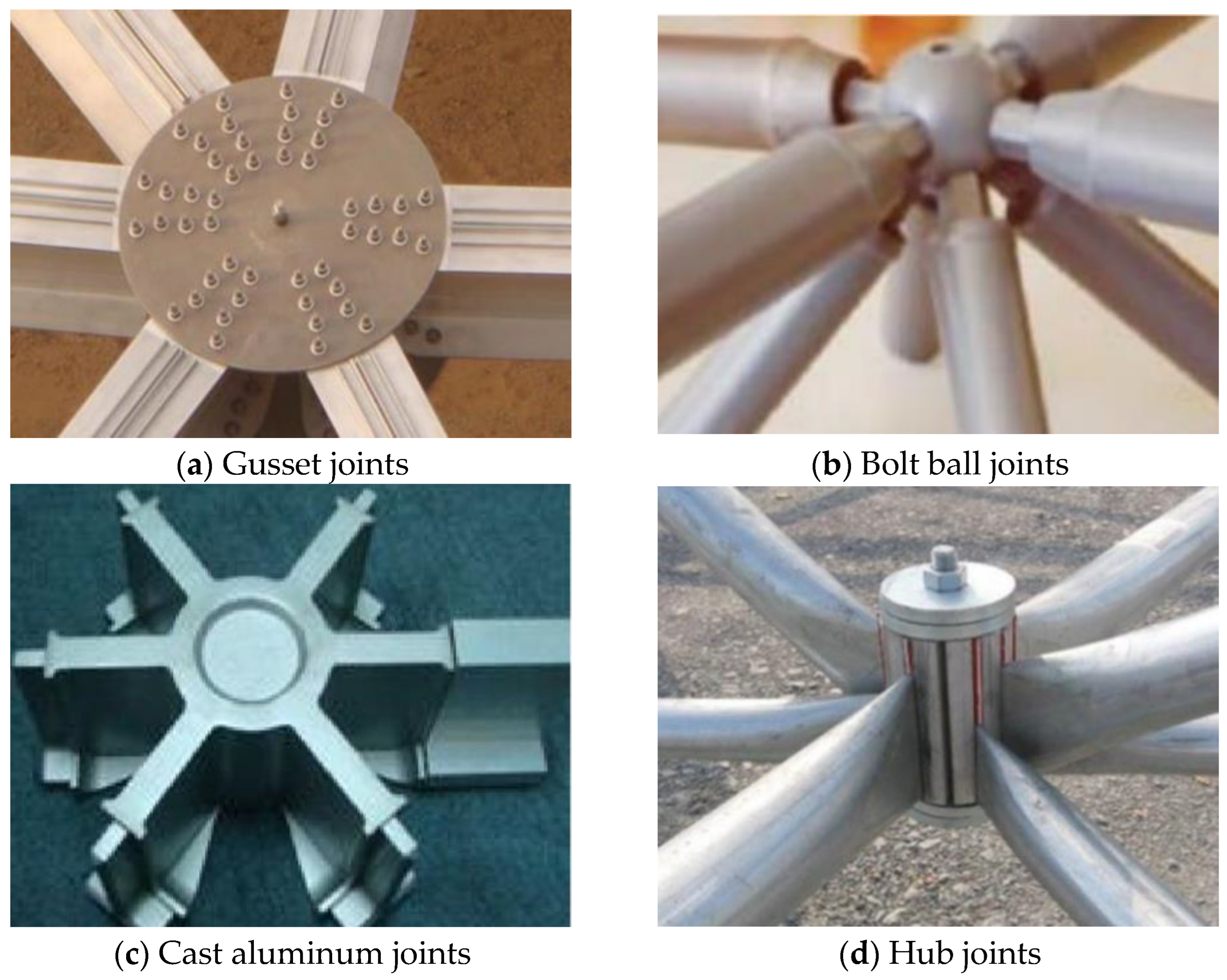
:1. Introduction
2. Test Scheme
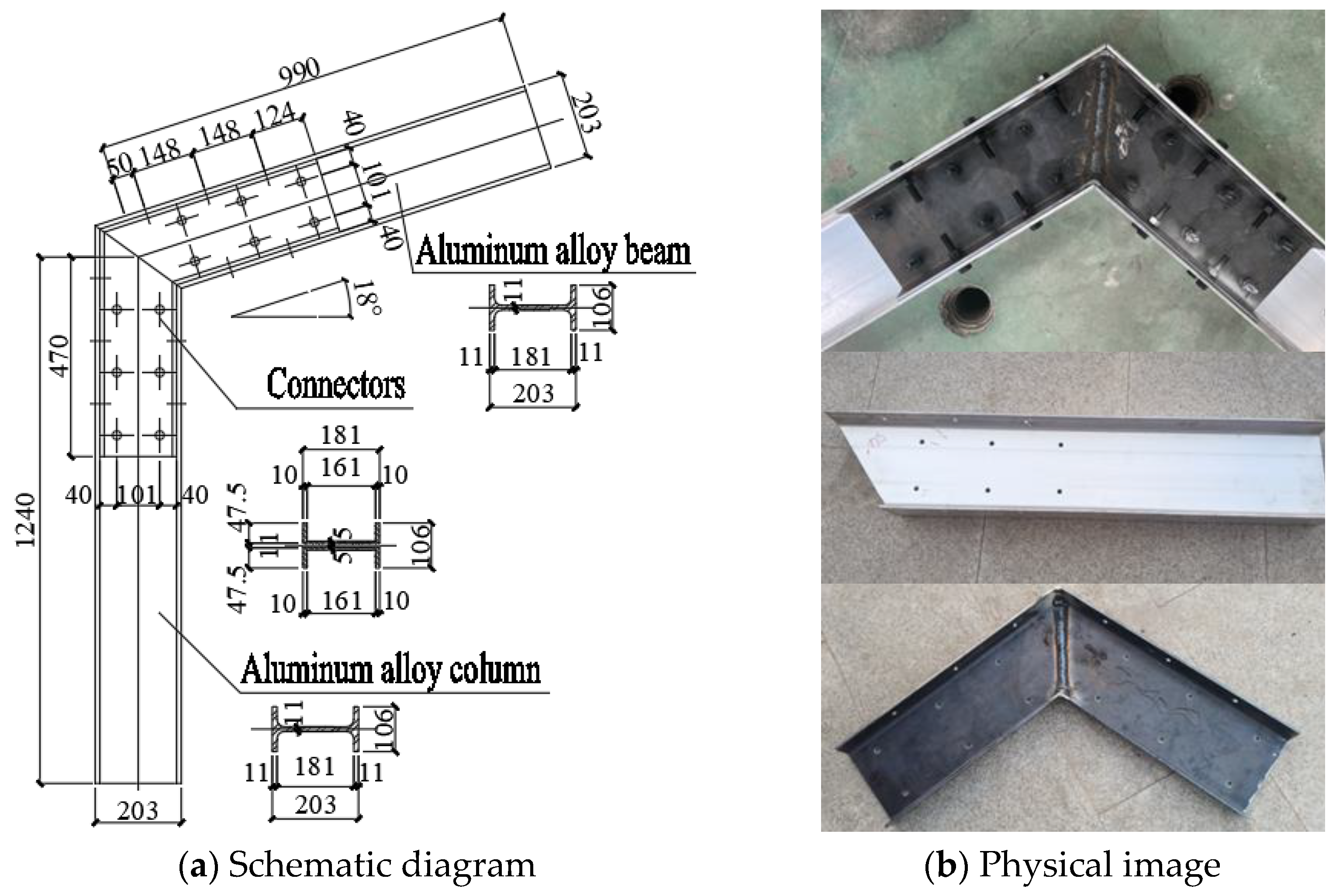
2.1. Specimens Design
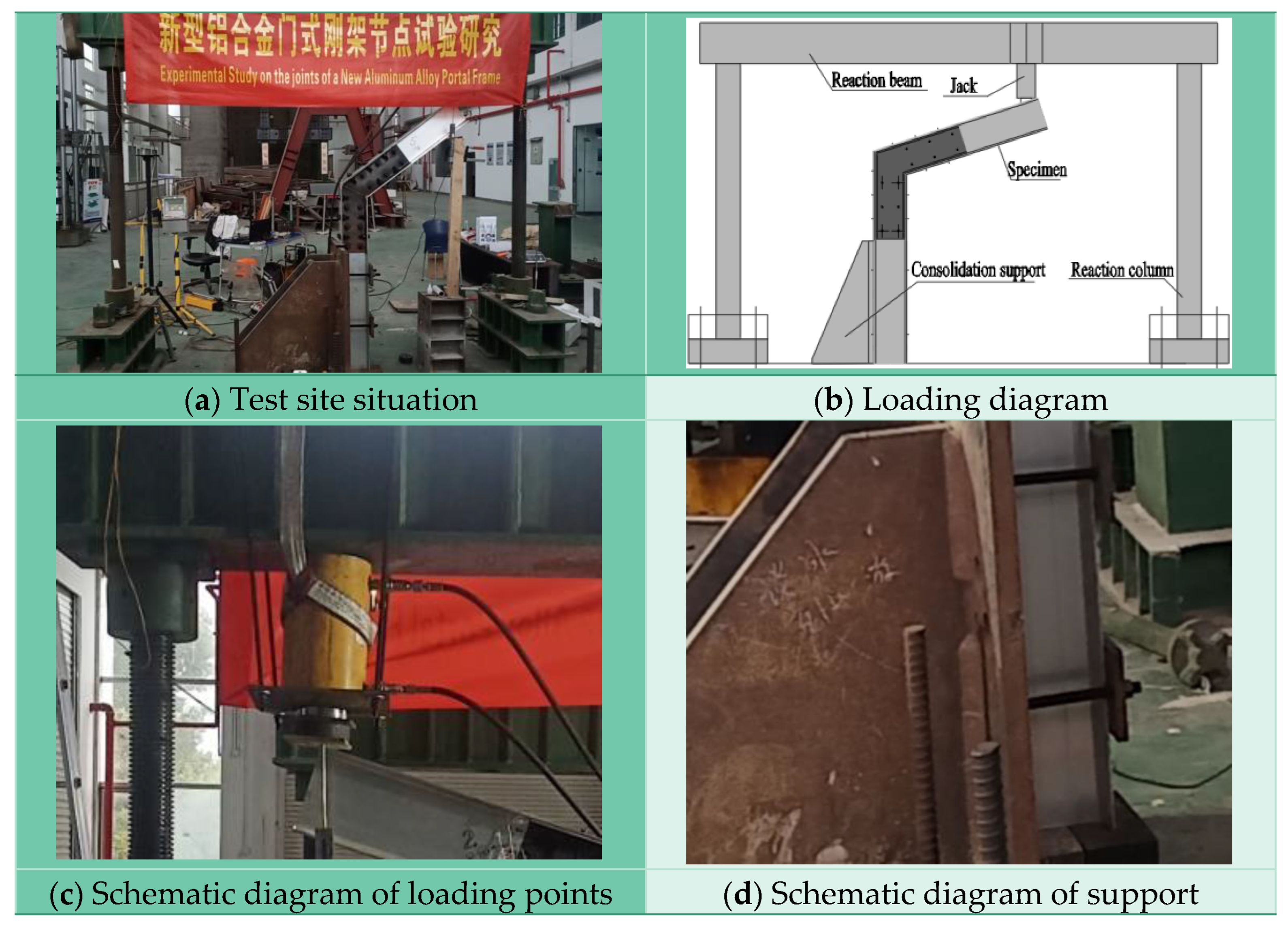
2.2. Testing System
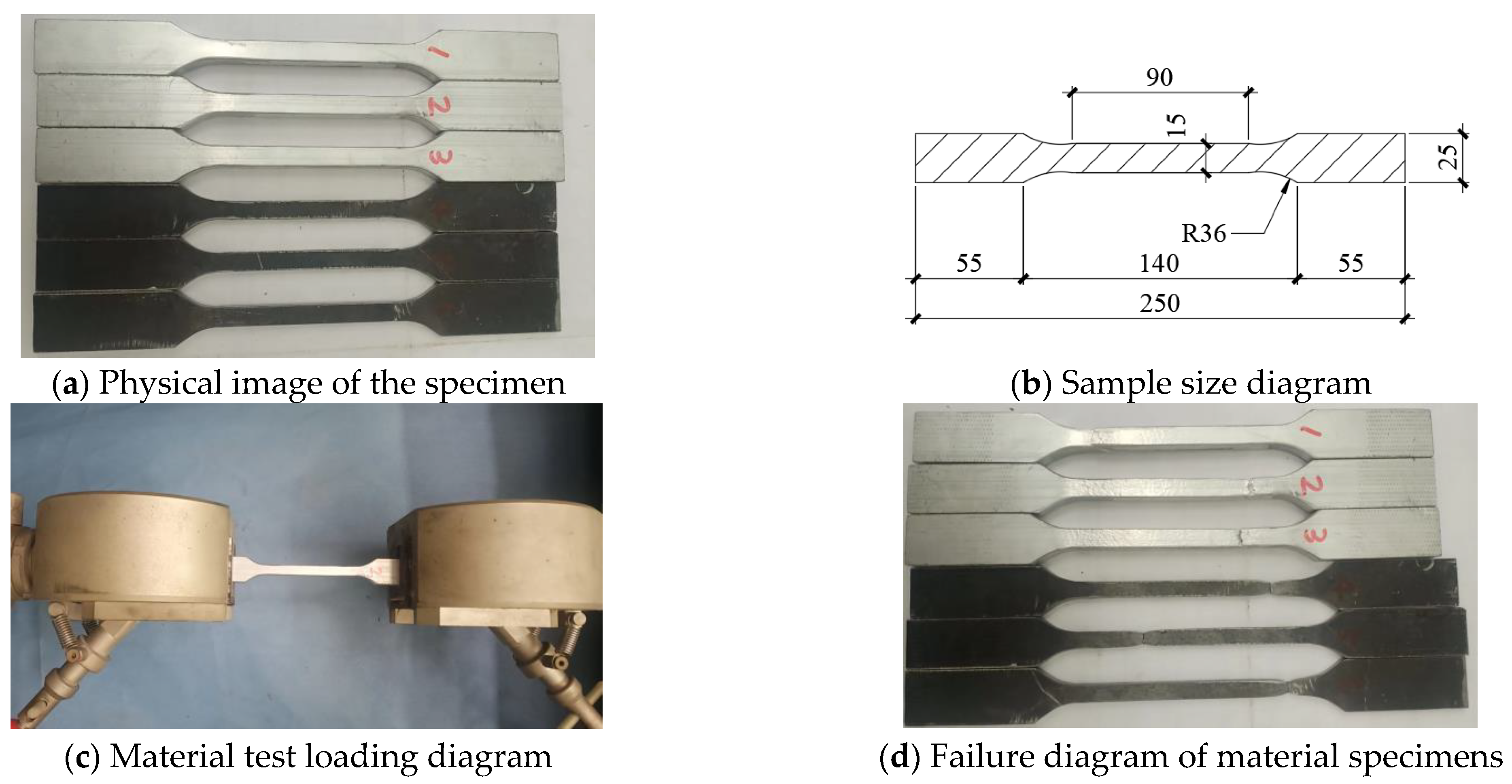
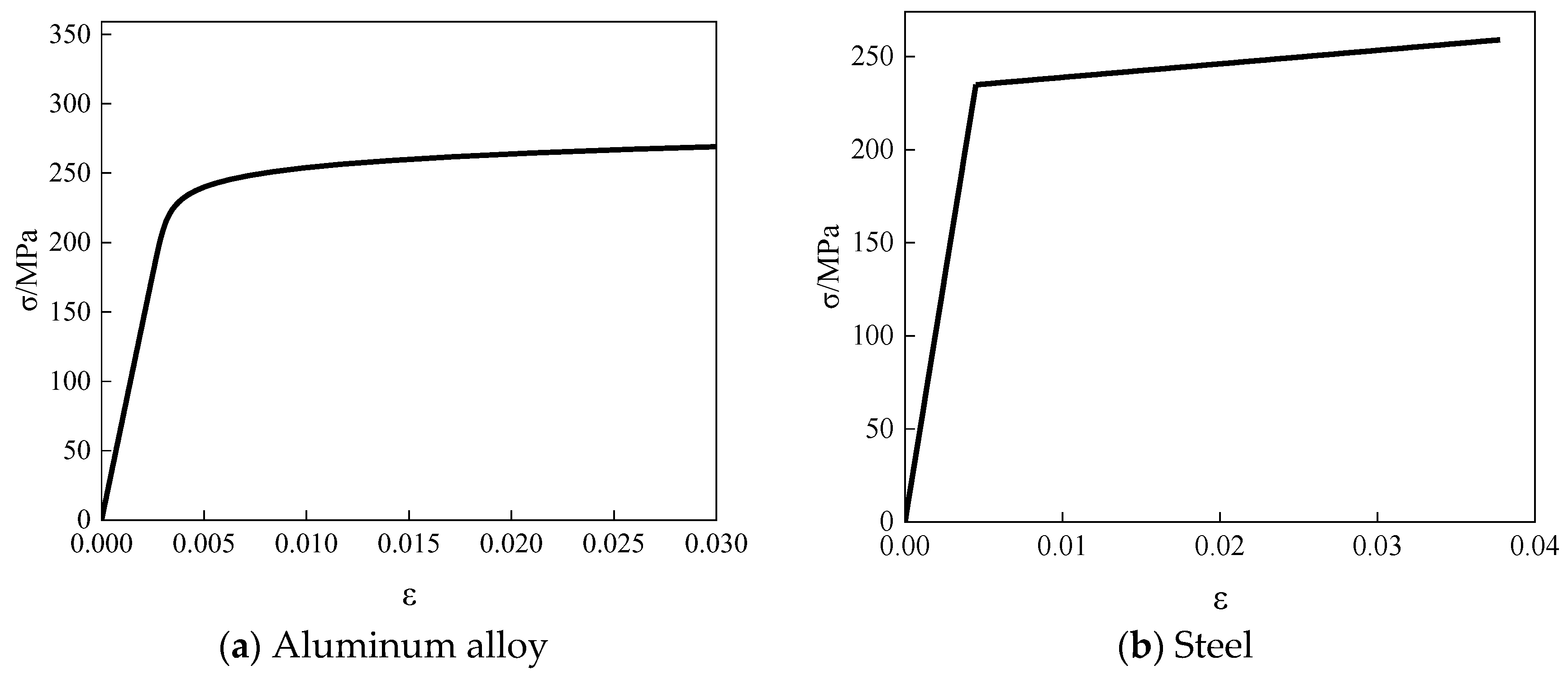
2.3. Material Property Test
3. Analysis of Test Results
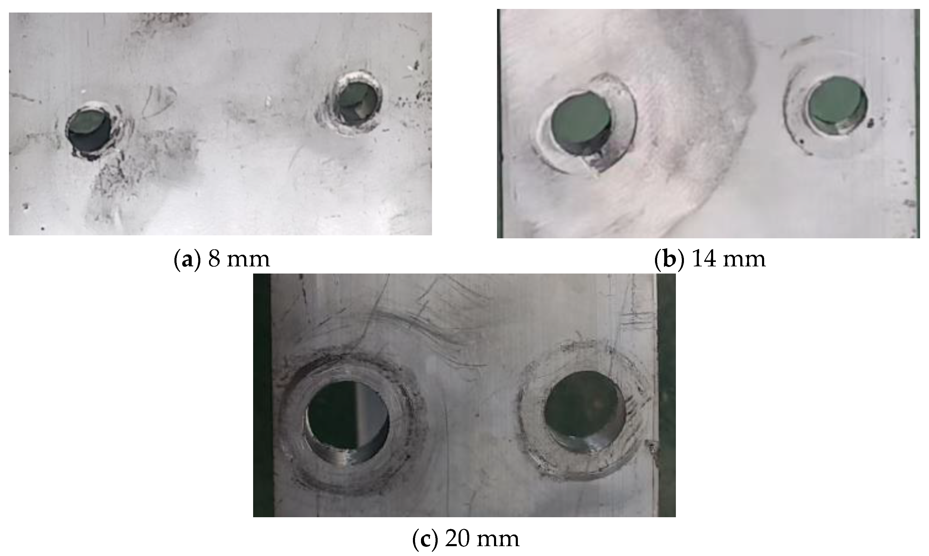
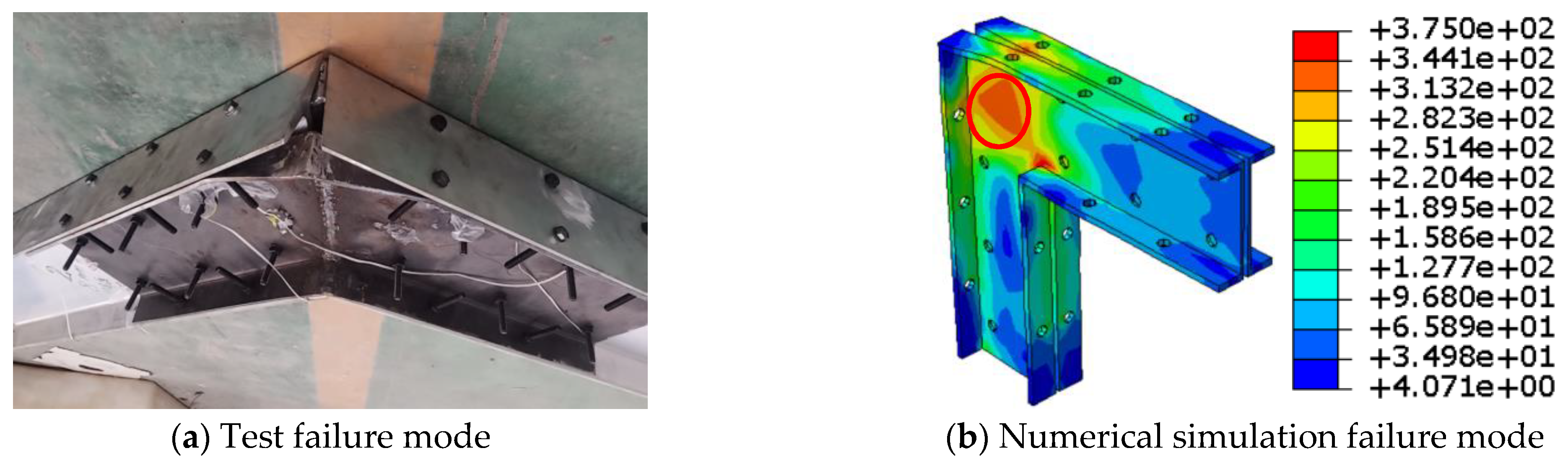
3.1. Failure Characteristics
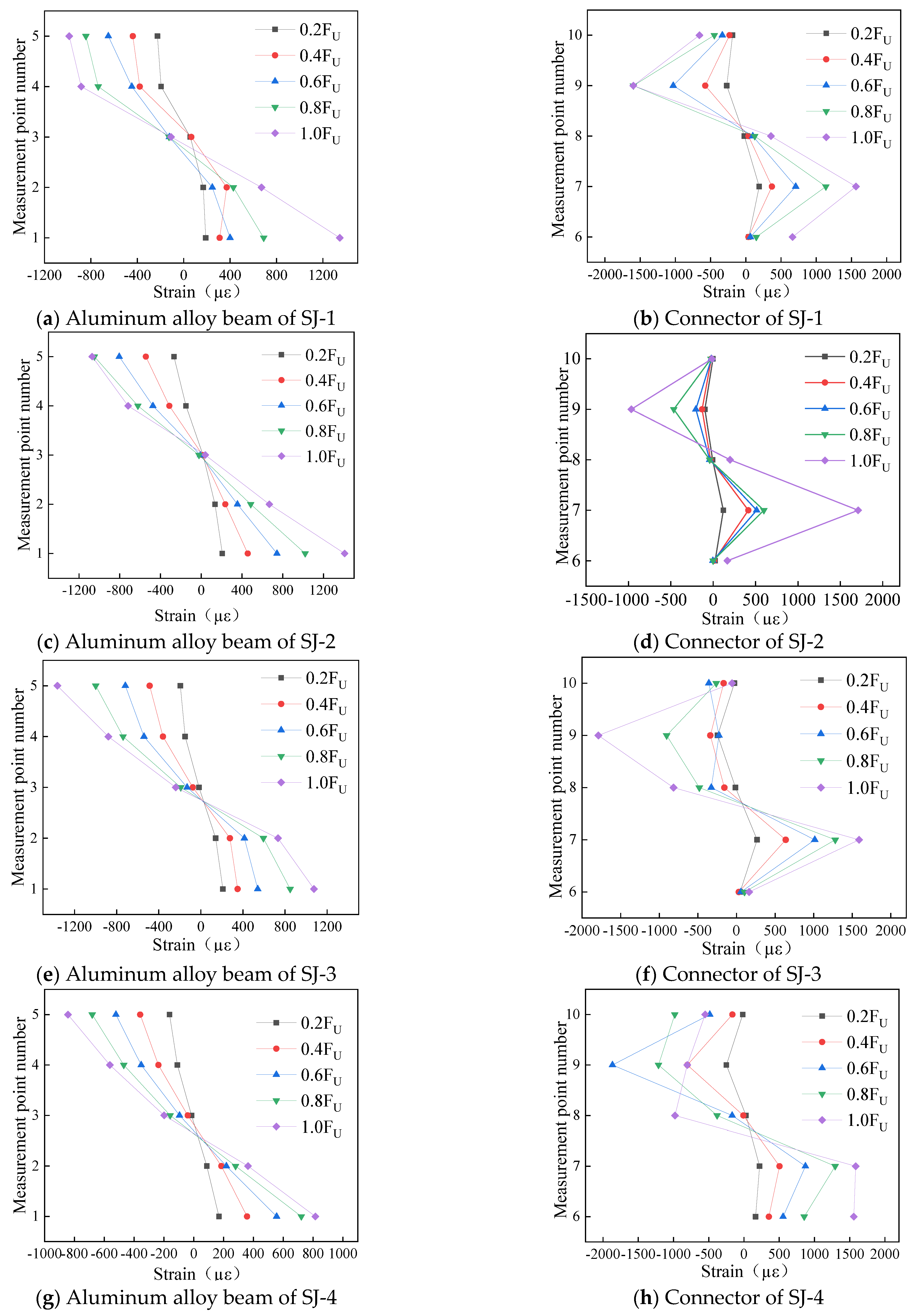
3.2. Strain Curve
- (1)
- The cross-sectional strain distribution of aluminum alloy beams and channel steel connectors of each specimen is basically consistent, which is due to the similar structural forms and consistent loading methods of each joint specimen;
- (2)
- The strain distribution of aluminum alloy beams is similar to that of composite I-shaped sections under bending moment, showing a general pattern of larger strain on the upper and lower flanges and smaller strain on the web;
- (3)
- The maximum strain of the channel steel connection occurs at the junction of the web and the upper and lower flanges, with the strain values of the upper and lower flanges in the middle and the strain in the middle of the web being the smallest.
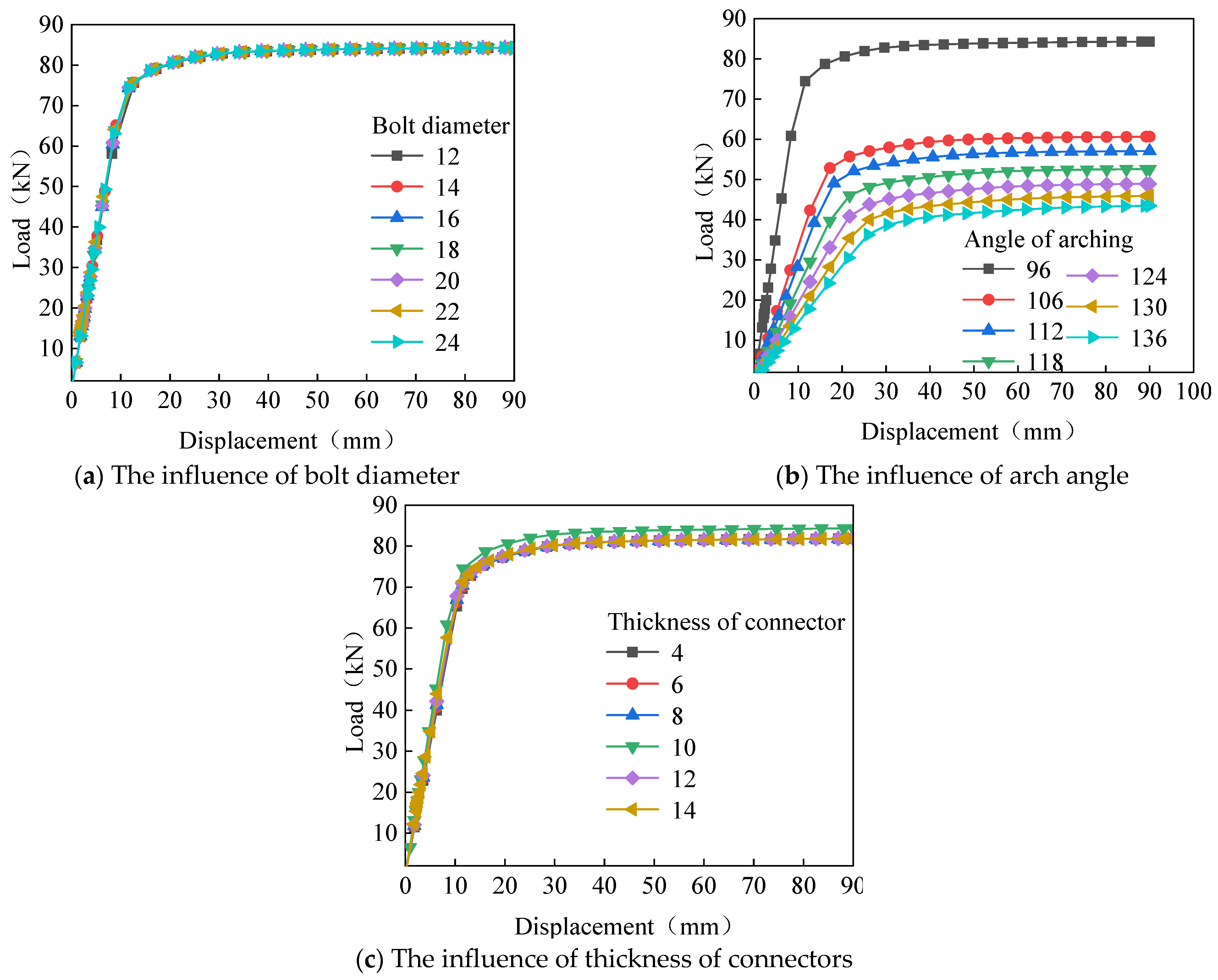
3.3. Load–Displacement Curve
4. Establishment of Numerical Models
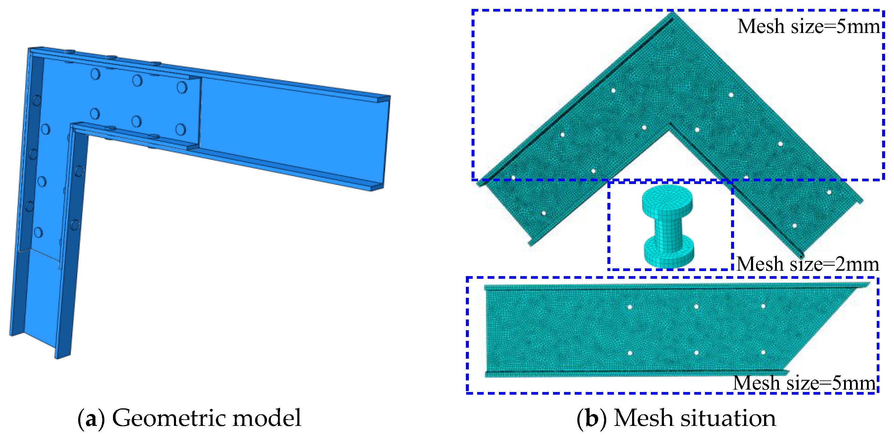
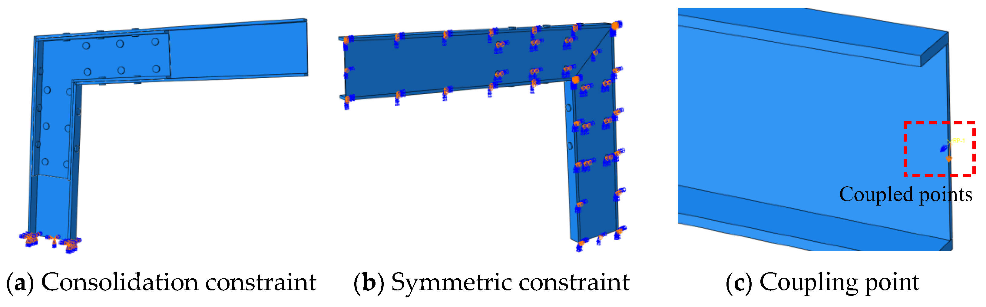
4.1. Numerical Model
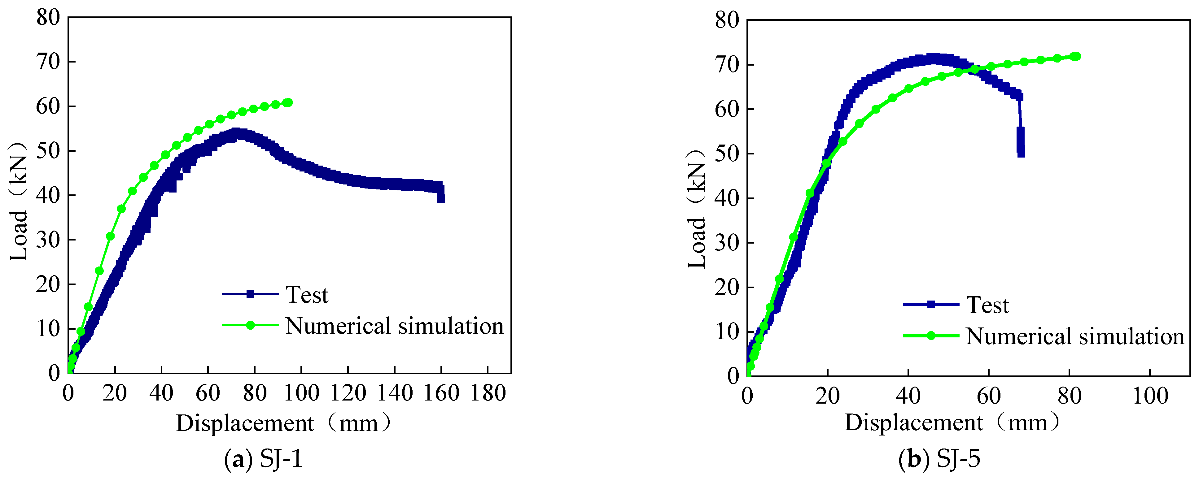
4.2. Model Validation
5. Parameterized Analysis of Numerical Simulation
5.1. Basic Model Parameters
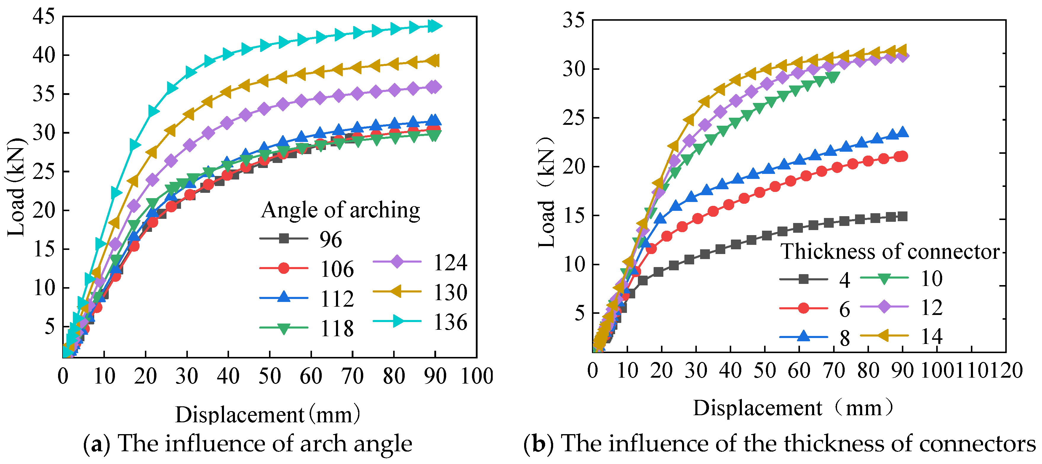
5.2. Mechanical Properties under Vertical Loads
- (1)
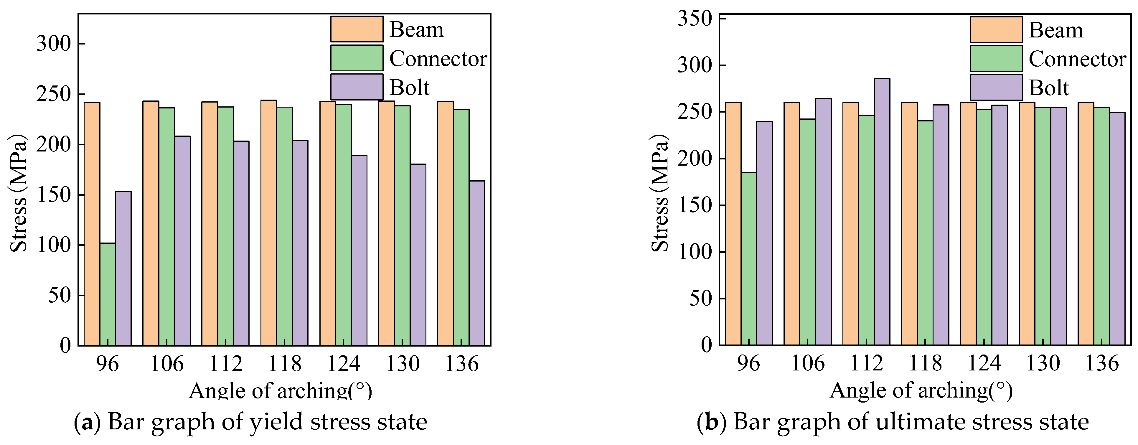
- As the arch angle increases (from 96 degrees to 136 degrees), there is no obvious change in yield displacement and ultimate displacement, and the change amplitude is small. The yield load and ultimate load gradually increase (2.04 times and 1.90 times, respectively), and the failure characteristics gradually change from groove type connection failure to H-type aluminum alloy rod failure;
- (2)
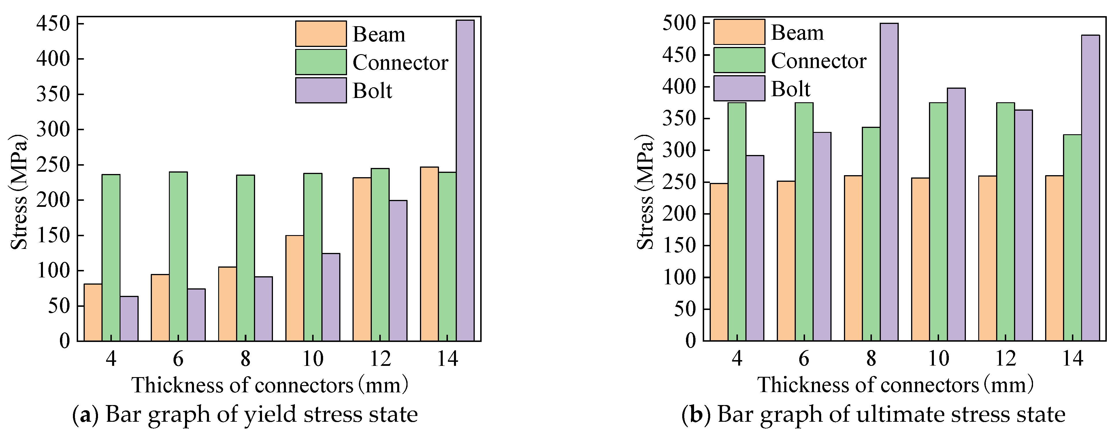
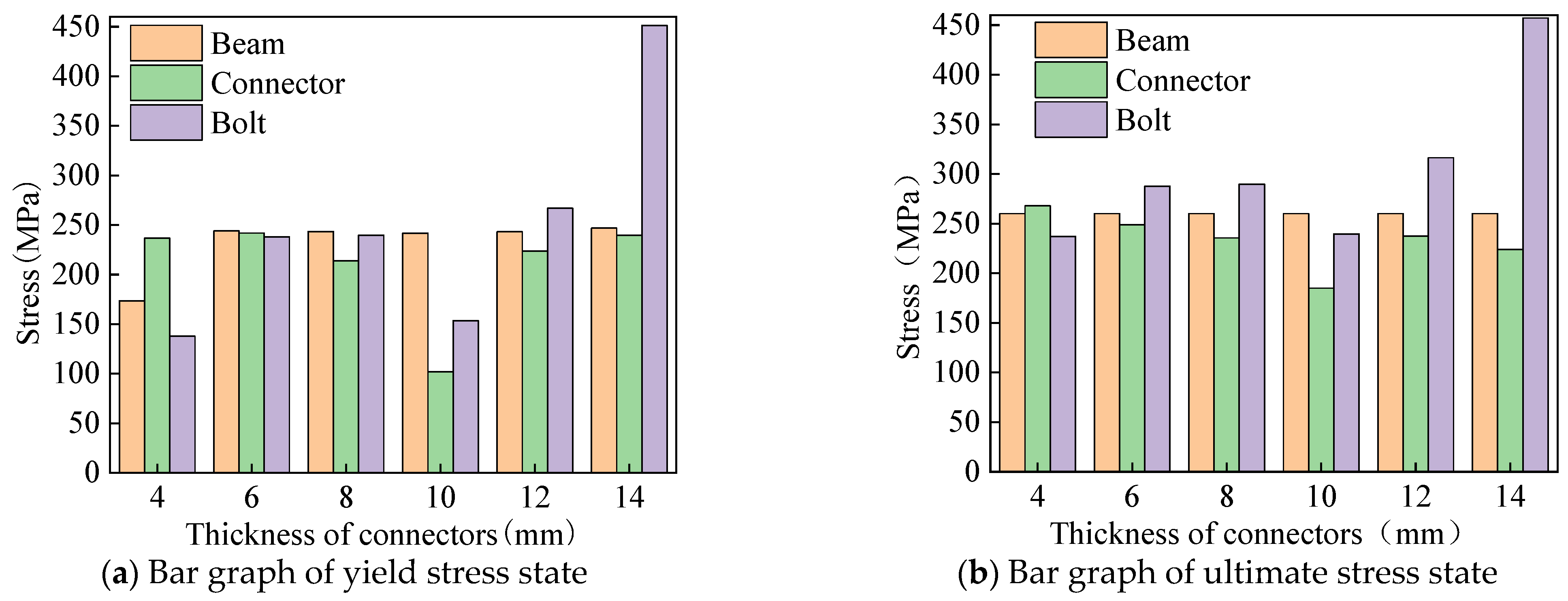
- As the wall thickness of the groove type connector increases from 4 mm to 14 mm, the yield displacement and yield load increase by 2.44 and 3.96 times, respectively, and the ultimate displacement and ultimate load increase by 1.8 and 2.46 times, respectively. The failure characteristic changes from the groove type connector failure to the H-type aluminum alloy rod failure;
- (3)
- As the arch angle increases, there is a gradual increase in vertical bearing capacity of beam-column joints. As the wall thickness of groove connectors increases, the increase in vertical bearing capacity of beam-column joints is gradually reduced.
5.3. Mechanical Properties under Horizontal Loads
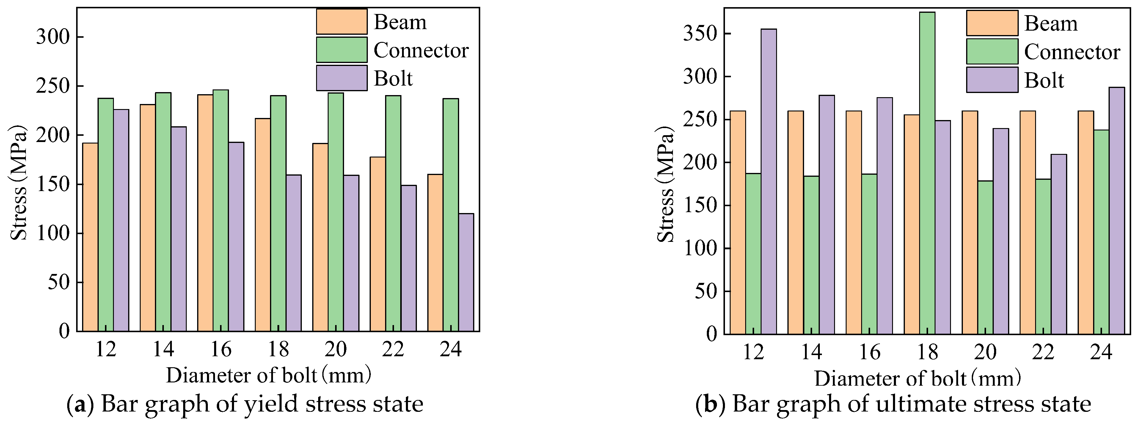
- (1)
- Under horizontal load, as the bolt diameter increases, there is no significant change in the yield load, yield displacement, ultimate load, and ultimate displacement of the beam-column joint, and the change amplitude is minimal. This is because when the bearing capacity of the bolt group is greater than the bearing capacity of the member section, increasing the bolt diameter does not enhance the horizontal bearing performance.
- (2)
- When the beam-column joint is subjected to horizontal load, as the arch angle increases, the yield and ultimate displacement gradually increase (2.14 times and 2.78 times, respectively), and the yield and ultimate load gradually decrease (58% and 48%, respectively). This is because as the arch angle increases, the axial force generated by the horizontal load gradually decreases and the bending moment gradually increases.
- (3)
- The wall thickness of different groove connectors has little effect on the horizontal load-bearing performance of aluminum alloy portal frame beam-column joints. For instance, as the wall thickness changes, the load–displacement curves basically overlap, and the changes in yield displacement, yield load, ultimate displacement, and ultimate load are minimal.
- (4)
- Under horizontal loads, the failure mode of joints mainly manifests as beam failure and connector failure under different bolt diameters, arch angles, and connection wall thicknesses.
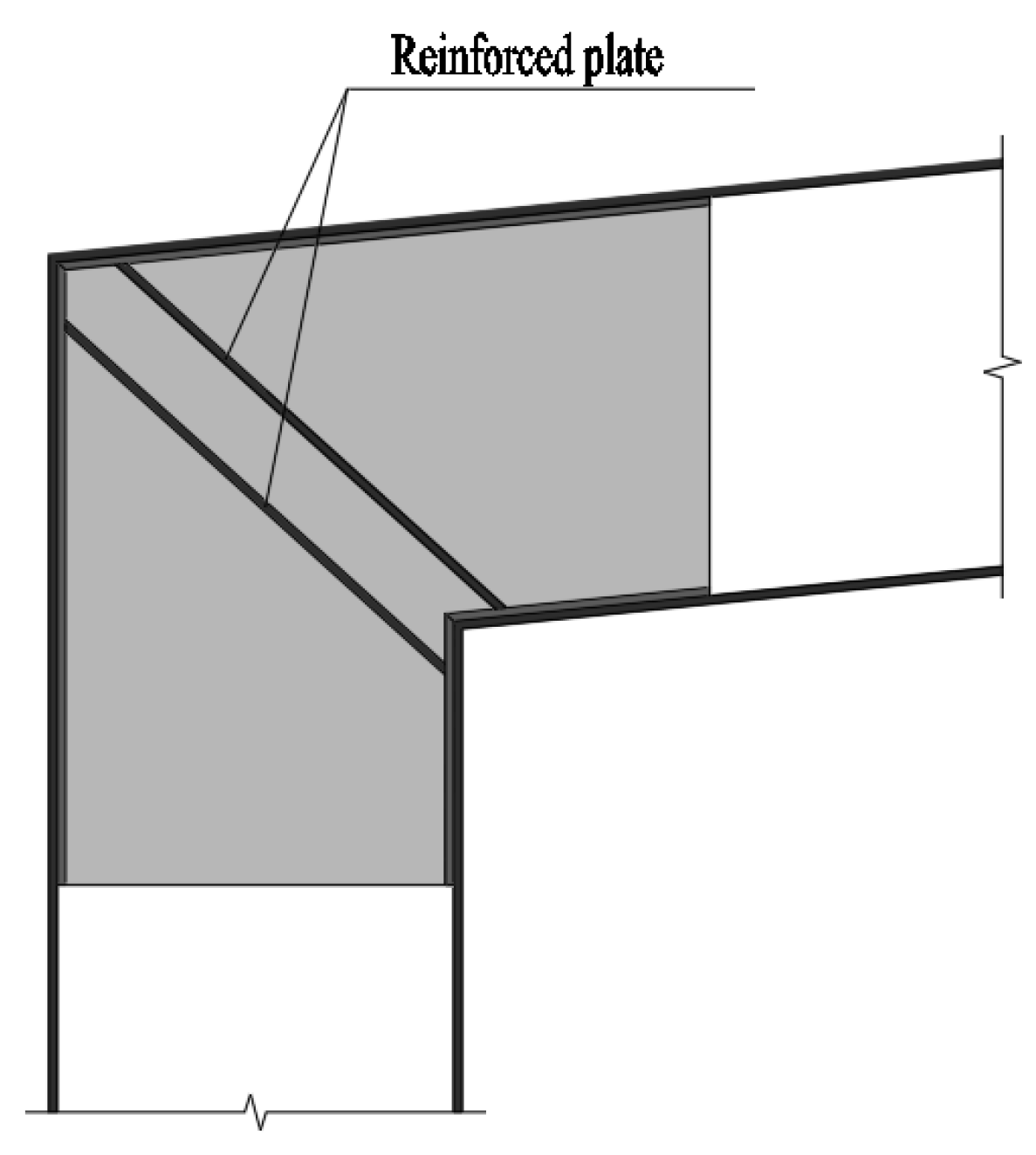
6. Joint Construction Design
6.1. Joint Construction Improvement
6.2. Joint Design Method
7. Conclusions
- (1)
- The experimental results indicate that as the diameter of the bolt increases, the damage situation at the bolt hole diameter of the specimen continues to improve, and the degree of compression at the bolt hole wall gradually decreases. The failure mode of beam-column joints does not change significantly with the change in arch angle, that is, the change in arch angle has no effect on the failure form and location of the specimen.
- (2)
- The experimental results show that the load–displacement curve mainly consists of three stages, namely, the elastic stage, yield stage, and degradation stage. In the elastic stage, the load–displacement curves of different bolt diameters are basically consistent. After entering the plastic stage, the ultimate load first increases and then decreases, and the ultimate displacement is basically consistent.
- (3)
- According to the experiment, there is no significant difference in the load–displacement curve when the arch angle increases from 90 degrees to 108 degrees. When the arch angle increases to 126 degrees, the stiffness and ultimate bearing capacity of the joint under vertical load significantly increase.
- (4)
- As the wall thickness of the groove type connector increases from 4 mm to 14 mm, the vertical yield displacement and yield load increase by 2.44 and 3.96 times, respectively, and the ultimate displacement and ultimate load increase by 1.8 and 2.46 times, respectively.
- (5)
- Under horizontal load, as the diameter of the bolt increases, the yield load, yield displacement, ultimate load, and ultimate displacement of the beam-column joint show no significant changes, and the amplitude of changes is minimal.
- (6)
- When the beam-column joint is subjected to horizontal loads, as the arch angle increases, the yield and ultimate displacement increase by 2.14 times and 2.78 times, respectively, and the yield and ultimate load decrease by 58% and 48%, respectively.
- (7)
- The research results of this article can be used for the design of aluminum alloy portal frames, and a series of studies on the mechanical performance of the overall portal frame structure should be carried out in the future.
Author Contributions
Funding
Data Availability Statement
Acknowledgments
Conflicts of Interest
References
- Guo, X.; Xiong, Z.; Luo, Y.; Xu, H.; Liang, S. Block tearing and local buckling of aluminum alloy gusset joint plates. KSCE J. Civ. Eng. 2016, 20, 820–831. [Google Scholar] [CrossRef]
- Guo, X.; Xiong, Z.; Luo, Y.; Qiu, L.; Liu, J. Experimental investigation on the semi-rigid behaviour of aluminium alloy gusset joints. Thin-Walled Struct. 2015, 87, 30–40. [Google Scholar] [CrossRef]
- Xiong, Z.; Guo, X.; Luo, Y.; Xu, H. Numerical analysis of aluminium alloy gusset joints subjected to bending moment and axial force. Eng. Struct. 2017, 152, 1–13. [Google Scholar] [CrossRef]
- Guo, X.; Zhu, S.; Liu, X.; Liu, L. Experimental study on hysteretic behavior of aluminum alloy gusset joints. Thin-Walled Struct. 2018, 131, 883–901. [Google Scholar] [CrossRef]
- Ma, H.; Yu, L.; Fan, F.; Yu, Z. Mechanical performance of an improved semi-rigid joint system under bending and axial forces for aluminum single-layer reticulated shells. Thin-Walled Struct. 2019, 142, 322–339. [Google Scholar] [CrossRef]
- Xu, S.; Chen, Z.; Wang, X.; Mazzolani, F.M. Hysteretic out-of-plane behavior of the temcor joint. Thin-Walled Struct. 2015, 94, 585–592. [Google Scholar] [CrossRef]
- Wu, Y.; Liu, H.; Chen, Z.; Liu, Y. Study on low-cycle fatigue performance of aluminum alloy temcor joints. KSCE J. Civ. Eng. 2020, 24, 195–207. [Google Scholar] [CrossRef]
- Wang, G.; Zhao, C.Q.; Ma, J. Experimental and numerical study on the bending performance of an aluminium alloy flower-gusset composite joint. Structures 2021, 33, 2475–2486. [Google Scholar]
- Wang, G.; Zhao, C.Q. Experimental and theoretical study on the bearing capacity of FGC joints for single-layer aluminium alloy lattice shell structures. Structures 2021, 33, 2445–2458. [Google Scholar]
- Hiyama, Y.; Ishikawa, K.; Kato, S. Buckling behaviour of aluminum alloy double layer truss grid using ball joint system. In Proceedings of the IASS-LAS98 Conference; International Association for Shell and Spatial Structure (IASS): Madrid, Spain, 1998; Volume 9. [Google Scholar]
- Liu, H.; Gu, A.; Chen, Z. Mechanical properties and design method of aluminum alloy bolt-sphere Joints. Struct. Eng. Int. 2019, 31, 30–39. [Google Scholar] [CrossRef]
- Liu, H.; Gu, A.; Chen, Z. Tensile properties of aluminum alloy bolt-sphere joints under elevated temperatures. KSCE J. Civ. Eng. 2020, 24, 525–536. [Google Scholar] [CrossRef]
- Shi, G.; Ban, H.; Bai, Y.; Wang, Y.; Luo, C.; Shi, Y. A novel cast aluminum joint for reticulated shell structures: Experimental study and modeling. Adv. Struct. Eng. 2013, 16, 1047–1059. [Google Scholar] [CrossRef]
- Sugizaki, K.; Kohmura, S. Experimental study on buckling behaviour of a triodetic aluminum space frame. In Proceedings of the International Association for Shell and Space Structure, Tokyo, Japan, 19–22 October 1993; Volume 10, pp. 205–212. [Google Scholar]
- Sugizaki, K.; Kohmura, S. Experimental study on buckling behaviour of a triodetic aluminum space frame: No.2 ultimate bearing strength of a single-layer space frame. In Proceedings of the IASS-ASCE International Symposium, Atlanta, GA, USA, 24–28 April 1994; Volume 4, pp. 478–484. [Google Scholar]
- Yonemaru, K.; Fujisaki, T.; Nakatsuji, T. Development of space truss structure with CFRP. Mater. Struct. 1997, 8, 81–87. [Google Scholar]
- Mazzolani, F.M. 3D aluminium structures. Thin-Walled Struct. 2012, 61, 258–266. [Google Scholar] [CrossRef]
- Wang, Y.; Fan, F.; Lin, S. Experimental investigation on the stability of aluminium alloy 6082 circular tubes in axial compression. Thin-Walled Struct. 2015, 89, 54–66. [Google Scholar] [CrossRef]
- GB/T 50429-2007; Code for Design of Aluminium Structures. General Administration of Quality Supervision, Inspection and Quarantine of the People’s Republic of China: Beijing, China, 2007.
- GB/T 228.1-2010; Metallic Materials—Tensile Testing—Part 1: Method of Test at Room Temperature. General Administration of Quality Supervision, Inspection and Quarantine of the People’s Republic of China: Beijing, China, 2011.
- Sun, Y.; Zhang, K.; Gong, G. Material properties of structural aluminium alloys after exposure to fire. Structures 2023, 55, 2105–2111. [Google Scholar] [CrossRef]
- Ramberg, W.; Osgood, W.R. Description of Stress-Strain Curves by Three Parameters; NACA TN-902; National Advisory Committee for Aeronautics: Washington, DC, USA, 1943. [Google Scholar]
- Sun, Y.; Fu, Z.; Song, Y.; Xia, J. Cross-Sectional Behavior of Aluminum Alloy Channel Section Stub Columns after Exposure to Fire. J. Struct. Eng. 2023, 149, 04023085. [Google Scholar] [CrossRef]
- Zhou, W.; Ai, S.; Chen, M.; Zhang, R.; He, R.; Pei, Y.; Fang, D. Preparation and thermodynamic analysis of the porous ZrO2/(ZrO2 + Ni) functionally graded bolted joint. Compos. Part B Eng. 2015, 82, 13–22. [Google Scholar] [CrossRef]
- Zhou, W.; Zhang, R.; Fang, D. Design and analysis of the porous ZrO2/(ZrO2+Ni) ceramic joint with load bearing-heat insulation integration. Ceram. Int. 2015, 42, 1416–1424. [Google Scholar] [CrossRef]
- Tian, L.; Li, M.; Li, L.; Li, D.; Bai, C. Novel joint for improving the collapse resistance of steel frame structures in column-loss scenarios. Thin-Walled Struct. 2023, 182, 110219. [Google Scholar] [CrossRef]
- Yang, Y.; Lin, B.; Zhang, W. Experimental and numerical investigation of an arch–beam joint for an arch bridge. Arch. Civ. Mech. Eng. 2023, 23, 101. [Google Scholar] [CrossRef]


| Specimen | Bolt Diameter (mm) | Arch Angle (°) | Beam Section Size (mm) | Connection Section Size (mm) |
|---|---|---|---|---|
| SJ-1 | 8 | 108 | H203 × 106 × 11 × 11 | 2C181 × 47.5 × 5 × 10 |
| SJ-2 | 14 | 108 | H203 × 106 × 11 × 11 | 2C181 × 47.5 × 5 × 10 |
| SJ-3 | 20 | 108 | H203 × 106 × 11 × 11 | 2C181 × 47.5 × 5 × 10 |
| SJ-4 | 20 | 90 | H203 × 106 × 11 × 11 | 2C181 × 47.5 × 5 × 10 |
| SJ-5 | 20 | 126 | H203 × 106 × 11 × 11 | 2C181 × 47.5 × 5 × 10 |
| Material | Yield Strength MPa | Tensile Strength MPa | Elastic Modulus GPa |
|---|---|---|---|
| 6061-T6 | 239 | 264 | 70.5 |
| Q235 | 235 | 360 | 206 |
| Bolt | 887 | 992 | 204 |
| Specimen | Type | Displacement (mm) | Load (kN) |
|---|---|---|---|
| SJ-1 | Test | 72.8 | 53.40 |
| FEA | 72.8 | 58.17 | |
| SJ-5 | Test | 48.6 | 71.60 |
| FEA | 48.6 | 67.59 | |
| Error | 4.77% | 4.01% |
| Arch Angle (°) | Yield Displacement (mm) | Yield Load (kN) | Failure Characteristics | Failure Displacement (mm) | Failure Load (kN) |
|---|---|---|---|---|---|
| 96 | 8.38 | 5.94 | Connector | 48.38 | 26.10 |
| 106 | 8.21 | 7.47 | Connector | 45.71 | 24.53 |
| 112 | 8.81 | 8.67 | Connector | 44.15 | 27.07 |
| 118 | 8.21 | 8.94 | Beam | 48.85 | 29.25 |
| 124 | 7.25 | 9.75 | Beam | 48.65 | 33.10 |
| 130 | 8.21 | 11.98 | Beam | 44.21 | 36.10 |
| 136 | 7.25 | 12.13 | Beam | 46.65 | 40.14 |
| Thickness (mm) | Yield Displacement (mm) | Yield Load (kN) | Failure Characteristics | Failure Displacement (mm) | Failure Load (kN) |
|---|---|---|---|---|---|
| 4 | 4.60 | 3.02 | Connector | 30.50 | 14.67 |
| 6 | 5.28 | 4.00 | Connector | 39.71 | 24.53 |
| 8 | 6.31 | 5.21 | Connector | 46.59 | 19.16 |
| 10 | 8.38 | 5.94 | Beam | 48.38 | 26.10 |
| 12 | 10.94 | 10.18 | Beam | 50.58 | 28.48 |
| 14 | 11.21 | 11.98 | Beam | 54.21 | 36.10 |
| Arch Angle (°) | Yield Displacement (mm) | Yield Load (kN) | Failure Characteristics | Failure Displacement (mm) | Failure Load (kN) |
|---|---|---|---|---|---|
| 96 | 6.15 | 18.22 | Beam | 19.21 | 39.56 |
| 106 | 6.22 | 18.91 | Beam | 19.03 | 39.58 |
| 112 | 6.76 | 19.30 | Beam | 20.61 | 40.32 |
| 118 | 6.25 | 22.76 | Beam | 19.15 | 39.62 |
| 124 | 5.76 | 21.40 | Beam | 20.61 | 40.33 |
| 130 | 6.51 | 23.77 | Beam | 19.78 | 39.55 |
| 136 | 6.74 | 24.65 | Beam | 20.37 | 40.29 |
| Arch Angle (°) | Yield Displacement (mm) | Yield Load (kN) | Failure Characteristics | Failure Displacement (mm) | Failure Load (kN) |
|---|---|---|---|---|---|
| 96 | 5.79 | 21.40 | Beam | 20.61 | 40.33 |
| 106 | 8.21 | 13.73 | Beam | 30.71 | 28.99 |
| 112 | 9.82 | 14.14 | Beam | 36.17 | 27.51 |
| 118 | 12.71 | 14.76 | Beam | 39.71 | 25.29 |
| 124 | 12.71 | 12.27 | Beam | 44.21 | 23.55 |
| 130 | 12.71 | 10.47 | Beam | 48.71 | 22.13 |
| 136 | 12.38 | 8.89 | Beam | 57.38 | 21.13 |
| Thickness (mm) | Yield Displacement (mm) | Yield Load (kN) | Failure Characteristics | Failure Displacement (mm) | Failure Load (kN) |
|---|---|---|---|---|---|
| 4 | 6.21 | 21.43 | Connector | 19.49 | 38.62 |
| 6 | 6.31 | 20.40 | Connector | 19.49 | 38.67 |
| 8 | 6.35 | 20.66 | Connector | 19.49 | 38.70 |
| 10 | 5.79 | 21.40 | Beam | 20.61 | 40.33 |
| 12 | 6.39 | 21.118 | Beam | 19.49 | 38.74 |
| 14 | 6.86 | 22.16 | Beam | 20.78 | 39.00 |
Disclaimer/Publisher’s Note: The statements, opinions and data contained in all publications are solely those of the individual author(s) and contributor(s) and not of MDPI and/or the editor(s). MDPI and/or the editor(s) disclaim responsibility for any injury to people or property resulting from any ideas, methods, instructions or products referred to in the content. |
© 2023 by the authors. Licensee MDPI, Basel, Switzerland. This article is an open access article distributed under the terms and conditions of the Creative Commons Attribution (CC BY) license (https://creativecommons.org/licenses/by/4.0/).
Share and Cite
Xing, Z.; Wang, G.; Lin, X.; Pang, J.; Zhao, C.; Chen, Q. Study of the Mechanical Properties of Beam-Column Joints in a New Type of Aluminum Alloy Portal Frame. Buildings 2023, 13, 2698. https://doi.org/10.3390/buildings13112698
Xing Z, Wang G, Lin X, Pang J, Zhao C, Chen Q. Study of the Mechanical Properties of Beam-Column Joints in a New Type of Aluminum Alloy Portal Frame. Buildings. 2023; 13(11):2698. https://doi.org/10.3390/buildings13112698
Chicago/Turabian StyleXing, Zhanqing, Gang Wang, Xiaolin Lin, Jing Pang, Caiqi Zhao, and Qiaosheng Chen. 2023. "Study of the Mechanical Properties of Beam-Column Joints in a New Type of Aluminum Alloy Portal Frame" Buildings 13, no. 11: 2698. https://doi.org/10.3390/buildings13112698
APA StyleXing, Z., Wang, G., Lin, X., Pang, J., Zhao, C., & Chen, Q. (2023). Study of the Mechanical Properties of Beam-Column Joints in a New Type of Aluminum Alloy Portal Frame. Buildings, 13(11), 2698. https://doi.org/10.3390/buildings13112698