Abstract
An assembled floor system is a main step in the industrialization of construction in civil engineering, where the stiffness and anti-crack properties under designed loads and its self-weight are the main concerns. This paper presents a new type of assembled integral composite floor system, which is composed of precast ribbed bottom slab, lightweight infills, cast-in-situ upper slab and joints. Through the couplers for squeezing and splicing of longitudinal bars, shear keys and cast-in-situ joints between the precast panels and cast-in-situ upper part, the whole hollow floor system could not only exhibit satisfactory mechanical performance, but also lower the self-weight and shorten the construction time. To study its flexural behaviors, a full-scale specimen sized 9.2 m × 9.2 m was designed and tested under static area load. With the load increased to the designed loads of Chinese design code GB50010-2010, mechanical performance (i.e., crack distribution, deformation and stress distribution) were analyzed. To further study its load-carrying capacity and working mechanism, an effective finite element model was established in ABAQUS and compared with experimental and simulation results. It was found that the deflection of the floor under the normal service load and the crack width met the needs of normal use, and the finite element model could serve as a reliable method for the load-carrying capacity calculation.
1. Introduction
As a main part of building structures, the floor system withstands live loads and its self-weight and transfers them to vertical load-bearing components [1]. According to the structural forms, they could be categorized into two main types: beam-slab floor and beamless floor [2].
Theoretically, the slab and the beam are calculated separately by simplifying them into beam and one-way or two-way plate elements, respectively [3]. Thus, with the increase of span, the heights or depths of the beam and slab must be enlarged to bear the increasing self-weight of the floor system [4]. This would result in two economic concerns in real estate, which are material consumption and labor costs [5].
To balance the economic costs and mechanical needs, four main methods have been proposed in recent decades. Hollow slab was the first method conceived by engineers and researchers [6,7,8]. It was recognized that the parts with small stress of the slab should be eliminated to reduce its self-weight and construction costs without impairing its mechanical behavior. Furthermore, the cavity could be infilled with some insulation materials to improve its thermal and sound insulation properties. Experimental and theoretical research of this type, such as plastic bubble ball, foamed concrete infills, have been carried out and satisfactory results have been reached [9,10,11,12].
Two-way multi-ribbed floor systems turned out to be another effective solution [13]. By substituting beams with ribbed beams of lower height and smaller spacing, the story height could be reduced and the average costs of the building could be lowered.
To further reduce the total costs and protect the environment at the same time, assembled integral and assembled floor systems were proposed. With all or main components manufactured in factory, the construction period could be prominently shortened and the demands of casting template and labor could be greatly reduced. Ma proposed a Vierendeel-sandwich-plate floor system [14], which is composed of two layers of ribbed reinforced concrete slab connected by reinforced concrete shear keys at the intersection. Through the design and construction of a real-life project, the feasibility of this new floor system was verified. Other kinds of assembled or assembled integral in floor systems, such as PK prestressed composite slab floor system [15], the assembled monolithic hollow-ribbed floor [16], prefabricated PC floor system [17], and other new systems [18,19,20,21,22] were all investigated through experimental and theoretical methods. Though the assembled techniques could greatly shorten the construction time and enhance the construction efficiency, there is still an urging worry about its stiffness and anti-crack properties under designed load.
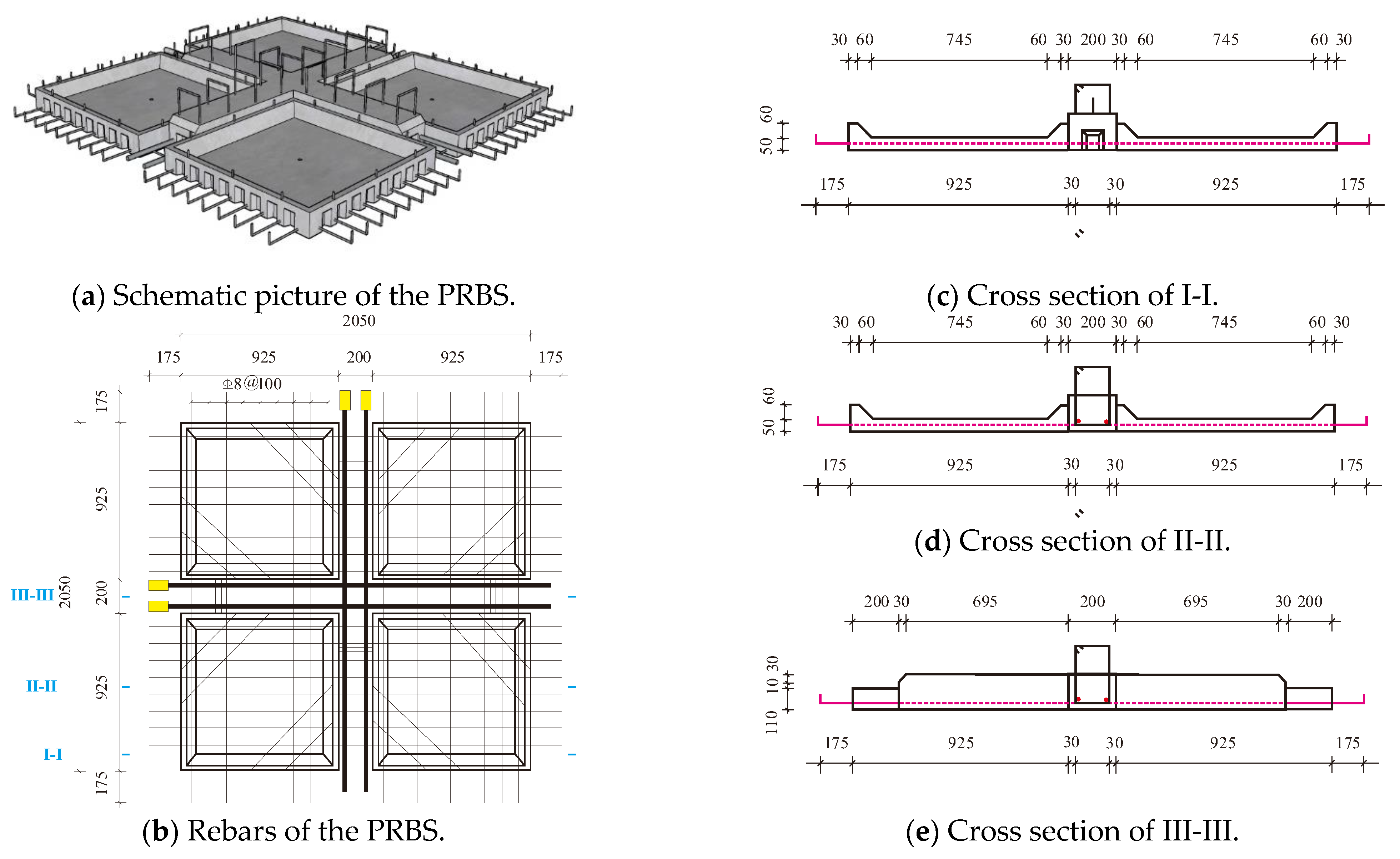
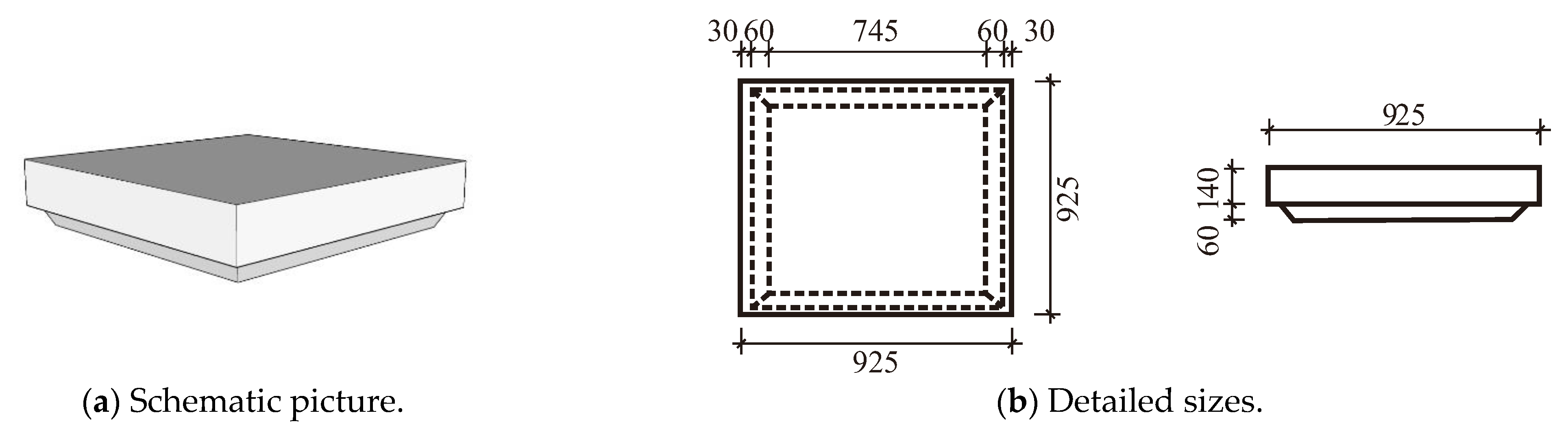
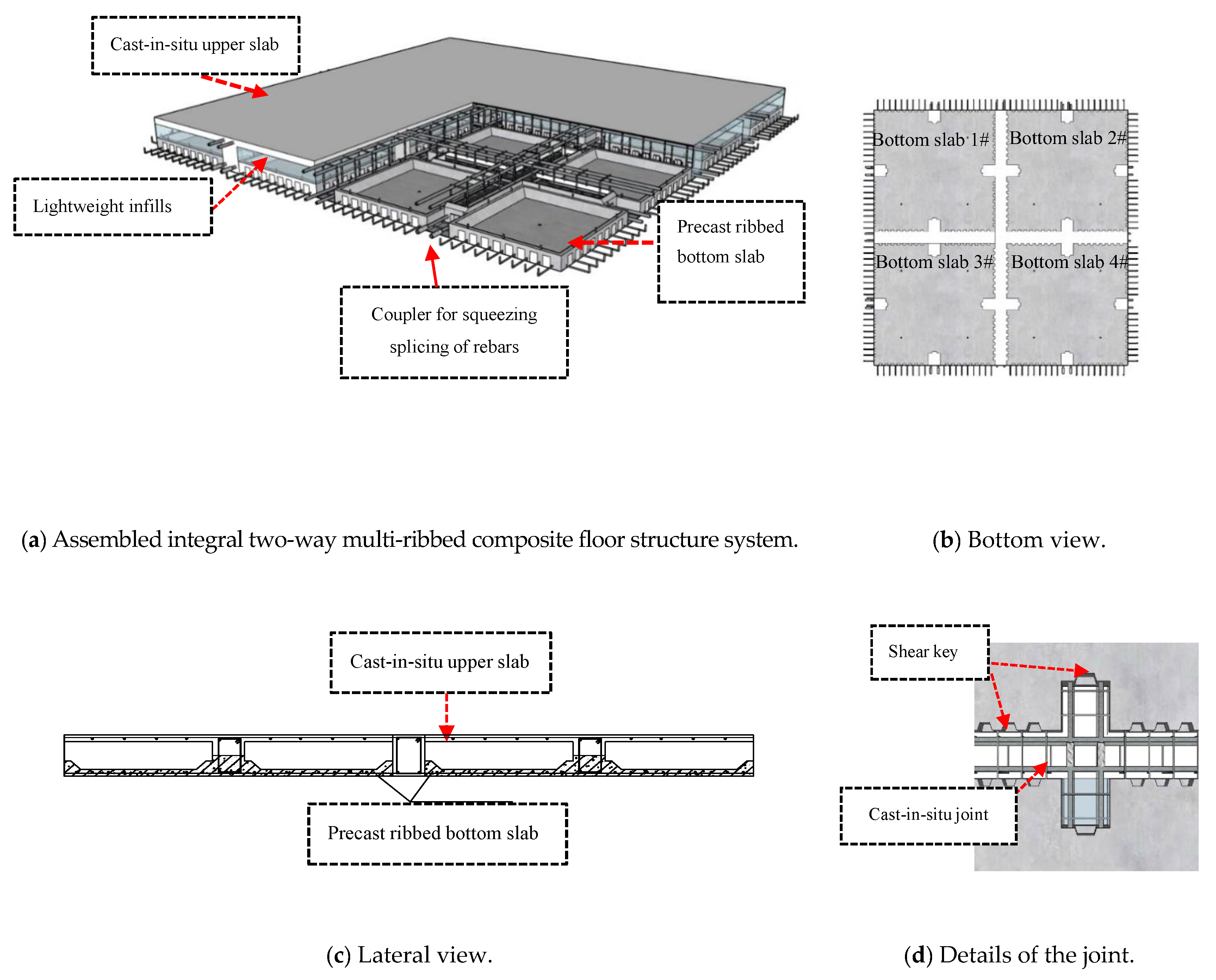
In this paper, a new type of assembled integral two-way multi-ribbed composite floor system is proposed inheriting the advantages of both two-way multi-ribbed floor and composite floor systems. The innovative floor system is composed of four main parts, which are precast ribbed bottom slab (PRBS), lightweight infills, cast-in-situ upper slab (CUS) and joints. The precast ribbed bottom slab is illustrated in Figure 1, where the plane size is 2050 mm × 2050 mm and the thickness is 50 mm. In the middle of the bottom slab there is a 200 mm × 150 mm convex ribbed beam designed in both directions. The ribbed beam is reinforced by two longitudinal rebars and stirrups to undertake the shear force and bending moment, of which the areas of the longitudinal rebars are calculated by analogue beam or analogue slab methods (see JGJ/T 268-2012 [23] “Technical specification for cast-in-situ concrete hollow floor structure”). The bottom slab is reinforced by 8 mm rebar mesh with the spacing of 100 mm in both directions. The extension lengths of the rebar mesh are all 175 mm for binding with adjacent panels. To prevent cracking in demolding, the corners are strengthened with diagonal rebars of 8 mm.
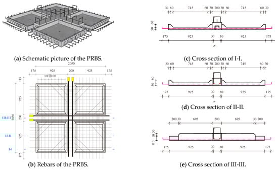
Figure 1.
Precast panels of the assembled integral two-way multi-ribbed composite floor system.
The main function of the lightweight infills is to ensure the hollow cavity and reduce its self-weight. Figure 2 illustrates the detailed sizes of the lightweight infill, which are identical to those of the cavity to ensure there is no concrete penetration in the casting.
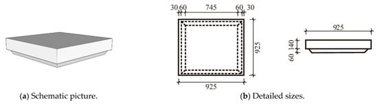
Figure 2.
Lightweight infills of the assembled integral two-way multi-ribbed composite floor system.
With the PRBSs and the lightweight infills arranged, they could serve as lateral and bottom templates for the CUS and joints (see Figure 3). In this way, the hollow ratio and assemble ratio could reach 43% and 87%, respectively, which could bring promising economic and social benefits.
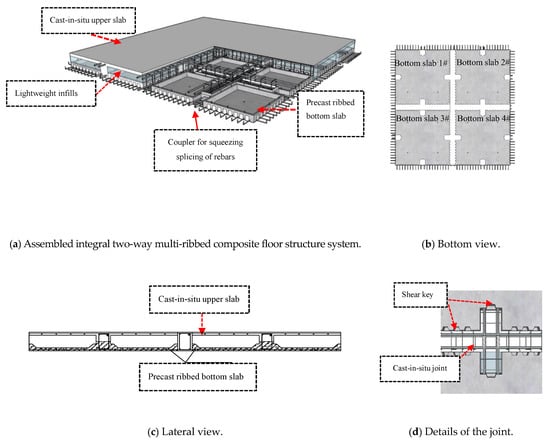
Figure 3.
Schematic picture of the assembled integral two-way multi-ribbed composite floor system.
The three different parts above and adjacent bottom slab are integrated into a reliable system through three methods. (1) The connection between the PRBS and the CUS is realized by the shear strength of the rough interface, cast-in-situ joints and stirrups. (2) The lightweight infills are fixed on the precast bottom slab through the positioning rebars and recessed cavities. (3) The rebars of adjacent PRBSs are connected by couplers for squeezing and splicing of rebars and cast-in-situ joints where there are shear keys equally arranged alongside the outsides of the PRBS.
In order to study the mechanical performance of the assembled integral two-way multi-ribbed composite floor system, a static load test of a 9.2 m × 9.2 m full-scale multi-ribbed composite floor was carried out. The mechanical performance of this floor system in normal service state and maximum design load according to Chinese design code GB50010-2010 were studied. Mechanical performance (i.e., crack distribution, deformation and stress redistribution) were analyzed and compared with finite element method.
2. Experimental Investigation
2.1. Material Properties
Three kinds of material were used in the experiment: steel rod, concrete and coupler for squeezing sleeve spacing of rebars.
Rebars adopted in the experiment were all HRB400, according to Chinese standard GB50010-2010 “Code for design of concrete structures” [24]. The diameters were 6 mm, 12 mm and 20 mm, respectively. The mechanical properties of rebar were tested according to GB228.1-2021 “Metallic materials- Tensile tests- Part 1: methods of test under room temperature” [25], as collected in Table 1.

Table 1.
Mechanical properties of the rebar.
The concrete used in the cast-in-situ columns, beams, PRBC, CUS and cast-in-situ joints were all C35, according to China standard GB50010-2010 [24]. There was a two-month interval between the precast panels and casting-in-situ section, so the two batches of concrete were tested separately. The mechanical properties of the concrete were tested according to GB/T50081-2012 “Standards for test methods of mechanical properties on ordinary concrete” [26], which are summarized in Table 2.
Table 2.
Mechanical properties of the concrete.
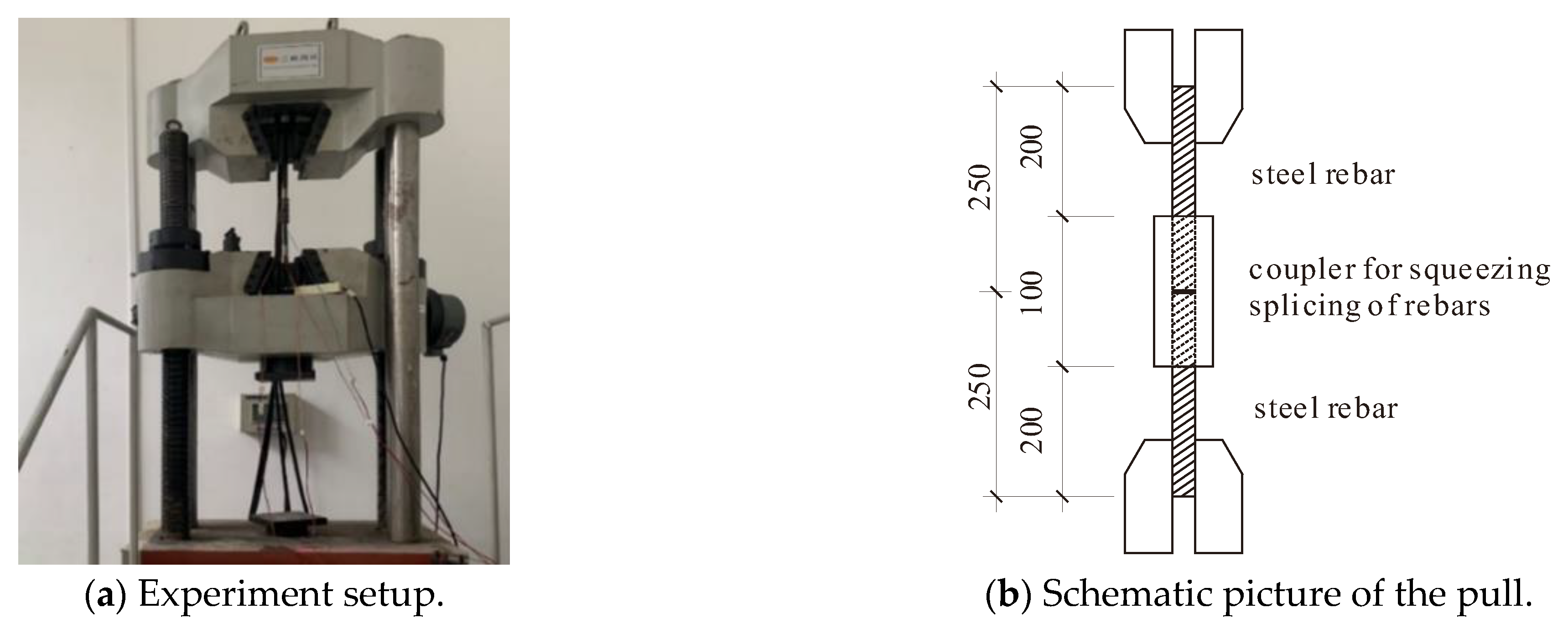
The mechanical properties of the coupler for squeezing and splicing of rebars were tested according to JG/T 163-2013 “Coupler for rebar mechanical splicing” [27], where the tensile experiments were conducted in pull–pull configuration, as presented in Figure 4. Two rebars with a diameter of 20 mm were sleeved into the coupler and connected by cold extrusions. Three replicated cold extrusions are conducted by a hydraulic machine with a pressure of 40 MPa on coupler and rebars of the two ends.
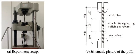
Figure 4.
Tensile test of coupler for squeezing and splicing of rebars.
The tensile tests of the coupler were performed in the laboratory of civil engineering of Southeast University (China). Monotonic loads were applied to the test specimen by a 500 kN hydraulic-servo actuator (MTS, the US) with a speed of 1.0 mm/min. The strain–stress relations are shown in Figure 5, where they are compared with the stress–strain curve of rebars with the same diameter and material. It could be observed that the coupler for squeezing and splicing of rebars shares similar working stages with rebars, such as elastic stage, yield platform and strengthening stage. And the absolute errors of yield and ultimate stress between the rebar and the coupler are less than 5% (see Table 3), so it could be considered that the coupler is a reliable connection method. Further, the coupler could be simulated with the same method of rebars in the finite element method.
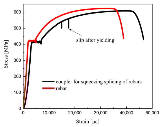
Figure 5.
Stress-strain relationship of coupler for squeezing and splicing of rebars.
Table 3.
Mechanical properties of the coupler.
2.2. Specimen Preparation
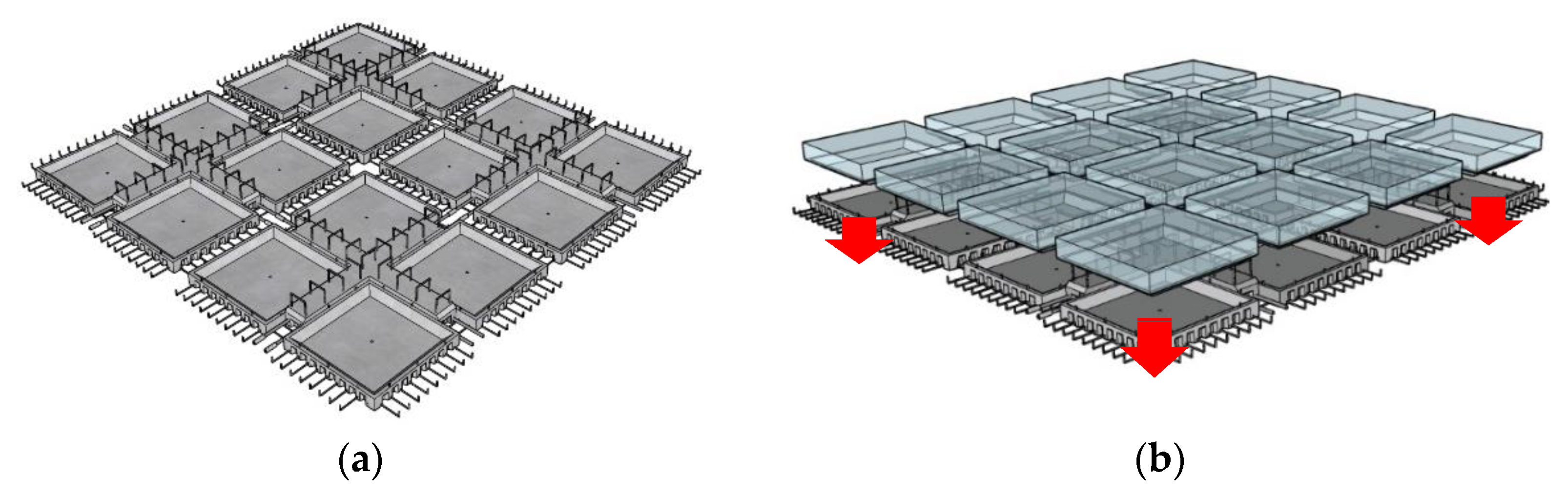
A one-story frame was designed to explore the flexural behavior and working mechanism of the innovative floor system under the designed loads according to GB50010-2010 [24]. The specimen was assembled by 16 precast ribbed bottom slabs and integrated together through CUS, cast-in-situ joints and couplers. The detailed construction process is schematically illustrated in Figure 6 by four precast panels, which encompass mainly three steps. (1) The first step is the location of precast panels and insertion of lightweight infills (see Figure 6a,b). (2) The next step is coupling the longitudinal rebars and rebar mesh of the bottom slab by squeezing and binding, respectively. Rebars of the upper section, such as erection rebars and stirrups of the joints, rebar mesh of the upper slab and rebars in the beams and columns, are also arranged and connected by binding. (3) With all parts above placed, the upper slab, joints, beams and columns are cast, and all prefabricated components are assembled into a two-way floor system. The dimensions of the precast concrete ribbed bottom plate are the same as those in Figure 1, and the concrete beams and columns are reinforced according to the calculation results.

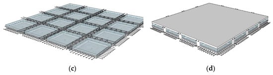
Figure 6.
Construction process of the assembled integral two-way multi-ribbed composite floor system. (a) Location of the precast ribbed bottom slab. (b) Insertion of lightweight infills. (c) Coupling the longitudinal rebars and rebar mesh. (d) Casting.
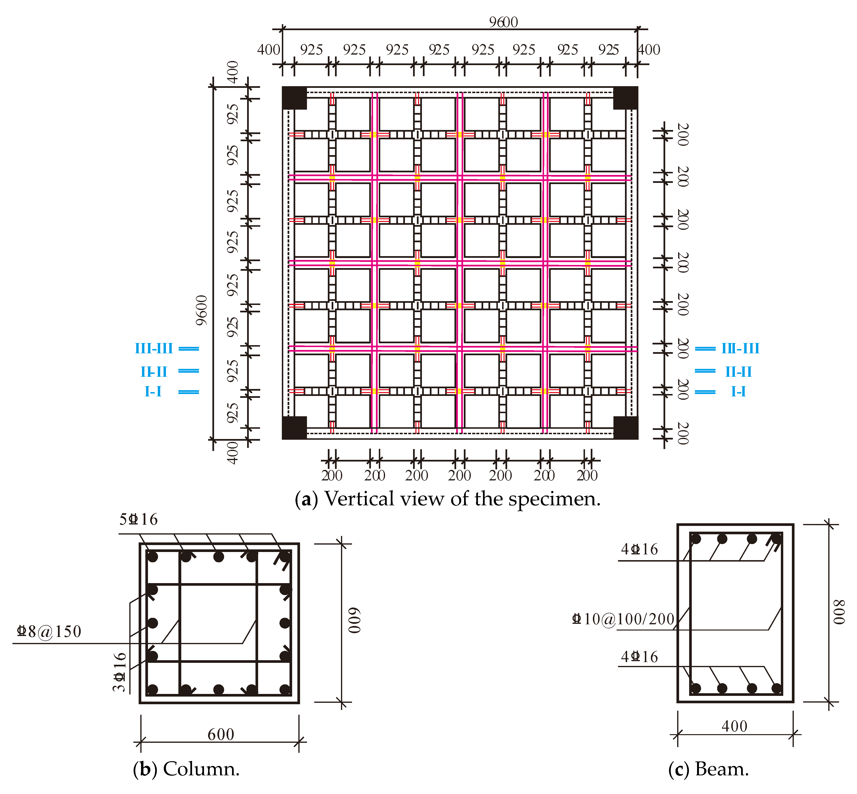
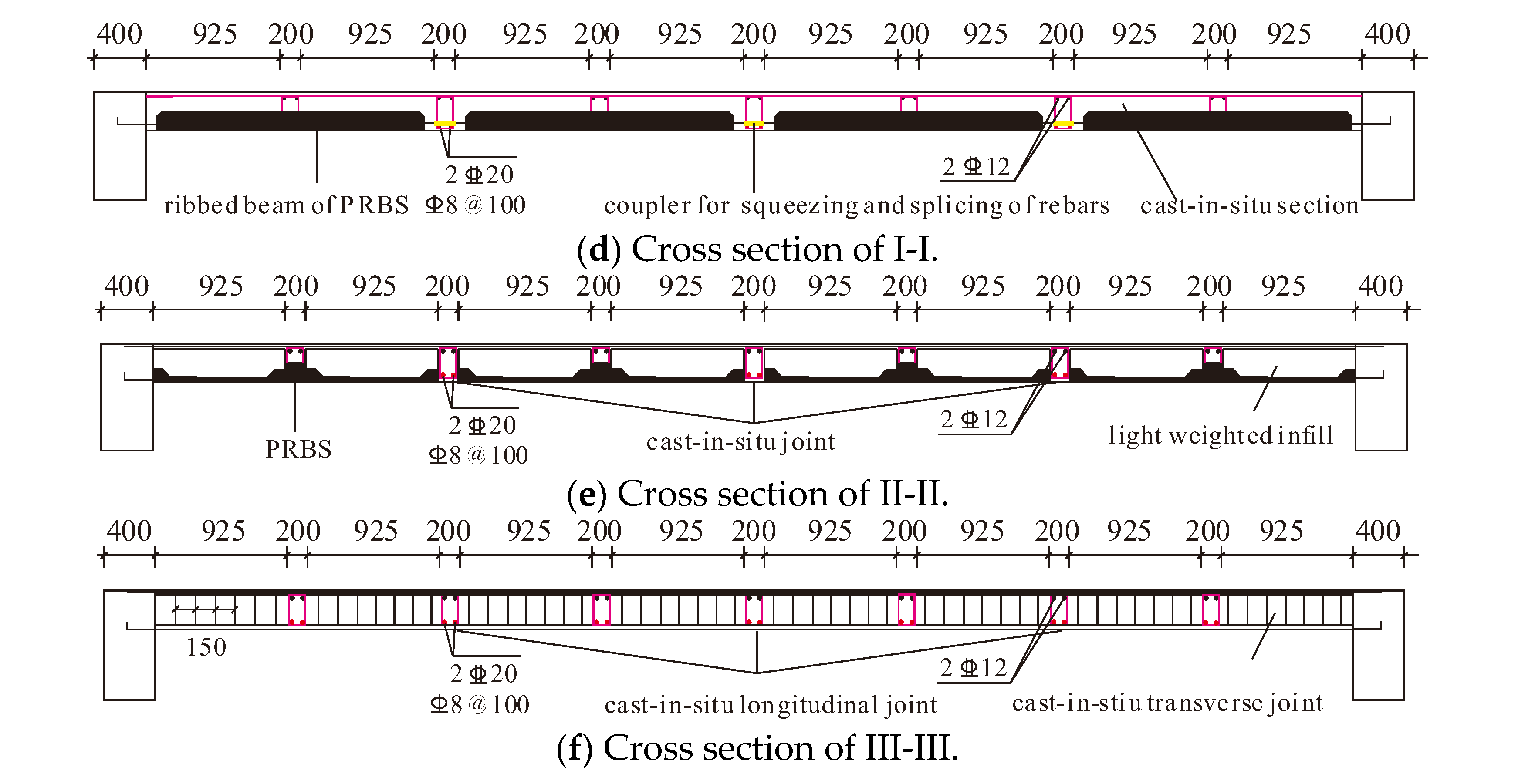
The specimen is presented in Figure 7, which is composed of three different components, i.e., the beams, columns and the assembled integral floor system. The cross section of the four columns is 600 mm × 600 mm, which is designed according to the axial compression ratio in the Chinese code for seismic design of buildings, GB50011-2010 [24]. Four beams with a dimension of 400 mm × 800 mm are employed to support the floor. As illustrated in Figure 7, there are six cast-in-situ RC joints in the floor system, including three transversal joints and three longitudinal joints. The width of the joint is determined to be 200 mm according to the length of reinforcement connection. And the height equals the depth of the floor system, which is 300 mm.
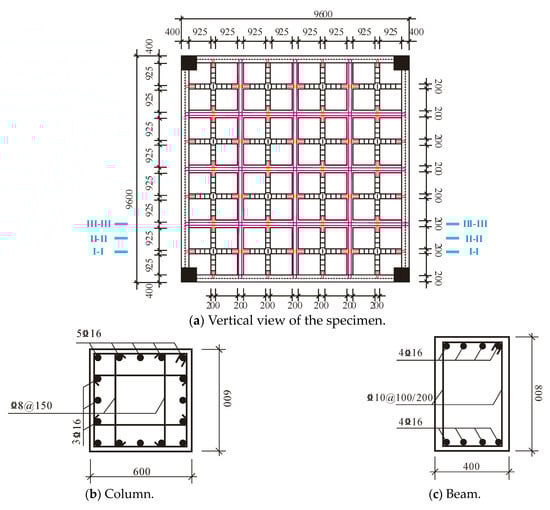
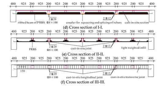
Figure 7.
Detailed sizes of the assembled integral two-way multi-ribbed composite floor system.
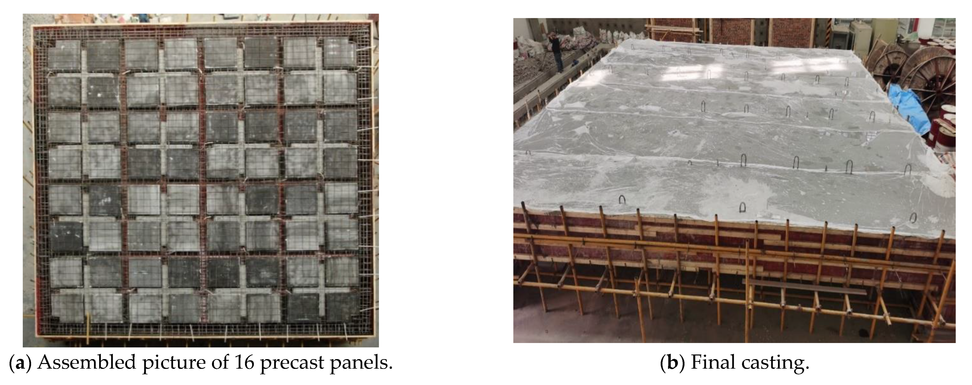
The 16 PRBSs were all manufactured in the factories and the beams, columns, CUS and joints were all poured and cured at the laboratory (as presented in Figure 8), where (a) presents the floor system before casting and (b) is the final casting and curing stage.
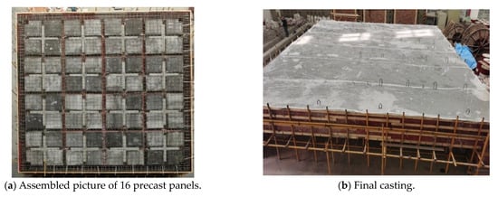
Figure 8.
Tested specimen.
Before the test, white paint and grid were painted on the bottom surface of the floor for the convenience of crack checking in the experiment. The scaffolds were located 100 mm below the bottom of the slab to play a protective role without restricting the free deformation of the floor.
2.3. Load Protocol and Sensor Distribution
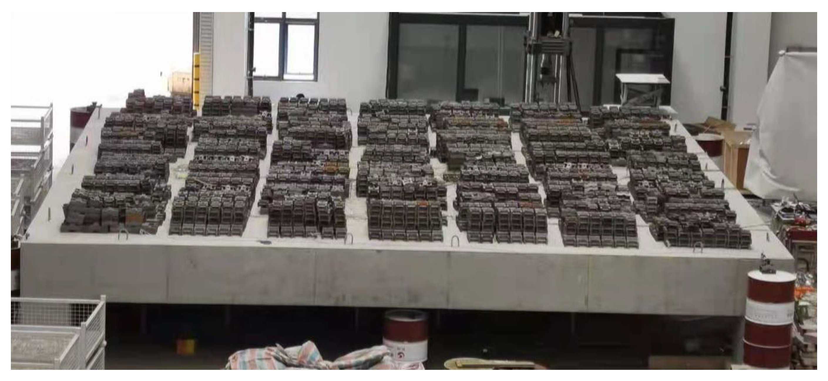
A static load test of the assembled integral two-way multi-ribbed composite floor system was performed in the laboratory of civil engineering of Southeast University (China). Three different kinds of mass blocks were used to exert a uniformly distributed area load on the floor. The average weights of mass blocks were 20 kg, 10 kg and 5 kg, which met the requirements (less than 200 N) of GB/T 50152-2012 “Standard for test method of concrete structures” [28]. The floor was divided into 49 sections with the dimensions of 1.2 m × 1.2 m (see Figure 9), where the mass blocks were evenly stacked. The transversal and longitudinal gaps between each stack of mass blocks were both 10 cm (larger than the demands of GB/T50152-2012 [28]) to avoid the arch effect of large deformation of the specimen.
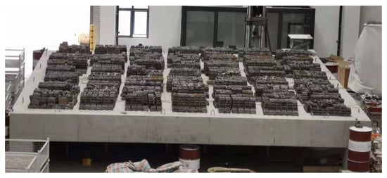
Figure 9.
Area load exerted on the floor system.
The self-weight of the slab is 4.49 kN/m2 and the additional dead load for concrete cement layer and suspended ceiling is calculated as 1.5 kN/m2. According to the Chinese load code for the design of building structures GB50009-2012 “Load Code for The Design of Building Structures” [29], the live load in residential buildings is 2 kN/m2. Thus, the maximum area load and the normal service load of the floor system according to GB50009-2012 could be calculated as 1.3 × Dload + 1.5 × Dlive and 1.0 × Dload + 1.0 × Dlive, which equal 10.79 kN/m2 and 7.99 kN/m2, respectively. Considering the mechanical performance of the floor under 10.79 kN/m2, where detailed information can be found in Section 3.1, the ultimate area load was enhanced to 16.63 kN/m2. The overall weight exerted on the floor is 110 tons, which reaches the limits of the laboratory.
Three loading steps were included in the experiment, i.e., pre-loading, static loading and unloading. (1) Before the start of the static loading, preloading was conducted to check the stability of the structural support and eliminate malfunctioning of instruments and equipment. (2) The static loading conformed to the test methods of GB/T50152-2012, which contained 14 main steps (as presented in Table 4). The load increment of each stage was 0.85 kN/m2, which was about 10% of the designed bearing load of the floor. The maintained time of each load step was 20 min and the data collection and crack description were carried out after the structural deformation became stable. According to GB/T50152-2012 [29], when the accumulated load reached its self-weight, the structure needed to hold the load for at least 12 h. (3) After the test, the mass blocks on the floor were removed in batches, and the cracking of the concrete on the bottom surface of the floor could be observed after complete unloading.
Table 4.
Load protocol of the experiment.
Two different kinds of sensors (i.e., the displacement transducer, the strain gauges) were used during the test.
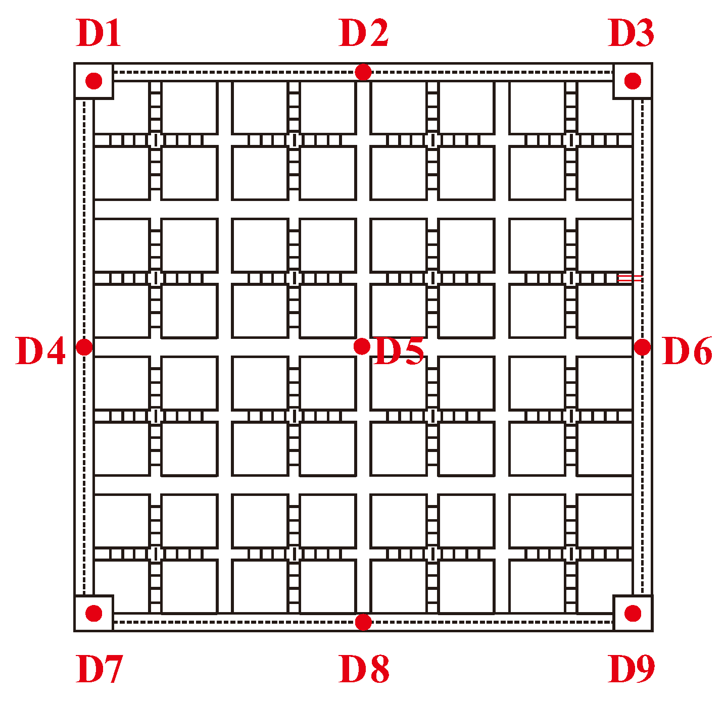
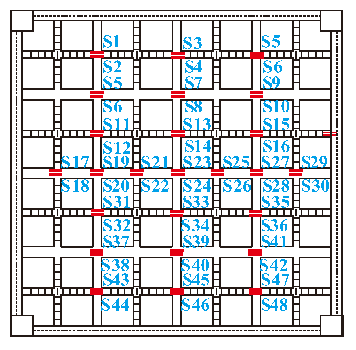
The deformation of the slab was monitored with nine displacement transducers (D1-D9) arranged as shown in Figure 10. The strains of steel bar were all recorded with 2 mm × 1 mm strain gauges. The layout of strain gauges mainly focused on the comparison of strains along the ribbed beam and joints at different positions and their differences with other positions, as presented in Figure 11.
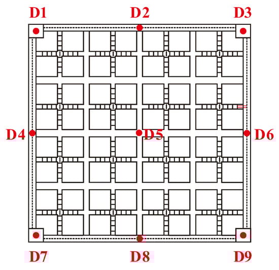
Figure 10.
Arrangement of displacement transducers on the bottom surface.
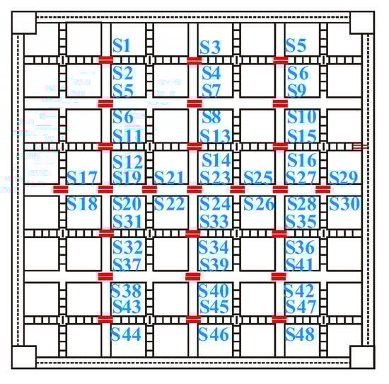
Figure 11.
Layout of the strain gauges on steel bars.
The steel bar strain gauges were fixed on the steel bar before the cast of concrete. Glue and bandages were applied to the steel bar strain gauge and the outer layer of the conductor to avoid damage during concrete pouring.
3. Experimental Results
3.1. Experimental Observation
The deflection and crack development were monitored and logged during the static loads, which were concluded as follows:
In the initial loading stage, the deflection in the middle of the slab increased with the increase of the load linearly, and no cracks were found at other parts of the slab bottom except for some initial fractures. When the load reached 9.83 kN/m2 (the 6th load, accumulated load including its self-weight), a small number of tiny cracks parallel to the direction of the joint appeared on the interface of the new and old concrete. The cracks mainly concentrated in the middle position of the cast-in-situ joints. It is an interesting phenomenon, which will be discussed in the following.
When the floor was exerted with 3.4 kN/m2 (the 4th load), the accumulated area load reached 7.89 kN/m2, which is beyond the service load of GB50010-2010 [24]. There were no cracks and the deflection was only about 2 mm. According to the load protocol, when the additional load reached its self-weight, the experiment was maintained for 24 h. The maximum deflection of the floor increased about 0.5 mm during the maintaining time.
With the load increasing from 9.83 kN/m2 to 12.38 kN/m2, the cracks further developed and the number of cracks increased. It was noticed that the cracks did not extend to the joint or the shear keys. Besides that, the distribution of cracks from the 6th load to the 8th load was not symmetrical and not in the sections with maximum movement. Thus, it was predicted that the cracks of the 6th–8th load were mainly caused by initial defects.
When the floor was exerted with 12.38 kN/m2 (the 9th load), the accumulated area load exceeded the maximum load of GB50010-2010. The maximum strain of steel rebars was only 450 με and the maximum deflection was 5.32 mm, indicating that the floor did not reach its load-carrying capacity. Thus, additional area load should be exerted to explore its mechanical performance.
In the 10th load, the accumulated area load reached 13.23 kN/m2 and diagonal cracks appeared in the middle section of the floor. It is worth noting that the diagonal cracks only developed within one single PRBS. With the area load increased, the length and number of diagonal cracks increased rapidly, which was a distinct difference from the cracks that appeared in 6th to 8th load. Some cracks along the shear key of the PRBS appeared during the 11th load, which was a characteristic and typical phenomenon of the innovative floor system. When the 12th load was exerted, a diagonal crack appeared at the intersection of the floor and column, extending from the column to the mid span direction. As the load increased, the width of cracks along the shear key of the PRBS increased.
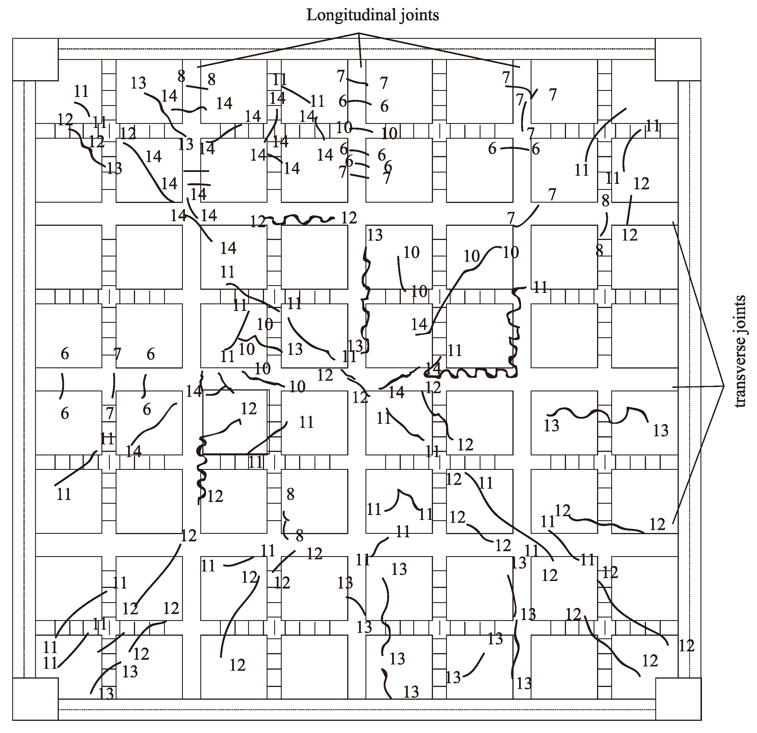
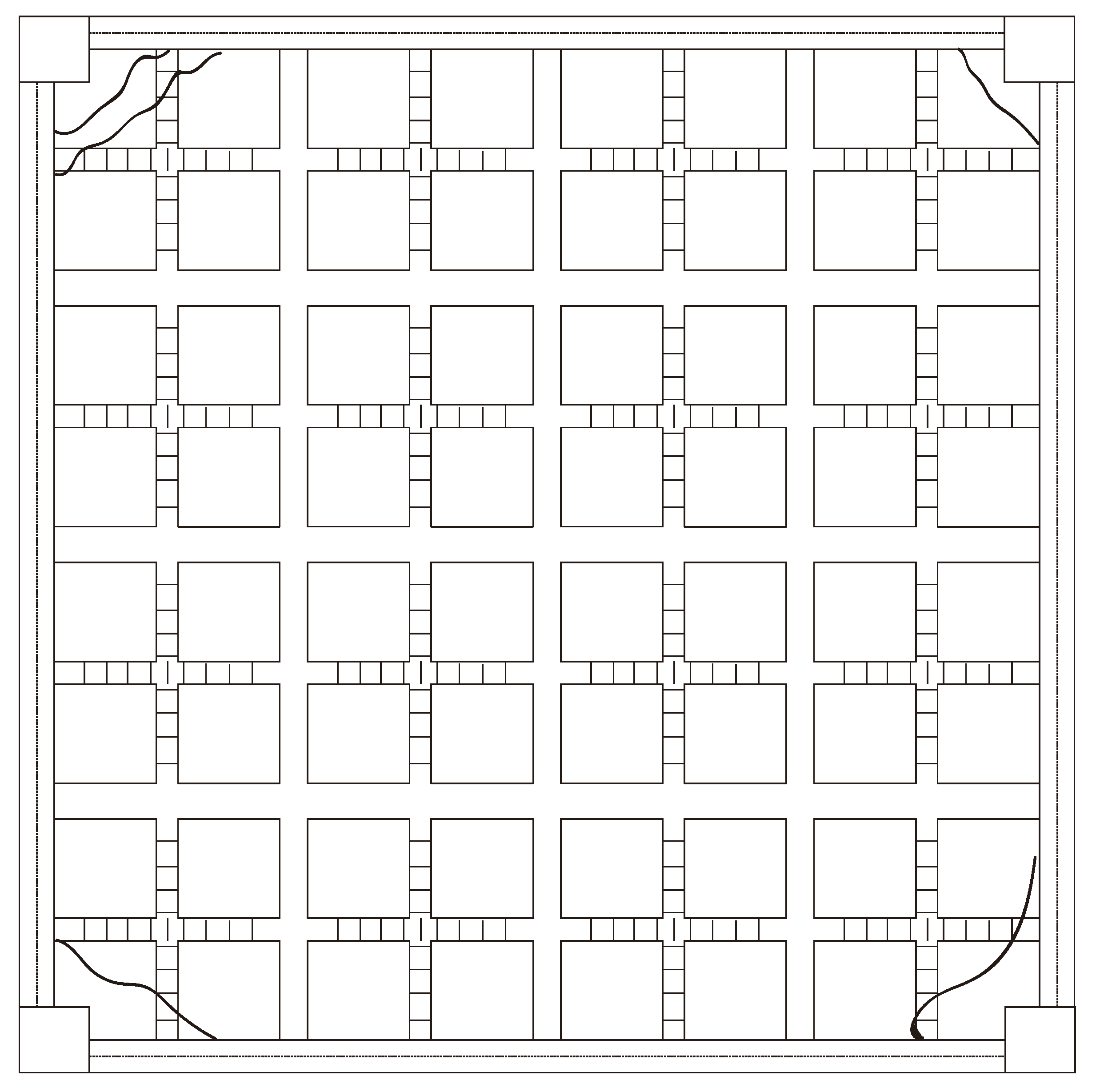
For the 14th load, the cracks concentrated on the ribbed beam of PRBS and joints and the overall shape of cracks turned out to be a “X” shape (see Figure 12 and Figure 13), where the numbers in the figures represented the load grade numbers. And the accumulated area load reached 16.63, which was about 1.5 times the maximum load of GB50010-2010 [24].
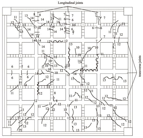
Figure 12.
The cracks on the bottom surface of the floor.
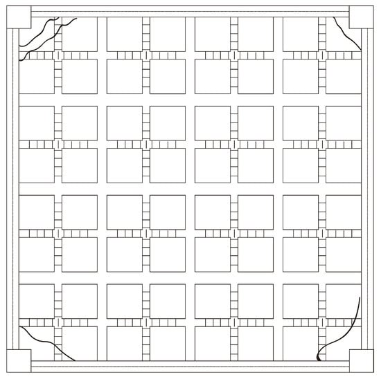
Figure 13.
The cracks on the upper surface of the floor.
3.2. Load–Deflection Relationship
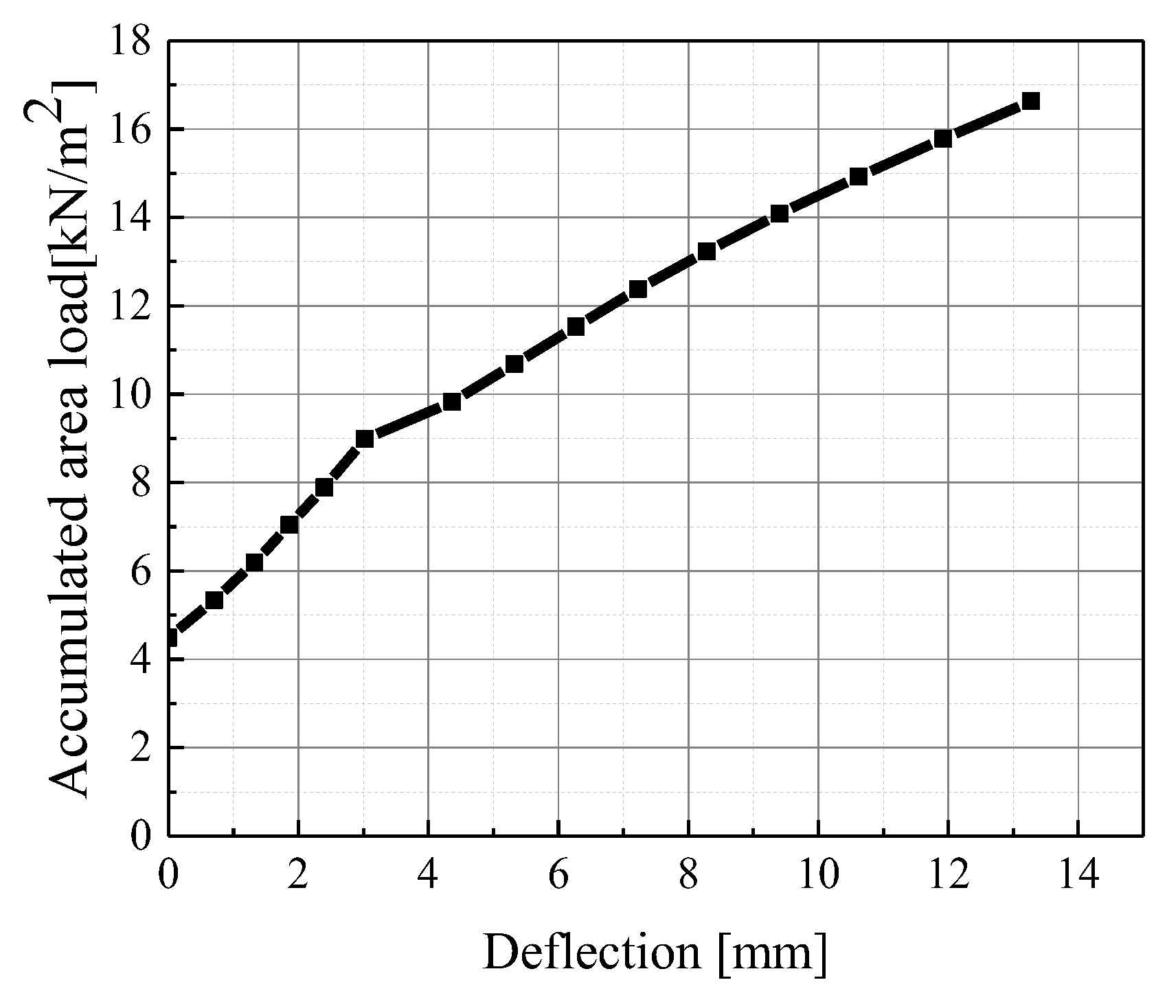
The load–deflection curve of the innovative floor is presented in Figure 14, where the maximum deflection is obtained from D5. According to GB50010-2010, the maximum deflection of normal service load (7.89 kN/m2) should be calculated with the long-term effects, and its deflection limit is L0/300 (L0 is the calculated span of the floor). The maximum deflection was calculated through the displacement sensors D1~D9, as presented in Equation (1).
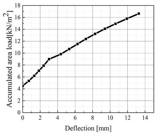
Figure 14.
Load–deflection relationship of the assembled integral two-way multi-ribbed composite floor.
According to the test results, the floor system is still in an elastic state until the 5th level load. And the deflection is measured from 4.49 kN/m2, which is its self-weight. Based on this, it can be concluded that the true deflection under normal service load is 2.40 × (7.99/4.49) = 4.27 mm. According to GB50010-2010 [24], the long-term load correction coefficient is 1.856. The calculated long-term load deflection under normal use load is 7.92 mm, which is less than L0/300 (30.67 mm).
3.3. Stress Distribution
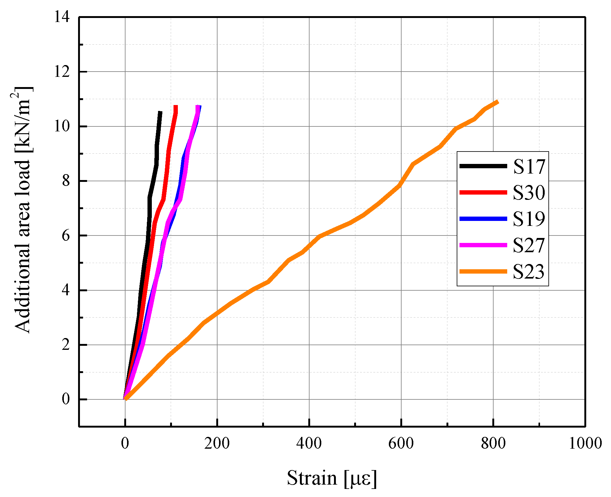
Due to the large number of strain gauges installed in the integral multi-ribbed composite floor, only the representative strain gauges were selected for analysis in this section, and the selected strain gauge locations were strain of the bottom reinforcements according to Figure 11.
It was found that the strain of rebars along one cross section shared identical load–strain configurations. And the maximum value of the strain gauge was still less than 400 με (see Figure 15), indicating the rebars were still in an elastic working state. Even when the test load increased to 1.5 times the designed load of GB50010-2010, the maximum strain was only 800 με.

Figure 15.
Strains of rebar.
4. Finite Element Simulation
Even when the total load of the experiment reached 110 tons, beyond the limits of the laboratory, the floor did not reach the load-carrying capacity. To further study its mechanical behaviors beyond 17 kN/m2, the finite element method turns out to be a supplementary method.
The application of finite element method (FEM) could be explained as follows. First, the calculated results, including load–deflection relationship, stress distribution and failure mode, were compared with the experiment to verify the effectiveness of parameter settings. Then, the finite element model was exerted with a larger area load to explore its nonlinear mechanical behaviors.
The finite element simulation contains six main steps, which are FEM model establishment and meshing, constitutive relationship settings of materials, element selection, contact of different components, load and boundary conditions, analysis steps and calculation.
4.1. Establishment and Meshing of Finite Element Model
A commercial software, ABAQUS 2017 (Dassault Systemes, Paris, France), was utilized to obtain numerical simulation of the assembled integral two-way multi-ribbed composite floor under static load. Due to the sophisticated design of the floor, the FE model was identical to Figure 7 to avoid the influence of oversimplification. The FE model contained four main parts, i.e., the 16 PRBSs, the CUS, cast-in-situ beams and columns, steel rebars, as presented in Figure 16.
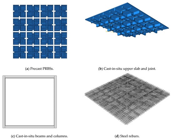
Figure 16.
Finite element model of components in the composite floor.
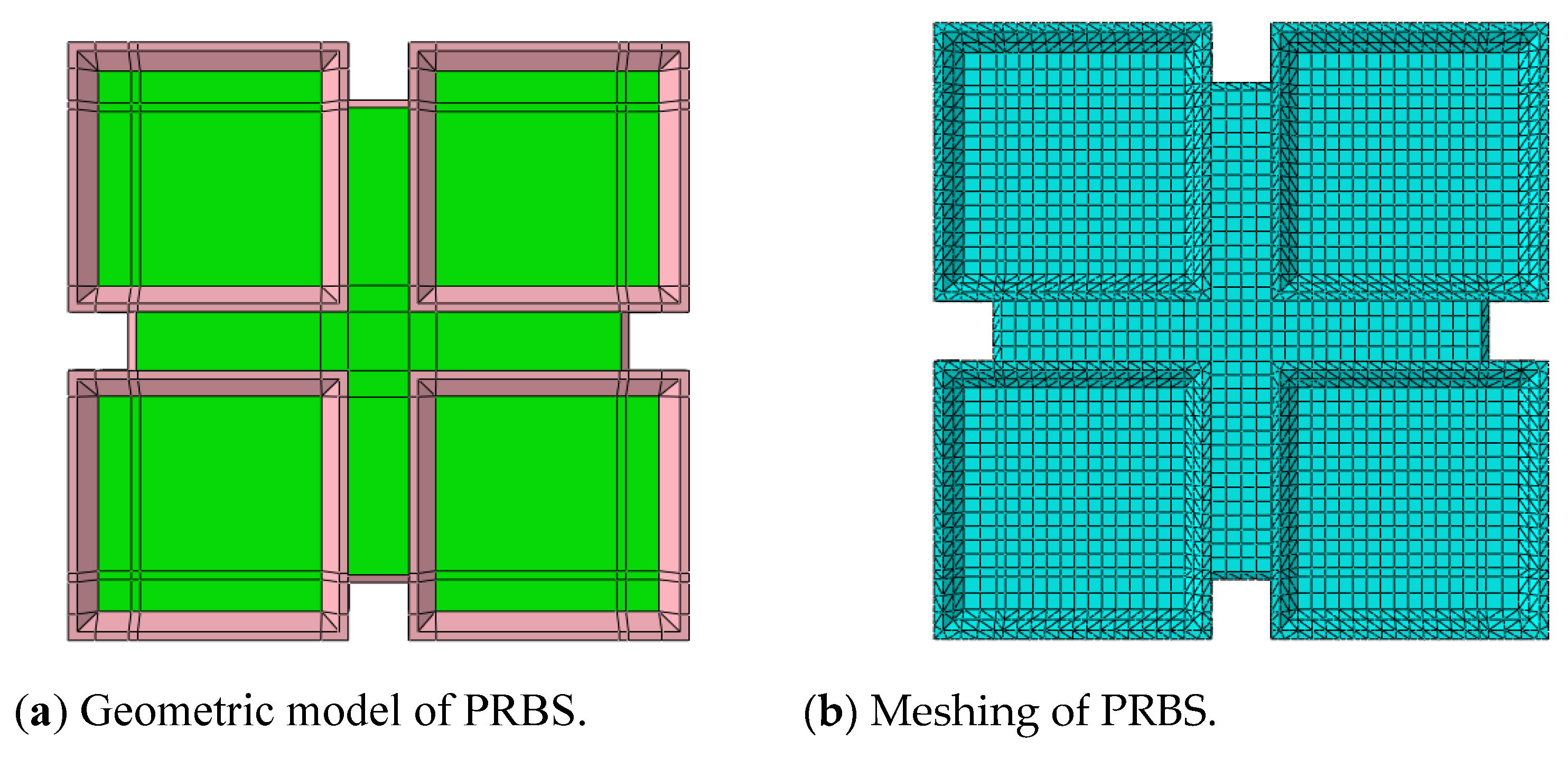
For the extreme geometrical irregularity of precast ribbed bottom slab (PRBS), it was necessary to divide it into two parts when meshing. The green parts indicate it was geometrically regular and could be meshed into a hexahedron, while the pink parts suggest the geometrical irregularity and the need to be meshed into a tetrahedron. From the detailed geometry of Figure 17, it can be easily seen that the pink parts were mainly shear keys around the PRBS and the ends of ribbed beams.
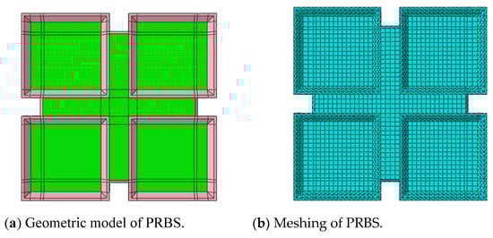
Figure 17.
Geometric model and meshing of the PRBS.
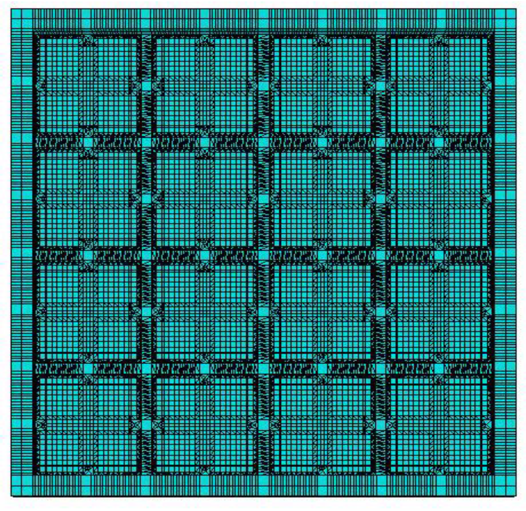
The same meshing methods were applied to CUS and joint. The meshing of the FE model is presented in Figure 18.
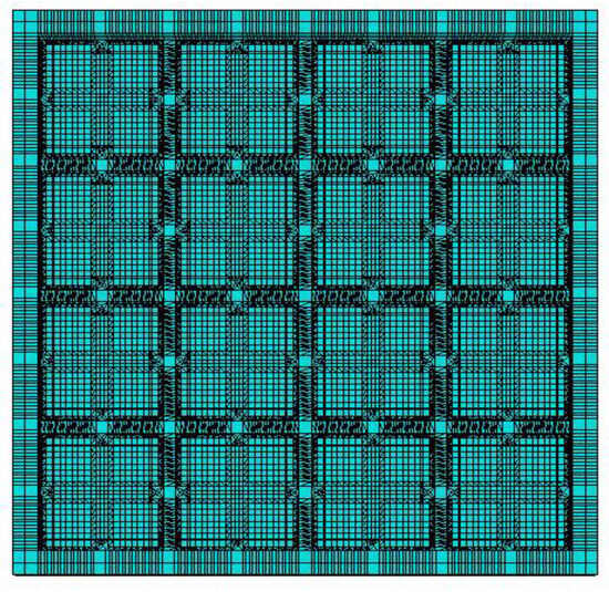
Figure 18.
Finite element model of the assembled integral two-way multi-ribbed composite floor.
4.2. Constitutive Relationship Settings and Element Selection
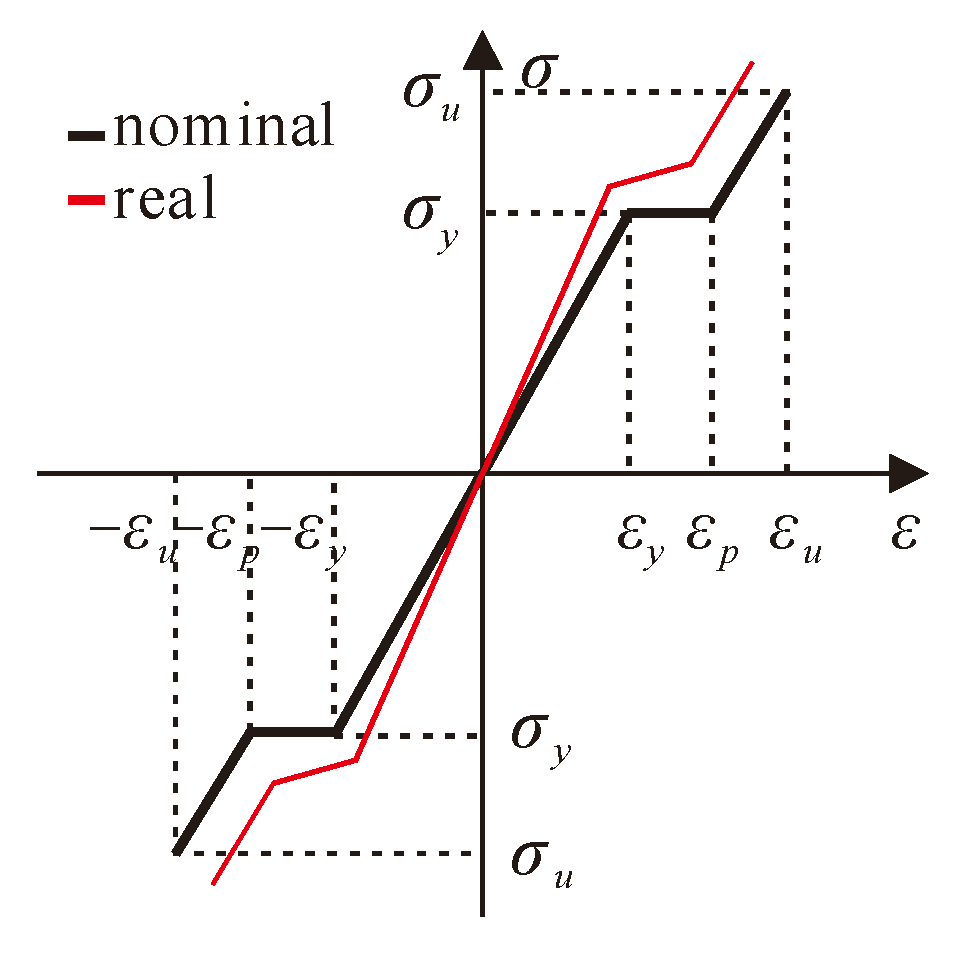
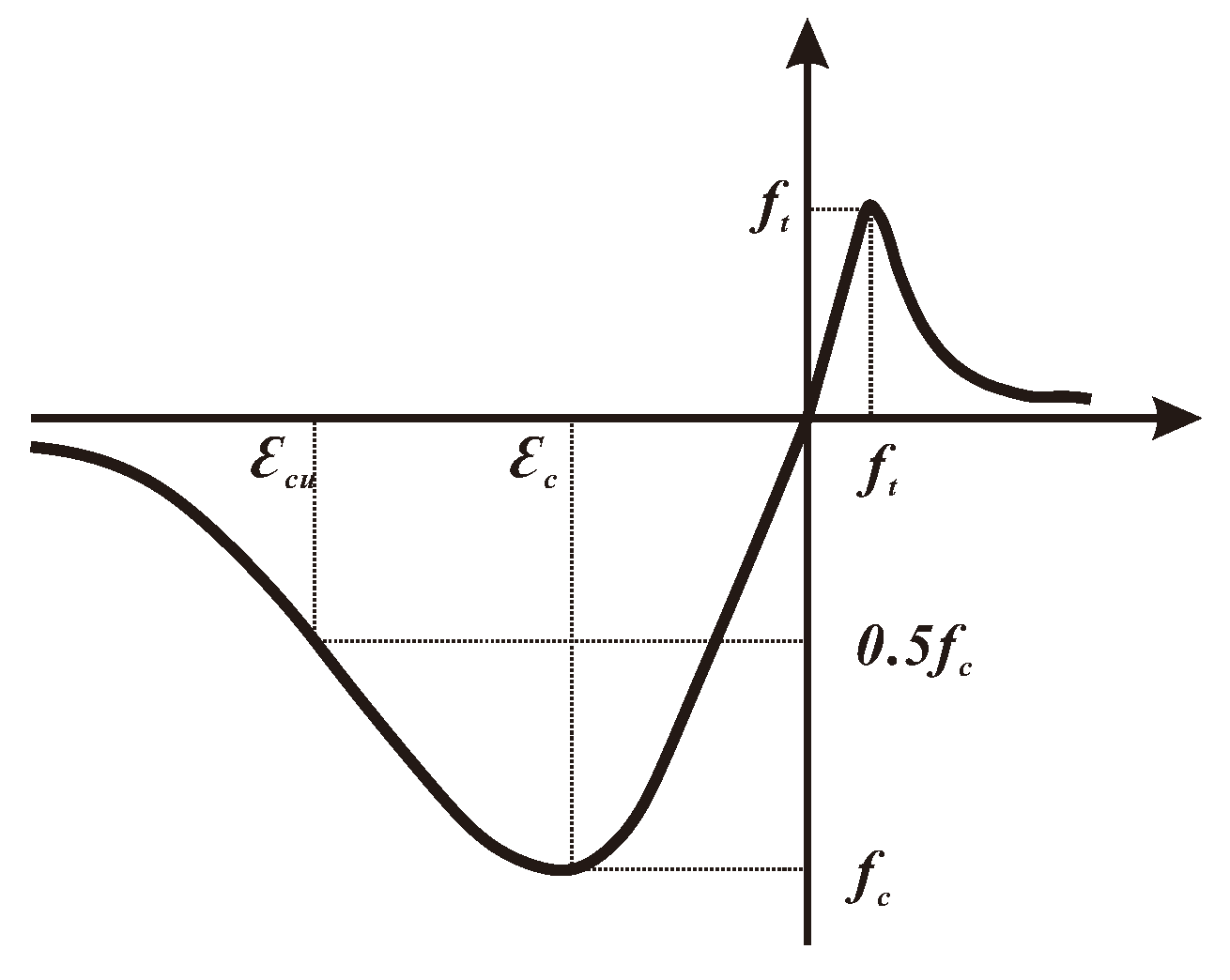
Four different materials were used in the experiment, which were concrete, steel rebar, lightweight infills and coupler for squeezing and splicing of rebars. As previously mentioned, the lightweight infill was designed to ensure the cavity and improve the sound or heat-insulation capabilities of the floor. Thus, its constitutive relationship was not considered when calculating the numerical results. While the behavior of concrete, rebars and coupler might work in the range of elastic-plastic, so the whole life stage, i.e., elastic stage, softening stage and strengthening stage, should be included in the strain–stress relationship. Figure 19 and Figure 20 illustrate the stress and strain relations of concrete and steel bars, respectively. The nominal strain and stress were calculated by Equations (2) and (3), where and were the real strain and stress of rebars, and were the nominal strain and stress of rebars obtained from the experiment in Table 1 and Table 3.
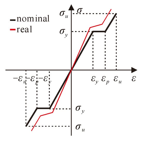
Figure 19.
The strain–stress relationship of steel bars [20].
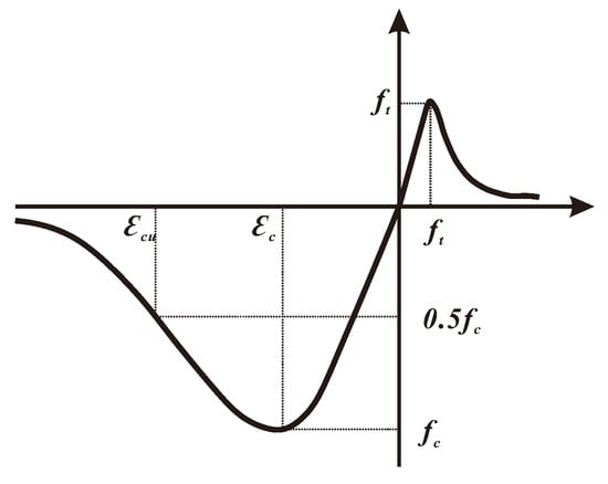
Figure 20.
Strain–stress relationship of concrete [24].
The element type of C3D8R (three-dimensional eight-node linear brick elements with reduced integration) in ABAQUS was chosen to simulate the geometrically regular part. The geometrically regular part was simulated by C3D10 (three-dimensional ten-node quadratic tetrahedron) element. The rebars were all simulated by T3D2 (three-dimensional two-node truss) element.
4.3. Contact and Boundary Conditions
The contact surface mainly included two different categories: (1) the direct contact between the upper surface of the PRBS and the CUS and (2) the contact of the shear key round the PRBS and cast-in-situ joint, which was connected through rebars and squeezing. Considering the connection types, the former contact relationship was set as a tie. For the latter one, the contact relationship of the normal direction was set as “hard contact”, and the tangential direction was set as “penalty friction”. Boundary conditions were identical with the experiment.
4.4. Load and Analysis Steps
According to the load protocol, the specimen was divided into 49 sections, where mass block was evenly stacked to simulate the area load. The same division method and area load were applied on the upper surface of the FE model.
The calculation contains two load procedures, which were self-weight and additional area loads. The maximum area load was set as 60 kN/m2 to fully investigate its nonlinear behaviors. The solver of “static general” in ABAQUS was selected to calculate its numerical results.
4.5. Simulation Results Analysis and Load-Carrying Capacity Calculation
4.5.1. Simulation Results
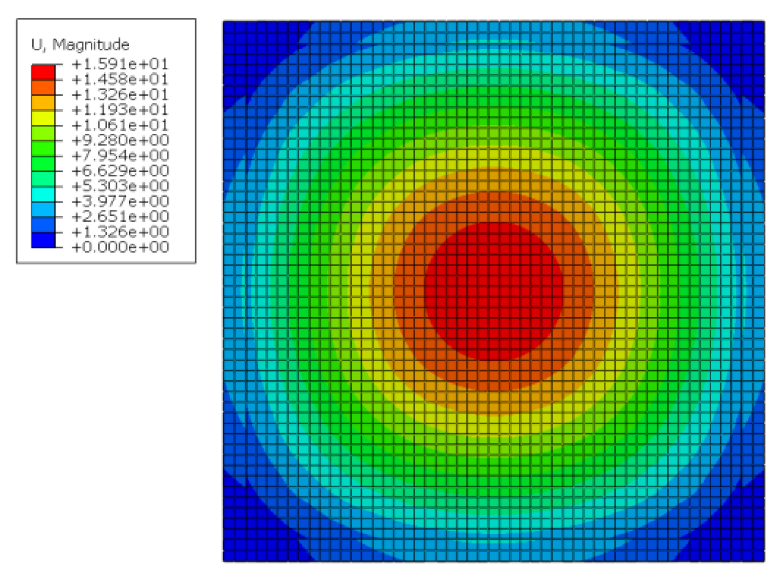
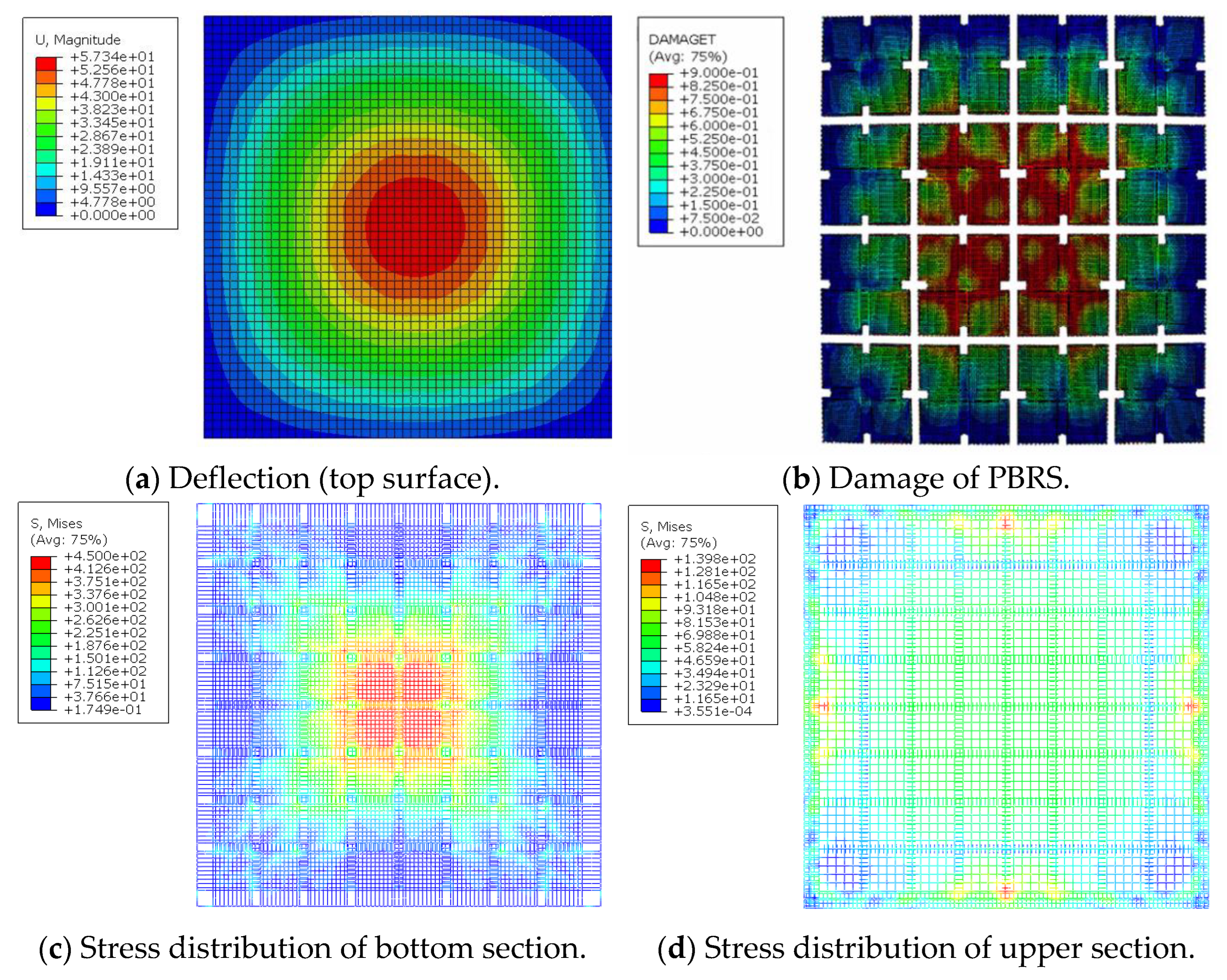
Figure 21 and Figure 22 show the displacement and stress distribution of the assembled integral two-way multi-ribbed composite floor system under an area load of 16 kN/m2 (including the self-weight of the floor). The mid span deflection of the floor was 15.91 mm, and the absolute error of the experimental and finite element results was 7.86%.

Figure 21.
Deflection of the innovative floor system (top surface).
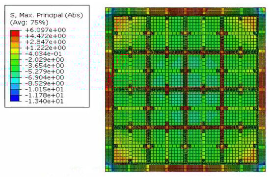
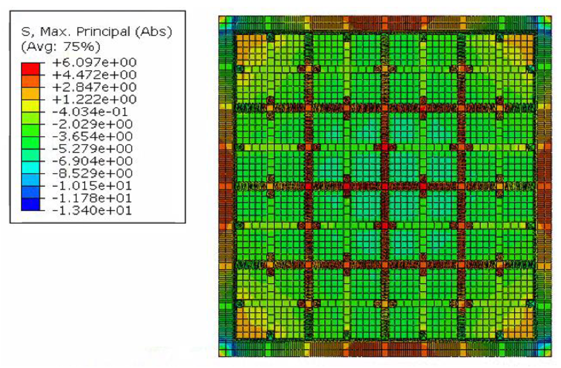
Figure 22.
Stress distribution of the innovative floor system (bottom surface).
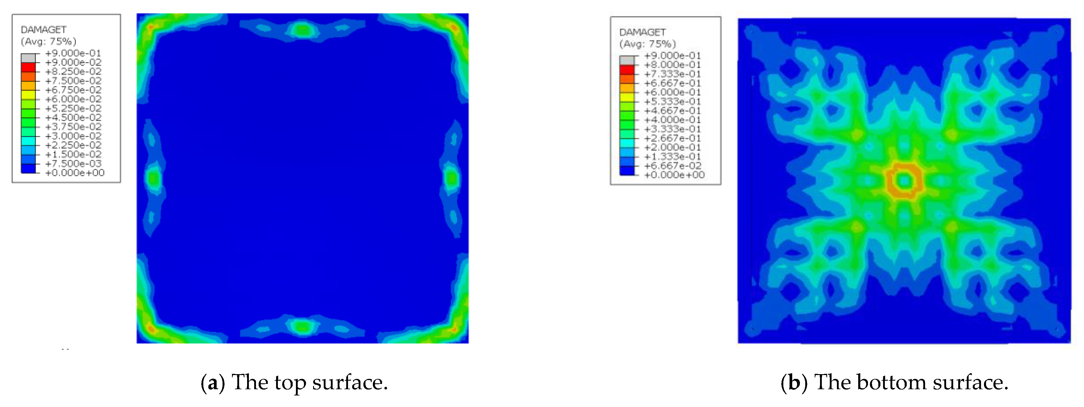
To further compare the crack distribution, a parameter “DAMAGET” was selected to represent the degree of tensile damage of the assembled integral two-way multi-ribbed composite floor system in ABAQUS. The calculation method of DAMAGET at a specific strain ε1 is explained as Equation (4) [20], where E0 represents the original undamaged Young’s modulus of concrete, f(ε) is the stress function of a specific node and stands for the strain energy at the given stress. The range of DAMAGET is within [0,1], indicating the extent of damage of materials. When the concrete works in elastic stage, the strain energy equals and DAMAGET could be calculated as zero. For elements undergoing nonlinear behaviors, the stiffness degrades and the accumulated strain energy is less , resulting a larger DAMAGET.
It could be found from the maximum damage factor of the bottom surface mainly focused on the central four PRBSs, which was similar to results of Figure 12. Comparison of DAMAGET at the top and bottom surface of the assembled integral two-way multi-ribbed composite floor system and the experimental results are summarized in Figure 23. The distribution of concrete damage was in an “X” shape, which was basically consistent with the crack distribution in the experiment. The simulation results showed that the damage in the middle of the floor slab is the largest, which is also consistent with the phenomenon observed in the experiment.

Figure 23.
Damage of top and bottom surface.
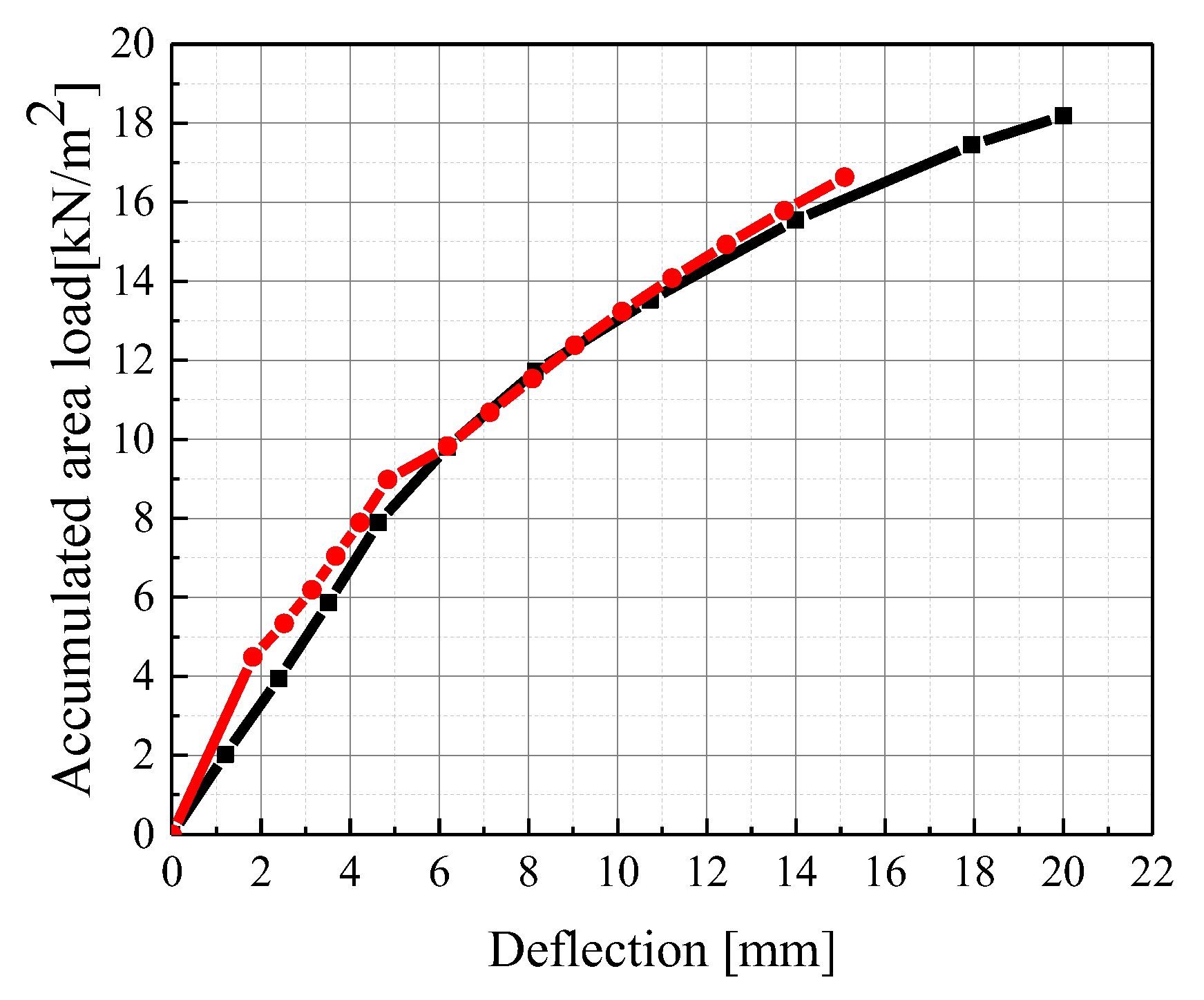
Figure 24 shows the comparison of the load–deflection curves between finite element analysis and testing. The trends of the two curves are basically consistent, and both include two working stages: elastic working stage, where the entire cross-section worked together without cracks. When cracks appear, the stiffness decreased, and as the cracks gradually increased, the stiffness continued to decrease. The maximum mid span deflection error of the two curves was less than 10%, within the acceptable range.
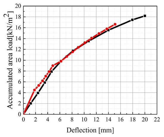
Figure 24.
Comparison of load-deflection relationship between experiment and finite element simulation.
4.5.2. Load-Carrying Capacity Calculation
From the comparison above, it could be found that the finite element simulation could efficiently simulate the mechanical performance of the assembled integral two-way multi-ribbed composite floor system.
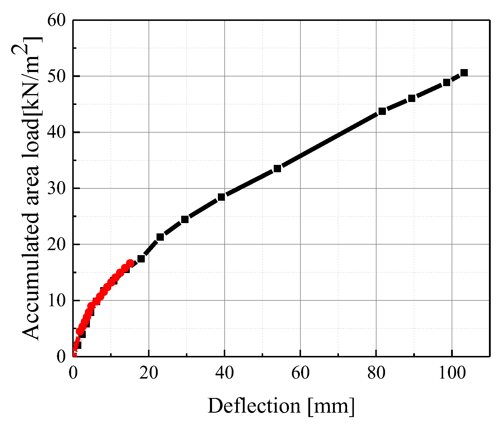
To furtherly study its load-carrying capacity, the area load when the rebars yield (i.e., reach 400 MPa) was defined as its load-carrying capacity. Based on the same finite element model above, a larger area load was applied and the ultimate load obtained was 50.98 kN/m2. The calculation results of this model are shown in Figure 25 and Figure 26.
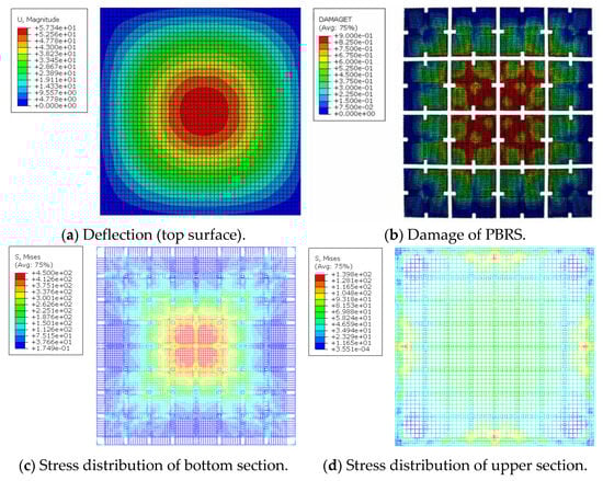
Figure 25.
Simulation results of load-carrying capacity.

Figure 26.
Comparison of load–deflection relationship between experiment and finite element simulation with a larger area load.
4.5.3. Error Discussion
As illustrated in Figure 26, it is evident that the finite element simulation is consistent with the experiment. In the overall configuration, the trend of the finite element simulation and experimental results in the initial stage were basically consistent. With the area load increases, its deflection exhibited more obvious nonlinearity.
But there were still some errors in both load–deflection relationship and failure mode. They mainly came from three aspects. (1) The finite element method ignored the squeezing between the elements and resulted in deviation from the actual deformation. (2) The reinforcement was simulated by truss elements embedded in the concrete, where the bond-slip relationship between the two materials was not considered in the simulation. (3) There were construction defects that could not be precisely simulated. The absolute error was within the acceptable range.
In summary, the finite element modeling method based on this section could serve as an effective tool for studying the ultimate bearing capacity of a new type of assembled integrated bidirectional multi-ribbed composite floor, further compensating for the limitations of experimental conditions.
5. Conclusions
This paper presents a new type of assembled integral composite floor system, which is composed of precast ribbed bottom slab, lightweight infills, cast-in-situ upper slab and joints. To study the overall mechanical performance of the innovative floor system, a specimen with a size of 9.2 m × 9.2 m was designed and simulated in ABAQUS. Mechanical performance involving the load–deflection relationship, crack distribution and load-carrying capacity were analyzed. The following conclusions can be drawn:
- (1)
- The assembled integral two-way multi-ribbed composite floor system met the requirements of normal service load and maximum designed load according to GB50010-2010. Under normal use load (7.89 kN/m2), the long-term deflection of the floor was 7.92 mm, meeting the limit value of deflection L0/300 under normal use limit state. Under the maximum design load of GB50010-2010, the maximum strain of longitudinal rebar at the bottom of the slab was 450 μɛ, indicating that key structural components do not reach the ultimate bearing capacity.
- (2)
- The crack mainly concentrated on the joint position and the cracks under 16.63 kN/m2 turned out to be “X-shaped”. At this point, the strain of the longitudinal load-bearing steel bars had not yet yielded, proving that the new floor is of sufficient safety redundancy.
- (3)
- The finite element method could serve as an effective tool for studying the ultimate bearing capacity of a new type of assembled integrated bidirectional multi-ribbed composite floor. The absolute error between the experiment and the finite element simulation is less than 10%, and the load-carrying capacity of the floor system is 50.98 kN/m2.
Author Contributions
Conceptualization, X.Z. and M.X.; Methodology, Y.F. and M.X.; Software, Y.F. and S.R.; Validation, Y.F.; Formal analysis, M.X.; Investigation, S.R.; Resources, L.G.; Writing—original draft, L.G.; Writing—review & editing, S.R.; Visualization, S.R. and L.G.; Supervision, M.X.; Project administration, X.Z.; Funding acquisition, X.Z. and M.X. All authors have read and agreed to the published version of the manuscript.
Funding
This research received no external funding.
Data Availability Statement
The XLSX data used to support the findings of this study may be accessed by emailing the corresponding author, who can be contacted at xuming@seu.edu.cn.
Acknowledgments
The study was supported by the Basic Science (Natural Science) Research Project of Higher Education Institutions in Jiangsu Province, 23KJA560006. Their support is gratefully acknowledged.
Conflicts of Interest
The authors declare that there are no conflict of interest regarding the publication of this paper.
References
- Ding, D. Calculation of Reinforced Concrete Floor; Press of Science and Technology: Shanghai, China, 1954. (In Chinese) [Google Scholar]
- Safar, A.; Lou, K.B. A study of the action of the beam and beamless (flush) floor slabs of the multistorey buildings. Erciyes Univ. Fen Bilim. Enstitüsü Fen Bilim. Derg. 2007, 23, 127–135. [Google Scholar]
- Newmark, N.M. Proposed design specifications for two-way floor slabs. J. Proc. 1950, 46, 597–607. [Google Scholar]
- Nilson, A.H.; Walters, D.B. Deflection of two-way floor systems by the equivalent frame method. J. Proc. 1975, 72, 210–218. [Google Scholar]
- Idrus, A.B.; Newman, J.B. Construction related factors influencing the choice of concrete floor systems. Constr. Manag. Econ. 2002, 20, 13–19. [Google Scholar] [CrossRef]
- Hegger, J.; Roggendorf, T.; Teworte, F. FE analyses of shear-loaded hollow-core slabs on different supports. Mag. Concr. Res. 2010, 62, 531–541. [Google Scholar] [CrossRef]
- Abramski, M.; Schnell, J.; Albert, A.; Pfeffer, K. Experimental and numerical investigation of the bearing behaviour of hollow core slabs. Beton Stahlbetonbau 2010, 105, 349–361. [Google Scholar] [CrossRef]
- de Lima Araújo, D.; Sales, M.W.R.; Silva, R.P.M.; Antunes, C.D.F.M.; de Araújo Ferreira, M. Shear strength of prestressed 160 mm deep hollow core slabs. Eng. Struct. 2020, 218, 110723. [Google Scholar] [CrossRef]
- Jiang, Q.; Zhang, K.; Feng, Y.; Chong, X.; Huang, J. Out-of-plane flexural behavior of full precast concrete hollow core slabs with lateral joints. Struct. Concr. 2020, 21, 2433–2451. [Google Scholar] [CrossRef]
- Xuhong, Z.; Wei, C.; Fangbo, W.; Hailin, H.; Jiyuan, L. Study on stiffness of assembled monolithic concrete hollow floor with two-way ribs. J. Build. Struct. 2011, 32, 75. [Google Scholar]
- Wang, S.C.; Wang, C.S.; Wang, Q.; Tian, X.F.; Duan, L. Flexural behaviors of full-scale prestressed concrete hollow slab girders with composite strengthening. J. Traffic Transp. Eng. 2018, 18, 31–41. [Google Scholar]
- Khairussaleh, N.M.; Omar, R.; Aris, S.M.; Nor, M.M.; Saidi, M.M.; Mahari, N.N.M. Flexural Behaviour of the Two-Way Spanning Reinforced Concrete Slab Using Spherical Plastic Bubble Balls. IOP Conf. Ser. Earth Environ. Sci. 2023, 1140, 012016. [Google Scholar] [CrossRef]
- Morcous, G.; Henin, E.; Fawzy, F.; Lafferty, M.; Tadros, M.K. A new shallow precast/prestressed concrete floor system for multi-story buildings in low seismic zones. Eng. Struct. 2014, 60, 287–299. [Google Scholar] [CrossRef]
- Huang, Y.; Ma, K.; Zhang, H.; Xiao, J.; Jiang, S. Study and Application of Vierendeel-Sandwich-Plate Floor Framing in Multistoried and Tall Building. J. Build. Struct. 1997, 18, 55–64. [Google Scholar]
- Pan, Y. Study of Load-bearing Properties of PK Prestressed Composite Slab. Master’s Thesis, University of Hunan, Changsha, China, 2009. (In Chinese). [Google Scholar]
- Niu, W. Experimental and Theoretical Study on Waffle Hollow-Core Composited Floor. Master’s Thesis, University of Hunan, Changsha, China, 2009. (In Chinese). [Google Scholar]
- Pang, R. Research on the Mechanical Property and Seismic Design Method of New Type Precast RC Diaphragms. Master’s Thesis, Southeast University, Nanjing, China. (In Chinese).
- Naito, C.J.; Cao, L.; Peter, W. Precast Concrete Double-tee Connections, Part I: Tension Behavior. PCI J. 2009, 54, 49–66. [Google Scholar] [CrossRef]
- Spadea, S.; Rossini, M.; Nanni, A. Design analysis and experimental behavior of precast concrete double-tee girders prestressed with carbon-fiber-reinforced polymer strands. PCI J. 2018, 63, 72–84. [Google Scholar] [CrossRef]
- Gong, L.; Chen, Z.; Feng, Y.; Ruan, S.; Tu, L. Experimental Study on an Innovative Hollow Concrete Floor System Assembled with Precast Panels and Self-Thermal-Insulation Infills. Adv. Civ. Eng. 2021, 2021, 6663412. [Google Scholar] [CrossRef]
- Fertigteil-Vertrieb, G.; Mannheim, B.-Z. Reinforced Concrete Cellular Plate for One-way and Two-way Stress Directions for High Loads and Large Span. Eng. Des. Broch. 1965, 35, 351–354. [Google Scholar]
- Fahmy, E.H.; Shaheen, Y.B.I.; Zeid, M.N.A.; Gaafar, H.M. Ferrocement sandwich and hollow core panels for floor construction. Can. J. Civ. Eng. 2012, 39, 1297–1310. [Google Scholar]
- JGJ/T 268-2012; Technical Specification for Cast-In-Situ Concrete Hollow Floor Structure. China Architecture & Building Press: Beijing, China, 2012.
- GB 50010-2010; Code for Design of Concrete Structures. China Architecture & Building Press: Beijing, China, 2017.
- GB/T 228.1-2010; Metallic Materials–Tensile Testing—Part 1: Method of Test at Room Temperature. Standards Press of China: Beijing, China, 2022.
- GB/T50081-2012; Standards for test methods of mechanical properties on ordinary concrete. China Architecture & Building Press: Beijing, China, 2019.
- JG/T 163-2013; Coupler for Rebar Mechanical Splicing. Standards Press of China: Beijing, China, 2013.
- GB/T 50152-2012; Standard for Test Method of Concrete Structures. China Architecture & Building Press: Beijing, China, 2012.
- GB 50009-2012; Load Code for The Design of Building Structures. China Architecture & Building Press: Beijing, China, 2016.


Disclaimer/Publisher’s Note: The statements, opinions and data contained in all publications are solely those of the individual author(s) and contributor(s) and not of MDPI and/or the editor(s). MDPI and/or the editor(s) disclaim responsibility for any injury to people or property resulting from any ideas, methods, instructions or products referred to in the content. |
© 2023 by the authors. Licensee MDPI, Basel, Switzerland. This article is an open access article distributed under the terms and conditions of the Creative Commons Attribution (CC BY) license (https://creativecommons.org/licenses/by/4.0/).