Article

Two-Way Time-Dependent Prestress Losses of Prestressed Concrete Containment with Bonded Prestressing Strands

School of Civil Engineering, Dalian University of Technology, Dalian 116024, China
*
Author to whom correspondence should be addressed.
Buildings 2023, 13(10), 2513; https://doi.org/10.3390/buildings13102513
Submission received: 11 September 2023 / Revised: 30 September 2023 / Accepted: 2 October 2023 / Published: 4 October 2023
(This article belongs to the Section Building Materials, and Repair & Renovation)

Abstract

:
Prestressing plays a pivotal role in ensuring the tightness and integrity of prestressed concrete containment in nuclear power plants. The prestress loss reduces the compressive stress in concrete resulting from the prestressing strands and increases the risk of containment leakage under severe accident conditions. Therefore, the accurate prediction of prestress loss is essential for the design and in-service management of prestressed concrete containment. Unlike one-way beams or girders in building structures and bridges, two-way prestressing systems are used in prestressed concrete containment. In the current simplified method for evaluating time-dependent prestress loss, the interaction of concrete creep in two directions resulting from the two-way prestressing strands and the influence of the steel liner and mild steel rebars in two directions are neglected. In this study, based on the principle of creep superposition, the age-adjusted effective method for the creep estimation of concrete, and considering concrete shrinkage, concrete creep, and the relaxation of prestressing strands, as well as the influence of the steel liner and mild steel rebars in two directions, a sectional analysis is performed for prestressed concrete containment with bonded prestressing strands, and equations for calculating the two-way time-dependent prestress losses are derived. The results of the two-way time-dependent prestress losses predicted by the derived equations are compared with those of tests in the literature, and great agreement is achieved. Finally, a case study is given to show the application of the proposed method for the prediction of prestress loss in prestressed concrete containment in the nuclear power plant.

1. Introduction

The nuclear containment structure is the outermost protective building of the nuclear reactor in nuclear power plants, which serves as the ultimate physical barrier in the defense-in-depth system of nuclear power plants [1]. The prestressed concrete containment is composed of horizontal and vertical prestressing strands, mild steel rebars, a steel liner, and concrete. The role of prestressing is to keep the concrete in compression during the life span of the containment and to prevent the leakage of radioactive material into the external environment under overpressure accident conditions. However, owing to the inherent nature of shrinkage and creep of concrete and the relaxation of prestressing strands, compressive stress in the concrete of the prestressed concrete containment deceases with time, resulting in a higher risk of leakage of radioactive substances in severe accidents. Thus, time-limited aging analysis and the accurate evaluation of prestress loss are of importance for the design and in-service management of prestressed concrete containment.
Up to now, a large number of studies have been conducted on the time-dependent evaluation of prestress loss. Guo et al. [2] proposed an improved model for predicting time-dependent prestress loss considering non-prestressed steel and the interaction among the shrinkage, creep of concrete, and stress relaxation loss. Yang et al. [3] proposed a prediction model of long-term prestress loss with consideration of the coupling effect of shrinkage and creep of concrete, prestressing steel relaxation, and the presence of non-prestressing steel, as well as the corrosion of prestressing and non-prestressing steel, and proposed a probability analysis method for long-term prestress loss considering the uncertainties of calculation parameters and models. And some studies [4,5] developed dynamic or static nondestructive methods for prestress loss identification. In addition, several studies have focused on the prediction of time-dependent prestress loss of the prestressed concrete containment. Considering the importance of precision of concrete creep models in predicting the prestress loss of prestress concrete containment, both the early-age and hardened concrete made of type V cement were examined through tests by Song and Kim [6] and compared with the predicted results of creep-prediction equations in several design specifications as well as the Bažant and Panula’s model [7]. Cai et al. [8] proposed a standard method of time-limited aging analysis of grouted prestressed concrete containment by means of the results of site investigation and finite element analysis. Lundqvist and Nilsson [9] compared the prestress losses obtained from in-service inspections and those estimated using several prediction models for creep, shrinkage, and relaxation in design codes in an attempt to increase the accuracy of the models and modified the existing expressions for the development of shrinkage using the findings on the humidity and temperature inside two Swedish containments. Bílý et al. [10] verified the usability of Bǎzant’s B3T shrinkage and creep model of concrete for elevated temperatures of containment by comparing the real-world measurements gathered from publicly available sources for 13 types of containment (31 structures in total) with B3T model predictions. Anderson [11] indicated the suitability of the advanced and current commonly used models for predicting prestress loss in design codes by measuring the prestress loss up to 30 years after the tensioning of six Swedish reactor containments. Accounting for the variation in concrete stress during prestressed tensioning and long-term service, Yang et al. [12] carried out a theoretical analysis and numerical simulation to investigate the prestress loss of prestressed concrete containment of nuclear power plants based on the age-adjusted effective modulus method and assess the internal pressure bearing capacity of the prestressed concrete containment in long-term service. Zhang et al. [13] performed finite element analysis to predict the long-term prestress loss of prestressed concrete containment by incorporating the concrete shrinkage and creep functions established by genetic programming based on the Infrastructure Technology Institute of Northwestern University database into a general finite-element software package. Based on the results of the finite element analysis prediction, they proposed three long-term prestress loss prediction models by utilizing the artificial neural network (ANN), one-dimensional convolutional neural network (1D CNN), and genetic programming (GP). Hu and Lin [14] performed a study on the impact of prestress loss on the ultimate pressure capacity and the failure mode of the pressurized water reactor (PWR) prestressed concrete containment based on numerical analysis using the Abaqus finite element program. In addition, considering the measuring error of prestress loss in-service inspection and the randomness of time-dependent properties of materials in theoretical analysis, several studies [15,16,17,18] highlighted the probabilistic analysis and simulation of prestress losses of prestressed concrete containment in the nuclear power plant.
Although extensive research has been carried out for the prediction of prestress loss of prestressed concrete containment, further study is still necessary. The available methods for the prediction of prestress loss of prestressed concrete containment can be categorized into simplified and sophisticated ones. For the sophisticated method, it is often necessary to perform finite element analysis to obtain accurate calculations, but it is more time-consuming. In addition, the concrete creep model from the design specification needs to be converted to Kelvin chain format (Pony series) prior to analysis. For the simplified method, the analysis is based on the equations of prestress loss in design codes [19,20] and ignores the influence of the steel liner and mild steel rebars in two directions, as well as the interaction of concrete creep resulting from the two-way prestressing strands (see Figure 1). However, some studies [1,21] have found that the presence of mild steel rebars affects the stress distribution in the structure and thus may have a significant impact on the time-dependent prestress losses. At the same time, the presence of the steel liner and the interaction of prestress in two directions of the prestressed concrete containment also limit the deformation of the concrete and affect the time-dependent prestress losses. Based on the above-mentioned background, a method for evaluating the prestress loss of prestressed concrete containment is presented in this study, accounting for the influence of the steel liner and mild steel rebars in two directions and the interaction of concrete creep resulting from the two-way prestressing strands. The results calculated using the proposed method are compared with those of the creep tests of two-way prestressed concrete. Finally, a case study is provided to show the application of the proposed method for prediction of prestress loss of prestressed concrete containment in the nuclear power plant. It should be noted that the proposed method applies to the prediction of prestress loss of prestressed concrete containment with bonded prestressing strands because the plane section hypothesis in section analysis is used in the derivation of the equations in this study.

2. Three Conditions for Viscoelastic Analysis

The stress complex regions such as large openings and structural discontinuities in prestressed concrete containment are generally referred to as singular regions, while the remaining areas can be referred to as regular segments [22]. Figure 2 shows an element picked from the regular segment of the prestressed concrete containment shown in Figure 1, where A s x and A s z are the cross-sectional areas of the steel liner in the x-direction and z-direction, respectively; A s x 1 and A s x 2 are the total areas of the inner and outer steel rebars in the x-direction in the containment, respectively; A s z 1 and A s z 2 are the total areas of the inner and outer steel rebars in the z-direction in the containment, respectively; A p x and A p z are the total areas of the prestressing tendons in the x-direction and z-direction in the containment, respectively; N s x ( t ) and N s z ( t ) are the total axial forces of the steel liner in the x-direction and z-direction, respectively; N s x 1 ( t ) and N s x 2 ( t ) are the total axial forces of the inner and outer steel rebars in the x-direction in the containment, respectively; N s z 1 ( t ) and N s z 2 ( t ) are the total axial forces of the inner and outer steel rebars in the z-direction in the containment, respectively; and N p x t and N p z ( t ) are the total tensile forces of the prestressing tendons in the x-direction and z-direction in the containment, respectively.
It should be noted that the regular segment in the prestressed concrete containment is a cylindrical shell. However, the circumferential curvature of a small element on the regular segment varies very slightly, which can be treated as a flat plate. In this way, it is not necessary to consider the effect of the circumferential curvature, which is the same as the calculation of steel rebars in the regular segment.
The instantaneous prestress losses in the containment are related to the jacking and transfer time of prestressing tendons. Although not all prestressing tendons in the containment are jacked and transferred at the same time, it is assumed for the sake of simplicity of analysis that the transfer process is finished at a single time t 0 , which can be taken as the midpoint between the time of transfer of the first prestressing tendon and the time of transfer of the last prestressing tendon. At this point, the total axial forces of the steel liner in the x-direction and z-direction are N s x ( t 0 ) and N s z ( t 0 ) , respectively; the total axial forces of the inner and outer steel rebars in the x-direction in the containment are N s x 1 ( t 0 ) and N s x 2 ( t 0 ) , respectively; the total axial forces of the inner and outer steel rebars in the z-direction in the containment are N s z 1 ( t 0 ) and N s z 2 ( t 0 ) , respectively; and the total tensile forces of the prestressing tendons in the x-direction and z-direction in the containment are N p x t 0 and N p z ( t 0 ) , respectively.
According to the general viscoelastic theory, the internal forces and deformations of a small element need to satisfy the static equilibrium, physical, and deformation compatibility conditions.

2.1. Static Equilibrium Conditions

Starting from time t 0 , when the transfer process is completed, the stresses in concrete, steel rebars, and prestressing tendons of the element of concern vary with the shrinkage, creep of the concrete, and relaxation of the prestressing tendons, and the increments in the internal forces and moment in x- and z- directions in the section of the element hold in equilibrium:
Δ N c x ( t , t 0 ) + Δ N s x ( t , t 0 ) + N s x 1 ( t , t 0 ) + Δ N s x 2 ( t , t 0 ) + Δ N p x ( t , t 0 ) = 0
Δ M c x ( t , t 0 ) + Δ N s x 1 ( t , t 0 ) e s x 1 + Δ N s x 2 ( t , t 0 ) e s x 2 + Δ N p x ( t , t 0 ) e p x = 0
Δ N c z ( t , t 0 ) + Δ N s z ( t , t 0 ) + N s z 1 ( t , t 0 ) + Δ N s z 2 ( t , t 0 ) + Δ N p z ( t , t 0 ) = 0
Δ M c z ( t , t 0 ) + Δ N s z 1 ( t , t 0 ) e s z 1 + Δ N s z 2 ( t , t 0 ) e s z 2 + Δ N p z ( t , t 0 ) e p z = 0
where Δ N c x ( t , t 0 ) and Δ N c z ( t , t 0 ) are the increments in forces of concrete in the x-direction and z-direction, respectively; Δ M c x ( t , t 0 ) and Δ M c z ( t , t 0 ) are the increments in the bending moment of concrete in the x-direction and z-direction, respectively; Δ N s x t , t 0  and Δ N s z ( t , t 0 ) are the increments in axial forces of steel liners in the x-direction and z-direction, respectively; Δ N s x 1 t , t 0 and Δ N s x 2 t , t 0 are the increments in axial forces of the inner and outer steel rebars in the x-direction, respectively; Δ N s z 1 t , t 0  and Δ N s z 2 t , t 0 are the increments in axial forces of the inner and outer steel rebars in the z-direction, respectively; Δ N p x t , t 0 and Δ N p z ( t , t 0 ) are the increments in axial forces of prestressing tendons in the x-direction and z-direction, respectively; and e s x , e s z , e s x 1 , e s z 1 , e s x 2 , e s z 2 , e p x , and e p z are the eccentricities of the steel liner, inner and outer steel rebars, and prestressing tendons in the x-direction and z-direction of the containment element relative to the centroid of the element, respectively, which can be calculated by e s x 1 = y s x 1 y c , e s x 2 = y s x 2 y c , e p x = y p x y c ; e s z 1 = y e z 1 y c , e s z 2 = y e z 2 y c , and e p z = y p z y c (referring to Figure 2) assuming the distance from the edge to the centroid in both the x-direction and z-direction is y c .
Furthermore, Equations (1)–(4) can be expressed in terms of stress increments of steel rebars and prestressing tendons using Equations (5)–(8):
Δ N c x ( t , t 0 ) + A s x Δ σ s x ( t , t 0 ) + A s x 1 Δ σ s x 1 ( t , t 0 ) + A s x 2 Δ σ s x 2 ( t , t 0 ) + A p x Δ σ p x ( t , t 0 ) = 0
Δ M c x ( t , t 0 ) + A s x Δ σ s x ( t , t 0 ) e s x + A s x 1 Δ σ s x 1 ( t , t 0 ) e s x 1 + A s x 2 Δ σ s x 2 ( t , t 0 ) e e x 2 + A p x Δ σ p x ( t , t 0 ) e p x = 0
Δ N c z ( t , t 0 ) + A s z Δ σ s z ( t , t 0 ) + A s z 1 Δ σ s z 1 ( t , t 0 ) + A s z 2 Δ σ s z 2 ( t , t 0 ) + A p z Δ σ p z ( t , t 0 ) = 0
Δ M c z ( t , t 0 ) + A s z Δ σ s z ( t , t 0 ) e s z + A s z 1 Δ σ s z 1 ( t , t 0 ) e s z 1 + A s z 2 Δ σ s z 2 ( t , t 0 ) e e z 2 + A p z Δ σ p z ( t , t 0 ) e p z = 0
where Δ σ s x ( t , t 0 ) and Δ σ s z ( t , t 0 ) are the increments in normal stresses of steel liners in the x-direction and z-direction, respectively; Δ σ s x 1 t , t 0 and Δ σ s x 2 t , t 0 are the increments in stresses of the inner and outer steel rebars in the x-direction, respectively; Δ σ s z 1 t , t 0 and Δ σ s z 2 t , t 0 are the increments in stresses of the inner and outer steel rebars in the z-direction, respectively; and Δ σ p x ( t , t 0 ) and Δ σ p z ( t , t 0 ) are the increments in stresses of prestressing tendons in the x-direction and z-direction, respectively.

2.2. Physical Conditions

Prestressed concrete containment elements are subjected to forces in two directions, and the deformation of concrete in both directions is interacted with through Poisson’s effect on concrete. Hence, Poisson’s ratio needs to be taken into account in the analysis of the two-way time-dependent prestress loss. Several studies have been conducted on the variation in Poisson’s ratio of concrete with time, and some researchers [23,24,25] found that the creep Poisson’s ratio varies with time under load. Others [26,27,28,29,30] observed that the creep Poisson’s ratio of concrete remains roughly constant and is sensibly independent of stress history, regardless of loading age or load-holding duration. Gopalakrishnan et al. [29] and Meyer [30] found that the creep Poisson’s ratio of concrete varies in the range between 0.17 and 0.20 and between 0.16 and 0.25, respectively, which is substantially equal to the elastic Poisson’s ratio under basic creep conditions. For the convenience of calculation, it is generally assumed that Poisson’s ratio of concrete does not vary with time [31]. In this study, the creep Poisson’s ratio is taken as 0.2, which is a constant equal to the elastic Poisson’s ratio. In this way, the time-dependent stress–strain relationship for concrete, based on the Boltzmann superposition principle, is as follows:
Δ ε c x ( t , t 0 , y ) = φ ( t , t 0 ) E c ( t 0 ) σ c x ( t 0 , y ) μ c σ c z ( t 0 , y ) + t 0 t J ( t , τ ) d Δ σ c x ( τ , y ) μ c Δ σ c z ( τ , y ) + Δ ε s h ( t , t s , t 0 )
Δ ε c z ( t , t 0 , y ) = φ ( t , t 0 ) E c ( t 0 ) σ c z ( t 0 , y ) μ c σ c x ( t 0 , y ) + t 0 t J ( t , τ ) d Δ σ c z ( τ , y ) μ c Δ σ c x ( τ , y ) + Δ ε s h ( t , t s , t 0 )
where Δ ε c x t , t 0 , y and Δ ε c z t , t 0 , y are the increments in strains of concrete of the element in the x-direction and z-direction at distance y from the edge of inner surface, respectively; E c ( t 0 ) is the elastic modulus of concrete at time t 0 ; φ ( t , t 0 ) is the creep coefficient of concrete at time t ; J t , τ is the creep compliance function of concrete; t s is the time that the shrinkage of concrete begins; Δ ε s h ( t , t s , t 0 ) = ε s h ( t , t s ) ε s h ( t 0 , t s ) in which ε s h ( t , t s ) and ε s h ( t 0 , t s ) are the shrinkage strains of concrete at time t and t 0 , respectively; and μ c is Poisson’s ratio of concrete. It should be noted that the concrete strain resulting from jacking and transfer are instantaneous and deducted from Equations (9) and (10).
Expressing the integral terms in Equations (9) and (10) in terms of age-adjusted modulus of concrete E c t , t 0 gives
Δ ε c x ( t , t 0 , y ) = φ ( t , t 0 ) E c ( t 0 ) σ c x ( t 0 , y ) μ c σ c z ( t 0 , y ) + Δ σ c x ( t , y ) μ c Δ σ c z ( t , y ) Δ σ c x ( t 0 , y ) μ c Δ σ c z ( t 0 , y ) E c t , t 0 + Δ ε s h ( t , t s , t 0 )
Δ ε c z ( t , t 0 , y ) = φ ( t , t 0 ) E c ( t 0 ) σ c z ( t 0 , y ) μ c σ c x ( t 0 , y ) + Δ σ c z ( t , y ) μ c Δ σ c x ( t , y ) Δ σ c z ( t 0 , y ) μ c Δ σ c x ( t 0 , y ) E c t , t 0 + Δ ε s h ( t , t s , t 0 )
where
E c t , t 0 = E c t 0 1 + χ φ t , t 0
in which χ = 0.8 is the aging coefficient.
The relationships between stress increments and strain increments of the steel liner and steel rebars are
Δ σ s x ( t , t 0 ) = E s Δ ε s x ( t , t 0 ) μ s ε s z ( t , t 0 ) , Δ σ s z ( t , t 0 ) = E s Δ ε x z ( t , t 0 ) μ s Δ ε s z ( t , t 0 )
Δ σ s x 1 ( t , t 0 ) = E s Δ ε s x 1 ( t , t 0 ) , Δ σ s z 1 ( t , t 0 ) = E s Δ ε s z 1 ( t , t 0 )
Δ σ s x 2 ( t , t 0 ) = E s Δ ε s x 2 ( t , t 0 ) , Δ σ s z 2 ( t , t 0 ) = E s Δ ε s z 2 ( t , t 0 )
where E s is the elastic modulus of the steel liner and steel rebars; μ s is Poisson’s ratio of steel; Δ ε s x ( t , t 0 ) and Δ ε s z ( t , t 0 ) are the strain increments of the steel liner in the x-direction and z-direction at time t , respectively; Δ ε s x 1 ( t , t 0 ) and Δ ε s x 2 ( t , t 0 ) are the strain increments of inner and outer steel rebars in the x-direction at time t , respectively; and Δ ε s z 1 ( t , t 0 ) and Δ ε s z 2 ( t , t 0 ) are the strain increments of inner and outer steel rebars in the z-direction at time t , respectively.
For a prestressed concrete structure or member, the relaxation of prestressing tendons interacts with the creep of concrete and is tedious to calculate accurately. A simplified method to calculate the prestressing changes due to the relaxation of prestressing tendons considering the influence of the concrete creep is as follows [32]:
Δ σ p x t , t 0 = E p Δ ε p x ( t , t 0 ) + σ ¯ p r x ( t , t 0 ) = E p Δ ε p x ( t , t 0 ) + χ r σ p r x ( t , t 0 )
Δ σ p z t , t 0 = E p Δ ε p z ( t , t 0 ) + σ ¯ p r z ( t , t 0 ) = E p Δ ε p z ( t , t 0 ) + χ r σ p r z ( t , t 0 )
where Δ ε p x ( t , t 0 ) and Δ ε p z ( t , t 0 ) are the strain increments of prestressing tendons in the x-direction and z-direction at time t , respectively; E p is the elastic modulus of prestressing tendons; χ r is relaxation reduction coefficient, which is generally taken as 0.5~0.9 [32], and takes χ r = 0.8 in this study; and σ p r x ( t , t 0 ) and σ p r z ( t , t 0 ) are the strain increments (absolute value) of prestressing tendons due to the relaxation in the x-direction and z-direction at time t , respectively.
Referring to Equation (5.4-10) and Table 5.4-2 in fib MC 2010 [33], and converting the time units to days, the equation for evaluating the prestress loss due to relaxation is as follows:
σ p r t , t 0 = σ p t 0 ρ 1000 24 t t 0 1000 k
where
k = log ρ 1000 ρ 100
in which ρ 1000 and ρ 100 are the specified relaxation after 1000 h and 100 h, respectively, taking ρ 1000 = 2.5 % and ρ 100 = 65 % ρ 1000 ; and σ p t 0 is the initial stress in the prestressing tendons, which takes the value of σ p x ( t 0 ) and σ p z ( t 0 ) in the x-direction and z-direction, respectively.

2.3. Deformation Compatibility Conditions

The steel liner on the containment is anchored to the concrete through a large number of anchoring components (such as bolts and stiffening steel profiles) to ensure compatibility of strains in both parts of the structure [34]. Assuming the perfect bond between the concrete and steel liner, steel rebars, and prestressing tendons, the following equations can be obtained:
Δ ε s x ( t , t 0 ) = Δ ε c x ( t , t 0 ) , Δ ε s z ( t , t 0 ) = Δ ε c z ( t , t 0 )
Δ ε s x 1 ( t , t 0 ) = Δ ε c x 1 ( t , t 0 ) , Δ ε s z ( t , t 0 ) = Δ ε c z ( t , t 0 )
Δ ε s x 2 ( t , t 0 ) = Δ ε c x 2 ( t , t 0 ) , Δ ε s z 2 ( t , t 0 ) = Δ ε c z 2 ( t , t 0 )
Δ ε p x ( t , t 0 ) = Δ ε c p x ( t , t 0 ) , Δ ε p z ( t , t 0 ) = Δ ε c p z ( t , t 0 )
where Δ ε c x 1 ( t , t 0 ) and Δ ε c x 2 ( t , t 0 ) are the concrete strain increments of the centroid of inner and outer steel rebars in the x-direction, respectively; Δ ε c z 1 ( t , t 0 ) and Δ ε c z 2 ( t , t 0 ) are the concrete strain increments of the centroid of inner and outer steel rebars in the z-direction, respectively; and Δ ε c p x ( t , t 0 ) and Δ ε c p z ( t , t 0 ) are the concrete strain increments of the centroid of prestressing tendons in the x-direction and z-direction, respectively. Supposing that the plane section assumption applies to the strain distribution in both directions as shown in Figure 3, then
Δ ε c x t , t 0 , y = Δ ε c x ( t , t 0 ) + y h Δ ε c x ( t , t 0 ) Δ ε c x ( t , t 0 )
Δ ε c z t , t 0 , y = Δ ε s z ( t , t 0 ) + y h Δ ε c z ( t , t 0 ) Δ ε s z ( t , t 0 )
where h is the thickness of the element; Δ ε c x ( t , t 0 ) and Δ ε c x ( t , t 0 ) are the strain increments of the innermost and outermost fiber of concrete in the section in the x-direction, respectively; and Δ ε c z ( t , t 0 ) and Δ ε c z ( t , t 0 ) are the strain increments of the innermost and outermost fiber of concrete in the z-direction, respectively.

3. Calculation Method for Two-Way Prestress Losses of Prestressed Concrete Containment

According to the principle of material mechanics, using Equations (5) and (6), the stress increment of concrete at y x from the inner surface of the section of the containment in the x-direction at time t is determined using the following equation:
Δ σ c x t , t 0 , y = Δ N c x ( t , t 0 ) A c x + Δ M c x ( t , t 0 ) I c x y y c = A s x Δ σ s x ( t , t 0 ) + A s x 1 Δ σ s x 1 ( t , t 0 ) + A s x 2 Δ σ s x 2 ( t , t 0 ) + A p x ( t , t 0 ) Δ σ p x t , t 0 A c x A s x Δ σ s x ( t , t 0 ) e sx + A s x 1 Δ σ s x 1 ( t , t 0 ) e sx 1 + A s x 2 Δ σ s x 2 ( t , t 0 ) e sx 2 + A p x Δ σ p x t , t 0 e px I c x y y c = ρ s x Δ σ s x ( t , t 0 ) 1 + A c x I c x e sx y y c ρ s x 1 Δ σ s x 1 ( t , t 0 ) 1 + A c x I c x e sx 1 y y c ρ s x 2 Δ σ s x 2 ( t , t 0 ) 1 + A c x I c x e sx 2 y y c ρ p x Δ σ p x t , t 0 1 + A c x I c x e p x y y c = ρ s x r s x y Δ σ s x ( t , t 0 ) ρ s x 1 r s x 1 y Δ σ s x 1 ( t , t 0 ) ρ s x 2 r s x 2 y Δ σ s x 2 ( t , t 0 ) ρ p x r p x y Δ σ p x t , t 0
Similarly, the stress increment of concrete at y z from the inner surface of the section of the containment in the z-direction at time t is determined using the following equation:
Δ σ c z t , t 0 , y = Δ N c z ( t , t 0 ) A c z + Δ M c z ( t , t 0 ) I c z y y c = ρ s z r s z y Δ σ s z ( t , t 0 ) ρ s z 1 r s z 1 y Δ σ s z 1 ( t , t 0 ) ρ s z 2 r s z 2 y Δ σ s z 2 ( t , t 0 ) ρ p z r p z y Δ σ p z t , t 0
where
ρ s x = A s x A c x , ρ s x 1 = A s x 1 A c x , ρ s x 2 = A s x 2 A c x , ρ s z = A s z A c z , ρ s z 1 = A s z 1 A c z , ρ s z 1 = A s z 1 A c z
r s x y = 1 + A c x I c x e s x y y c , r s x 1 y = 1 + A c x I c x e s x 1 y y c , r s x 2 y = 1 + A c x I c x e s x 2 y y c
r p x y = 1 + A c x I c x e p x y y c , r s z y = 1 + A c z I c z e s z y y c , r s z 1 y = 1 + A c z I c z e s z 1 y y c
r s z 2 y = 1 + A c z I c z e s z 2 y y c , r p z y = 1 + A c z I c z e p z y y c
Substituting Equations (14)–(18) into Equations (27) and (28) yields
Δ σ c x t , t 0 , y = ρ s x r s x y E s Δ ε s x ( t , t 0 ) μ s Δ ε s z ( t , t 0 ) ρ s x 1 r s x 1 y E s Δ ε s x 1 ( t , t 0 ) ρ s x 2 r s x 2 y E s Δ ε s x 2 ( t , t 0 ) ρ p x r p x y E p Δ ε p x ( t , t 0 ) + χ r σ p r x ( t , t 0 )
Δ σ c z t , t 0 , y = ρ s z r s z y E s Δ ε s z ( t , t 0 ) μ s Δ ε s x ( t , t 0 ) ρ s z 1 r s z 1 y E s Δ ε s z 1 ( t , t 0 ) ρ s z 2 r s z 2 y E s Δ ε s z 2 ( t , t 0 ) ρ p z r p z y E p Δ ε p z ( t , t 0 ) + χ r σ p r z ( t , t 0 )
Substituting Equations (33) and (34) into Equations (9) and (10), and using the strain coordination relationships shown in Equations (21)–(26), yields
Δ ε c x ( t , t 0 , y ) = 1 E c ( t , t 0 ) E x y + μ c ρ s z r s z y E s μ s Δ ε c x ( t , t 0 ) E x y Δ ε c x ( t , t 0 ) + μ c E z y + ρ s x r s x y E s μ s Δ ε c z ( t , t 0 ) + μ c E z y Δ ε c z ( t , t 0 ) + ε 1 ( t , t 0 , y )
Δ ε c z ( t , t 0 , y ) = 1 E c ( t , t 0 ) E z y + μ c ρ s x r s x y E s μ s Δ ε c z ( t , t 0 ) E z y Δ ε c z ( t , t 0 ) + μ c E x y + ρ s z r s z y E s μ s Δ ε c x ( t , t 0 ) + μ c E x y Δ ε c x ( t , t 0 ) + ε 2 ( t , t 0 , y )
where
E x y = ρ s x r s x y E s + ρ s x 1 r s x 1 y 1 y s x 1 h E s + ρ s x 2 r s x 2 y 1 y s x 2 h E s + ρ p x r p x y 1 y p x h E p
E x y = ρ s x 1 r s x 1 y y s x 1 h E s + ρ s x 2 r s x 2 y y s x 2 h E s + ρ p x r p x y y p x h E p
E z y = ρ s z r s z y E s + ρ s z 1 r s z 1 y 1 y s z 1 h E s + ρ s z 2 r s z 2 y 1 y s z 2 h E s + ρ p z r p z y 1 y p z h E p
E z y = ρ s z 1 r s z 1 y y s z 1 h E s + ρ s z 2 r s z 2 y y s z 2 h E s + ρ p z r p z y y p z h E p
ε 1 ( t , t 0 , y ) = φ ( t , t 0 ) E c t 0 σ c x ( t 0 , y ) μ c σ c z ( t 0 , y ) 1 E c ( t , t 0 ) ρ p x r p x y χ r σ p r x ( t , t 0 ) μ c ρ p z r p z y χ r σ p r z ( t , t 0 ) + Δ ε s h ( t , t s , t 0 )
ε 2 ( t , t 0 , y ) = φ ( t , t 0 ) E c t 0 σ c z ( t 0 , y ) μ c σ c x ( t 0 , y ) 1 E c ( t , t 0 ) ρ p z r p z y χ r σ p r z ( t , t 0 ) μ c ρ p x r p x y χ r σ p r x ( t , t 0 ) + Δ ε s h ( t , t s , t 0 )
Taking y = 0 (the innermost fiber) and y = h (the outermost fiber) in Equations (35) and (36) gives Δ ε c x ( t , t 0 , 0 ) = Δ ε c x ( t , t 0 ) , Δ ε c x ( t , t 0 , h ) = Δ ε c x ( t , t 0 ) , Δ ε c z ( t , t 0 , 0 ) = Δ ε c z ( t , t 0 ) , and Δ ε c z ( t , t 0 , h ) = Δ ε c z ( t , t 0 ) . Therefore,
a 1 Δ ε c x ( t , t 0 ) + b 1 Δ ε c x ( t , t 0 ) + c 1 Δ ε c z ( t , t 0 ) + d 1 Δ ε c z ( t , t 0 ) = ε 1 ( t , t 0 , 0 )
a 2 Δ ε c x ( t , t 0 ) + b 2 Δ ε c x ( t , t 0 ) + c 2 Δ ε c z ( t , t 0 ) + d 2 Δ ε c z ( t , t 0 ) = ε 1 ( t , t 0 , h )
a 3 Δ ε c x ( t , t 0 ) + b 3 Δ ε c x ( t , t 0 ) + c 3 Δ ε c z ( t , t 0 ) + d 3 Δ ε c z ( t , t 0 ) = ε 2 ( t , t 0 , 0 )
a 4 Δ ε c x ( t , t 0 ) + b 4 Δ ε c x ( t , t 0 ) + c 4 Δ ε c z ( t , t 0 ) + d 4 Δ ε c z ( t , t 0 ) = ε 2 ( t , t 0 , h )
where
a 1 = 1 + E x 0 + μ c ρ s z r s z 0 E s μ s E c ( t , t 0 ) , b 1 = E x 0 E c ( t , t 0 ) , c 1 = μ c E z 0 + ρ s x r s x 0 E s μ s E c ( t , t 0 ) , d 1 = μ c E z 0 E c ( t , t 0 )
a 2 = E x h + μ c ρ s z r s z h E s μ s E c ( t , t 0 ) , b 2 = 1 + E x h E c ( t , t 0 ) , c 2 = μ c E z h + ρ s x r s x h E s μ s E c ( t , t 0 ) , d 2 = μ c E z h E c ( t , t 0 )
a 3 = μ c E x 0 + ρ s z r s z 0 E s μ s E c ( t , t 0 ) , b 3 = μ c E x 0 E c ( t , t 0 ) , c 3 = 1 + E z 0 + μ c ρ s x r s x 0 E s μ s E c ( t , t 0 ) , d 3 = E z 0 E c ( t , t 0 )
a 4 = μ c E x h + ρ s z r s z h E s μ s E c ( t , t 0 ) , b 4 = μ c E x h E c ( t , t 0 ) , c 4 = E z h + μ c ρ s x r s x h E s μ s E c ( t , t 0 ) , d 4 = 1 + E z h E c ( t , t 0 )
Equations (43)–(46) form a set of linear equations about Δ ε c x ( t , t 0 ) , Δ ε c x ( t , t 0 ) , Δ ε c z ( t , t 0 ) , and  Δ ε c z ( t , t 0 ) , which can be resolved easily. Substituting these strain increments into Equations (21)–(26) results in the strain increments of the steel liner in the x-direction and z-direction, the strain increments of the inner and outer steel rebars in the x-direction, the strain increments of the inner and outer steel rebars in the z-direction, and the strain increments of prestressing tendons in the x-direction and z-direction at time t , respectively. After the calculated strain increments have been obtained, the following operations are implemented: (a) substituting the calculated strain increments into Equations (33) and (34) yields the stress increments in the concrete at the innermost and outermost fibers of the containment; (b) substituting the calculated strain increments into Equations (17) and (18) leads to the stress increments in prestressing tendons in the x-direction and z-direction; and (c) substituting the calculated strain increments into Equations (14)–(16) gives the stress increments in the steel liner and the centroid of steel rebars in x-direction and z-direction.
When taking ρ s x = 0 , ρ s x 1 = 0 , ρ s x 2 = 0 , ρ s z = 0 , ρ s z 1 = 0 , ρ s z 1 = 0 , μ c = 0 , and μ s = 0 , Equations (43)–(46) can be derived as Equation (5.46) in Eurocode EN 1992-1-1:2004 [35] used to evaluate time-dependent losses. The derivation process is shown in Appendix A. It is indicated that, while ignoring the existence of the steel liner and steel rebars in the containment and the interaction of prestress in two directions, further derivation of Equations (43)–(46) results in the explicit equations for evaluation of prestress loss of a prestressed concrete member in Eurocode EN 1992-1-1:2004. This implies that the equation for the prediction of prestress loss in EN 1992-1-1:2004 is the degeneration in the specific case regardless of the existence of a steel liner, steel rebars, and the interaction between the two-way prestressing strand.

4. Comparison with Test Results

To verify the effectiveness of the proposed equations, the results of prestress losses estimated by Equations (43)–(46) are compared with the test results in Ref. [36]. There are two groups of specimens in Ref. [36], as tabulated in Table 1. The first group has three 610 mm × 610 mm × 64 mm (2 ft × 2 ft × 2 1 2 in.) prestressed concrete slabs subjected to two-way prestress to determine creep, and the second group has three nonloaded companion specimens of the first group to determine shrinkage. The creep is the total strain of the loaded specimen minus the shrinkage strain of the nonloaded companion specimen. The creep in concrete and the time-dependent two-way prestress losses in prestressed slabs are predicted using Equations (43)–(46), utilizing the models of the creep of concrete and relaxation of prestressing strands in fib MC 2010, EN 1992-1-1:2004, and ACI 209.2R-08 [37] and the shrinkage strain measured during the tests.
Figure 4 illustrates the comparisons of creep in two-way prestressed slabs predicted using Equations (43)–(46), and the test results. It can be seen from Figure 4 that the predicted creep strains for the 13.79 MPa and 20.68 MPa (2000 psi and 3000 psi) two-way specimens are similar to the measured results. However, the predicted creep strain for the 6.89 MPa (1000 psi) two-way prestressed slab is lower than the measured result. This may be due to a mistake in the initial prestress, the initial strain reading, or the improper storage of the specimen. Ref. [36] also mentioned that the comparatively high creep strain for the 6.89 MPa (1000 psi) two-way prestressed slab is erroneous.
Figure 5 illustrates the comparisons of time-dependent two-way prestress losses in prestressed slabs predicted using Equations (43)–(46) utilizing the models of creep of concrete and the relaxation of prestressing strands in fib MC 2010, EN 1992-1-1:2004, and ACI 209.2R-08 and measured during the tests. It can be seen from Figure 5 that the predicted prestress losses in the 13.79 MPa and 20.68 MPa (2000 psi and 3000 psi, respectively) two-way prestressed slabs are similar to the measured results.

5. Case Study

The geometric diagram and reinforcement configuration of a regular segment in the prestressed concrete containment are shown in Figure 6. The concrete is made of cement with a strength class of 42.5 N and quartzite aggregate. The grade of concrete is C60, and Poisson’s ratio of the concrete is μ c = 0.2 . The prestressing tendons are made of 54 7-wires strands with a nominal diameter of 15.7 mm, ultimate strength of f pk = 1860   MPa , and elastic modulus of E p = 1.95 × 10 5   MPa . The steel liner is made of a P265GH steel plate with an elastic modulus of E s = 2 × 10 5   MPa and Poisson’s ratio of μ s = 0.3 . The steel rebars is HRB500, and the elastic modulus is the same as that of steel plate. The jacking stress is 0.75 f pk , assuming in this study the instantaneous prestress loss accounts for 10% of jacking stress. Furthermore, it is assumed that the concrete starts to shrink on the 3rd day and the ambient relative humidity is 60%, the age of the concrete at jacking is 1.5 years, and the design service life of the containment is 60 years, i.e., t 0 = 30 × 18 = 540 days, t s = 3 days, and t n = 60 × 365 days. The concrete shrinkage, creep, and relaxation of prestressing strands models of fib MC 2010 are used for the calculation.

5.1. Geometric Details

The geometric details of the regular segment, including the dimension of the section and configuration of prestressing tendons, steel rebars, and steel liner, are listed in Table 2 and Table 3.
The time of jacking is t 0 = 540 days. The initial stress in prestressing tendons is
σ p x t 0 = σ p z t 0 = 1255.5   MPa
The initial stresses in the concrete at y from the inner surface of the section of the containment in the x-direction and z-direction, respectively, are
σ c x t 0 , y = N c x ( t 0 ) A c x + M c x ( t 0 ) I c x y y c = ρ s x r s x y σ s x ( t 0 ) ρ s x 1 r s x 1 y σ s x 1 ( t 0 ) ρ s x 2 r s x 2 y σ s x 2 ( t 0 ) ρ p x r p x y σ p x t 0
σ c z t 0 , y = N c z ( t 0 ) A c z + M c z ( t 0 ) I c z y y c = ρ s z r s z y σ s z ( t 0 ) ρ s z 1 r s z 1 y σ s z 1 ( t 0 ) ρ s z 2 r s z 2 y σ s z 2 ( t 0 ) ρ p z r p z y σ p z t 0
That is,
ε c x t 0 , y μ c ε c z t 0 , y E c ( t 0 ) = ρ s x r s x y E s + ρ s x 1 r s x 1 y 1 y s x 1 h E s + ρ s x 2 r s x 2 y 1 y s x 2 h E s ε c x ( t 0 ) ρ s x 1 r s x 1 y y s x 1 h E s + ρ s x 2 r s x 2 y y s x 2 h E s ε c x ( t 0 ) + ρ s x r s x y E s μ s ε c z ( t 0 ) ρ p x r p x y σ p x ( t 0 )
ε c z t 0 , y μ c ε c x t 0 , y E c ( t 0 ) = ρ s z r s z y E s μ s ε c x ( t 0 ) ρ s z r s z y E s + ρ s z 1 r s z 1 y 1 y s z 1 h E s + ρ s z 2 r s z 2 y 1 y s z 2 h E s ε c z ( t 0 ) ρ s z 1 r s z 1 y y s z 1 h E s + ρ s z 2 r s z 2 y y s z 2 h E s ε c z ( t 0 ) ρ p z r p z y σ p z ( t 0 )
Taking y = 0 and y = h , the above equations lead to ε c x ( t 0 ) , ε c x ( t 0 ) , ε c z ( t 0 ) , ε c z ( t 0 ) , σ c x t 0 , h , σ c x t 0 , h , σ c z t 0 , 0 , σ c z t 0 , h , σ s x t 0 , σ s x 1 t 0 , σ s x 2 t 0 , σ s z t 0 , σ s z 1 t 0 , and σ s z 2 t 0 .

5.2. Calculation of Two-Way Prestress Losses

According to Equations (43)–(46), the strain increments of concrete from t 1 to t n at the innermost and outermost fiber in the x-direction and z-direction due to shrinkage, creep of concrete, and relaxation of the prestressing strand are obtained, which in turn gives the stresses in the prestressing tendons in the x-direction and z-direction, σ p x t , t 0 and  σ p z t , t 0 , respectively; the stresses in steel rebars in the x-direction and z-direction, σ s x 1 t , t 0 , σ s z 1 t , t 0 , σ s x 2 t , t 0 , and σ s z 2 t , t 0 ; the stresses in steel liners in the x-direction and z-direction, σ s x t , t 0 and σ s z t , t 0 , respectively; and the stresses in the concrete at the innermost and outermost fiber of the section in the x-direction and z-direction, σ c x t , 0 , σ c z t , 0 , σ c x t , h , and σ c z t , h , respectively. The calculation results are illustrated in Figure 7, Figure 8 and Figure 9.
Figure 10 shows the prestressing losses in the x-direction and the z-direction calculated using Equations (43)–(46) and Equation (5.46) in EN 1992-1-1:2004, which indicates that the presence of the steel liner and steel rebars and the interaction of prestress in the two directions have a significant effect on reducing the time-dependent prestress losses.
Figure 11 shows the prestressing losses in the x-direction and z-direction calculated using Equations (43)–(46) at different transfer times of the prestress ( t 0 = 18 × 30 , t 0 = 12 × 30 , t 0 = 6 × 30 ), which indicates that the earlier the transfer time, the greater the prestress losses.

6. Conclusions

A two-way time-dependent prestress loss evaluation method for prestressed concrete containment with bonded prestressing strands is developed in this study. The following conclusions are drawn from the results of this study:
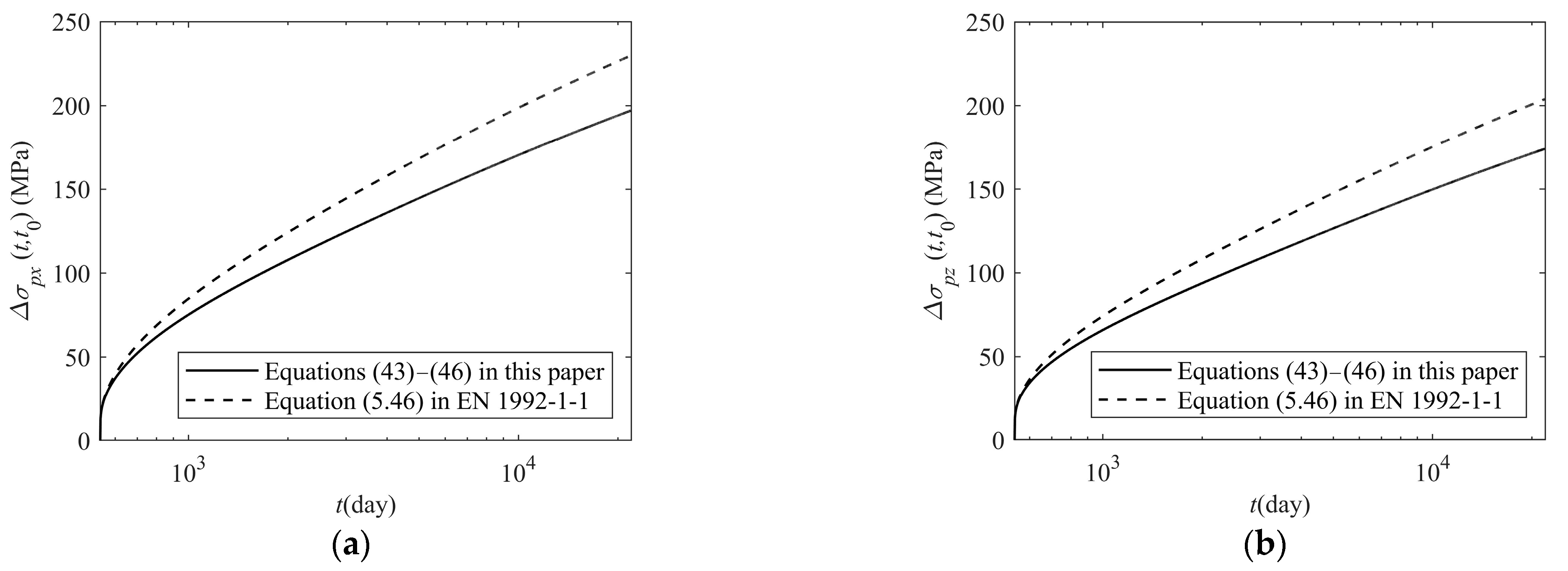
  • The advantage of the proposed method is the consideration of the interaction of two-way prestress, mild steel rebars, and the steel liner in two directions. In the case of neglecting the interaction of two-way prestress and the influence of mild steel rebars and the steel liner in two directions, the equations derived in this study reduce to the ones in the design code such as Eurocode 2, which means that the equation for the prestress loss estimation in the design code is the degeneration of the one in this study.
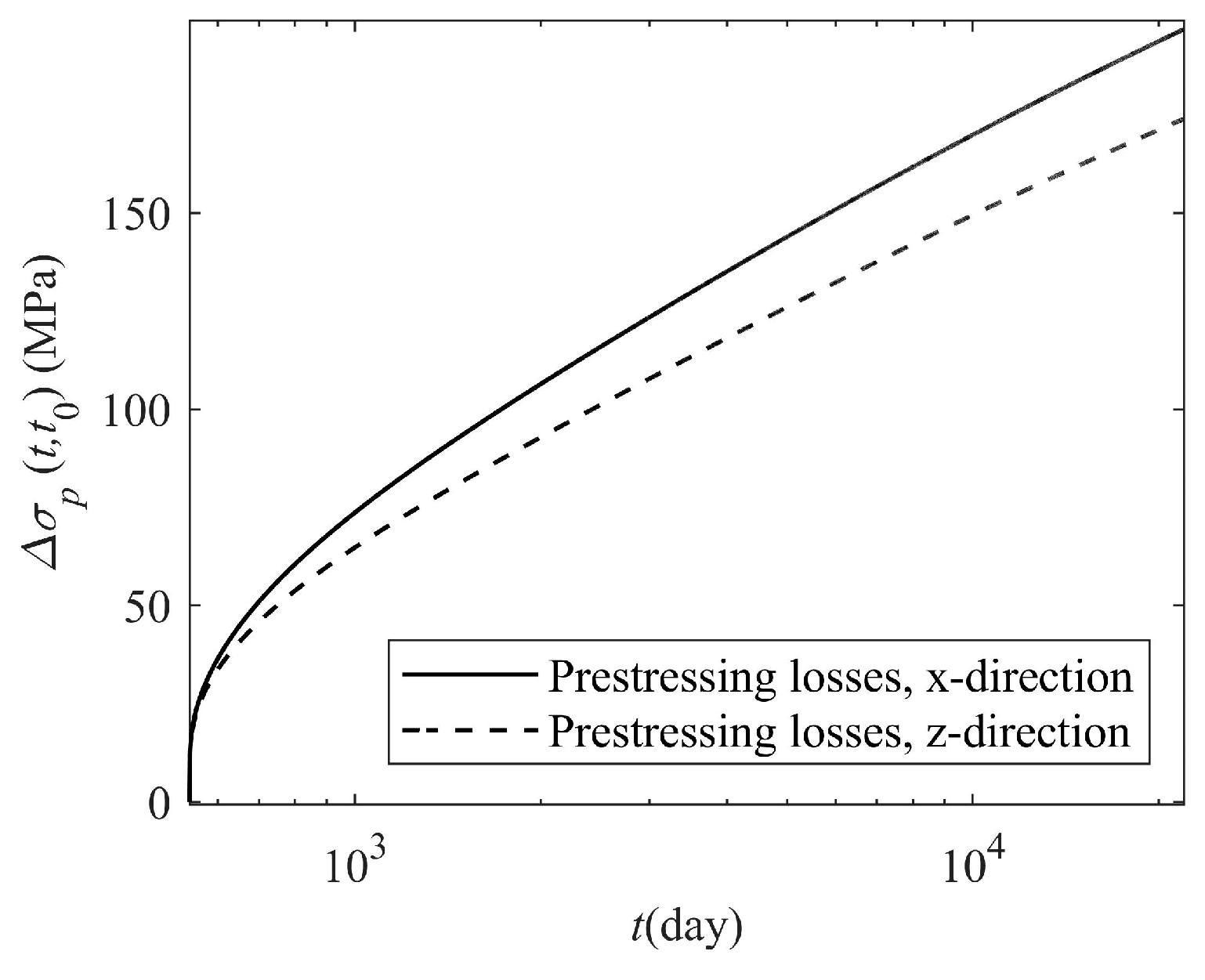
  • The consideration of the interaction of two-way prestress and the existence of mild steel rebars and the steel liner in two directions reduces the prestress loss of the prestressed concrete containment.

Author Contributions

Conceptualization, X.W. (Xingyi Wu); Methodology, X.W. (Xingyi Wu); Software, X.W. (Xingyi Wu); Validation, X.W. (Xingchao Wang); Formal Analysis, X.W. (Xingchao Wang); Investigation, X.L.; Resources, X.L.; Data Curation, X.W. (Xingyi Wu); Writing—Original Draft, X.W. (Xingyi Wu); Writing—Review and Editing, J.G.; Supervision, J.G.; Project Administration, J.G.; Funding Acquisition, J.G. All authors have read and agreed to the published version of the manuscript.

Funding

The research work is financially supported by the National Natural Science Foundation of China (Grant NO. U22B20125), which is greatly acknowledged.

Data Availability Statement

All data supporting the findings of this study are available from the corresponding author upon reasonable request, but all personally identifiable information will be identified before transferal.

Conflicts of Interest

The authors declare no conflict of interest.

Appendix A. Derivation of One-Way Prestress Loss Equation Based on the General Equations in this Study

Ignoring the existence of the steel liner and steel rebars in the containment and the interaction of prestress in two directions means taking ρ s x = 0 , ρ s x 1 = 0 , ρ s x 2 = 0 , ρ s z = 0 , ρ s z 1 = 0 , ρ s z 1 = 0 , μ c = 0 , and μ s = 0 , and the solutions to Equations (43) and (44) can be found as follows:
Δ ε c x ( t , t 0 ) = 1 + y p x h ρ p x r p x h E p E c ( t , t 0 ) φ ( t , t 0 ) E c t 0 σ c x ( t 0 , 0 ) 1 E c ( t , t 0 ) ρ p x r p x 0 χ r σ p r x ( t , t 0 ) + Δ ε s h ( t , t s , t 0 ) y p x h ρ p x r p x 0 E p E c ( t , t 0 ) φ ( t , t 0 ) E c t 0 σ c x ( t 0 , h ) 1 E c ( t , t 0 ) ρ p x r p x h χ r σ p r x ( t , t 0 ) + Δ ε s h ( t , t s , t 0 ) 1 + 1 y p x h ρ p x r p x 0 E p E c ( t , t 0 ) + y p x h ρ p x r p x h E p E c ( t , t 0 ) Δ ε c x ( t , t 0 ) = 1 y p x h ρ p x r p x h E p E c ( t , t 0 ) φ ( t , t 0 ) E c t 0 σ c x ( t 0 , 0 ) 1 E c ( t , t 0 ) ρ p x r p x 0 χ r σ p r x ( t , t 0 ) + Δ ε s h ( t , t s , t 0 ) + 1 + 1 y p x h ρ p x r p x 0 E p E c ( t , t 0 ) φ ( t , t 0 ) E c t 0 σ c x ( t 0 , h ) 1 E c ( t , t 0 ) ρ p x r p x h χ r σ p r x ( t , t 0 ) + Δ ε s h ( t , t s , t 0 ) 1 + 1 y p x h ρ p x r p x 0 E p E c ( t , t 0 ) + y p x h ρ p x r p x h E p E c ( t , t 0 )
The strain of concrete at the centroid of the prestressing strand in the x-direction can be obtained using Equations (24) and (25):
Δ ε p x ( t , t 0 ) = Δ ε c x ( t , t 0 ) + y p x h Δ ε c x ( t , t 0 ) Δ ε c x ( t , t 0 ) = φ ( t , t 0 ) E c t 0 σ c x ( t 0 , 0 ) + y p x h σ c x ( t 0 , h ) σ c x ( t 0 , 0 ) ρ p x χ r σ p r x ( t , t 0 ) E c ( t , t 0 ) 1 + A c x I c x e p x 2 + Δ ε s h ( t , t 0 ) 1 + ρ p x E p E c ( t , t 0 ) 1 + A c x I c x e p x 2 = φ ( t , t 0 ) E c t 0 σ c x ( t 0 , y p x ) ρ p x χ r σ p r x ( t , t 0 ) E c ( t , t 0 ) 1 + A c x I c x e p x 2 + Δ ε s h ( t , t s , t 0 ) 1 + ρ p x E p E c ( t , t 0 ) 1 + A c x I c x e p x 2
Substituting Equation (A2) into Equation (17) yields the following equation for evaluation of prestress loss of the prestressing strand in the x-direction:
Δ σ p x t , t 0 = E p Δ ε p x ( t , t 0 ) + χ r σ p r x ( t , t 0 ) = Δ ε s h ( t , t 0 ) E p + χ r σ p r x ( t , t 0 ) + E p E c t 0 φ ( t , t 0 ) σ c x ( t 0 , y p x ) 1 + E p E c t 0 A p x A c 1 + A c x I c x e p x 2 1 + χ φ t , t 0
Taking the same approach obtains the equation for evaluation of prestress loss of the prestressing strand in the z-direction:
Δ σ p z t , t 0 = Δ ε s h ( t , t 0 ) E p + χ r σ p r z ( t , t 0 ) + E p E c t 0 φ ( t , t 0 ) σ c z ( t 0 , y p z ) 1 + E p E c t 0 A p z A c 1 + A c z I c z e p z 2 1 + χ φ t , t 0
Both Equations (A3) and (A4) are the same as the expressions in Eurocode EN 1992-1-1:2004 for prediction of prestress loss of the prestressed concrete member.

References

  1. Li, X.; Gong, J. Effects of steel liner corrosion on the leak-tightness of prestressed concrete containment structure under severe accident loads. Ann. Nucl. Energy 2023, 180, 109487. [Google Scholar] [CrossRef]
  2. Guo, T.; Chen, Z.; Lu, S.; Yao, R. Monitoring and analysis of long-term prestress losses in post-tensioned concrete beams. Measurement 2018, 122, 573–581. [Google Scholar] [CrossRef]
  3. Yang, Y.; Tang, H.; Mao, Y.; Wang, X. Prediction of Long-Term Prestress Loss and Crack Resistance Analysis of Corroded Prestressed Concrete Box-Girder Bridges. Adv. Civ. Eng. 2022, 2022, 1309936. [Google Scholar] [CrossRef]
  4. Breccolotti, M. On the evaluation of prestress loss in PRC beams by means of dynamic techniques. Int. J. Concr. Struct. Mater. 2018, 12, 1. [Google Scholar] [CrossRef]
  5. Bonopera, M.; Chang, K.C. Novel method for identifying residual prestress force in simply supported concrete girder-bridges. Adv. Struct. Eng. 2021, 24, 3238–3251. [Google Scholar] [CrossRef]
  6. Song, H.W.; Kim, S.H.; Byun, K.J.; Song, Y.C. Creep prediction of concrete for reactor containment structures. Nucl. Eng. Des. 2002, 217, 225–236. [Google Scholar] [CrossRef]
  7. Bažant, Z.P.; Panula, L. Practical prediction of time-dependent deformation of concrete, part III and IV. Mater. Struct. 1978, 11, 415–434. [Google Scholar]
  8. Cai, D.; Wang, Y.; Zhang, J.; Yang, L.; Rong, H.; Li, J.; Wu, Z. Prestressed time-limited aging analyses of concrete containment structure. In Proceedings of the 2017 25th International Conference on Nuclear Engineering ICONE25, Shanghai, China, 2–6 July 2017. [Google Scholar]
  9. Lundqvist, P.; Nilsson, L.O. Evaluation of prestress losses in nuclear reactor containments. Nucl. Eng. Des. 2011, 241, 168–176. [Google Scholar] [CrossRef]
  10. Bílý, P.; Kohoutková, A.; Holan, J. Time-dependent strains of prestressed concrete containment vessels: Validation of analytical model by real-world data. Eng. Struct. 2022, 262, 114403. [Google Scholar] [CrossRef]
  11. Anderson, P. Thirty years of measured prestress at Swedish nuclear reactor containments. Nucl. Eng. Des. 2005, 235, 2323–2336. [Google Scholar] [CrossRef]
  12. Yang, Q.; Yao, D.; Yan, J.; Liu, M.; Fan, F.; Fu, Z. Analysis of time-varying mechanical properties of prestressed concrete containment during the tensioning process and service considering the influence of creep. Int. J. Press. Vessel. Pip. 2023, 204, 104962. [Google Scholar] [CrossRef]
  13. Zhang, H.; Guo, Q.Q.; Xu, L.Y. Prediction of long-term prestress loss for prestressed concrete cylinder structures using machine learning. Eng. Struct. 2023, 279, 115577. [Google Scholar] [CrossRef]
  14. Hu, H.T.; Lin, J.X. Ultimate analysis of PWR prestressed concrete containment under long-term prestressing loss. Ann. Nucl. Energy 2016, 87, 500–510. [Google Scholar] [CrossRef]
  15. Kjolsing, E.; James, R.; Kubischta, K.; Dan, P. Assessing prestress losses in a nuclear containment structure for license renewal. In Proceedings of the ASME 2019 Power Conference POWER2019, Salt Lake City, UT, USA, 15–18 July 2019. [Google Scholar]
  16. Ramaswamy, A. Uncertainty based model averaging for prediction of long-time prestress losses in concrete structures. Constr. Build. Mater. 2017, 153, 469–480. [Google Scholar]
  17. Berveiller, M.; Pape, Y.L.; Sudret, B.; Perrin, F. Updating the long-term creep strains in concrete containment vessels by using Markov chain Monte Carlo simulation and polynomial chaos expansions. Struct. Infrastruct. Eng. 2012, 8, 425–440. [Google Scholar] [CrossRef]
  18. Balomenos, G.P.; Pandey, M.D. Probabilistic finite element investigation of prestressing loss in nuclear containment wall segments. Nucl. Eng. Des. 2017, 311, 50–59. [Google Scholar] [CrossRef]
  19. AFCEN. RCC-CW 2015; Rules for Design and Construction of PWR Nuclear Civil Works. French Association for Design, Construction and In-Service Inspection Rules for Nuclear Island Components: Paris, France, 2015.
  20. ACI 359-13; Rules for Construction Nuclear Facility Components III, Code for Concrete Containments Division 2. The American Society of Mechanical Engineering: New York, NY, USA, 2013.
  21. Wang, W.; Gong, J.; Wu, X.; Wang, X. A general equation for estimation of time-dependent prestress losses in prestressed concrete members. Structures 2023, 55, 278–293. [Google Scholar] [CrossRef]
  22. Li, X.; Gong, J. Probabilistic evaluation of the leak-tightness function of the nuclear containment structure subjected to internal pressure. Reliab. Eng. Syst. Saf. 2024, 241, 109684. [Google Scholar] [CrossRef]
  23. Evans, R.H.; Wood, R.H. Transverse elasticity of building materials. Engineering 1937, 143, 161–163. [Google Scholar]
  24. Kordina, K. Experiments on the influence of the mineralogical character of aggregates on the creep of concrete. RILEM Bull. 1960, 6, 7–22. [Google Scholar]
  25. Gvozdev, A.A. Creep of concrete. Mekhanika Tverd. Tela 1966, 137–152. [Google Scholar]
  26. Charpin, L.; Pape, Y.L.; Coustabeau, É.; Toppani, É.; Heinfling, G.; Bellego, C.L.; Masson, B.; Montalvo, J.; Courtois, A.; Sanahuja, J. A 12year EDF study of concrete creep under uniaxial and biaxial loading. Cem. Concr. Res. 2018, 103, 140–159. [Google Scholar] [CrossRef]
  27. Pprrott, L.J. Lateral strains in hardened cement paste under short- and long-term loading. Mag. Concr. Res. 1974, 26, 198–202. [Google Scholar] [CrossRef]
  28. Jordaan, I.J.; Illston, J.M. Time-dependent strains in sealed concrete under systems of variable multiaxial stress. Mag. Concr. Res. 1971, 23, 79–88. [Google Scholar] [CrossRef]
  29. Gopalakrishnan, K.S.; Neville, A.M.; Ghali, A. Creep Poisson’s ratio of concrete under multiaxial compression. J. Proc. 1969, 66, 1008–1019. [Google Scholar]
  30. Meyer, H.G. On the influence of water content and of drying conditions on lateral creep of plain concrete. Matériaux Et Constr. 1969, 2, 125–131. [Google Scholar] [CrossRef]
  31. Bažant, Z.P.; Jirásek, M. Creep and Hygrothermal Effects in Concrete Structures. In Solid Mechanics and its Applications; Springer: Berlin/Heidelberg, Germany, 2018. [Google Scholar]
  32. Yang, M. Refined Calculation of Long-Term Deformation of Simply Supported Post-Tensioned Prestressed Concrete Bridges. Ph.D. Thesis, Dalian University of Technology, Dalian, China, 2021. [Google Scholar]
  33. fib Model Code. fib Model Code for Concrete Structures; Thomas Telford Ltd.: London, UK, 2010; p. 2013. [Google Scholar]
  34. Bílý, P.; Kohoutková, A. A numerical analysis of the stress-strain behavior of anchorage elements and steel liner of a prestressed concrete containment wall. Structures 2017, 12, 24–39. [Google Scholar] [CrossRef]
  35. EN 1992-1-1:2004; Eurocode 2: Design of Concrete Structures–Part 1–1. General Rules and Rules for Buildings. European Commission: Brussels, Belgium, 2004.
  36. Furr, H.L. Creep Tests of Two-Way Prestressed Concrete. ACI J. 1967, 64, 288–294. [Google Scholar]
  37. ACI 209.2R-08; Guide for Modeling and Calculating Shrinkage and Creep in Hardened Concrete. American Concrete Institute (ACI): Farmington Hills, MI, USA, 2008.
Figure 1. Steel liner, steel rebars, and prestressing strands in section of prestressed concrete containment.
Buildings 13 02513 g001
Figure 2. Prestressed concrete containment element in the regular segment: (a) total force of the element; (b) areas of steel liner, steel rebars, and prestressing tendons; (c) forces of steel liner, steel rebars, and prestressing tendons.
Buildings 13 02513 g002
Figure 3. Strain distribution of concrete along the thickness of section of containment in x-direction and z-direction.
Buildings 13 02513 g003
Figure 4. Comparison of predicted [33,35,37] and measured creep of prestressed slabs: (a) 6.89 MPa (1000 psi) two-way prestressed slab; (b) 13.79 MPa (2000 psi) two–way prestressed slab; and (c) 20.68 MPa (3000 psi) two-way prestressed slab.
Buildings 13 02513 g004
Figure 5. Comparisons of predicted [33,35,37] and measured time-dependent two-way prestress losses of prestressed slabs: (a) percentages of the prestress loss to the initial prestress and to 313-day prestress loss in 13.79 MPa (2000 psi) two-way prestressed slab, and (b) percentages of the prestress loss to the initial prestress and to 313-day prestress loss in 20.68 MPa (3000 psi) two-way prestressed slab.
Buildings 13 02513 g005aBuildings 13 02513 g005b
Figure 6. Section of the regular segment of the prestressed concrete containment and the configuration of the reinforcement (dimension unit: mm): (a) x-section and (b) z-section.
Buildings 13 02513 g006
Figure 7. Prestressing losses in x-direction and z-direction.
Buildings 13 02513 g007
Figure 8. The total stresses in the concrete at the innermost and outermost fiber of the containment (take the compression as positive): (a) innermost fiber in x-direction; (b) outermost fiber in x-direction; (c) innermost fiber in z-direction; and (d) outermost fiber in z-direction.
Buildings 13 02513 g008
Figure 9. The total stresses in the steel liner and in the centroid of steel rebars in x-direction and z-direction (take the compression as positive): (a) steel liner and centroid of steel rebars in x-direction and (b) steel liner and centroid of steel rebars in z-direction.
Buildings 13 02513 g009
Figure 10. Comparison of the calculation methods of this paper with that of EN 1992-1-1:2004 [35]: (a) prestressing losses in x-direction and (b) prestressing losses in z-direction.
Buildings 13 02513 g010
Figure 11. Prestressing losses in x-direction and z-direction at different transfer times: (a) prestressing losses in x-direction and (b) prestressing losses in z-direction.
Buildings 13 02513 g011
Table 1. Properties of the test specimens in Ref. [36].
DesignationTypeSize (mm × mm × mm)Initial Stress f c
C-1Ptwo-way prestress610 × 610 × 646.89 MPa, two-way33.1649 MPa
C-2Ptwo-way prestress610 × 610 × 6413.79 MPa, two-way31.5791 MPa
C-3Ptwo-way prestress610 × 610 × 6420.68 MPa, two-way35.0266 MPa
S-1PC-1P control610 × 610 × 64 None33.1649 MPa
S-2PC-2P control610 × 610 × 64None31.5791 MPa
S-3PC-3P control610 × 610 × 64None35.0266 MPa
Table 2. Geometric properties of the section of the regular segment element in the prestressed concrete containment.
DirectionArea of Section Concrete (mm2) Distance from Innermost Fiber to Centroid (mm) Moment of Inertia (mm4)
x A c x 1,980,000 y c x 600 I c x 2.3760 × 10¹¹
z A c z 540,000 y c z 600 I c z 6.4800 × 10¹⁰
Table 3. Steel liner, steel rebars, and prestressing tendons in the regular segment element of the prestressed concrete containment.
MemberArea (mm2) Reinforcement Ratio (%) Distance (mm) Eccentricity (mm) Geometric   Parameter   r   ( y = 0 ) Geometric   Parameter   r   ( y = h )
Steel liner, x-direction A s x 9900 ρ s x 0.50 y s x 0 e s x −600 r s x 0 4.00 r s x h −2.00
Steel liner, z-direction A s z 2700 ρ s z 0.50 y s z 0 e s z −600 r s z 0 4.00 r s z h −2.00
Inner steel rebars, x-direction A s x 1 11,259 ρ s x 1 0.57 y s x 1 226 e s x 1 −374 r s x 1 0 2.87 r s x 1 h −0.87
Outer steel rebars, x-direction A s x 2 11,259 ρ s x 2 0.57 y s x 2 1099 e s x 2 499 r s x 2 0 −1.495 r s x 2 h 3.495
Inner steel rebars, x-direction A s z 1 3770 ρ s z 1 0.70 y s z 1 190 e s z 1 −410 r s z 1 0 3.05 r s z 1 h −1.05
Outer steel rebars, z-direction A s z 2 3770 ρ s z 2 0.70 y s z 2 1063 e s z 2 463 r s z 2 0 −1.315 r s z 2 h 3.315
Prestressing tendons, x-direction A p x 24,300 ρ p x 1.23 y p x 900 e p x 300 r p x 0 −0.50 r p x h 2.50
Prestressing tendons, z-direction A p z 8100 ρ p z 1.50 y p z 600 e p z 0 r p z 0 1 r p z h 1
Disclaimer/Publisher’s Note: The statements, opinions and data contained in all publications are solely those of the individual author(s) and contributor(s) and not of MDPI and/or the editor(s). MDPI and/or the editor(s) disclaim responsibility for any injury to people or property resulting from any ideas, methods, instructions or products referred to in the content.

