Article

Comparative Review of the Technology and Case Studies of 3D Concrete Printing of Buildings by Several Companies

1
Civil Engineering Master of Science, The Pennsylvania State University, University Park, PA 16802, USA
2
Architectural Engineering and Civil and Environmental Engineering Departments, The Pennsylvania State University, University Park, PA 16802, USA
*
Author to whom correspondence should be addressed.
Buildings 2023, 13(1), 106; https://doi.org/10.3390/buildings13010106
Submission received: 2 November 2022 / Revised: 9 December 2022 / Accepted: 23 December 2022 / Published: 31 December 2022
(This article belongs to the Special Issue Advances in Additive Manufacturing and Construction 4.0)

Abstract

:
This paper dives into the current state of 3D printing in the concrete industry. Currently, there are a number of companies that specialize in the construction of buildings using 3D-printed concrete. This paper looks at each of these companies and the processes they use to accomplish the creation of their concrete walls using 3D-printing technology. The literature review portion of the paper looks at several companies currently in the field and describes their methods based on several distinguishing factors such as printer type, print speed, wall design, reinforcement used, insulation used, wall dimensions, nozzle shape, and several other distinguishing factors. These factors allow for similarities and differences to be drawn between companies. The reader is able to see each company’s approach to the printing of walls. Additionally, this paper estimates and analyzes the structural and thermal performance of drawings mimicking each company’s wall design based on section configuration. This estimation allows the reader to see which wall design they can expect to perform the best in terms of stress generation and thermal bridging.

1. Introduction

1.1. Introduction and Background to the Industry

In the present day, the housing market struggles as construction prices skyrocket, the labor force dwindles, and housing demand drastically outweighs supply [1]. For years, researchers in the construction industry have been developing methods to solve many of the industry’s problems. One possible solution is the use of additive manufacturing to create a structure’s walls. According to Elfatah [2], companies use 3D printers, stacking concrete layers on top of each other to form a hollow wall, and then the cavities are filled with insulation, cast concrete, and likely receive steel reinforcement. Thus, a building’s walls can be completely printed from a 3D printer [2]. The designer can program their wall design into this printer’s software (using Computer Aided Design software) and the printer will continually stack concrete layers on top of each other to match the design uploaded by the designer [2]. After the concrete in the wall is set, mechanical systems, electrical systems, windows, and doors are placed in the structure. This process is especially important for building construction, but it can also be used in other forms of construction such as bridges and structures (such as buildings) on other planets (if needed in the future) [2]. However, with this being such a new technology, companies accomplish the stacking of concrete in a variety of ways.
As technology advances, 3D printing of concrete has the ability to impact the global construction industry [2]. This technology has the potential of reducing overall construction costs (possibly providing more affordable housing) [2]. With this being said, the industry today still faces challenges that need to be addressed. More specifically, each company in the field uses a different printed wall configuration to accomplish maximum structural and thermal efficiency. Additionally, companies utilize different printing techniques to maximize print efficiency and quality. For example, some companies use a gantry style printer (with a print head that slides on a metal frame), whereas other companies use a robotic arm style printer (with a print head on a main body that rotates and moves on wheels). For this reason, the primary objective of this study is to identify and analyze a selected number of 3D-printing construction companies’ printing methods and designs in order to provide a comparative perspective of their printing systems and their signature wall design configurations.
This paper highlights the ways several different concrete-printing companies accomplish the stacking of extruded concrete and the shaping of the cross-sectional shape of the walls, which will affect thermal performance and load resistance behavior. Many companies have made strides in the 3D-printed concrete field. In this review, many of the companies at the forefront of the technology are discussed. First, ICON, a company from Austin, Texas that prints homes in the United States and Mexico [3], is discussed. Next, Black Buffalo, a relatively new company from the United States that helps build structures with the printers they build, [4] is investigated. Next, Another American company, Apis Cor, that creates machines and then prints homes with them is discussed [5,6]. Apis Cor has completed projects in several countries, including Russia and Dubai [5,6]. Another American company SQ4D is discussed, which has also made significant strides in creating wall systems with their own printers [7,8]. After SQ4D, COBOD, a company from Denmark, which creates printers for the use of a company-named PERI, is discussed [9]. This is followed by CyBe, a company from the Netherlands that creates printers as well. Next WASP (acronym stands for World’s Advancing Saving Project), an Italian company that was founded in 2012, is discussed [10]. Two companies from China are also introduced: WinSun that was founded in 2014 [11] and Huashang Tengda that has completed several projects throughout the country of China [12].
Though several universities have made significant contributions to the field (e.g., University of Southern California, Penn State University, Iowa State University, ETH Zurich University, Eindhoven University of Technology, and Tsinghua University), this paper is specifically focused on the state of the practice by the more established companies using this technology. Therefore, great contributions by the universities toward research accomplishments in the field are acknowledged by the author of this paper, who is a Master of Science in Civil Engineering student at the Pennsylvania State University. The work done or ongoing at these universities is be reviewed in this paper in order to keep the focus on what is currently being practiced. In this review, the printer machine, strength development method, and insulation method are analyzed for each company’s technology that is presented. Additionally, the printer and printing method distinction use criteria from Elfatah to help properly distinguish between different processes amongst companies [2]. These criteria include printer layer type (layer by layer versus powder bed), printer movement type (robotic versus gantry style printer), printer location (on site versus prefabrication), and printed wall type (load bearing versus hollow form work).
In all, this paper focuses on the state of the art of companies that currently use this 3D concrete printing technology. Due to its recent development, this is a unique topic that has not been thoroughly studied elsewhere. As a result, there are certain limitations in finding information that companies were not willing to release due to the information being proprietary to each company.

1.2. Literature Review of Issues and Future Endeavors of the Industry

As previously mentioned, the construction industry is prone to slow productivity and poor overall performance [13]. As a result, researchers are currently exploring ways to improve these shortcomings of the construction industry. More specifically, Keivani et al. mention “industrial production”, “cyber-physical systems”, and “digital and computational technologies” as possible solutions to this problem [13]. Industrial production includes the use of prefabrication and offsite manufacturing in the construction process [13]. Additionally, cyber-physical systems include the use of robots and drones to improve the overall performance within the construction industry. Finally, digital and computational technologies include the use of Building Information Modeling (BIM) and Artificial Intelligence to address these shortcomings within the construction industry [13].
All three of these areas directly apply to 3D printing concrete. To elaborate, the use of robots (as mentioned in cyber-physical systems) is the main focus of 3D printing concrete. For example, 3D printing concrete uses different types of robotic systems (such as gantry systems) to stack concrete layers, eventually rising to form a wall [14]. Additionally, Tay et al. discuss the possible use of BIM in the 3D concrete printing industry. For example, the use of BIM in 3D concrete printing would improve efficiency as all required software packages would be available in only one software [14]. As a result, design changes would be streamlined [14]. Not only would the design of the structure be in just one file, but a resulting model of the revised structure would also be visible to the contractor and designer [14]. For these reasons, these topics covered by Keivani et al. have increased in popularity in recent years [13]. The increase in popularity and research conducted are a clear indication of the need for improved construction efficiency and why 3D printing concrete is a solution that should be explored further [13].
With the increased research performed into topics such as 3D printing concrete, the 3D printing concrete industry has made large developments within the last 10 years [15]. Buswell et al. state that 3D concrete printing creates structures by “precisely placing, or solidifying, specific volumes of material in sequential layers by a computer-controlled positioning process” [15]. As a result, most of the 3D concrete printing methods involve the extrusion of concrete beads [15].
However, with this new technology, there are still certain questions that must be addressed within the industry [15]. Currently, the process of 3D concrete printing is specialized [15]. Thus, an experienced machine operator that understands the software and hardware of the printer must be present to fix any issues that may arise [15]. Additionally, there are other issues currently present in 3D concrete printing that limits its ability to become fully mainstream at the moment [15]. One of these issues includes the pumpability of the concrete used [15]. Currently, users of 3D concrete printing struggle with the desired pumpability of their concrete [15]. For example, if the concrete has a low viscosity, it will not hold its desired shape after it has been extruded from the printer head [15]. On the other hand, if the concrete has a high viscosity, it will clog the pump, leading to no concrete being printed [15]. Additionally, at the time of writing this paper, there is no method to test and quantify the required pumpability of the concrete being printed (each machine requires different amount of pumpability) [15]. Instead, users are forced to perform a visual evaluation for their concrete’s pumpability [15]. There are also issues involving the speed at which concrete can be printed [15]. Obviously, it would be beneficial to print structures as quickly as possible. More specifically, a faster print results in a reduction in cold joints formed between concrete layers (due to newly extruded concrete coming into contact with older concrete) [15]. However, printers cannot print as fast as desired due to the constant changing of direction of the nozzle that is required to form the desired wall shape [15]. There are also questions around the cold joints that form due to newly printed concrete extruded on top of older concrete [15]. In more detail, there is little information about the effect of these cold joints [15]. At the moment, it remains unclear whether these cold joints play an effect in the overall performance of the wall [15]. For this reason, it could be seen as a risk for governments to allow these types of homes without understanding how these factors affect the performance of these structures.
Additionally, there are several techniques used to 3D print objects of all sizes [14]. The first technique is binder jetting [14]. In this process, a structure is created by releasing a binder (drop by drop) on top of a powder bed [14]. As a result of the binder reacting with the powder bed, pieces of the structure are connected together [14]. This method is then repeated until the desire shape is formed [14]. Once formed, the remaining material that has not reacted with the binder provides support to the printed structure [14]. Following the formation of the structure, the unreacted material is removed, and the desired structure remains [14]. Though an intriguing printing method, this process has not been popularized for a number of reasons [14]. One being the detrimental effect that weather can have on the printing process [14]. The next printing method utilized is the material deposition method [14]. In this process, material is laid down layer by layer from a nozzle [14]. The path of the nozzle is determined by the project’s CAD model, and the subsequent layer are laid on top of each other until the desired structure has been formed [14]. A form of the material deposition method is contour crafting [14]. In contour crafting, a gantry-style printer lays down concrete in a layer-by-layer method [14]. The process and use of a gantry-style printer will be explored and expanded upon later in the paper [14].

2. Materials and Methods

2.1. Capabilities and Attributes of Gantry System Printers Used by Different Companies

2.1.1. ICON

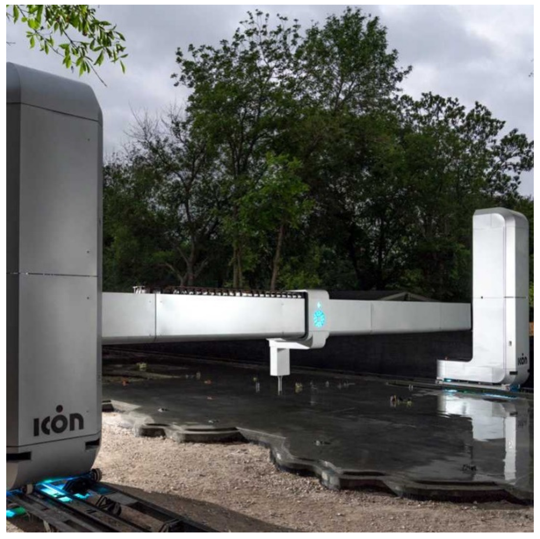
One of the first companies in the 3D concrete printing field, ICON prints homes predominately in Mexico and the United States of America [3]. To properly print the walls for building homes, ICON uses a gantry system printer, which allows the printer head to slide on metal framework in all three axes [16]. This gantry process allows the print head to orient itself perfectly vertical (without any tilt), which helps improve print quality [17]. The ICON printer can print objects up to 3.2 m (10.5 ft) tall and 11.125 m (36.5 ft) wide in place at the construction site [18]. Additionally, their gantry system has no restriction on the length of objects printed since it is positioned on wheels [18]. This means that the length of track placed on site will control the total printable length of the wall. This is a huge advantage for ICON and their gantry printer as many other companies face print dimension restrictions.
ICON’s printer, which can be seen in Figure 1, is able to extrude concrete bead (filament), printing layers of concrete on top of each other. [18]. To accomplish this, the company uses its own proprietary mortar mix–Lavacrete. ICON states that their mix produces a mortar with a compressive strength of 13.8–24.13 MPa (2000 to 3500 psi) [18]. The process of printing a concrete bead layer and then the printer placing another concrete bead layer on top of the previous layer to create a wall of desired height is known as the layer-by-layer technique [2].
Additionally, ICON designs and prints all of their printed walls to act as “stay-in-place” formwork [16]. This means that the walls ICON prints are hollow, i.e., it prints the shell. However, ICON uses a special wall design, which is different compared to wall details of other companies in that it prints a wall that contains three cavity spaces. Following the printing of these shells/webs, the cavities are then filled with insulation for thermal performance as well as concrete and rebar for structural performance [20]. Typically, ICON uses a spray foam in the insulation cavity [21]. For reinforcement, ICON places vertical steel reinforcement in the concrete cavity [20]. Then, it appears concrete (cast-in-place) is poured into the cavity with the rebar [20]. A drawing mimicking ICON’s wall design can be seen in Figure 2, which includes concrete connecting the exterior to interior to remain consistent with other walls drawn in the Appendix A for the study in this paper.
ICON has completed several projects where these techniques have been put to practice. For example, one of ICON’s first projects was the Chicon house, which received the first permit for a three-dimensional (3D) printed house in the United States [5]. To print this house, ICON used the predecessor to their current printer, the Vulcan. In total, according to Zainab [5], the walls of the house (about 55.74–74.32 square m (600–800 square ft)) were printed in approximately 24 h. The total cost of the printed house was approximately $10,000, and the house itself can be seen in Figure 3 [16].

2.1.2. COBOD

Another company that has made great progress in the automated construction field is COBOD (in collaboration with the PERI Group). COBOD (a company from Denmark) has printed homes predominantly in Europe [9]. Unlike ICON, COBOD only creates and sells the printers to automated construction companies (like the PERI Group) to print with [23]. However, like ICON, COBOD’s printers (most recently the BOD 2) use a gantry system [24]. Again, this means that the printer’s head sits on a metal framework, which then allows it to move in all three axes directions [24]. According to COBOD, the BOD 2 printer can print walls 14.5 m (47.5 ft) wide and 8.1 m (26.5 ft) tall [24]. Similar to the ICON printer, the BOD 2 has no limit in the length of a wall it can print, as more steel framing can be attached to the gantry system to increase printing length as needed [24].
The BOD 2 printer is able to print at a maximum rate of 1000 mm per second (39 in. per second) [24]. Additionally, COBOD places a material hopper above the print head to improve the consistency of flow through the printer’s nozzle [24]. The layers extruded from the BOD 2 printer are anywhere from 30 to 300 mm (1.2–11.8 in.) wide and anywhere from 5 to 30 mm (0.2–1.2 in.) tall (depending on mortar consistency) [24]. COBOD also produces its own mortar for the BOD 2 printer, which among other ingredients consists of (Table 1) 32% cement, 18% 0–2-mm (0–0.079 in.) (dia.) sand, 18% 0–4-mm (0–0.16 in.) (dia.) gravel, 23% 0–4-mm (0–0.16 in.) (maximum dimension) recycled roof tiles, and 9% water [24]. When cured, according to COBOD, this mortar has a compressive strength of about 44.8 MPa (6500 psi) [24].
The walls printed by COBOD’s printer are used as formwork for fill material [25]. PERI’s printed hollow walls can be filled with or without vertical reinforcement (among other things, it depends on the building’s environment, use, and local codes) [24,25]. For their walls with three cavities, concrete is filled into the interior cavity [24,25]. Then, the exterior cavity of this wall is filled with insulation to improve the wall’s thermal performance [25,26]. A COBOD printer was used by the PERI Group in Germany to create a wall with staples acting as horizontal reinforcement in the wall [25]. This can be seen clearly in Figure 4, which is a SolidWorks model mimicking COBOD’s wall design, which was modeled by the authors of this paper. This model is based on the information provided by Jarett Gross.
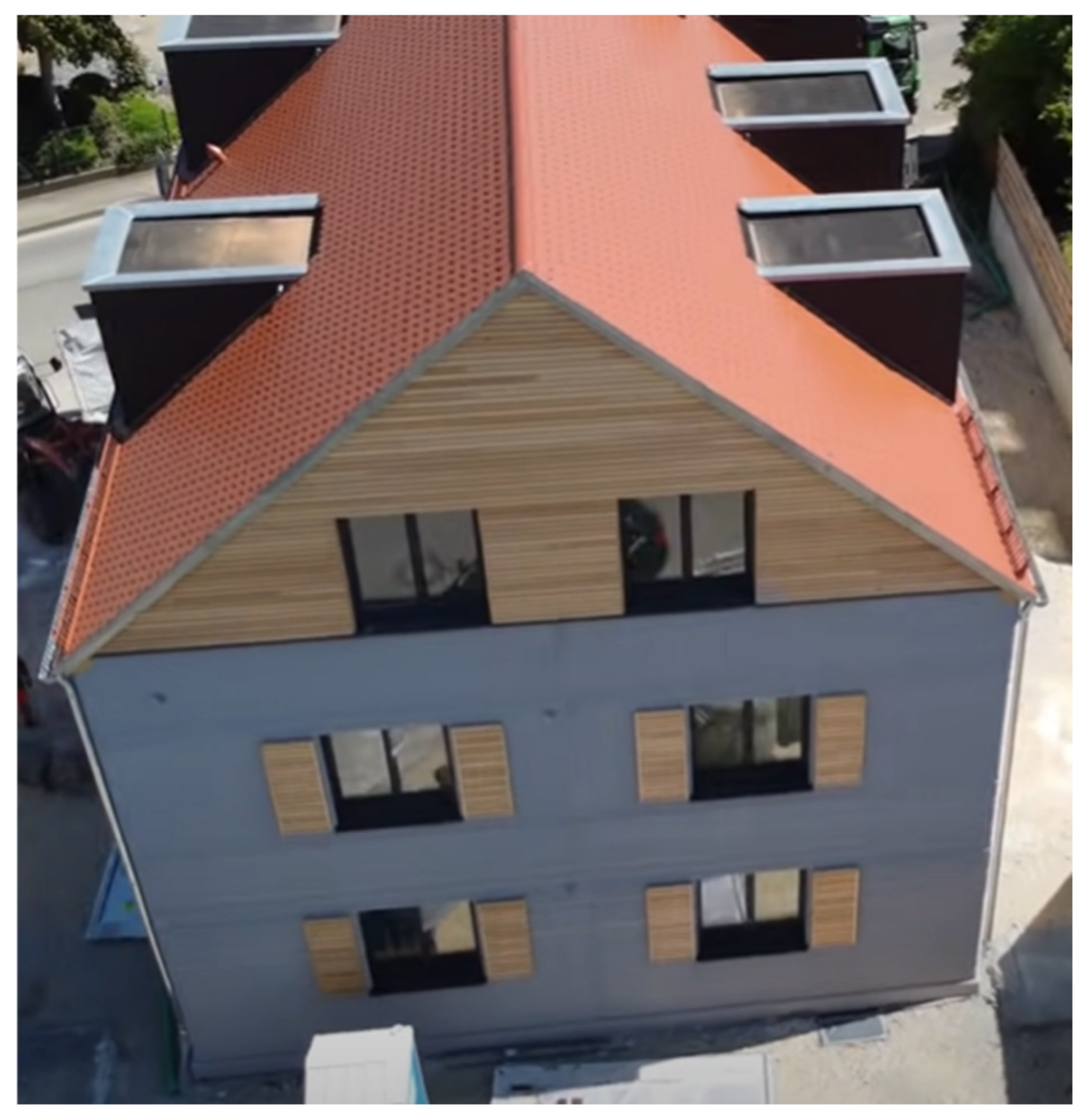
As stated before, COBOD manufactures 3D printers. They do not print buildings themselves. However, the PERI Group used a COBOD printer to construct an apartment building in Wallhausen Germany [27]. The walls for this structure did not include vertical reinforcement. Instead, concrete alone was poured into the wall cavity and considered as structural reinforcement [27]. For the walls in this building, the PERI Group also used expansion joints [27]. With the help of the BOD 2 printer, the PERI Group was able to complete the walls in this multistory structure in 7 days, which can be seen in Figure 5 [27].

2.1.3. Black Buffalo

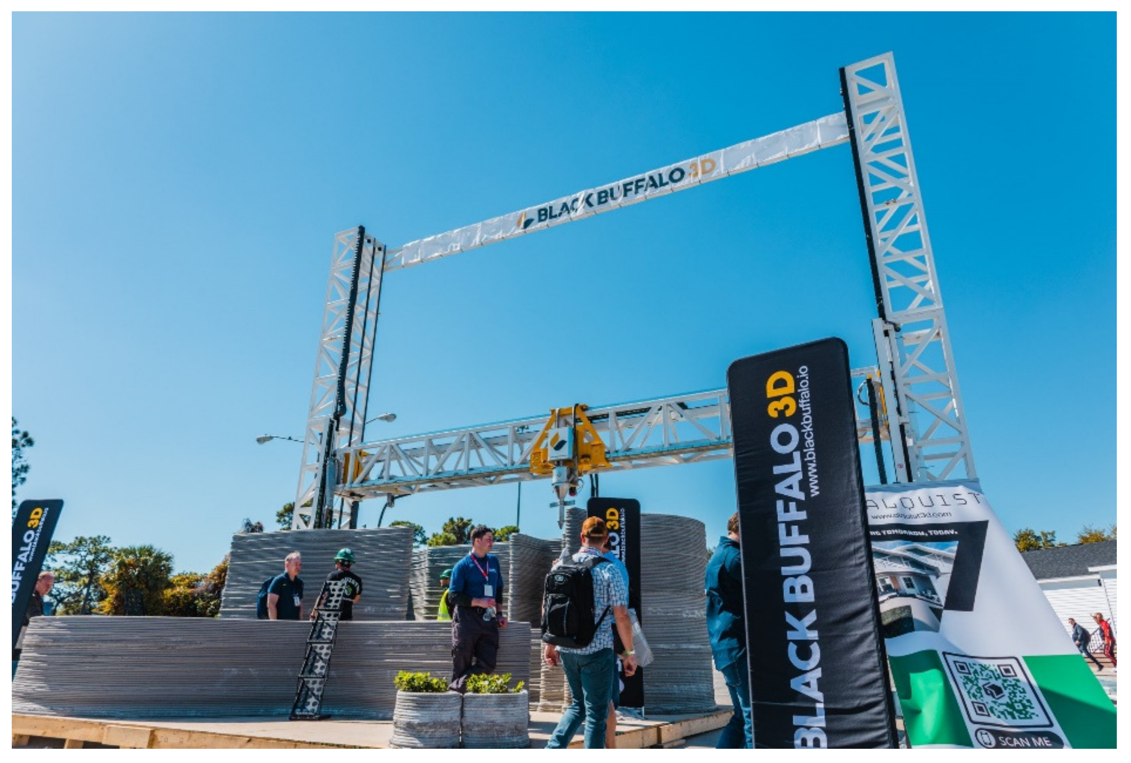
Another company to make progress in the printing of buildings is Black Buffalo. As seen before, Black Buffalo uses a gantry system to maneuver their printer, which is visible in Figure 6 [4]. Though Black Buffalo has not released specific dimensions for their printer’s print area, it is known that the printer can print up to a maximum print area of about 8 m by 8 m (315 in. by 315 in.) [4]. In addition to this, Black Buffalo’s printer is capable of printing walls that are up to three stories tall, which is unique in the industry [4]. As seen with other companies, tracks can be added onto the printer to extend the print area [4].
Additionally, Black Buffalo created their own mortar mix, which they call “3D Printer Ink” [4]. Though the printer is able to print at a faster rate, Black Buffalo follows the Occupational Safety and Health Administration’s standard of 249 mm per second (9.8 in. per second) [4]. It should also be noted that according to Peter Cooperman the head of marketing and strategy at Black Buffalo, Black Buffalo is “the first and only company to meet International Building Code Standards by testing for the ICC-ES AC509 at material, machine and structural wall levels.” The nozzle on the Black Buffalo printer contains several unique features. First, Black Buffalo has placed several cameras pointed at the nozzle of the printer [4]. This allows workers to easily perform quality assurance on the mortar leaving the nozzle. Black Buffalo also uses several different nozzle attachments, which allows workers to pick the best nozzle for each job [4]. Finally, like COBOD, there is a hopper placed above the nozzle head to ensure proper flow out of the nozzle [4].
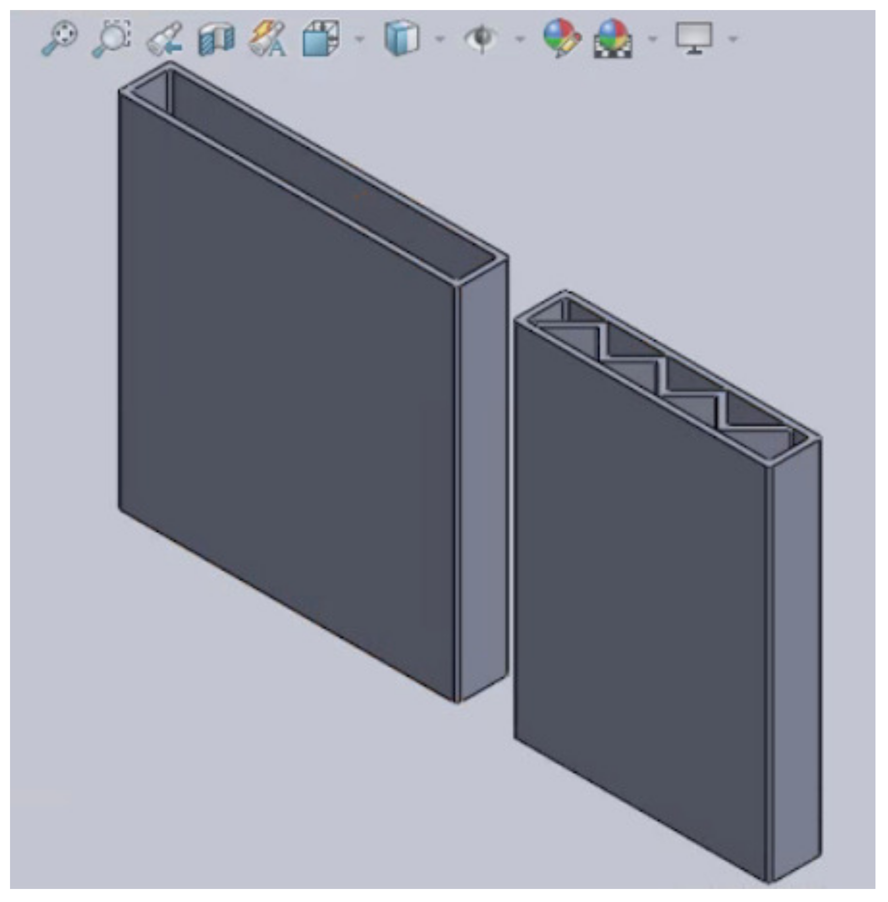
To ensure structural and thermal performance of their walls, Black Buffalo prints hollow walls, which can then filled with insulation, concrete, and reinforcement [28]. As these walls are being printed, metal reinforcement created by “Dur-O-Wal” is also placed between subsequent layers [28]. Additionally, Black Buffalo has also worked with a zigzag pattern wall to create two cavities [28]. It can be inferred that one cavity would be for reinforcement and concrete and the other for insulation [28]. Both of these wall designs can be seen clearly in Figure 7, which is a SolidWorks model mimicking Black Buffalo’s wall design, which was modeled by the authors of this paper. This model is based on the information provided by Jarett Gross.

2.1.4. WinSun

The next company considered in this study is WinSun, which is a Chinese company founded in 2014 [11]. WinSun began printing their structures in 2014 [11]. To print these structures, WinSun uses a gantry-style printer to lay down their concrete walls [29]. As previously mentioned, this means the nozzle head sits, and thus moves, on a metal frame [16]. Though WinSun does not specifically state the printable area of their printer, it is mentioned that the printer is 6 m (20 ft) tall by 10 m (33 ft) wide by 40 m (132 ft) long [11]. Thus, it can be assumed that the dimensions of the printable area resemble these dimensions.
As is the case for most other 3D concrete-printing companies, WinSun also utilizes a layer-by-layer technique to place down their walls [11]. However, WinSun also uses prefabrication to build their walls [11]. This means that they will print their walls in a factory and then transfer these wall components to the job site to assemble them into place [11].
WinSun also prints their walls as formwork, which can be seen in Figure 8 [11]. To create the cavities in these wall systems, WinSun prints one hollow wall with a diagonal pattern (that reaches both faces of the interior of the shell) dividing the structure into two equal cavities. As a result, it can be inferred that portions of the cavity are filled with concrete and rebar, and the remaining portions are filled with insulation to improve the thermal efficiency of the structure [11].
Finally, WinSun has completed several projects throughout China to help them perfect their printing process. The first project they completed was in 2014 [11]. During this project, WinSun was able to print the walls of 10 homes in 24 h [29]. Additionally, it has been reported that WinSun was able to print the houses for just under $5000 each [30]. In addition to these 10 houses, WinSun was able to print a large house with their printer [29]. In total, the house contained just under 1100 m2 (12,000 ft2) of floor space [29]. Using their printer, the printing cost of this house was reported as $160,000 [29].
Figure 8. WinSun Wall configuration [31]. Reprinted with permission from Ref. [31]. 2017, Yingchuang Construction Technology (Shanghai) Co., Ltd.
Buildings 13 00106 g008

2.1.5. WASP

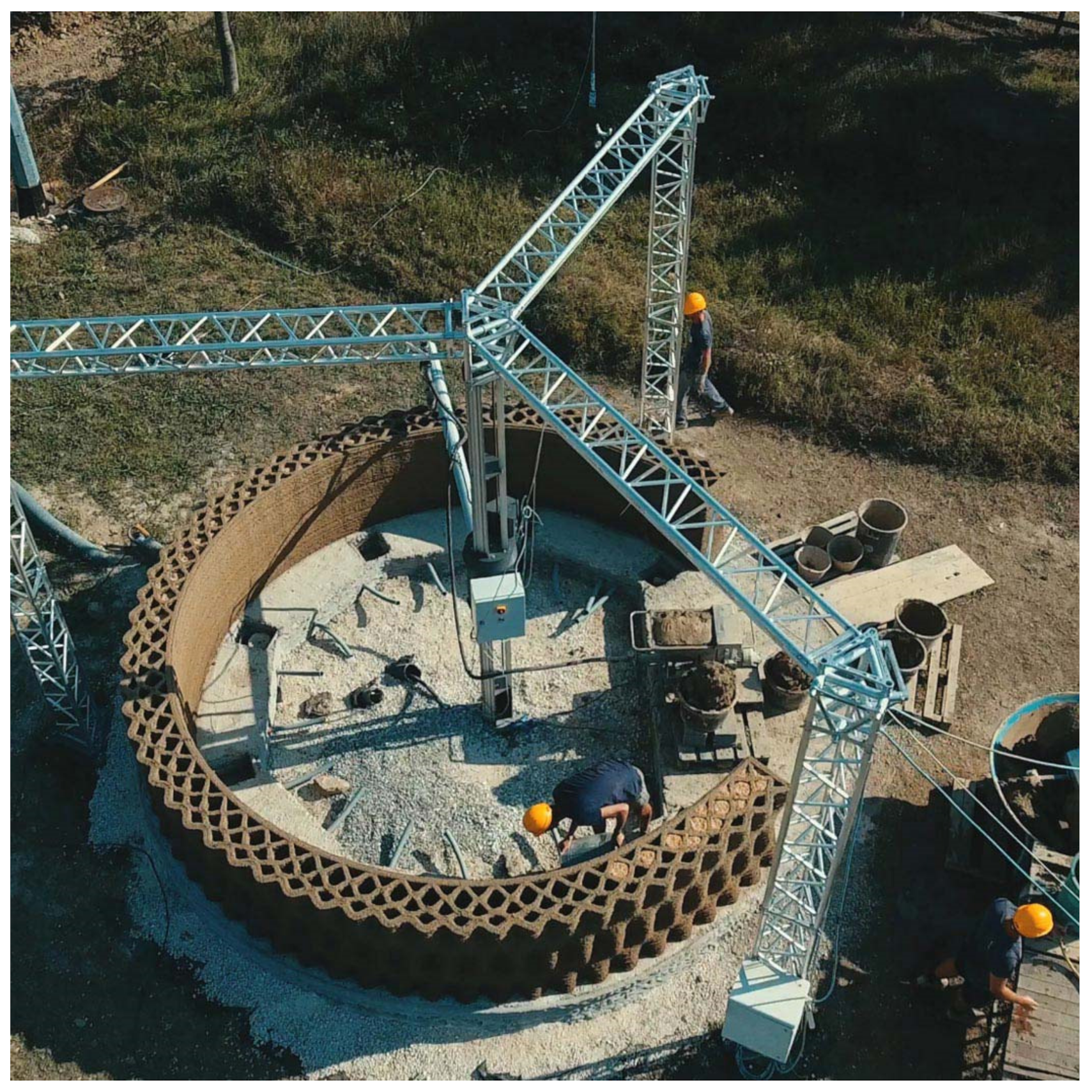
Located in Italy, World’s Advanced Saving Project (WASP) is another company in the 3D printing concrete industry [10]. Since starting the company in 2012, WASP has created their own printer, which helps print wall systems for buildings [10]. It appears this printer is mix between a robotic and a gantry-style printer [10]. The printer’s nozzle is supported by a central column, and it is also supported by a metal frame [10]. This printer consists of three legs and can be seen in Figure 9 [32]. Additionally, two metal frames are able to be connected together to create one large metal frame [10]. As a result, the total print area spans over 100 m2 (1075 ft2), but when only one metal frame is present, the print area spans about 50 m2 (538 ft2) [32].
To print their structures, WASP prints each wall layer by layer [10]. For the most part, WASP prints these wall structures on site [32]. However, the wall elements may be printed off site and then transported and assembled onsite if needed [32]. For example, the WASP printer is capable of printing in temperatures varying from 10 °C to 40 °C (50 °F to 104 °F) [32]. Thus, if the temperature drops below 10 °C (50 °F), the printer needs to print these elements indoor [32]. Additionally, the layer height for each extruded layer from the nozzle is a minimum of 9 mm (0.35 in.) [32]. The WASP printer is capable of printing at a maximum speed of 300 mm per second (11.8 in. per second) [32]. However, perhaps the most unique aspect of WASP’s printing is their mortar mixture. Unlike most other companies, WASP’s mixture is made almost entirely of naturally occurring materials [10]. For example, WASP’s mixture (from their Gaia project) consists of 25% soil from on site, 40% straw chopped rice, 25% rice husk, and 10% hydraulic lime [10].
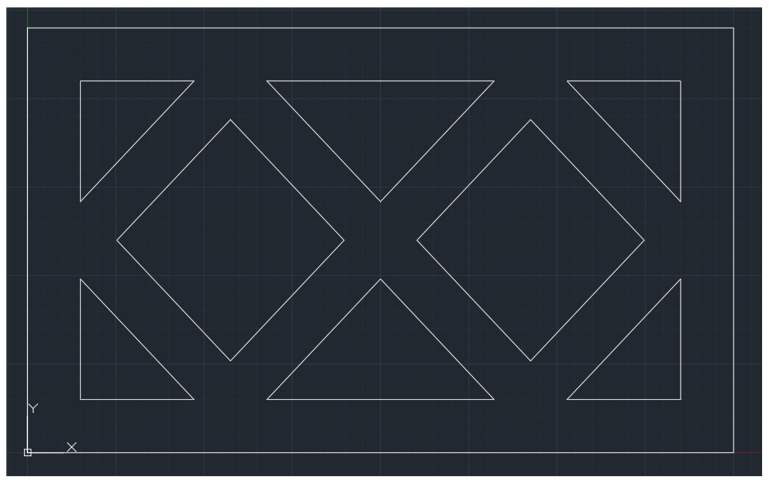
Also unique to WASP, they print their walls using a Cob design (meaning the inside cavity is separated by a weave like pattern) [33]. Additionally, no steel reinforcement is added to the wall as the shape of the wall itself is designed to provide all the necessary strength [10]. However, the inside cavity of the wall system is still filled with insulation in the form of rice husk [10]. A cob design, similar to WASP’s wall design, can be seen in Figure 10, which was created by the authors of this paper using AutoCAD software. This model was created using the information from Alhumayani.
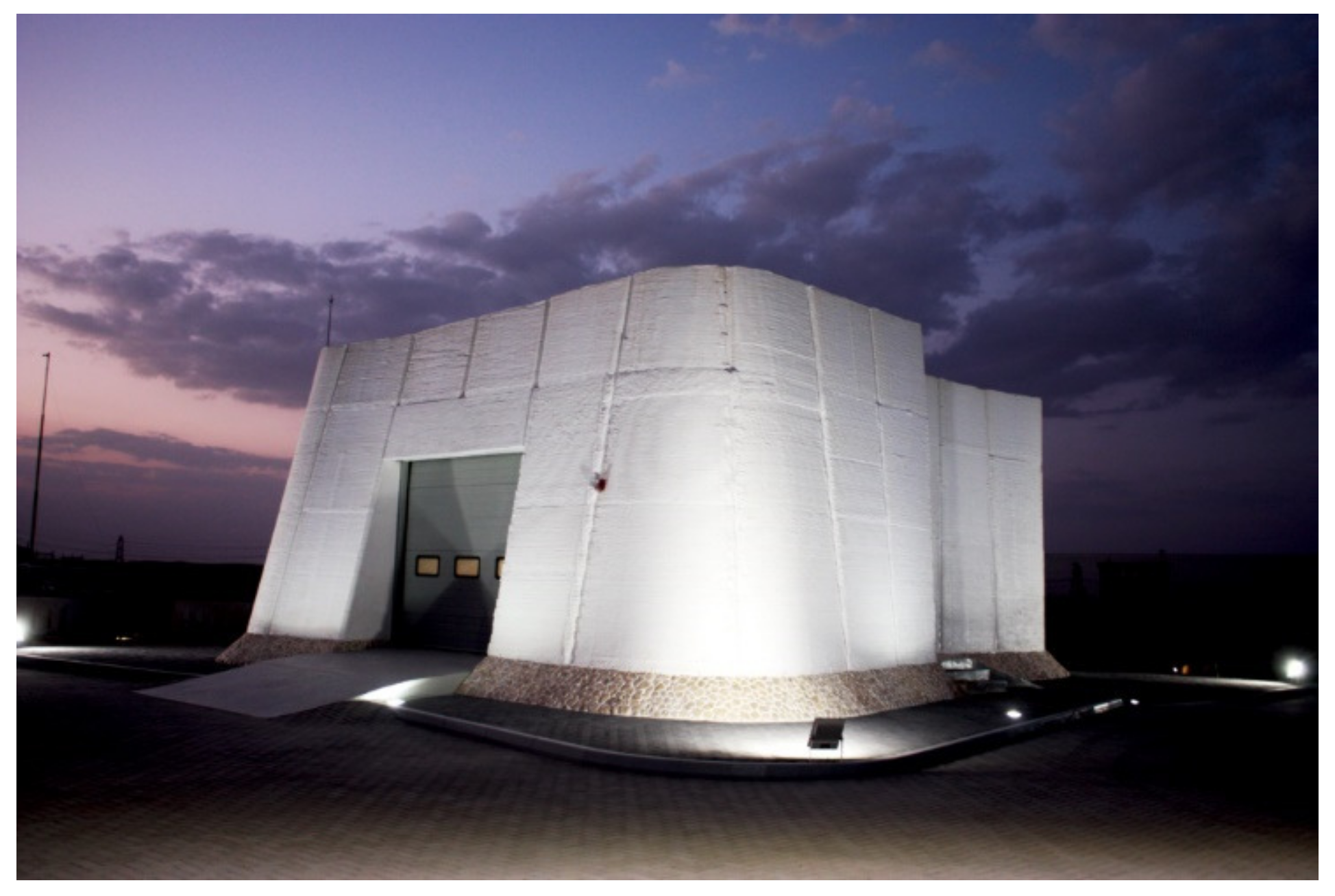
WASP was able to practice these printing methods during their 2018 project in Italy (named the Gaia project) [10]. This project lasted about 10 days, and the company was able to print the building with about 30 m2 (322 ft2) of wall area [10]. The building from this print can be seen in Figure 11.

2.1.6. SQ4D

SQ4D is another company from the United States of America that prints buildings [34]. SQ4D uses their own printer, named ARCS, to print wall systems for residential buildings [8]. Their printer, ARCS, is a gantry style printer that slides on a metal frame and is visible in Figure 12 [8]. SQ4D does not provide the maximum height or length the printer can reach.
Similar to other companies, SQ4D prints their walls by stacking layers of extruded concrete on top of each other [8]. Additionally, SQ4D prints structures on site [36]. Though they do not mention the speed of printing, it has been reported that they printed a 176.5 m2 (1900 ft2) in 48 hours of print time [37]. SQ4D does not specify the specific components of their mortar mixture. However, they do specify that their mortar mixture consists of Portland cement, aggregate (in the form of sand), and water [7]
SQ4D allows their printed walls to act as formwork [8]. The company mentions that the cavity present within the wall is able to be filled with structural columns (which can be inferred to be rebar and concrete), utilities, and insulation [7]. In addition to placing material inside the cavity, SQ4D also places metal staples (while it is still wet) into the concrete layers to better connect the inside and outside layer [8]. A wall similar to SQ4D’s wall design can be seen in Figure 13, which was created by the authors of this paper using AutoCAD software. This model was created using the information from SQ4D’s website.
SQ4D also has experience in printing structures. For example, according to Essop [37], they were able to print a 176.5 m2 (1900 ft2) home during an 8-day period. Again, during these 8 days, a total of about 48 printing hours were utilized to finish the walls of the house [37]. With the help of their ARCS printer, SQ4D stated that the total cost of material for the house was less than $6000 [37].

2.1.7. Huashang Tengda

Huashang Tengda is another Chinese company in the field of 3D printing concrete [12]. Similar to other companies, Huashang Tengda uses a gantry style printer to construct their walls [38]. However, the similarities to other companies stop there. Huashang Tengda utilizes a unique printing technique to construct their walls. Instead of printing the wall and then filling its cavities with reinforcement, utilities, and insulation, Huashang Tengda places their steel reinforcement and utilities in location prior to printing their wall [38]. Once both steel reinforcement and utilities are secured in place, Huashang Tengda uses their printer to print concrete on both sides of the reinforcement [38]. This secures the steel reinforcement and utilities in place and ensures they will not move. This technique of printing is mainly possibly due to Huashang Tengda’s printer design, which contains two nozzles separated at a distance to allow it to move over the tied steel reinforcement mesh, which allows the printer to stabilize the steel reinforcement as it prints [38].
Additionally, Huashang Tengda uses a C30 concrete in their printer, which contains coarse aggregates [12]. The Huashang Tengda printer is able to print each wall on site [12]. In addition to this, the Huashang Tengda printer is also able to accomplish the printing of their walls with the layer-by-layer technique seen with most other companies [38].
Huashang Tengda also has experience using their printing technique on real projects. For example, they were able to print the walls of a 400 m2 (4300 ft2) villa (spanning two stories) in 45 days [12]. They were able to complete the walls of this villa with the technique mentioned previously (placing the reinforcement and utilities first and then printing around them to hold them into place) [12]. At the time of its completion, Huashang Tengda reported that the villa could withstand an earthquake of magnitude 8.0 on the Richter scale [12].

2.2. Capabilities and Attributes of Robotic Arm Printers Used by Selected Companies

2.2.1. Apis Cor

Similar to ICON, Apis Cor produces printers and creates structures with these printers. Apis Cor has been active in printing buildings in several countries, including Russia, the United Arab Emirates, and the United States of America [5,6]. Unlike both ICON and COBOD, Apis Cor produces a robotic arm style printer, which can be seen in Figure 14 [39]. A robotic arm style printer has a main body with the arm extending outward from this main portion of the printer. Then, the printer head sits at the end of the arm [39]. According to Freire et al., a robotic arm style printer intrinsically possesses positive and negative attributes when compared to a gantry style printer, though one is not better than the other [17]. For example, many consider a robotic style printer easier to transport (especially when placed on wheels like Apis Cor’s printer) [17]. Additionally, robotic arm style printers contain more degrees of freedom for the printer head (ability to print more complex structures) and require less set up time [17]. However, with that being said, a robotic arm style printer also has negative attributes. For example, a robotic arm style printer typically has a smaller printer area than a gantry style printer, and when printing at certain heights, a robotic arm style printer’s nozzle tends to become angled [17]. The arm length of Apis Cor’s printer reaches to a minimum value of just over 4 m (13 ft) and reaches to a maximum value of just under 8.5 m (28 ft) [6]. Additionally, the maximum height possible with an Apis Cor printer is just under 3.1 m (just over 10 ft) [6]. In all, this leads to a maximum operating area of about 132 square m (1421 square ft), which helps the printer reach a maximum output of 100 square m (1079 square ft) per day [6].
Just like ICON and COBOD, Apis Cor’s printer lays beads of mortar down layer by layer on site [39]. Apis Cor is able to utilize a maximum print speed of about 165 mm per second (6.5 in. per second) from their printer [39]. Flavio Craveiro et al. state that concrete or geopolymer can be used as a printing material with Apis Cor’s printer [39].
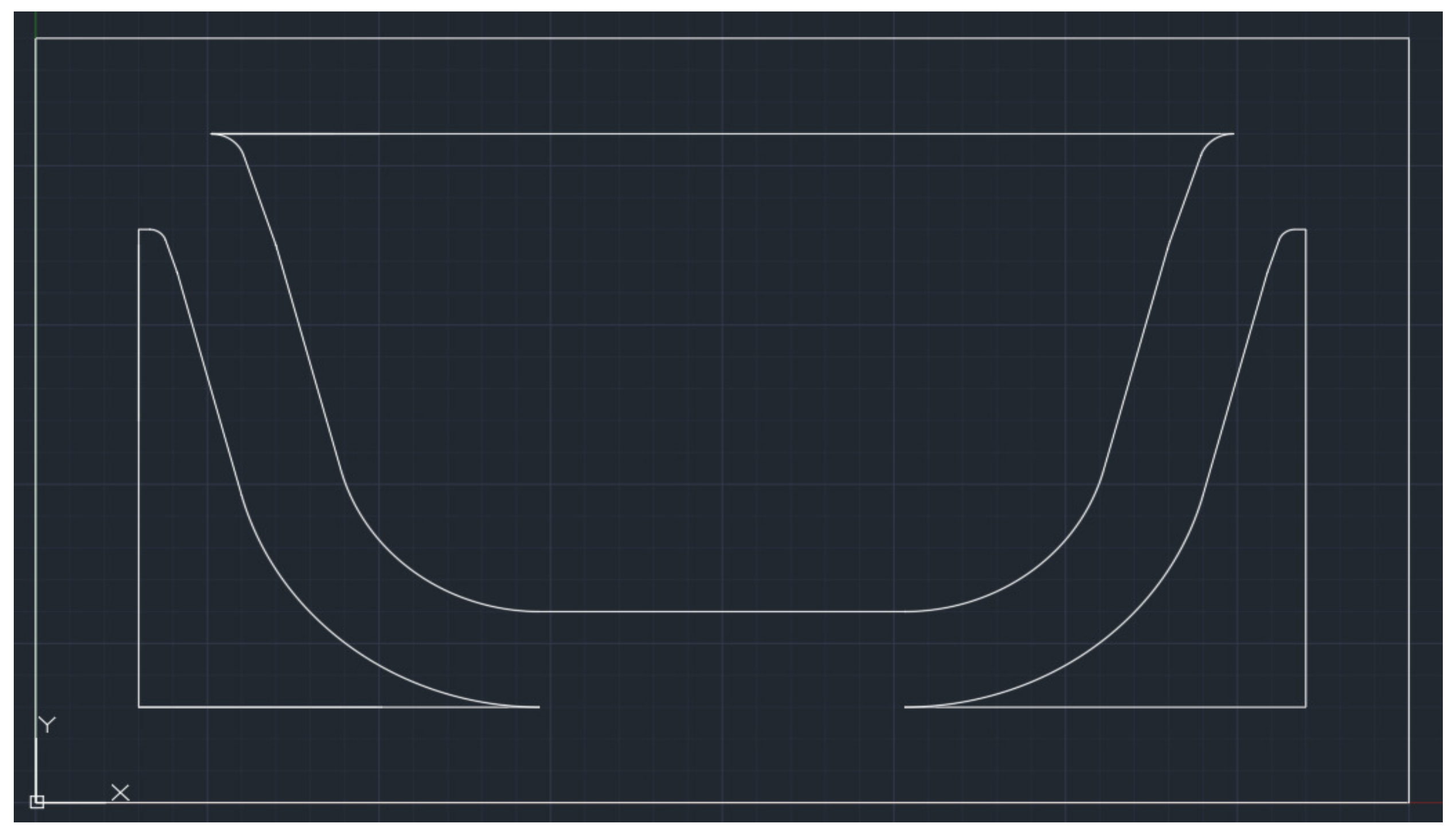
Additionally, Apis Cor also prints its walls to act as a stay-in-place formwork [5]. This process by which they create this formwork is unique to Apis Cor. Instead of creating typical cavities in their walls like most other companies, Apis Cor prints their walls to look and act like concrete masonry units with cavities [5]. This practice yields several benefits to the company (or anyone else that uses their printers). First, outside contractors that build using these printers have prior knowledge of building with concrete masonry unit. This means once the printing is complete, the contractors can easily finish the structure as they would with any other conventional building [5]. Second, the print structure, mimicking concrete masonry unit, allows for easier approval from the local government to use this technology [5]. Since local governments are familiar with the process of building with concrete masonry unit, it can be inferred that they will better understand this printing process and be more likely to approve its use. Once the wall structure is printed, Apis Cor places vertical reinforcement into several of the wall’s cavities and then fills that cavity with concrete [5]. In the cavities not filled with reinforcement, Apis Cor fills these cavities with the same insulation found in concrete masonry unit walls [41]. More specifically, they have shown to be able to use spray polyurethane foam, mineral wood, polystyrene insulation board, polyisocyanurate insulation boards, or any other insulation that is typically found in concrete masonry unit walls [42]. A drawing mimicking Apis Cor’s wall design can be seen in Figure 15, which was created by the authors of this paper using AutoCAD software [5,43].
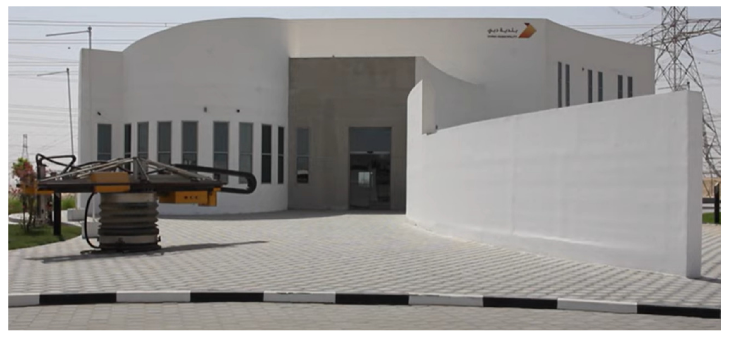
As previously mentioned, Apis Cor has printed structures in several countries [5,6]. One of the buildings they printed is an administrative building in Dubai [5], where the building itself measured about 9.5 m (31 ft) tall and just under 641 m2 (6900 ft2) [5]. At the time of its completion, this was the largest building printed on site in the world [5]. A picture of this building can be seen in Figure 16. Importantly, Pessoa et al. mention that this structure was uncovered while being printed on site, meaning it was able to print in the harsh conditions of Dubai [44].

2.2.2. CyBe

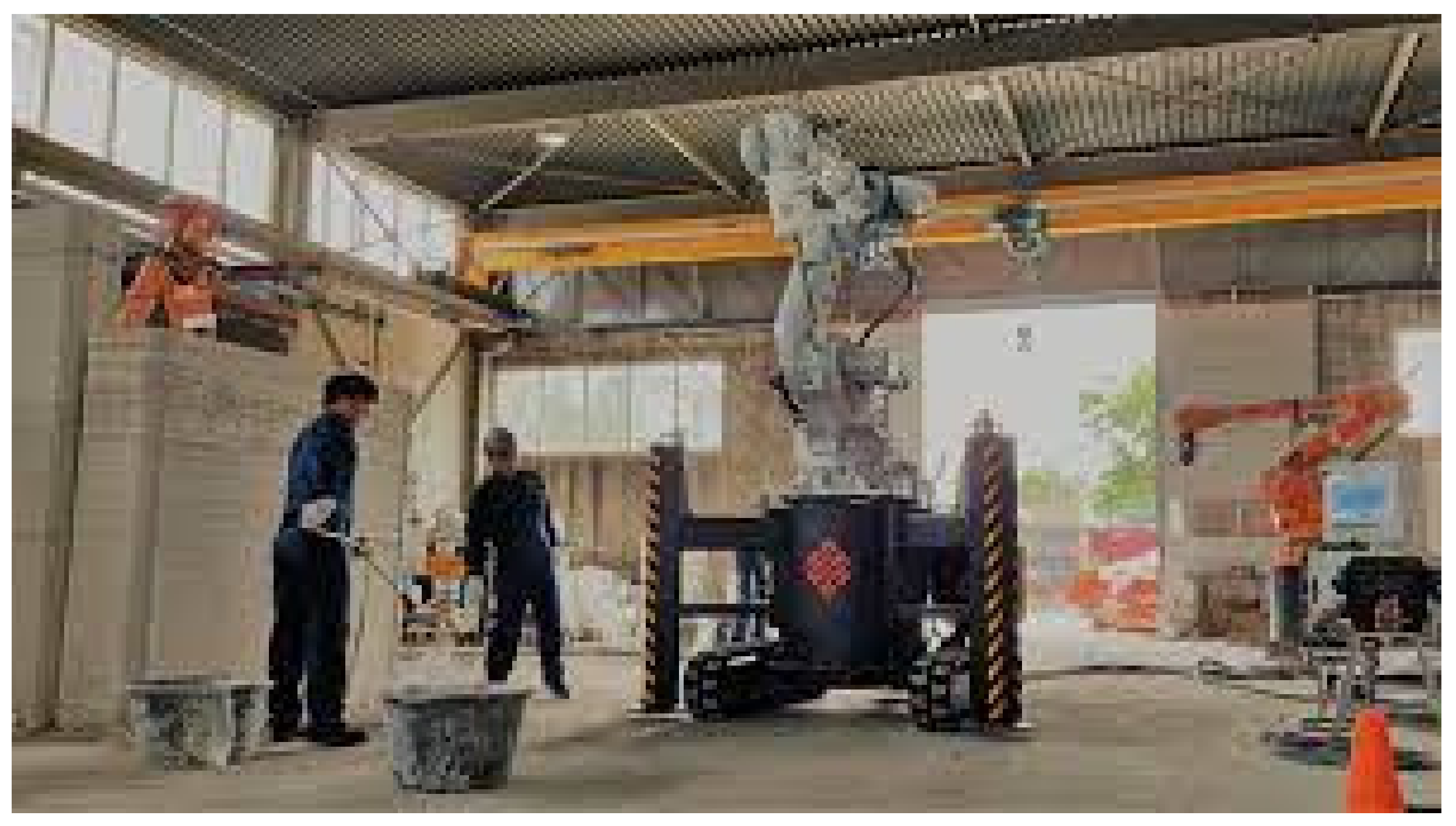
CyBe is another company that has helped further innovation in the field of printed buildings. CyBe was founded in November of 2013 in the Netherlands [45]. Similar to Apis Cor, CyBe primarily uses a robotic arm style printer that can be easily moved via CyBe’s “crawler system,” which are tracks placed on the bottom of the printer to allow it to move (though they make and use a gantry style printer as well) [46]. The CyBe printer can be seen in Figure 17. The robotic arm on CyBe’s printer possesses many of the same benefits and drawbacks discussed before with the Apis Cor printer.
CyBe has also designed a mortar mix to specifically be used with their printer–”CyBe Mortar” [48]. The printer is able to extrude mortar with a bead thickness up to 50 mm (2 in.) at a maximum rate of about 500 mm per second (19.7 in. per second) [39]. CyBe has the ability to print walls on or off site [49].
CyBe prints hollow walls; thus, as with other companies’ wall systems, their printed walls act as stay-in-place formwork [49]. Once printed, it can be inferred that the wall’s cavity is filled with mortar [49].
In the summer of 2018, CyBe was able to print an 80 m2 (861 ft2) house in Saudi Arabia [49]. In all, CyBe printed a total of 27 walls and 21 parapets in 1 week [49]. On this project, CyBe was able to print these elements on site [49]. In addition to this house, CyBe completed the first ever printed laboratory with the footprint encompassing an area of about 168 m2 (1800 ft2) [50]. According to CyBe [50], they were able to complete the walls for this structure in 46 h of printing time [50]. While printing the walls on site, CyBe covered the printing area to protect the structure from the location’s weather [50]. A picture of this laboratory can be seen in Figure 18.

2.3. Comparative Evaluation of the 3D Printing Systems and Printed Walls

Companies use two distinct types of systems to maneuver their printer heads: gantry-style printers and robotic arm printers. More specifically, ICON, COBOD, Black Buffalo, WinSun, WASP, SQ4D, and Huashang Tengda use a type of gantry frame printers, whereas Apis Cor and CyBe primarily use robotic arm style printers. As a result, companies that use gantry printers may have an easier time perfecting print quality, as the print head is continuously vertical while printing [17]. On the other hand, companies that use robotic arm printers find improved freedom in the range of motion of their printer, easier transportation, and easier set up of their printer (since the printer can be placed on wheels and move) [17]. Therefore, both types of printers possess advantages and disadvantages, which allows companies to specialize in printing certain types of structures depending on the system they use.

2.4. Other Attributes of Gantry Frame Printers

In most cases, all the companies that use a gantry frame printer utilize a cement-based mortar that prints walls in multiple layers [24]. As with most cement-based products, these walls form cracks as they settle. For many companies, this is a challenge. In these cracks, water will gather and (in cold environments) freeze, further expanding the cracks. As a result of these cracks, the printed layer may start to deteriorate.
One common aspect of each company’s wall cross section configuration is that the walls include exterior and interior surfaces as well as webs that connect these surfaces. This is done so that these walls will essentially act as formwork for placement of the concrete and insulation [20]. Accordingly, most companies print the walls with cavities within the cross section and then fill these cavities with insulation, concrete, and reinforcement [20]. However, there are a few exceptions to this. For example, WASP uses soil, straw chopped rice, and rice husk in their mortar mixture [10]. Even with this, they still leave cavities present to be filled with insulation [10]. Therefore, it can be inferred that WASP excels in the sustainability of their structures, whereas other companies may not perform as well with respect to this aspect.
On the other hand, many gantry printer systems possess different printing space dimensions. More specifically, some printing companies utilize a modular design onto their gantry printer [24]. For example, ICON, COBOD, WASP, Black Buffalo, and SQ4D all allow additional metal framing to be attached to their gantry frame [24]. As a result, this extends the printable area of the printer. However, these companies accomplish this in different ways. More specifically, ICON puts their gantry system on wheels so there is no restriction on the printable length [18]. On the other hand, companies like Black Buffalo, WASP, and COBOD add additional framing to their gantry system to expand the printable area [24]. Due to these attributes, more companies use gantry-style printers for the printing of walls. Not only do these printers possess a larger print area, but the printer does not need to be moved during the printing process [24].

2.5. Other Attributes of Robotic Arm Printers

Of the companies discussed, two companies use a robotic arm printer: Apis Cor and CyBe [17]. Though they both use the same style of printer, each company’s process and product has its similarities and differences. For the most part, Apis Cor and CyBe follow many of the same processes. For example, they both print their walls as formwork that is inferred to be later filled with reinforcement, concrete, and insulation [5,49]. However, the main difference during the completion of their projects has been the mobility of their printer. During Apis Cor’s projects, they did not place their printer on wheels [43]. Instead, they placed their printer down to print a section of a wall and then manually moved the printer with a crane so the printer could complete subsequent sections of the wall [43]. On the other hand, CyBe places their robotic arm printer on wheels [46]. Therefore, the CyBe printer is able to print subsequent sections because of its wheels [46]. Placing the printer on wheels seems like a much more efficient design, and, as a result, Apis Cor now has the ability to place their printer on wheels for their future projects [43]. As a result of these attributes, robotic style printers have the ability to print a larger variety of structures. For example, robotic arm style printers can be used to print more ornamental structures or furniture. This is due to robotic arm style printers containing more degrees of freedom [17].

2.6. Challenges Associate with the Current State of Practice

One of the largest concerns surrounding the industry is the placement of concrete and insulation within the cavity of the printed walls. Therefore, companies have developed different wall systems to maximize the structural resistance while limiting the amount of thermal bridging present. To reduce thermal bridging, some companies maintain no direct connection between the interior and exterior faces of their printed wall structure. For example, ICON uses a design that leaves a slot for vertical reinforcement (and the placement of concrete inside of it) without any contact to their adjacent vertical layer [20]. Therefore, this avoids any thermal bridging. Similarly, COBOD utilizes a similar technique, where the insulation and reinforcement cavities are separate with no contact between the inside and outside wall [25]. On the other hand, companies like Apis Cor, SQ4D, WinSun, and Black Buffalo all have utilized a diagonal pattern in the middle of their wall at some point [43]. This provides spaces on the inside of the wall for reinforcement, concrete, and insulation. Though the diagonal portion touches both the inside and outside walls of the cavity, which could create thermal bridging, this design possesses several benefits. For example, this design allows the wall to be skinnier (taking up less room) because the reinforcement and insulation are placed next to each other instead of one in front of the other. This design also provides clear gaps for utility lines (such as plumbing, electrical, and HVAC systems) to be placed into the wall and run throughout the structure.
For the most part, companies use insulation and reinforcement in their walls in similar ways. They first print the concrete formwork for the walls (leaving the necessary room for windows, doors, and utilities). Following this, they place in the necessary vertical reinforcement and concrete into the wall cavities [25]. Then, insulation is filled into the remaining portions (cavities) of the wall [25]. Finally, if the wall contains utilities, the company will then place in the required utilities into the wall’s cavity [25]. Overall, this seems to be a sufficient technique for walls, as the walls of each house are able to have the structural stability (due to the role of concrete and reinforcement) along with insulation meant to satisfy the code requirements.
A common misconception is that 3D-printed buildings are completely 3D printed. The fact is that all of the companies mentioned use conventional construction techniques and materials for all other parts of their structure, except the wall structure [20]. This includes construction of their roof and the placement of their windows [20]. Currently, 3D-printed buildings contain 3D-printed walls. In order to do this, almost every company prints formwork that is then filled with insulation, reinforcement, and concrete. However, finishing interior surfaces, thermal insulation, waterproofing, mechanical installation, electrical installation, and plumbing installation are typically completed using conventional practices, which takes months after the walls are erected [20]. On the other hand, it is conceivable that in the future these companies will attempt to automate more of the construction process as they master the printing of their walls, and perhaps employing some aspects of robotic construction.

2.7. Approximate Thermal and Structural Evaluation

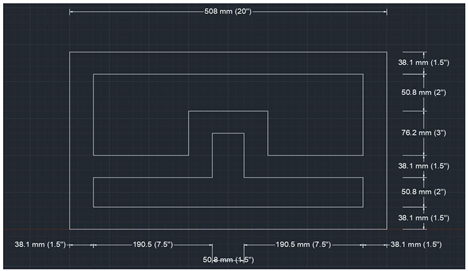
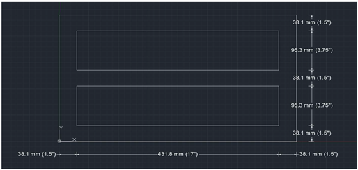
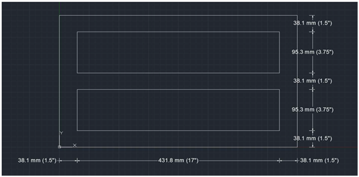
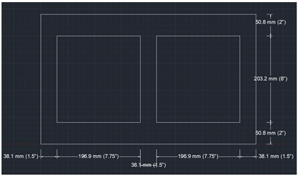
One aspect of interest in this study is the comparison of the drawings of each wall with respect to thermal bridging and structural resistance. In order to obtain a general idea of each company’s wall strength, the moment of inertia of each drawing was estimated, as is presented in this section. Thus, the shapes making up each wall section were simplified to allow for the necessary calculations to be applied to each wall. Additionally, the x-axis is taken to be the horizontal direction along the length of the wall, while the y-axis is taken to be perpendicular to the surface of the wall, i.e., both in the cross-sectional plane of the wall. Thus, the centroid for each nonsymmetrical wall section was also calculated to assist in the determination of each wall’s moment of inertia calculation. Following this, the farthest point on each wall was also determined, as is indicated in Table A1 through 7 as “x” and “y.” With the moment of inertia and each wall’s farthest point from the centroid, the stress due to any moment (called “M” that is applied about the x axis) that would be generated in each wall (without any additional reinforcement present) was determined using the flexural formula (which is represented as equation 1 below). This allowed each wall’s stress to be represented in terms of a moment M. In all, the study will show the amount of stress developed in each wall’s formwork due to any applied moment.
σ = M y I
As displayed in Table A1 through 7, certain wall designs performed better than others when calculating each wall’s stress based on its shape alone (this calculation also assumed a bead thickness of 38.1 mm (12 in.) for the walls, a width of 508 mm (20 in.) for all walls, and a depth of 304.8 mm (12 in.) for all walls). For example, the walls drawn to mimic Black Buffalo, WinSun, and Apis Cor’s wall systems performed the best (produced the least amount of stress) in the x direction. In particular, each of these wall systems have significant hollow sections in the center of the wall, which can logically be inferred as a location to put steel reinforcement and insulation [5,11,28]. As a result of these significant hollow sections, the moment of inertia in the x direction is larger for these walls, which, in turn, leads to a decreased stress value.
The only company that was not able to be included for this moment of inertia check was Huashang Tengda, due to its printer using metal mesh to combine both sides of its walls [38]. As a result, this wall system could not be effectively approximated (in a similar way the other companies were approximated). It should also be noted that certain assumptions were made when drawing the walls, which were drawn to the best of the author’s ability from the cited resources. First, some companies do not connect the interior and exterior face of their wall via concrete on the sides, and for some companies it is unclear if the exterior is connected to the interior. However, for this study, each wall drawn connected these two faces to remain consistent between walls [20]. Similarly, certain companies have used walls that are similar to the walls used by another company. The calculations for the walls mimicking these company’s designs were grouped together and taken to be the same as each other: i.e., the walls drawn to mimic Black Buffalo and WinSun’s walls were grouped together, just as the walls drawn to represent SQ4D and CyBe’s walls were grouped together. It should be noted that CyBe’s walls possess a thinner concrete bead on the bottom corners than SQ4D’s wall [8,50]. In this study, the wall that was drawn to mimic the two company’s wall was assigned a thickness of 114.3 mm (4.5 in). However, the two walls were determined to be similar enough to be grouped together for this study. It should also be noted that the wall drawn to mimic Black Buffalo’s wall was taken to have a diagonal pattern in their wall as it was mentioned they have previously used this design [28]. Additionally, all of the wall systems mentioned fill a portion of the wall cavities with concrete. In order to maintain consistency and provide conservative calculations, the moment of inertia and stress values for each drawing were calculated without the presence of concrete and reinforcement in these cavities. In all, the walls drawn to mimic Black Buffalo, WinSun, and Apis Cor’s wall systems resulted in the lowest stress values, but every other wall drawn produced stress values in the 1.9 × 10⁻⁷ *M MPa range as can be seen in Appendix A. More specifically, the wall drawn to mimic ICON’s wall system produced the largest moment of inertia, but due to its asymmetrical shape, it also produced the highest distance from the center of mass. As a result, it resulted in a stress of 1.96 × 10⁻⁷ *M MPa.
Every company’s wall design also faces different results in terms of its thermal performance. Some companies’ wall systems inherently contain fewer thermal bridging locations. For example, it would be expected that the walls drawn to mimic ICON and COBOD’s wall systems would result in the lowest amount of thermal loss, because both wall systems possess two gaps, which allow insulation to be placed to completely insulate the interior wall layer from the exterior layer without additional contact [20,25]. Conversely, it can be inferred that the walls drawn to mimic Apis Cor, CyBe, and SQ4D’s walls behave with slightly more thermal loss due to more thermal bridging locations being present. The increased heat transfer in these three wall systems results from additional concrete connecting the inside layer to the outside layer as is seen from the figures drawn to mimic their wall systems [8,43,49]. This results in additional thermal bridging and more heat transfer. Based on thermal bridging, the walls drawn to mimic Black Buffalo, WinSun, and WASP’s printed wall systems would be expected to experience more heat transfer than the walls drawn to mimic Apis Cor, CyBe, and SQ4D’s wall systems. The walls drawn to mimic Black Buffalo, WinSun, and WASP’s wall systems all contain multiple thermal bridging locations due to their pattern, which is depicted in each company’s respective figures [28,33,51]. As a result, the pattern results in additional contact between the interior and exterior wall, which leads to more thermal bridging and heat transfer. Between the walls drawn to mimic Black Buffalo and WASP’s wall systems, it appears that wall drawn to mimic WASP’s would experience more thermal bridging because it possesses more diagonals per wall section (thus more locations for the concrete to connect interior and exterior wall).
In all, the wall system’s shape and configuration of sections play a vital role in the wall’s strength and thermal performance. As indicated by the qualitative comparison and evaluation conducted in this paper, certain company’s walls outperform other company’s walls in terms of strength, but the opposite may hold true for thermal performance. As a result, companies must find the perfect balance between maximizing strength while minimizing thermal bridging in their walls. Of course, it should be noted that for an accurate comparison of all these wall performances, detailed finite element modeling is necessary, which is beyond the scope of this preliminary study, which has only displayed this issue by the qualitative comparison and evaluation performed. On the other hand, for a more practical application of the 3D Concrete Printing in home building and other construction projects, the companies should develop design aids so that design professionals can easily find section properties, as is the case for precast concrete, timber, and steel sections.

3. Concluding Remarks

All of the companies discussed are transforming the construction industry. Though companies may have different processes, they all share common goals: reduce construction costs, decrease construction material and time, and improve construction automation. Almost every industry has implemented automation. As a result, the construction industry must catch up. These companies are attempting to bring 3D-printing automation into the construction of buildings. Though the adoption of this technology may not be completely feasible and widely accepted currently, these companies are continually addressing practical printing hurdles so that the construction industry can start to embrace this new technology of building with concrete.
From this state of the practice study reported above, it is clear that there are several methods to accomplish the printing of buildings. For example, companies such as ICON, COBOD, and several others that utilize a gantry style printer, have found success with this printer style. On the other hand, other companies that utilize a robotic arm style printer, e.g., Apis Cor and CyBe, show different advantages such as printing complex details. From this literature review, it was found that each type has advantages and disadvantages. For example, gantry-style printers tend to experience quality printed layers, whereas the robotic arm style printers experience increased flexibility in mobility and printing. From this, it can be inferred that no one option is superior to the other. Instead, each company’s specific printer has its advantages and disadvantages. For this reason, in the future, a company may choose to use a robotic arm style printer for a specific job and then switch to a gantry style printer on a different job, or have the robotic arm integrated with a gantry frame system.
Additionally, a preliminary structural and thermal analysis was performed. From the simplification of the wall shapes, the moment of inertia was found for the drawing that mimics each wall system. From these values, the stress developed in these walls due to an applied moment and was able to be found. From these results, it was found that Black Buffalo, WinSun, and Apis Cor’s walls resulted in the lowest stress developed due to an applied moment. In addition to this, a qualitive analysis was performed for the amount of thermal bridging locations in each wall system. From this, it was found that ICON and COBOD’s wall designs would result in the least amount of thermal bridging.
While 3D concrete printing is a possible solution for the many issues that the construction industry faces, there are still many issues related to this technology that need to be solved in the future. For example, there must be a standardized method for measuring the ideal pumpability for concrete fed into the printer [15]. Additionally, companies must work to make the software and hardware of the printer more user friendly. This would reduce the learning curve so more people could learn how to concrete print.

4. Discussion

In this review, companies were split into two categories based on the style of printer they utilized (robotic arm style printer or gantry style printer). However, amongst the companies in each group, there are specific differences that differentiate each company. Additionally, amongst the companies that use a type of gantry style printer, all but one company uses a cement-based mortar (that company being WASP). This is a critical difference that not only affects the performance of the wall (specifically thermal insulation and structural stability) but also illustrates the company’s overall sustainability outlook. In the future, companies will have to weigh the costs and benefits of each option and each ingredient they place in their concrete (specifically compared to other companies) and decide on that ingredient’s overall content in their concrete.
In all, every company mentioned in this review has progress to make, as the technology has just been born and there is much to learn. Each company performs well in specific categories and has developed a niche. Accordingly, most companies will continue to improve their technology and grow, pushing the construction industry toward a completely automated industry. All companies need to expand the availability of their design aids and component and section property tables.

Author Contributions

Conceptualization, N.D.B. and A.M.M.; methodology, N.D.B. and A.M.M.; software, N.D.B.; validation, A.M.M.; formal analysis, N.D.B. and A.M.M.; investigation, N.D.B. and A.M.M.; resources, N.D.B. and A.M.M.; data curation, N.D.B. and A.M.M.; writing—original draft preparation, N.D.B.; writing—review and editing, A.M.M.; visualization, N.D.B.; supervision, A.M.M.; project administration, A.M.M. All authors have read and agreed to the published version of the manuscript.

Funding

This research received no external funding.

Data Availability Statement

All data from this research, is provided within this manuscript.

Conflicts of Interest

The authors declare no conflict of interest.

Appendix A

Table A1. ICON wall calculations.
ICON
Drawing Mimicking Printed Shape [20]
Buildings 13 00106 i001
Approximated Shape
Buildings 13 00106 i002
Centroid Calculation
Shapex [mm (in.)]y [mm (in.)]A [mm^2 (in.^2)]xA [mm^3 (in.^3)]yA [mm^3 (in.^3)]
1.00254.00488.9519,354.804,916,119.209,463,529.46
2.00254.0019.0519,354.804,916,119.20368,708.94
3.0019.05152.408709.66165,919.021,327,352.18
4.00488.95152.408709.664,258,588.261,327,352.18
5.00133.35107.957258.05967,860.97783,506.50
6.00374.65107.957258.052,719,228.43783,506.50
7.00209.55146.051451.61304,184.88212,007.64
8.00298.45146.051451.61433,233.00212,007.64
9.00254.00184.154838.701,229,029.80891,046.61
Sum 78,386.919,910,282.815,369,017.6
Centroid (x)
[mm (in)]
254 (10)
Centroid (y)
[mm (in)]
196.07 (7.72)
Moment of Inertia/Stress Calculation
ShapeArea
[mm^2 (in.^2)]
dx
[mm (in.)]
dy
[mm (in.)]
Adx^2
[mm^4 (in.^4)]
Ady^2
[mm^4 (in.^4)]
Ix
[mm^4 (in.^4)]
Iy
[mm^4 (in.^4)]
1.0019,354.8089.660.00155,598,545.140.002,341,301.77416,231,425.60
2.0019,354.80177.040.00606,626,917.920.002,341,301.77416,231,425.60
3.008709.6643.69234.9516,623,617.170.0037,929,088.661,053,585.80
4.008709.6643.69234.9516,623,617.170.0037,929,088.661,053,585.80
5.007258.0588.14120.6556,382,750.530.00702,390.5311,238,248.49
6.007258.0588.14120.6556,382,750.530.00702,390.5311,238,248.49
7.001451.6150.0444.453,634,543.210.00175,597.63175,597.63
8.001451.6150.0444.453,634,543.210.00175,597.63175,597.63
9.004838.7011.940.00689,591.410.00585,325.446,503,616.03
Sum 916,196,959.60.082,882,082.6863,901,227.0
Ix
[mm^4 (in.^4)]
9,990,000,000 (2400.3) x
[mm (in.)]
254 (10)
Iy
[mm^4 (in.^4)]
864,000,000 (2075.5) y
[mm
(in.)]
196.088 (7.72)
σ
[MPa (ksi)]
0.000000196M
(0.0032M)
Table A2. PERI/COBOD wall calculations.
PERI/COBOD
Drawing Mimicking Printed Shape [25]
Buildings 13 00106 i003
Approximated Shape
Buildings 13 00106 i004
Moment of Inertia/Stress Calculation
ShapeArea
[mm^2 (in.^2)]
dx
[mm (in.)]
dy
[mm (in.)]
Adx^2
[mm^4 (in.^4)]
Ady^2
[mm^4 (in.^4)]
Ix
[mm^4 (in.^4)]
Iy
[mm^4 (in.^4)]
1.00154,838.400.000.000.000.001,198,746,505.733,329,851,404.80
2.00−82,257.9066.680.00−365,682,070.050.00−62,190,802.22−1,278,092,702.39
Sum −365,682,070.050.001,136,555,703.502,051,760,783.57
Ix
[mm^4 (in.^4)]
770,000,000 (1852) x [mm (in.)]254 (10)
Iy
[mm^4 (in.^4)]
2,100,000,000 (4929.4) y [mm (in.)]152.4 (6)
σ [MPa (ksi)]0.000000198M
(0.0032M)
Table A3. Black Buffalo/WinSun wall calculations.
Black Buffalo/WinSun
Drawing Mimicking Printed Shape [28,31]
Buildings 13 00106 i005
Approximated Shape
Buildings 13 00106 i006
Moment of Inertia/Stress Calculation
ShapeArea
[mm^2 (in.^2)]
dx
[mm (in.)]
dy
[mm (in.)]
Adx^2
[mm^4 (in.^4)]
Ady^2
[mm^4 (in.^4)]
Ix
[mm^4 (in.^4)]
Iy
[mm^4 (in.^4)]
1.00154,838.400.000.000.000.001,198,746,505.733,329,851,404.80
2.00−79,999.840.00117.480.00−1,104,028,882.52−275,267,577.39−258,332,369.37
Sum −1,104,028,882.52923,478,928.343,071,519,035.43
Ix
[mm^4 (in.^4)]
924,000,000 (2218.7) x
[mm (in.)]
254 (10)
Iy
[mm^4 (in.^4)]
1,970,000,000 (4727) y
[mm (in.)]
152.4 (6)
σ [MPa
(ksi)]
0.000000165M
(0.0027M)
Table A4. WASP wall calculations.
WASP
Drawing Mimicking Printed Shape [33]
Buildings 13 00106 i007
Approximated Shape
Buildings 13 00106 i008
Moment of Inertia/Stress Calculation
ShapeArea
[mm^2 (in.^2)]
dx
[mm (in.)]
dy
[mm (in.)]
Adx^2
[mm^4 (in.^4)]
Ady^2
[mm^4 (in.^4)]
Ix
[mm^4 (in.^4)]
Iy
[mm^4 (in.^4)]
1.0019,354.80133.350.00344,171,360.040.002,341,301.77416,231,425.60
2.008709.660.00234.950.00480,788,919.7137,929,088.661,053,065.51
3.008709.660.00234.950.00480,788,919.7137,929,088.661,053,065.51
4.008709.660.0078.320.0053,419,557.3937,929,088.661,053,065.51
5.008709.660.0078.320.0053,419,557.3937,929,088.661,053,065.51
688,363,531.661,068,424,446.37156,398,958.17836,677,194.38
Ix
[mm^4 (in.^4)]
845,000,000 (2029.5) x
[mm (in.)]
254 (10)
Iy
[mm^4 (in.^4)]
1,910,000,000 (5722) y
[mm (in.)]
152.4 (6)
σ
[MPa (ksi)]
0.00000018M
(0.003M)
Table A5. SQ4D/CyBe wall calculations.
SQ4D/CyBe
Drawing Mimicking Printed Shape [8,50]
Buildings 13 00106 i009
Approximated Shape
Buildings 13 00106 i010
Centroid Calculation
Shapex
[mm (in.)]
y
[mm (in.)]
A
[mm^2 (in.^2)]
xA
[mm^3 (in.^3)]
yA
[mm^3 (in.^3)]
1.00254.0019.0519,354.804,916,119.20368,708.94
2.00254.00285.7519,354.804,916,119.205,530,634.10
3.0019.05152.408709.66165,919.021,327,352.18
4.00488.95152.408709.664,258,588.261,327,352.18
5.00127.0076.2013,548.361,720,641.721,032,385.03
6.00381.0076.2013,548.365,161,925.161,032,385.03
7.00254.00190.5034,838.648,849,014.566,636,760.92
Sum0.000.00118,064.2829,988,327.1217,255,578.39
Centroid (x)
[mm (in.)]
254.00
Centroid (y)
[mm (in.)]
146.15
Moment of Inertia/Stress Calculation
ShapeArea
[mm^2 (in.^2)]
dx
[mm (in.)]
dy
[mm (in.)]
Adx^2
[mm^4 (in.^4)]
Ady^2
[mm^4 (in.^4)]
Ix
[mm^4 (in.^4)]
Iy
[mm^4 (in.^4)]
1.0019,354.80127.100.00312,685,538.890.002,341,301.77416,231,425.60
2.0019,354.8088.800.00152,607,026.700.002,341,301.77416,231,425.60
3.008709.666.25234.95339,775.05480,786,422.3237,929,088.661,053,585.80
4.008709.666.25234.95339,775.05480,786,422.3237,929,088.661,053,585.80
5.0013,548.3669.95127.0066,299,927.68218,521,498.446,555,644.9535,691,844.75
6.0013,548.3669.95127.0066,299,927.68218,521,498.446,555,644.9535,691,844.75
7.0034,838.6444.350.0068,512,240.790.0067,429,490.95151,716,354.63
Sum 667,084,211.991,398,615,841.52161,081,561.711,057,670,275.03
Ix
[mm^4 (in.^4)]
828,000,000 (1989.7) x
[mm (in.)]
254 (10)
Iy
[mm^4 (in.^4)]
2,460,000,000(5901.3) y
[mm (in.)]
158.6 (6.25)
σ
[MPa (ksi)]
0.000000192M (0.00314M)
Table A6. Apis Cor wall calculations.
Apis Cor
Drawing Mimicking Printed Shape [43]
Buildings 13 00106 i011
Approximated Shape
Buildings 13 00106 i012
Moment of Inertia/Stress Calculation
ShapeArea
[mm^2 (in.^2)]
dx
[mm (in.)]
dy
[mm (in.)]
Adx^2
[mm^4 (in.^4)]
Ady^2
[mm^4 (in.^4)]
Ix
[mm^4 (in.^4)]
Iy
[mm^4 (in.^4)]
1.0019,354.80133.350.00344,171,360.040.002,341,301.77416,231,425.60
2.0019,354.80133.350.00344,171,360.040.002,341,301.77416,231,425.60
3.008709.660.00234.950.00480,786,422.3237,929,088.661,053,585.80
4.008709.660.00234.950.00480,786,422.3237,929,088.661,053,585.80
5.004838.7095.25152.4043,899,428.98112,382,484.91585,325.446,503,616.03
6.004838.7095.25152.4043,899,428.98112,382,484.91585,325.446,503,616.03
7.005806.440.00107.950.0067,663,621.1211,238,248.49702,390.53
8.005806.440.00107.950.0067,663,621.1211,238,248.49702,390.53
9.009677.4095.250.0087,798,816.340.001,170,650.8852,028,928.20
Sum0.000.000.00863,940,352.761,321,665,056.72105,358,579.61901,011,172.22
Ix
[mm^4 (in.^4)]
969,000,000 (2328.75) x [mm (in.)]254 (10)
Iy
[mm^4 (in.^4)]
2,220,000,000 (5340) y [mm (in.)]152.4 (6)
σ
[MPa (ksi)]
0.000000157M (0.0026M)

References

  1. Rogers, J. Construction Needs 650k New Workers to Meet Housing Demand. GlobeSt. 2022. Available online: https://www.globest.com/2022/03/02/construction-needs-650k-new-workers-to-meet-housing-demand/?slreturn=20220228214502 (accessed on 2 December 2022).
  2. Elfatah, A.S.A. 3D Printing in Architecture, Engineering and Construction. Eng. Res. J. 2019, 162, 119–137. [Google Scholar] [CrossRef]
  3. ICON. Projects. ICON. 2022. Available online: https://www.iconbuild.com/projects (accessed on 28 March 2022).
  4. Black Buffalo 3D. Products & Services; Black Buffalo 3D: East Stroudsburg, PA, USA, 2022; Available online: https://bb3d.io/products-services/#specs (accessed on 30 March 2022).
  5. Zainab, O. Exploring the Potential of 3D Printing for Building Houses in Nigeria and Brief Numerical Analysis of Lintels in 3D Printed Houses. Master’s Thesis, Graduate School of Science and Engineering Ritsumeikan University, Kyoto, Japan, 2020. [Google Scholar]
  6. Pimpley, P. Success Factors for 3D Printing Technology Adoption in Construction. Ph.D. Thesis, University of Maryland, College Park, MD, USA, 2019. [Google Scholar]
  7. SQ4D. Frequently Asked Questions: Sq4d Inc. SQ4D. 2022. Available online: https://www.sq4d.com/faqs/ (accessed on 12 April 2022).
  8. SQ4D. 3D Printed Houses by SQ4D. 2022. Available online: https://www.sq4d.com/ (accessed on 12 April 2022).
  9. COBOD. Contact US—for More Information about Modular Construction Printers. COBOD. 2022. Available online: https://cobod.com/contact/ (accessed on 30 March 2022).
  10. WASP. The First 3D Printed House with Earth: Gaia. 3D Printers WASP, WASP. 2022. Available online: https://www.3dwasp.com/en/3d-printed-house-gaia/ (accessed on 12 April 2022).
  11. Hager, I.; Golonka, A.; Putanowicz, R. 3D printing of buildings and building components as the future of sustainable construction? Procedia Eng. 2016, 151, 292–299. [Google Scholar] [CrossRef] [Green Version]
  12. Sanjayan, J.G.; Nematollahi, B. 3D concrete printing for construction applications. In 3D Concrete Printing Technology; Butterworth-Heinemann: Oxford, UK, 2019; pp. 1–11. [Google Scholar]
  13. Baghalzadeh Shishehgarkhaneh, M.; Keivani, A.; Moehler, R.C.; Jelodari, N.; Roshdi Laleh, S. Internet of things (IOT), building information modeling (BIM), and digital twin (DT) in construction industry: A review, Bibliometric, and network analysis. Buildings 2022, 12, 1503. [Google Scholar] [CrossRef]
  14. Tay, Y.W.; Panda, B.; Paul, S.C.; Noor Mohamed, N.A.; Tan, M.J.; Leong, K.F. 3D printing trends in building and Construction Industry: A Review. Virtual Phys. Prototyp. 2017, 12, 261–276. [Google Scholar] [CrossRef]
  15. Buswell, R.A.; Leal de Silva, W.R.; Jones, S.Z.; Dirrenberger, J. 3D printing using concrete extrusion: A roadmap for Research. Cem. Concr. Res. 2018, 112, 37–49. [Google Scholar] [CrossRef]
  16. Valente, M.; Sibai, A.; Sambucci, M. Extrusion-based additive manufacturing of concrete products: Revolutionizing and remodeling the construction industry. J. Compos. Sci. 2019, 3, 88. [Google Scholar] [CrossRef] [Green Version]
  17. Freire, T.; Brun, F.; Mateus, A.; Gaspar, F. 3D printing technology in the construction industry. In Sustainability and Automation in Smart Constructions; Springer: Cham, Switzerland, 2020; pp. 157–167. [Google Scholar]
  18. ICON. Vulcan. 2022. Available online: https://www.iconbuild.com/vulcan (accessed on 30 March 2022).
  19. ICON. Home. 2022. Available online: https://www.iconbuild.com/ (accessed on 30 March 2022).
  20. Risinger, M. Is This the Future of Construction? 3D Concrete Printed Homes. YouTube. 2021. Available online: https://www.youtube.com/watch?v=_MsOXrprYXs (accessed on 30 March 2022).
  21. Sertoglu, K.; Hanaphy, P.; Everett, H. Icon To Build Largest Ever Neighborhood of 3D Printed Homes in Austin. 3D Printing Industry. 2021. Available online: https://3dprintingindustry.com/news/icon-to-build-largest-ever-neighborhood-of-3d-printed-homes-in-austin-198432/ (accessed on 30 March 2022).
  22. ICON. New Story and Icon Unveil the First Permitted 3D-Printed Home. 2018. Available online: https://www.iconbuild.com/updates/new-story-and-icon-unveil-the-first-permitted-3d-printed-home (accessed on 30 March 2022).
  23. COBOD. Bod2—Modular 3D Construction Printer Available Now. 2022. Available online: https://cobod.com/bod2/ (accessed on 30 March 2022).
  24. COBOD. BOD2. 2020. Available online: https://cobod.com/wp-content/uploads/2020/09/BOD2-Specifications-1.pdf (accessed on 30 March 2022).
  25. Gross, J. The Most Innovative 3D Printed House in the...-Youtube. YouTube. 2021. Available online: https://www.youtube.com/watch?v=qWBA-6NgIJg (accessed on 30 March 2022).
  26. PERI. Printed Buildings: 360 Degree Tours. 3D, PERI. 2022. Available online: https://www.peri3dconstruction.com/360-tours (accessed on 30 March 2022).
  27. Gross, J. 5 Apartment Units 3D Printed On Site, World First! | Exclusive Early Interior Tour. YouTube. 2021. Available online: https://www.youtube.com/watch?v=Zisu_vIJ5Uw (accessed on 30 March 2022).
  28. Gross, J. Secrets of 3D Printed Concrete Exposed | Bold Black Buffalo 3D Shares All-Youtube.com. YouTube. 2021. Available online: https://www.youtube.com/watch?v=R7lAnIWy5lg (accessed on 30 March 2022).
  29. Holt, C.; Edwards, L.; Keyte, L.; Moghaddam, F.; Townsend, B. Construction 3D printing. In 3D Concrete Printing Technology; Butterworth-Heinemann: Oxford, UK, 2019; pp. 349–370. [Google Scholar]
  30. Massie, C. China’s Winsun Unveils Two New 3D Printed Buildings. Architect. 2015. Available online: https://www.architectmagazine.com/technology/chinas-winsun-unveils-two-new-3d-printed-buildings_o (accessed on 12 April 2022).
  31. WinSun. 3D Printing Architecture Profile. Product Center-Yingchuang Building Technique Shanghai co.ltd. (Winsun). Available online: http://www.winsun3d.com/En/Product/pro_inner/id/1 (accessed on 21 September 2022).
  32. WASP. Features. 3D Printers WASP. 2022. Available online: https://www.3dwasp.com/en/3d-printer-house-crane-wasp/ (accessed on 12 April 2022).
  33. Alhumayani, H.; Gomaa, M.; Soebarto, V.; Jabi, W. Environmental assessment of large-scale 3D printing in construction: A comparative study between COB and concrete. J. Clean. Prod. 2020, 270, 122463. [Google Scholar] [CrossRef]
  34. SQ4D. Recent Projects. 2022. Available online: https://www.sq4d.com/projects/ (accessed on 12 April 2022).
  35. Gross, J. SQ4D First MLS Sale 3D Printed House Finally under Construction in Long Island, NY. YouTube. 2021. Available online: https://www.youtube.com/watch?v=wj6qzfif6Gw&t=86s (accessed on 24 October 2022).
  36. SQ4D. Changing the Speed of Building. 2022. Available online: https://www.sq4d.com/speed/ (accessed on 12 April 2022).
  37. Essop, A. SQ4D 3d Prints 1900 sq ft Home in 48 Hours. 3D Printing Industry. 2020. Available online: https://3dprintingindustry.com/news/sq4d-3d-prints-1900-sq-ft-home-in-48-hours-167141/ (accessed on 12 April 2022).
  38. New China TV. World’s First 3D-Printed House That Can Withstand 8.0-Magnitude Quake. YouTube. 2016. Available online: https://www.youtube.com/watch?v=OloOc21_u80 (accessed on 14 April 2022).
  39. Craveiro, F.; Duarte, J.P.; Bartolo, H.; Bartolo, P.J. Additive Manufacturing as an enabling technology for Digital Construction: A perspective on construction 4.0. Autom. Constr. 2019, 103, 251–267. [Google Scholar] [CrossRef]
  40. Gross, J. I Visited the Worlds Biggest 3D Printed Building!!!” YouTube. 2021. Available online: https://www.youtube.com/watch?v=ydlpQqwiy-M&t=332s (accessed on 24 October 2022).
  41. Apis Cor. Knowledge Hub. 2022. Available online: https://www.apis-cor.com/knowledge-base (accessed on 30 March 2022).
  42. Richard, N. Choosing Insulation for Masonry Cavity Walls. Building Enclosure RSS, Building Enclosure. 2018. Available online: https://www.buildingenclosureonline.com/articles/87471-choosing-insulation-for-masonry-cavity-walls (accessed on 30 March 2022).
  43. Apis Cor. 3D Houses. 2022. Available online: https://www.apis-cor.com/showroom (accessed on 30 March 2022).
  44. Pessoa, S.; Guimarães, A.S.; Lucas, S.S.; Simões, N. 3D printing in the construction industry—A systematic review of the thermal performance in buildings. Renew. Sustain. Energy Rev. 2021, 141, 110794. [Google Scholar] [CrossRef]
  45. CyBe. Our Story. CyBe Construction. 2022. Available online: https://cybe.eu/our-story/ (accessed on 30 March 2022).
  46. CyBe. 3D Concrete Printers. CyBe Construction. 2022. Available online: https://cybe.eu/technology/3d-printers/ (accessed on 30 March 2022).
  47. CyBe. We Redefine Construction. CyBe Construction. 2022. Available online: https://cybe.eu/ (accessed on 30 March 2022).
  48. Krimi, I.; Lafhaj, Z.; Ducoulombier, L. Prospective study on the integration of additive manufacturing to building industry—case of a French construction company. Addit. Manuf. 2017, 16, 107–114. [Google Scholar] [CrossRef]
  49. CyBe. CyBe 3Dcp Specifications. CyBe. 2021. Available online: https://lybrary.cybe.eu/wp-content/uploads/dlm_uploads/2021/07/3D-specifications-V3.6-NC.pdf (accessed on 30 March 2022).
  50. CyBe. R&DRone Laboratory. CyBe Construction. 2022. Available online: https://cybe.eu/cases/rdrone-lab/ (accessed on 30 March 2022).
  51. 3D Construction Printing. Exclusive Winsun 3D Concrete Printing Factory Tour, Suzhou China. YouTube. 2019. Available online: https://www.youtube.com/watch?v=ZUdrorzKrrc (accessed on 12 April 2022).
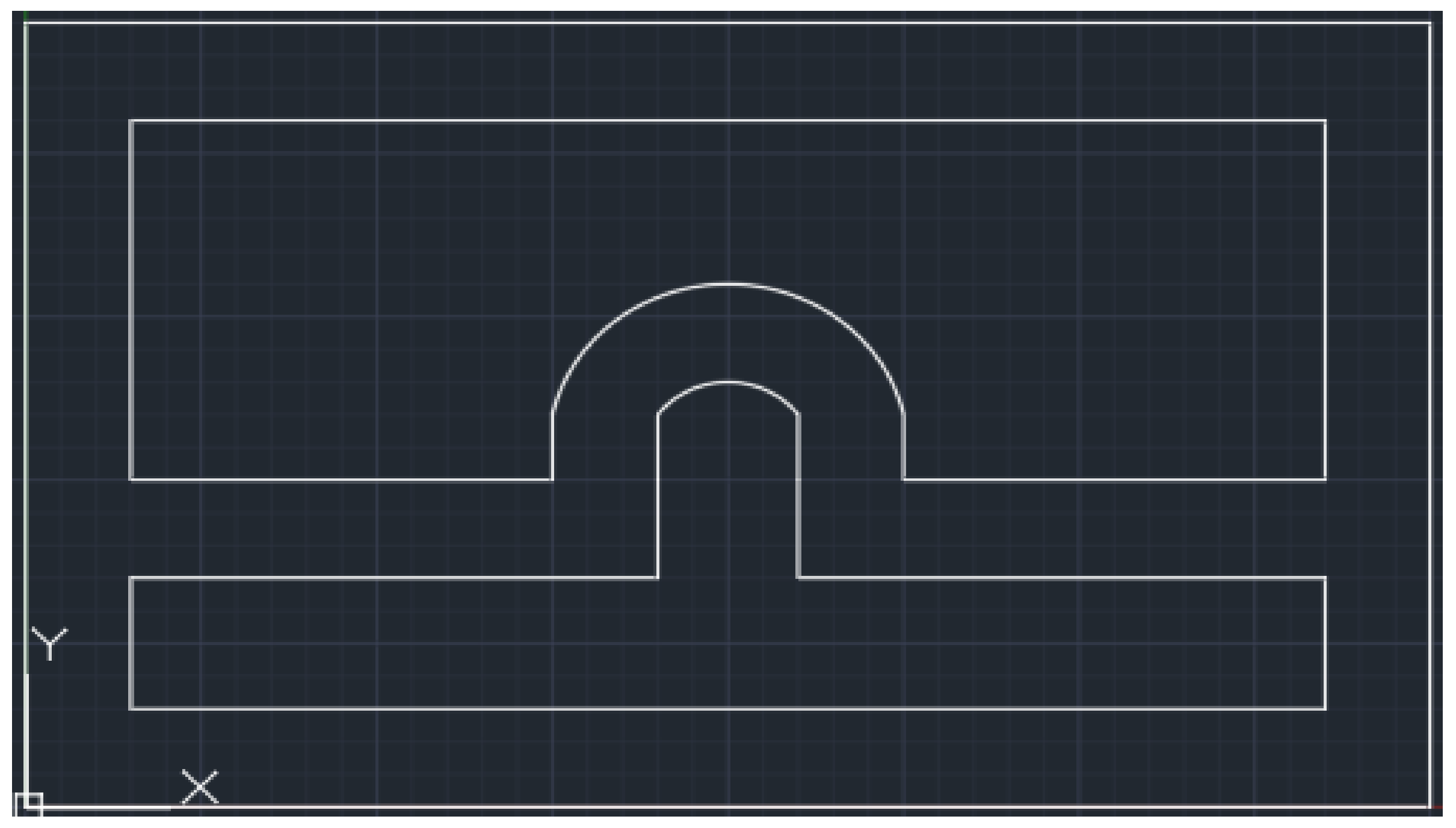
Figure 1. ICON Printer [19]. Reprinted with permission from Ref. [19]. 2022, ICON.
Buildings 13 00106 g001
Figure 2. Drawing Mimicking ICON wall configuration [20].
Buildings 13 00106 g002
Figure 3. Chicon House [22]. Reprinted with permission from Ref. [22]. 2018, ICON.
Buildings 13 00106 g003
Figure 4. Drawing Mimicking COBOD wall configuration [25].
Buildings 13 00106 g004
Figure 5. PERI’s completed apartment building in Germany [27]. Reprinted with permission from Ref. [27]. 2021, Jarett Gross.
Buildings 13 00106 g005
Figure 6. Black Buffalo gantry printer [4]. Reprinted with permission from Ref. [4]. 2022, Black Buffalo 3D.
Buildings 13 00106 g006
Figure 7. Black Buffalo wall configuration options [28].
Buildings 13 00106 g007
Figure 9. WASP 3D printer with insulation inside printed walls [10]. Reprinted with permission from Ref. [10]. 2018, WASP.
Buildings 13 00106 g009
Figure 10. Model Mimicking typical WASP 3D-printed cob design [33].
Buildings 13 00106 g010
Figure 11. WASP 3D-printed Gaia project [10]. Reprinted with permission from Ref. [10]. 2018, WASP.
Buildings 13 00106 g011
Figure 12. SQ4D arcs printer [35]. Reprinted with permission from Ref. [35]. 2021, Jarett Gross.
Buildings 13 00106 g012
Figure 13. SQ4D Typica wall configuration [8].
Buildings 13 00106 g013
Figure 14. Apis Cor robotic arm printer [40]. Reprinted with permission from Ref. [40]. 2021, Jarett Gross.
Buildings 13 00106 g014
Figure 15. Apis Cor wall configuration [43].
Buildings 13 00106 g015
Figure 16. Apis Cor completed building in Dubai [40]. Reprinted with permission from Ref. [40]. 2021, Jarett Gross.
Buildings 13 00106 g016
Figure 17. CyBe Printer on “Crawler System” [47]. Reprinted with permission from Ref. [47]. 2022, CyBe.
Buildings 13 00106 g017
Figure 18. CyBe completed Dubai laboratory [50]. Reprinted with permission from Ref. [50]. 2022, CyBe.
Buildings 13 00106 g018
Table 1. COBOD Mortar Mix Material Table [24]. Adopted from [24]. Table was recreated with rounded numbers and unit conversions from original.
MaterialQuantity (kg (lb))Price (USD)Percentages by Weight
Cement6100 (13,448)1515.4532%
0–2 mm (dia.) sand3500 (7716)87.1618%
0–4 mm (dia.) gravel3500 (7716)92.6018%
0–4 mm (side dimension) recycled roof tiles4400 (9700)76.2623%
Water1700 (3748)8.729%
Glonium sky 63140 (88)28.33~0%
Crackstop fibers20 (44)151.44~0%
Total19,260 (42,460)1959.96100%
Disclaimer/Publisher’s Note: The statements, opinions and data contained in all publications are solely those of the individual author(s) and contributor(s) and not of MDPI and/or the editor(s). MDPI and/or the editor(s) disclaim responsibility for any injury to people or property resulting from any ideas, methods, instructions or products referred to in the content.