Abstract
Metallic yielding dampers are damaged early before the main frame during earthquakes and take over the damage of the main frame. Under the assumption of the main frame elasticity, both maximum and residual deformation are expected to be reduced. However, the main frame may be damaged, and the assumption of the main frame elasticity may not hold under major earthquakes. However, large deformable elastic plates have larger yielding deformation than standard steel core plates of the damper and can be used as braces to reduce the seismic response of buildings. This study presents a simple definition of design variables for a topology optimization problem involving large deformable elastic plates with rectangular shapes. As bi-objective functions, yielding deformation and yielding force capacity maximization were used. The optimization results were compared with the findings of a previous study. Finally, the efficacy of the braces was verified by experimental tensile tests. The obtained results are as follows. (1) A distinct trade-off relationship was obtained between tensile yielding deformation and tensile yielding load through muti-objective optimizations using the proposed formulation. (2) The Pareto fronts using the proposed formulation were almost identical to the findings of the previous study. (3) While the experimental test results of yielding tensile load are overestimated by the analysis results by the 10 mm rough grid elements, the test results almost correspond to reanalysis results with the 2.5 mm fine grid elements.
1. Introduction
Brace structures have been used in many steel buildings because they provide excellent stiffness and strength to buildings at a low cost [1]. However, there are possibilities that buckling will occur at an early stage during major earthquakes [1]. Therefore, several studies have been conducted to enhance the hysteresis properties of braces, including metallic yielding dampers [2,3,4,5,6], buckling restrained braces [7,8], non-compression braces [9,10], and hybrid damper braces [11]. There are also review papers on this area [12,13,14]. The above metallic yielding dampers are damaged early before the main frame during earthquakes and take over the damage of the main frame. Under the assumption of the main frame elasticity, both maximum and residual deformation are anticipated to be reduced. However, the main frame may be damaged, and the assumption of the main frame elasticity may not hold under major earthquakes.
We have studied large deformable elastic braces (LDEBs), which can realize elastic response even during major earthquakes. From our previous studies, the tensile testing showed a substantial deformable elastic performance of the bracing, and time history analyses revealed a reduction in story drift’s maximum and residual response [15]. LDEBs have been involved in the evaluation of optimum topologies on large deformable elastic plates (LDEPs) as steel core plates [16,17].
Intermediate types between metallic yielding dampers and LDEBs can achieve various yield strengths, yield displacements, and energy dissipation capacities. We can develop the hybrid types with metallic yielding damper, LDEBs, and the intermediate types. Since these mechanisms are essentially different, the hybrid type is expected to achieve both residual deformation reduction and maximum response reduction synergistically. By installing the LDEBs with different elastic limits, we can develop a resilient function against multi-stage unexpected seismic motion levels.
There are few studies on optimum topologies of LDEBs and optimum structures with LDEBs and the intermediate and hybrid types, while there are several studies on optimization with metallic yielding dampers [18,19]. This study proposes a formulation for optimizing the topology of LDEPs with rectangular shapes. A four-column method is presented as a new topology formulation. In the formulation, the design variables become simpler than those in Ref. [17]. One of the multi-objective optimization methods, NSGA-II, proposed by Deb et al. [20,21] solves the optimization problem by maximizing the tensile yielding load and tensile yielding deformation. Furthermore, the trade-off relationship between the yielding load and the yielding deformation of LDEBs is explored using the Pareto solutions and compared with the previous studies. Finally, the optimization results are compared with experimental tensile tests. The study aims to present possible combinations of yield strength and yield deformation, including LDEBs and their intermediate types. This study is useful as a foundational resource for clarifying the method and characteristics of the optimum solution for determining the stiffness and yield strength of LDEBs and their intermediate and hybrid types.
2. Features of LDEPs and LDEBs
As described above, LDEPs are soft steel plates formed by laser cutting that show elastic behavior even if a large deformation occurs due to a major earthquake [1,15,16,17]. There is a study on folded braces by Hada et al. [22] as an earlier investigation into braces that aimed to increase the elastic limit. However, the elastic limit of the target brace was set to 1/200 of the story drift angle. The study by Hada et al. differs from our study in terms of the composition and manufacturing method. In this study, it is assumed that an LDEP is sandwiched by steel channels and bolts as shown in Figure 1 to prevent buckling of the plate and to function effectively as an LDEB. Since a building frame with LDEPs as braces exerts an elastic restoring force even after the beam–column plasticization in a major earthquake, it is expected that the response of maximum deformation and residual deformation will be reduced. According to the seismic response analysis of the portal frame [15], even with the addition of large deformation elastic knee braces of axial stiffness of only 500 N/mm, a maximum response reduction of around 20% and an extreme reduction in large residual deformation response were confirmed. This study investigates the relationship between yielding load and yielding deformation that can be realized by morphological creation from a 9 mm thick steel plate using a multi-objective optimization method.
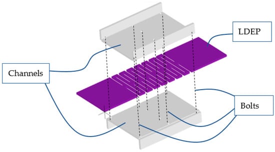
Figure 1.
An LDEP sandwiched by steel channels and bolts.
3. Formulations
3.1. Topology Formulation of LDEPs with Rough Rectangular Element Shapes
Here, to reduce computational requirements for optimization, plates are divided into rough rectangular element shapes and optimized with topological patterns based on rectangular shapes.
The following two approaches are introduced for the topology formulation of LDEPs.
3.2. Inverse Fourier Formulation
There is a common method of topology optimization of continuum structures that involves expression as solid or void, and research has been conducted. In early studies, many challenges were identified, including the checkerboard patterns in which solid and void occur alternately [23], and different computational enhancements [24] were proposed. To prevent the checkerboard patterns, the topology formulation uses a function comparable to the inverse Fourier transform, as shown in Appendix A.
3.3. Four-Column Formulation
To obtain optimal solutions efficiently and simply, consider the following topology representation named the four-column formulation.
[Fourcolumn formulation]
If MOD(i/4) = 0, then zij = 1 (j ≤ x1 or j ≥ ny − 2 − x1); zij = 0 (ny − 2 − x1 > j > x1).
If MOD(i/4) = 1, then zij = 1.
If MOD(i/4) = 2, then zij = 0 (j ≤ x2 or j ≥ ny − 2 − x2); zij = 1 (ny − 2 − x2 > j > x2).
If MOD(i/4) = 3, then zij = 1;
x1, x2: integer design variables;
i: column number of finite element (i,j) (i = 0, 1, 2, … nx − 1);
j: row number of finite element (i,j) (j = 0, 1, 2, … ny − 1);
MOD(i/4): the remainder of i divided by 4;
zij: zij = 1 represents that element (i,j) is solid, and zij = 0 represents that element (i,j) is void.
3.4. Multi-Objective Optimization Problem Based on Four-Column Formulation
In the past consideration of topology optimization of LDEPs that maximize yielding deformation as a single objective function, the trade-off relationship between yielding deformation and yielding load was identified. However, few studies have investigated this tendency. Here, tensile yielding deformation, Uy, and tensile yielding load, Py, are used as bi-objective functions, and the following optimization problems are specified for the four-column formulation.
Find integer design variables, x1 and x2, which maximize
where
U is the maximum tensile displacement in all nodes;
P is the total tensile load in all nodes;
σ0 is the tensile yield strength of steel plate material;
σMmax is the maximum value of von Mises stress in all nodes.
4. Numerical Results
This section describes the results of the morphological creation of LDEPs for bracing structures. A plate is prepared, in which the total lengths in the x-direction and y-direction are fixed to 660 mm and 200 mm, respectively, as shown in Figure 2. For linear elastic analysis by finite element method (FEM) software, LISA [25], the plate is divided into a total of 1320 (66 × 20, 10 mm grid) elements. The plane stress conditioned elements with quadratic nodes, Young’s modulus of 205,000 (MPa), Poisson’s ratio of 0.3, and plate thickness of 9 mm are used. Table 1 shows non-dominated final solutions (σ0 = 325 MPa) by multi-objective optimization (NSGA-II) [20,21] based on the four-column formulation. Due to the small design region, only 500 function evaluations (50 individuals) converged to constant solutions. In the process of optimization, the nodes surrounded by void elements and the void elements themselves are completely removed from the computer program, and the node numbers and element numbers are automatically revised. For comparison, single optimum solutions by strain energy maximization using the inverse Fourier formulation (Appendix A) are also shown in Table 2. Due to a very large design region, 15,000 function evaluations (50 individuals) were needed to obtain the results. Figure 3 shows the distinct trade-off relationship between tensile yielding deformation and tensile yielding load for the four-column formulation. Additionally, the figure shows that Pareto fronts of the two formulations almost correspond to each other. Figure 3 also shows topology patterns for several solutions. The yellow color represents a solid, while the brown represents a void.
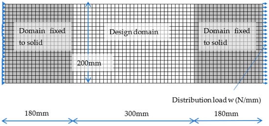
Figure 2.
Design domain.

Table 1.
Non-dominated final solutions by NSGA-II with the four-column formulation.
Table 2.
Single optimum solutions by strain energy maximization using inverse Fourier formulation (Appendix A).
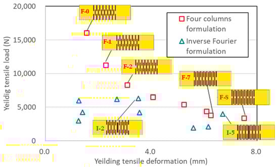
Figure 3.
Relationship between tensile yielding deformation and tensile yielding load.
5. Experimental Tensile Tests of the Two Optimized Specimens
The two optimized specimens, F-7 and F-8, shown in Figure 4 and Figure 5, were laser cut from 9 mm thick steel plates (SM490) using a laser cutting machine. According to a mill sheet, the yield strength of the steel plates is 407 MPa. Experimental tensile tests were performed on the specimens by a universal testing machine at Shimane University, as shown in Scheme 1. Figure 6 and Figure 7 show the relationship between tensile deformation and load of specimens with the computational results from Table 1. As shown in blue circles in Figure 6 and Figure 7, there exists around 400 (N) of initial load. The reason is that from the initial stage to exceeding around 1000 (N), we used the total weight of ourselves to apply gripping force not only to handle B but also to handle A in Scheme 1. The test load was applied to the limit of displacement transducers and then unloaded. The computational results from Table 1 do not correspond to the test results because of rough element division. However, the reanalysis results by 2.5 mm grid elements with σ0 = 407 MPa almost correspond to the test results. As a result, a 10 mm rough grid element overestimates the yielding load and requires a reanalysis of the 2.5 mm fine grid elements after optimization by the 10 mm grid elements. Figure 8 and Figure 9 show the von Mises stress distribution for F-7 and F-8 using finite element analysis with 2.5 mm grid elements. It is observed that relatively high bending stress is widely distributed.
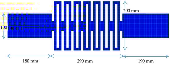
Figure 4.
Dimensions of test specimen F-7 (10 mm grids).
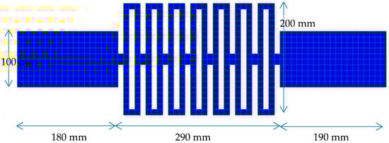
Figure 5.
Dimensions of test specimen F-8 (10 mm grids).
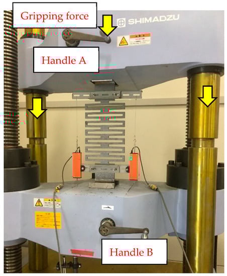
Scheme 1.
Tensile experiments by universal testing machine (F-7, at around 4400 N of tensile load).
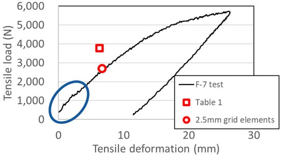
Figure 6.
Relationship between tensile deformation and tensile load for F-7 specimen.
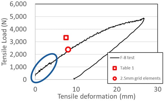
Figure 7.
Relationship between tensile deformation and tensile load for F-8 specimen.
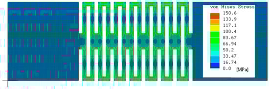
Figure 8.
Von Mises stress distribution by FEM analysis with 2.5 mm grid elements (F-7).
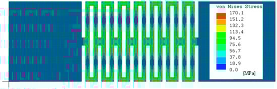
Figure 9.
Von Mises stress distribution by FEM analysis with 2.5 mm grid elements (F-8).
6. Relationship between Yielding Deformation and Yielding Load of LDEPs
Since the tensile yielding load is overestimated by the 10 mm rough grid elements according to experimental tests, a reanalysis with the 2.5 mm fine grid elements is required after rough optimization. Table 3 shows the reanalysis results with the 2.5 mm grid elements for the solutions in Table 1. Here, yield strength of materials is 325 (MPa). Figure 10 shows the relationship between tensile yielding deformation and tensile yielding load for the reanalysis results. One can select the bracing devices for structural design from a variety of LDEPs also containing conventional steel dampers.
Table 3.
Reanalysis results with the 2.5 mm grid elements for the solutions in Table 1.
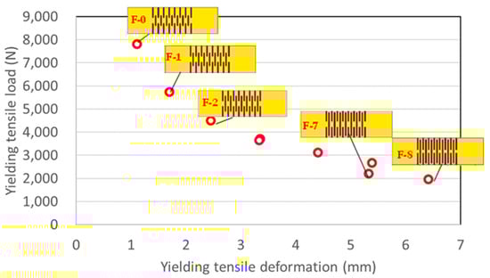
Figure 10.
Relationship between tensile yielding deformation and tensile yielding load (2.5 mm grid elements).
7. Conclusions
This study has proposed a formulation, that is, the four-column method, for topology optimization of LDEPs with rectangular shapes. The multi-objective optimization problems that maximized tensile yielding load and tensile yielding deformation were solved by the multi-objective genetic algorithm NSGA-II. In addition, the trade-off relationship between yielding load and yielding deformation of LDEPs has been investigated and compared using the obtained Pareto solutions. Finally, experimental tensile tests were performed. Concluding remarks are as follows.
- (1)
- A distinct trade-off relationship was obtained between tensile yielding deformation and tensile yielding load through muti-objective optimizations using the four-column formulation.
- (2)
- The Pareto fronts using the inverse Fourier formulation and the four-column formulation are almost identical based on optimum computation.
- (3)
- While the test results of yielding tensile load are overestimated by the 10 mm rough grid elements, the test results almost correspond to reanalysis results with the 2.5 mm fine grid elements.
Author Contributions
Conceptualization, K.S.; methodology, K.S.; formal analysis, K.K. and K.S.; experimental tests, S.K., K.K., J.T., T.U. and K.S.; writing—original draft preparation, K.K. and K.S.; writing—review and editing, S.K.; supervision, K.S. and S.K. All authors have read and agreed to the published version of the manuscript.
Funding
This research was funded by the Japan Iron and Steel Federation.
Institutional Review Board Statement
Not applicable.
Informed Consent Statement
Not applicable.
Data Availability Statement
Not applicable.
Conflicts of Interest
The authors declare no conflict of interest.
Appendix A. (Revised from [16,17])
A topology optimization problem for a plane stress two-dimensional plate is considered. A function similar to the inverse Fourier transform function is defined to represent the topological patterns of the plate as follows.
where u = −NFX, …, −3, −2, −1, 1, 2, 3, …, NFX, v = −NFY, …, −3, −2, −1, 1, 2, 3, …, NFY, i represents an imaginary unit, e represents the Naperian base, and au,v and bu,v are real-valued parameters to be computed in the optimization process, which are greater than –1 and less than 1. xk and yk represent x- and y-coordinates of the center of the element k. In this study, NFX = 2 and NFY = 2 are adopted.
Since F should be a real function, the following complex conjugate conditions can be used.
Each element is distinguished as either a solid or a void according to the value of F. If the value of F corresponding to the element k satisfies the following equation, the element k is a solid, otherwise it is a void.
where Fmax and Fmin represent the maximum and minimum values of F, respectively, over all the elements. β (−1 ≤ β ≤ 1) represents a parameter to be computed in the optimization process.
The topology optimization problem of LDEPs can be formulated as follows.
Find au,v, bu,v, and β which minimize
where E1 represents total strain energy over all the solid elements, S1max represents the maximum value of von Mises stress over all the Gaussian integration points of all the solid elements, and S0max represents that of all the void elements. In this study, PE = −1 and PS = 4 are adopted.
References
- Kishizoe, M.; Sawada, K. Seismic responses of steel frames with large deformable elastic devises as braces. Steel Constr. Eng. 2020, 27, 53–59. (In Japanese) [Google Scholar]
- Skinner, R.I.; Kelly, J.M.; Heine, A.J. Hysteretic dampers for earthquake-resistant structures. Earthq. Eng. Struct. Dyn. 1974, 3, 287–296. [Google Scholar] [CrossRef]
- Whittaker, A.S.; Bertero, V.V.; Thompson, C.L.; Alonso, L.J. Seismic Testing of Steel Plate Energy Dissipation Devices. Earthq. Spectra 1991, 7, 563–604. [Google Scholar] [CrossRef]
- Tamai, H.; Kondoh, K.; Hanai, M. On Low-Cycle Fatigue Characteristics of Hysteretic Damper and Its Fatigue Life Prediction under Severe Earthquake Ground Motion. J. Struct. Constr. Eng. (Trans. AIJ) 1994, 59, 141–150. (In Japanese) [Google Scholar] [CrossRef]
- Chan, R.; Albermani, F. Experimental study of steel slit damper for passive energy dissipation. Eng. Struct. 2008, 30, 1058–1066. [Google Scholar] [CrossRef]
- Bagheri, S.; Barghian, M.; Saieri, F.; Farzinfar, A. U-shaped metallic-yielding damper in building structures: Seismic behavior and comparison with a friction damper. Structures 2015, 3, 163–171. [Google Scholar] [CrossRef]
- Black, C.J.; Makris, N.; Aiken, I.D. Component Testing, Seismic Evaluation and Characterization of Buckling-Restrained Braces. J. Struct. Eng. 2004, 130, 880–894. [Google Scholar] [CrossRef]
- Hoveidae, N.; Rafezy, B. Overall buckling behavior of all-steel buckling restrained braces. J. Constr. Steel Res. 2012, 79, 151–158. [Google Scholar] [CrossRef]
- Tamai, H.; Takamatsu, T. Cyclic loading tests on a non-compression brace considering performance-based seismic design. J. Constr. Steel Res. 2005, 61, 1301–1317. [Google Scholar] [CrossRef]
- Komatsu, S.; Takamatsu, T.; Tamai, H.; Yamanishi, T. Study on Seismic Response Reduction of SingleStory Anti-Symmetric Z-Type NC Braced Frame. J. Struct. Constr. Eng. (Trans. AIJ) 2014, 79, 1677–1685. (In Japanese) [Google Scholar] [CrossRef]
- Murakami, Y.; Noshi, K.; Fujita, K.; Tsuji, M.; Takewaki, I. Simultaneous optimal damper placement using oil, hysteretic and inertial mass dampers. Earthq. Struct. 2013, 5, 261–276. [Google Scholar] [CrossRef]
- Symans, M.D.; Constantinou, M.C. Semi-active control systems for seismic protection of structures: A state-of-the-art review. Eng. Struct. 1999, 21, 469–487. [Google Scholar] [CrossRef]
- Parulekar, Y.M.; Reddy, G.R. Passive response control systems for seismic response reduction: A state-of-the-art review. Int. J. Struct. Stab. Dyn. 2009, 9, 151–177. [Google Scholar] [CrossRef]
- Nakamura, Y.; Okada, K. Review on seismic isolation and response control methods of buildings in Japan. Geoenviro. Disasters 2019, 6, 2. [Google Scholar] [CrossRef]
- Nakamura, K.; Nishida, G.; Sawada, K. Seismic response of portal steel frames with large deformable elastic members. Proc. Constr. Steel 2016, 24, 476–482. (In Japanese) [Google Scholar]
- Sawada, K. Seismic response analyses of rc portal frames with large deformable elastic braces. Int. J. Comput. Methods Exp. Meas. 2017, 6, 880–886. [Google Scholar] [CrossRef]
- Sawada, K. Topology optimization of large deformable elastic plates. J. Struct. Constr. Eng. 2020, 85, 683–692. (In Japanese) [Google Scholar] [CrossRef]
- Inoue, K.; Kuwahara, S. Optimum strength ratio of hysteretic damper. Earthq. Eng. Struct. Dyn. 1998, 27, 577–588. [Google Scholar] [CrossRef]
- Kim, Y.-C.; Mortazavi, S.J.; Farzampour, A.; Hu, J.-W.; Mansouri, I.; Awoyera, P.O. Optimization of the Curved Metal Damper to Improve Structural Energy Dissipation Capacity. Buildings 2022, 12, 67. [Google Scholar] [CrossRef]
- Getting Started—Platypus Documentation. Available online: https://platypus.readthedocs.io/en/latest/getting-started.html (accessed on 10 January 2022).
- Deb, K.; Pratap, A.; Agarwal, S.; Meyarivan, T.A. A fast and elitist multiobjective genetic algorithm: NSGA-II. IEEE Trans. Evol. Comput. 2002, 6, 182–197. [Google Scholar] [CrossRef]
- Hada, M.; Takeuchi, K.; Kitajima, K.; Nakanishi, M. Study on structural characteristics of folded brace Investigation of increase of axial yield displacement and buckling restraint effect. J. Struct. Constr. Eng. (Trans. AIJ) 2020, 85, 373–381. (In Japanese) [Google Scholar] [CrossRef]
- Chapman, C.D.; Saitou, K.; Jakiela, M.J. Genetic algorithms as an approach to configuration and topology design. J. Mech. Des. 1994, 116, 1005–1012. [Google Scholar] [CrossRef] [Green Version]
- Fujii, D.; Kikuchi, N. Improvement of numerical instabilities in topology optimization using the SLP method. Struct. Multidiscip. Optim. 2000, 19, 113–121. [Google Scholar] [CrossRef]
- LISA-Free/Affordable Finite Element Analysis Software. Available online: https://lisafea.com/ (accessed on 10 January 2022).
Publisher’s Note: MDPI stays neutral with regard to jurisdictional claims in published maps and institutional affiliations. |
© 2022 by the authors. Licensee MDPI, Basel, Switzerland. This article is an open access article distributed under the terms and conditions of the Creative Commons Attribution (CC BY) license (https://creativecommons.org/licenses/by/4.0/).