1. Introduction
Formwork design is an important part of the building construction process and must be engineered to withstand the maximum applied loads and maintain structural integrity [
1]. One way that the design of formwork can be optimized is by creating a proposed formwork system using building information modeling (BIM) [
2,
3]. Hyun et al. [
2] conducted a case study on a hospital project in Seoul using BIM automation for formwork design—they stated, “The proposed formwork system automatically produced formwork designs taking various considerations such as concrete pressure, bending, deflection, and horizontal shearing while utilizing a BIM model to estimate the cost and duration information given for each variation.” This proves that BIM automation can be used to optimize the formwork design process and generate construction drawings to be reviewed and approved by the engineers. Another example of how technology can be utilized to optimize the design of formwork is a study of Hanna and Senouci [
4], which was conducted on the cost-effective, durable slab form design. Their study revealed that the optimal design method in respect of formwork components and their spacings produces cost savings because the total cost of the slab form depends on the material and labor costs. They found that a reduction in joist spacing by 0.1 m (4 in) results in a significant formwork cost savings and the joist spacing of 0.4 m (16 in) yields the minimum slab form cost. This is because reducing the joist spacing decreased both the number of stringers and wood shores.
The failure of formwork can occur due to several reasons, such as excessive loads, premature removal of shores or forms, inadequate design, and human errors resulting from haste and lack of knowledge or interest [
5]. There are many instances where a formwork system failed and collapsed due to improper design regarding the type of materials used or the size and durability of the materials used, and it is important to analyze these occurrences to determine the causes of the failure. A study conducted by Autengruber et al. [
6] revealed that the exposure to moisture can be detrimental to the structural integrity of the wooden formwork system—they reported that the wet beam undergoes significant physical changes due to the elevated moisture level, resulting in moisture-induced deformations in the cross section within the flange zones that seriously affect the resistance of formwork to the external loads. While the moisture content within the wood may be a common cause for failure in a wooden formwork system, the study of Li and Yin [
7] provided an interesting comparison by measuring the performance of permanent textile reinforced concrete (TRC) forms and determining the mode of failure. Li and Yin [
7] stated, “When the length of the TRC permanent formwork is long, the textile breaks due to the bond strength between the textile and the matrix being greater than the ultimate tensile strength of the textile.” They also found that the interface adhesion no longer continues to increase when the length of the formwork is greater than 150 mm.
After the formwork system has been designed and installed correctly to maximize structural integrity, the next step of construction is to pour the concrete. Then the formwork is removed once the concrete has set and gained adequate strength to bear self-weight and construction loads. Safety precautions must be taken while stripping the formwork and exposing the hardening concrete. Jha and Sinha [
8] have noted, “Stripping formwork can be one of the most hazardous phases of in-situ concrete construction. While falling objects are the primary hazard, there may also be fall hazards as a result of floor collapse and manual tasks hazards from a person working in awkward postures, repetitive handling of materials and limited task variety.” They further stated, “Climbing partially stripped formwork is not only hazardous but unnecessary. Safe access such as rolling scaffolds or powered elevating work platforms should be provided for stripping formwork at elevated locations.” Once the formwork is removed, the next hazard can be imposed by the hardening concrete which has not reached its full strength yet. The Editors of Fine Homebuilding [
9] asserted, “Concrete doesn’t reach its full compressive strength for 28 days or so, but 5 days to 7 days is usually sufficient curing time for the concrete walls to withstand backfill pressure. Still, it’s always a good precaution to brace the inside of any green walls that are long and straight before backfilling against them.” It suggests that the hardening concrete could fail if it is overloaded beyond its capacity.
A very crucial component in reinforced concrete buildings is the steel reinforcing bars that are placed throughout to enhance the structural capacity and performance of the structure; however, one of the main concerns with steel rebars is corrosion [
10,
11]. The phenomenon of steel rebar corrosion within a reinforced concrete building is partly due to the geographic location of the building and its proximity to the ocean which can result in high precipitation and a crystalline deposit of salts known as efflorescence. Castañeda et al. [
12] reported that efflorescence was the main cause of steel rebar corrosion in the reinforced concrete structure at 170 m of distance from the sea in Havana City. Reinforced concrete corrosion comes with a serious detrimental impact to the longevity of concrete buildings in coastal areas with high precipitation as the expansion force created by rust occurring within the concrete can cause cracking and failure. According to Chen et al. [
13], the tensile strain on the concrete surface and the compressive strain on the inner wall of the steel pipe reinforcement continue to increase prior to the appearance of cracks due to the expansion force caused by the corrosion of reinforcement.
The interfacial bond between rebar and concrete and the factors that affect this bond strength are also vital regarding the structural integrity and service life of concrete buildings. Concrete strength and rebar diameter are two of the crucial factors that influence the interfacial bond strength [
14]. Alharbi et al. [
15] stated, “The change of concrete strength from 35 MPa to 20 MPa yielded about 39% reduction in bond strength.” They also reported, “Steel rebar diameter yielded inverse proportion to bond strength whereas, replacing 16 mm rebar diameter with 12 mm rebar diameter resulted in about 20% increase in bond strength.” Another major factor that influences the interfacial bond between rebar and concrete is the method used to compact the concrete after pouring; the bond strength has been recorded as higher in the case of self-compacting concrete (SCC) in comparison to normally vibrated concrete (NVC) [
16]. The study conducted by Kanellopoulos et al. [
17] uncovered, “The sensitivity of mixtures to vibration should be seriously considered in practice. Although high slump mixtures in shallow specimens show a better degree of compaction and have improved mechanical properties, in deep specimens there is an increased likelihood of poor cohesion between concrete and reinforcement at the top of the element.” They stated that the nature of the interface between steel rebar and concrete depends on the viscosity and flowability or workability of concrete mixtures. The comparison drawn between SCC and NVC in terms of performance regarding mechanical properties and interfacial bond certainly sparks an interesting debate on which concrete a contractor may choose when pouring structural concrete elements.
The authors conducted this study for practical viewpoints on concrete forming, reinforcing, and pouring, which are three fundamental stages of modern construction. If building codes and guidelines as well as construction specifications and drawings are not followed meticulously, the failure of the buildings would occur for many reasons. This research aims to explore the insights of industry professionals into concrete formwork design, rebar size and spacing, causes of formwork failure and rebar corrosion, functionality of concrete strength, factors that influence the bond strength between rebar and concrete, and safe work practices for construction. Globally, the failure of the buildings can occur during and after construction if concrete and rebars are not designed correctly. In addition, faulty formwork design and inadequate construction practices (for instance, poor curing) may cause the failure of the buildings during the construction stage. These key points are discussed in
Section 4.2 and
Section 4.7 of this paper. Furthermore, failure generally can be controlled through proper designs of formwork, rebars and concrete mixture, and exact construction practices, for instance, using a suitable curing method during hardening of concrete elements. In the cases of failure, the retrofitting of the failed buildings is required. Depending on the type and extent of failure, patching can be used. In severe cases, the whole structural elements may need to be repoured. These key points are also discussed in
Section 4.2,
Section 4.6 and
Section 4.10 of this paper.
4. Results and Discussion
The interview results are presented and discussed in the following sub-sections, which have been created based on 10 interview questions. The sub-headings are consistent with the questions asked and the answers gathered from the interviews.
4.1. Complications while Installing Formwork and Resolution
The authors determined from the interviews that complications while placing formwork can be avoided by ensuring that everything is compliant to the specifications. All works must be completed according to the drawings and a paper trail must be created to show that the engineer’s instructions were followed appropriately.
A major complication that can arise when laying formwork and pouring a foundation in the cold-region countries with sub-normal temperatures is having frozen substratum beneath the concrete which causes differential settlement of the foundation. In such a situation, no construction tasks can take place on top of the foundation until it settles properly, and thermal equilibrium is reached. This raises a good point of view that it is not just about the type of material and the design of formwork which can have effects on the success of a formwork system, as it is also hinged directly on the surrounding environment. Dietsch and Tannert [
22] reported that about 46% of the damage cases of glued-laminated timber elements are related to moisture events. Autengruber et al. [
6] stated “When designing wooden beams used in formwork for concrete constructions, changing environmental conditions during loading as well as storing play a role.” This relates to the frozen substratum and highlights an excellent point that the design of the formwork and the type of wood used are very crucial when the formwork is exposed to moisture and other environmental implications.
In the case of long pours, the formwork contractor most often rushes to stay ahead of the rebar placement and pouring of concrete. As a result, mistakes in formwork may happen and therefore the quality of construction could be degraded. Such complications can be avoided by having a rebar inspector on the jobsite for immediate inspection so that the concrete can pour directly afterwards. This will also help manage and schedule the construction trades prudently so that there is no overlap, and the trades can stay constantly busy, contributing to higher productivity.
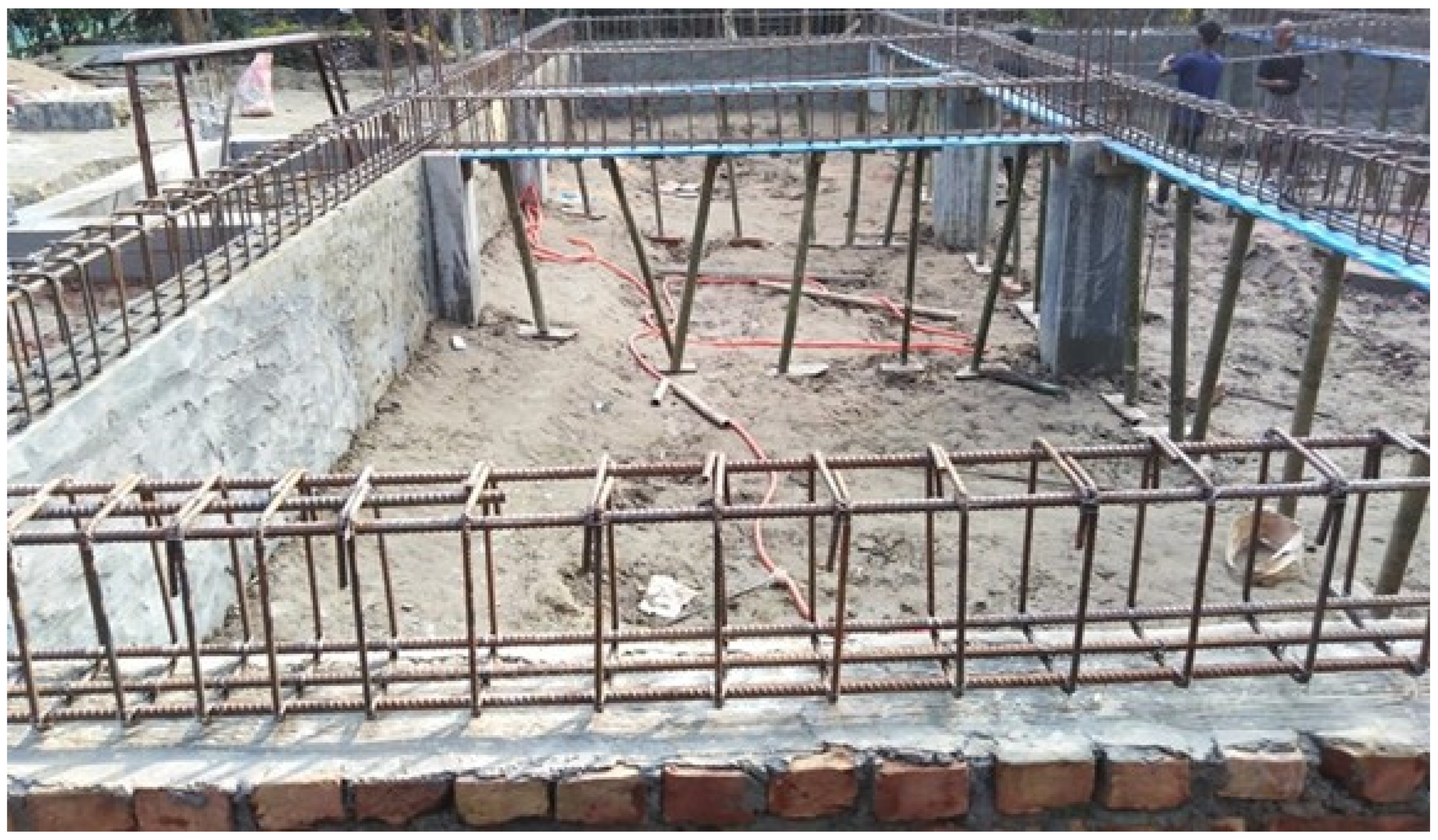
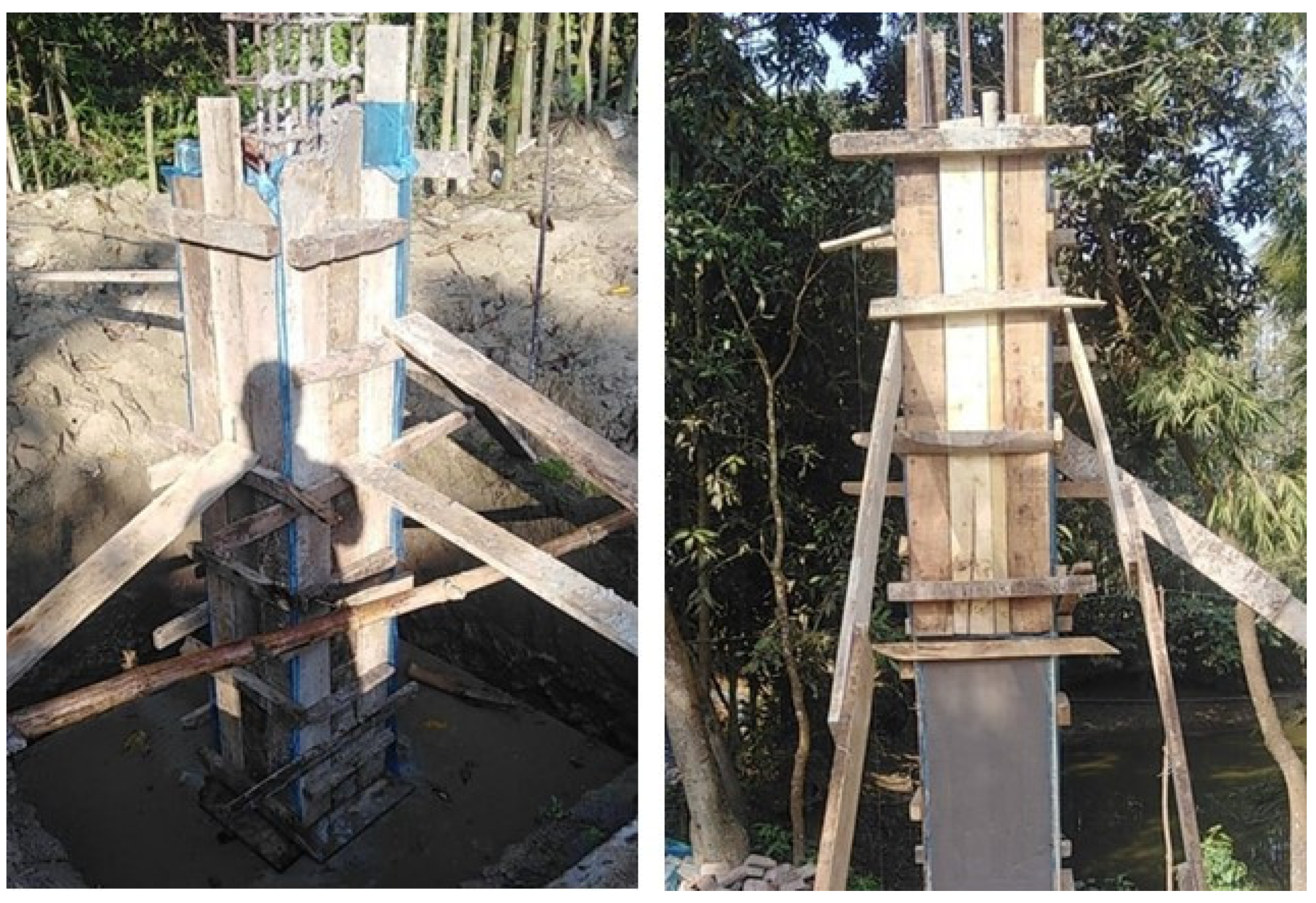
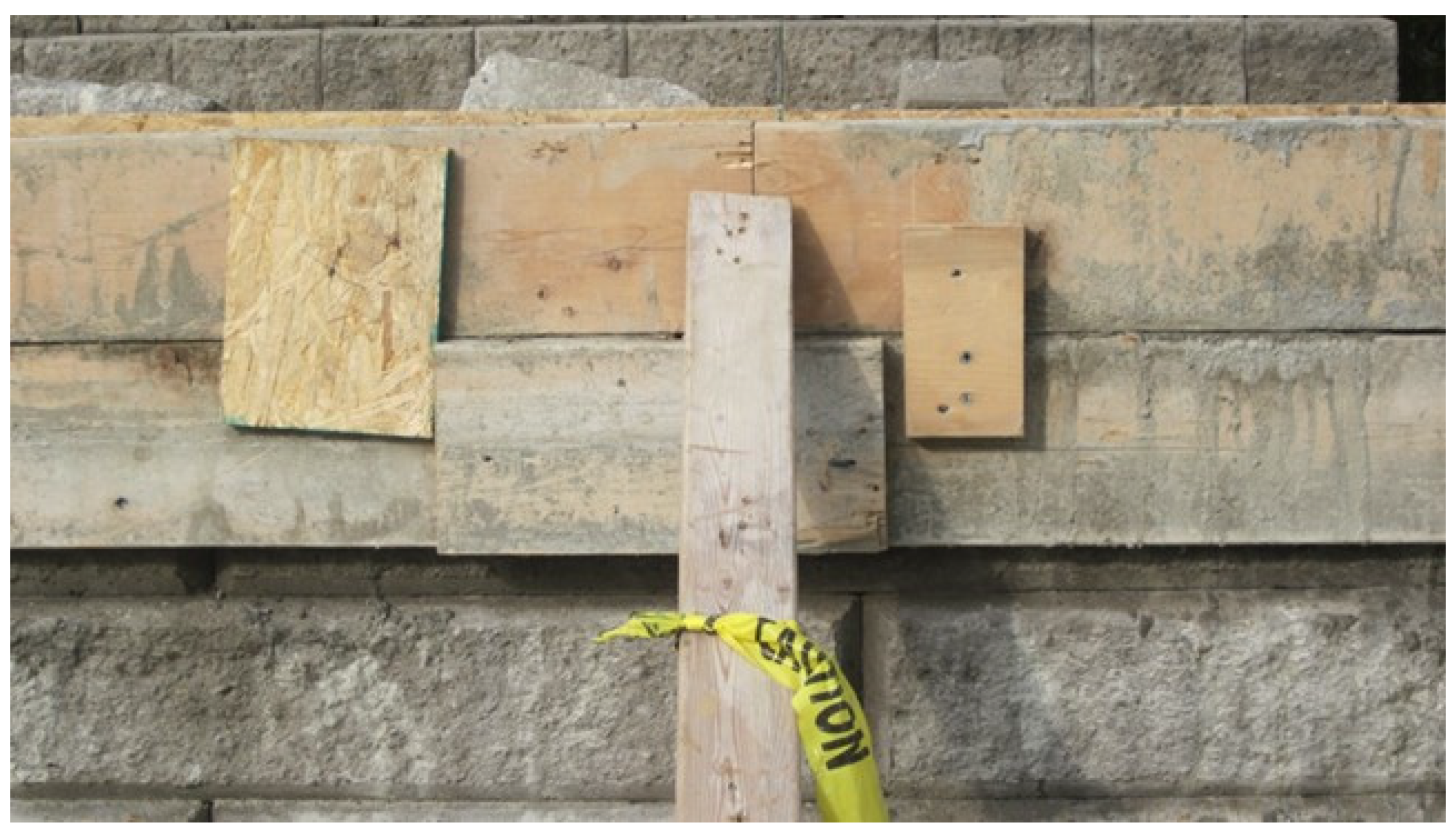
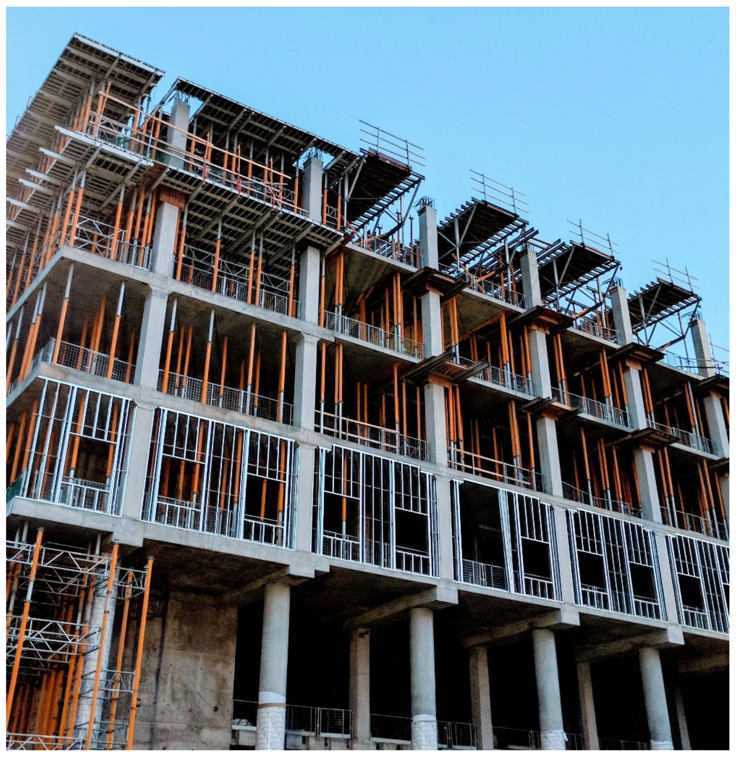
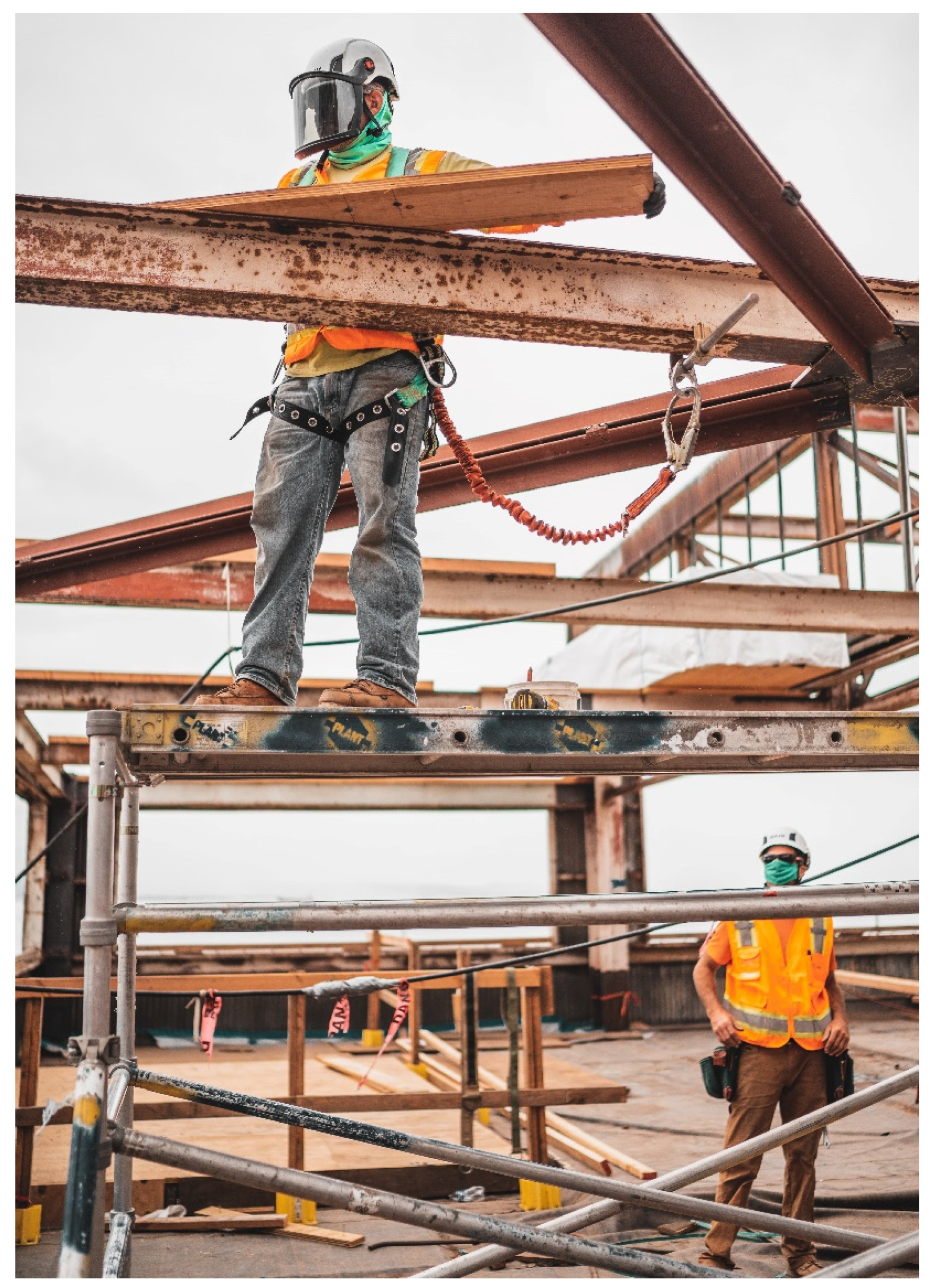
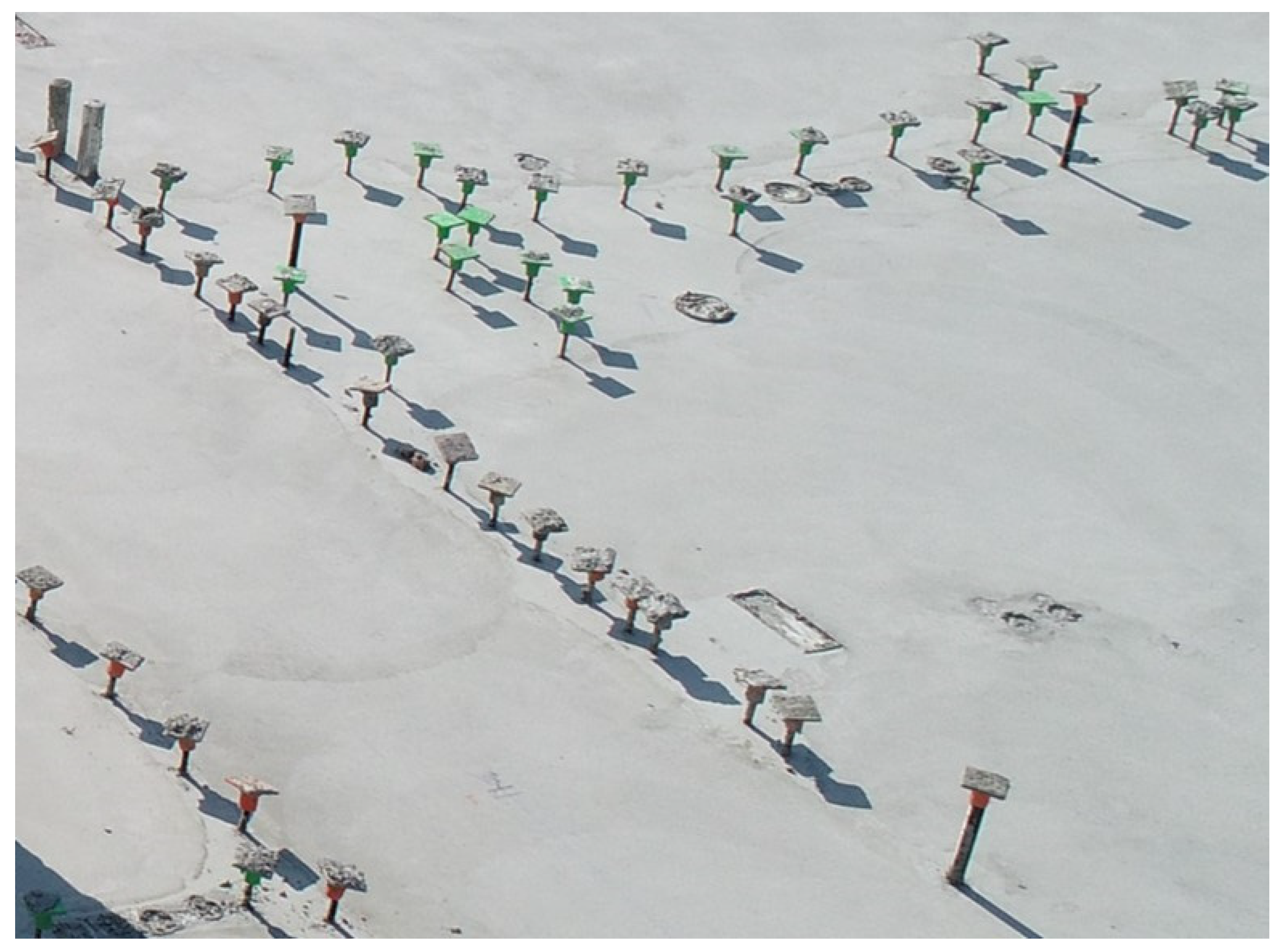
Among other issues, inadequate layout can occur while formwork is being placed. Such a mistake can lead to the elements being poured out of tolerance. When concrete does not stay within the tolerance, it can affect the trade works that follow concreting, such as structural steel connections, glazing, and interior finishes. The best work practices are to track each element which is poured on a jobsite using pre-pour and post-pour checklists covering the formwork layout and the pour to verify that the work is within the tolerance. To conclude, the importance of formwork structures is highlighted best by, “Concrete forms are engineered structures that are required to support loads composed of the fresh concrete, construction materials, equipment, workers, impact of various kinds, and sometimes wind. The forms must support all the applied loads without collapse or excessive deflection” [
4]. The authors see this quote as an accurate depiction and synopsis of the importance of formwork system in construction. It must be ensured that the formwork system is well-supported and stable, no matter whether it is shallow or deep and used for beam, column, or wall (refer to
Figure 1,
Figure 2 and
Figure 3).
4.2. Causes of Failures of Formwork and Hardening/Hardened Concrete
Formwork might fail if not designed correctly to withstand the pressure arising from the fresh concrete that has been poured. The interviewees revealed that the high pressure developing from concrete forming can cause the formwork system to explode and fail completely. Once concrete pouring starts, hydrostatic pressure is developed. This pressure increases with the depth of formwork. Consequently, the maximum pressure developed at the bottom of the formwork could separate the formwork sheeting unless braced properly from the outside. The situation can be worsened when vibration is applied to compact the concrete. The high pressure combined with vibration may cause an explosion, resulting in concrete flooding and injuries to construction laborers. Such an occurrence was experienced by one of the authors of this study in the case of stay-in-place formwork used for self-consolidating concrete, which can develop even more pressure due to its higher fluidity. This highlights the importance of having an engineered formwork system that is approved and suitable to withstand the live load of pouring concrete.
The formwork for concrete walls may fail due to incorrectly installed snap ties, which could pop under the pressure built up against the interior wall of the formwork system due to the concrete pouring. Snap ties are used to hold together the formwork sides for long concrete wall pours. Once these snap ties pop, it jeopardizes the structural integrity of the formwork system and can result in failure during concrete pouring.
The formwork system can fail if the band ties used to strap 4 × 4s in creating bulkheads for the formwork system break. In such a formwork failure, a concrete blow out occurs. In the cases of beams and hanging walls, the formwork system includes decking material to form the bottom. If the bottom material is not attached properly to the formwork system, failure can happen. When the decking material is simply butted against the two sides of the formwork system, once the weight of the concrete being poured is applied to the system, it creates a gap between the deck and the formwork, causing a blowout.
The formwork system must be designed to withstand the loading caused by the weights of concrete and rebars, as well as construction equipment and laborers; otherwise, failures will occur, and this will cause safety issues and schedule delays. Li and Yin [
7] investigated the failure modes of various TRC permanent formwork systems and determined that one of the main failure modes resulted due to increased loading. They observed that the textile continuously slipped in the matrix as the load continued to increase. This kind of failure mode suggests that the interface between the textile and the matrix in the TRC permanent formwork is a weak zone compared with other places susceptible to failure.
Hardening concrete will fail if it does not gain adequate strength to support the self-weight of structural elements and construction loads before removing the formwork. This implies that the failure of hardening concrete may occur if the formwork is removed too early, and the concrete has not been given enough time to gain structural integrity. Jha and Sinha [
8] said, “In no circumstances formworks should be removed until the concrete reaches strength of at least twice the stress to which concrete may be subjected at the time of striking”. It can be implemented only by knowing the strength of the concrete and the stress applied to it—the former must be greater than the latter to avoid the failure of structural elements.
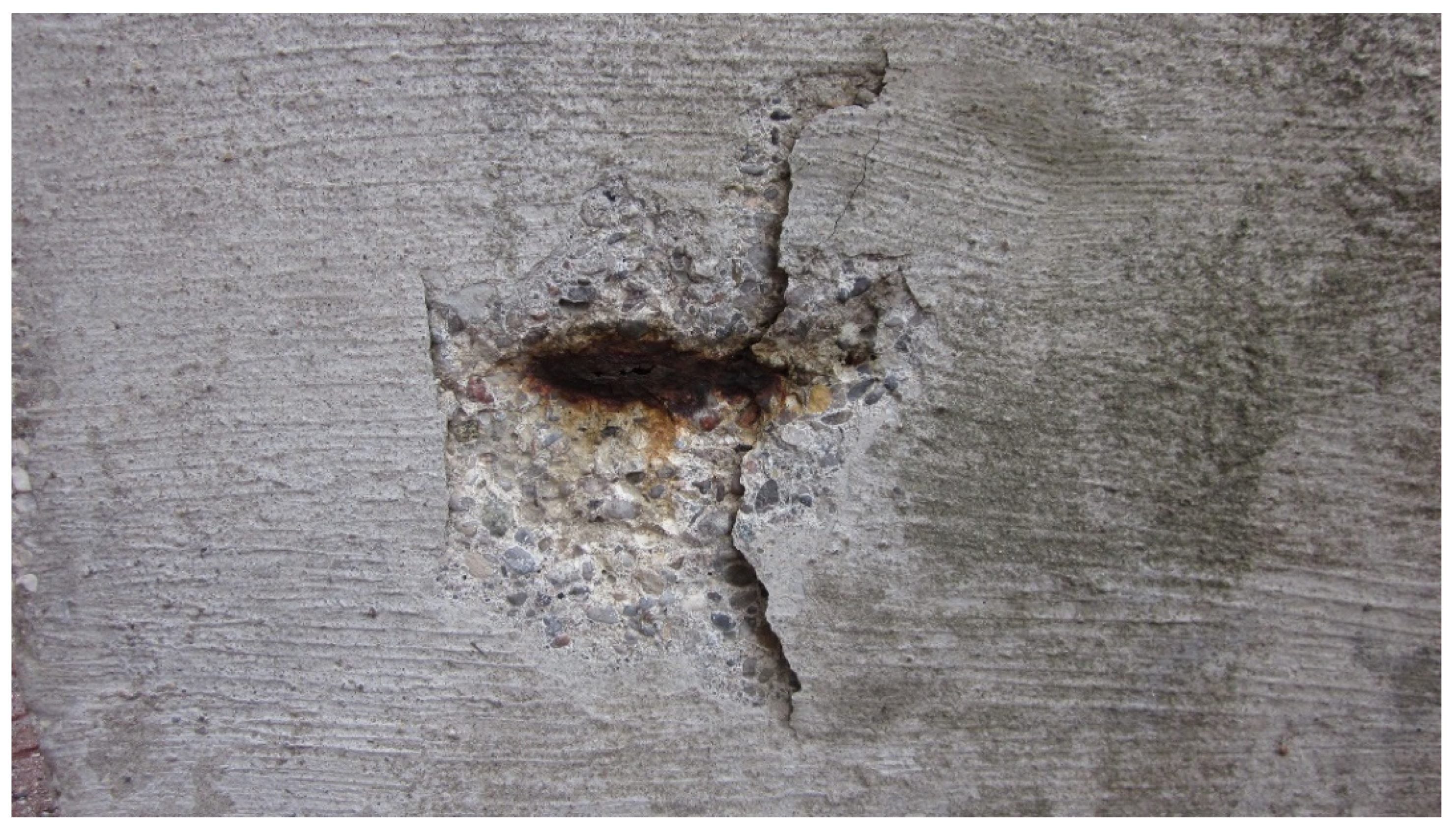
The failures of concrete formwork and hardening concrete may occur if an inspection is not thoroughly done. A deficient inspection, typically in relation to the rebars, can be detrimental for hardening concrete. Additional causes of failure of hardening concrete can arise from flawed engineering drawings, inadequate soil bearing capacity causing the foundation to settle incorrectly and putting overstress on the structure, poor quality of rebars sourced from offshore locations that results in corrosion at a much faster rate and loss of strength, or adverse environmental conditions, such as freezing and thawing of the concrete. The rebars should be placed correctly following the engineering drawings with the specified side, bottom, and top covers to minimize the corrosion of rebars. It should be mentioned that the failure of concrete due to rebar corrosion does not occur during the construction stage like the formwork failure. In harsh environments (e.g., severe marine environments), steel corrosion can commence within a few years (>2 years, <5 years) of exposure even in apparently high-quality concrete with substantial cover to the rebars [
24,
25]. Rebar corrosion results in the loss of steel area and creates stress on the surrounding concrete due to radially expanding electrochemical reaction products that cause cracking and spalling [
26], as shown in
Figure 4. Chen et al. [
13] stated, “From the accelerated corrosion test, it can be found that the tensile strain on the concrete surface and the compressive strain on the inner wall of the reinforcement continue to increase prior to the appearance of cracks on the concrete surface. After the concrete cracks appear, the tensile strain of the concrete surface keeps decreasing. The concrete surface remains tensile until the concrete cracks completely”.
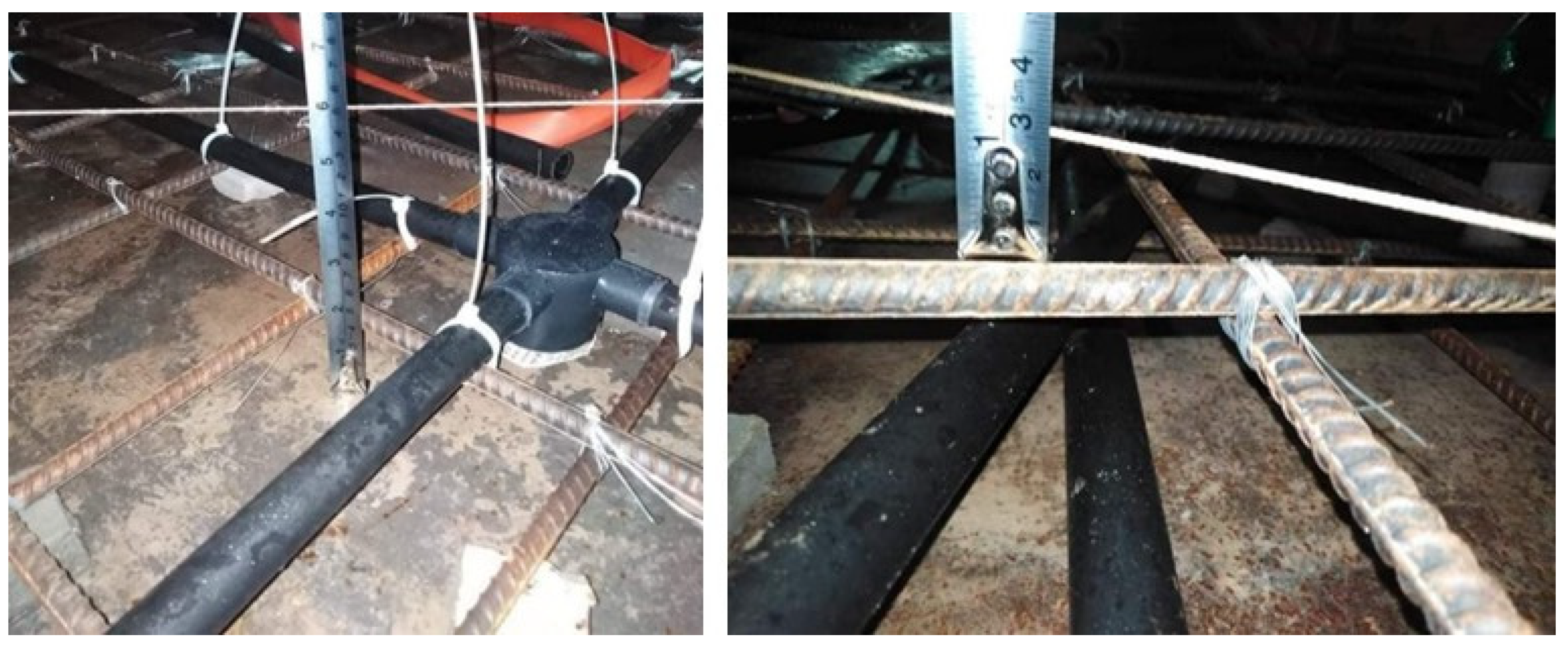
The corrosion of steel reinforcement is a leading cause of cracking in hardened concrete and its ultimate failure. Certain ways to avoid such damage include ensuring that the steel rebars are sourced from quality suppliers and that enough covers are provided as required in relation to the type and exposure condition of concrete elements. Furthermore, all covers for the rebars should be checked before pouring the concrete. An example of cover checking for rebars in the case of an elevated concrete slab is shown in
Figure 5. According to ACI Committee 318 [
27], depending on the bar size, the specified cover of a cast-in-place reinforced (non-prestressed) concrete slab is 1.5 to 2 in (38 to 51 mm) when exposed to weather, and 0.75 to 1.5 in (19 to 38 mm) when not exposed to weather.
Hardening concrete and formwork may also fail if they are accidentally impacted by a heavy falling object or other dynamic things during construction. Severe impact could cause concrete spalling and partial failure of the newly fabricated structural elements. Conventional concrete is designed to withstand various static loadings; however, it is not typically designed to bear high impact. In the case of dynamic loading, the better option will be to use fiber-reinforced concrete, as it possesses very high impact resistance [
28] and can resist crack propagation [
29].
4.3. Major Factors Surrounding the Design of Concrete Reinforcement
The design of concrete reinforcement largely depends on the space requirement of the end users and how they plan to use the building. If the span between the columns is very large, such as that for luxurious residential high-rise buildings, then the rebars must be designed accordingly to support the load between the columns. The large span could be chosen for open-concept residential units where it is intended to maximize the use of floor area within the units. Other examples for large spans can be for industrial applications such as in manufacturing plants, where the flow of materials and the movement of workers and machinery require a floor layout with less columns to minimize obstructions. An increased span increases the load on the structural elements, suggesting the need for a higher amount of rebars.
The authors determined from the interviews that the main factors surrounding the design of concrete reinforcement are the functionality of the structure and the load that will be applied to it, including the superimposed dead load, when deciding the strength of rebars and their spacing. For example, additional rebars are required to support the weight of books on the floors of a library building and heavy equipment such as an air handling unit on the roof of an industrial building. In addition, seismic loading is considered in the design of concrete reinforcement, depending on the geographic location of the buildings. In some locations, the loading arisen from frost heaving should also be considered in the case of foundation design. Considerations of such loading conditions will require extra rebars for the concrete buildings.
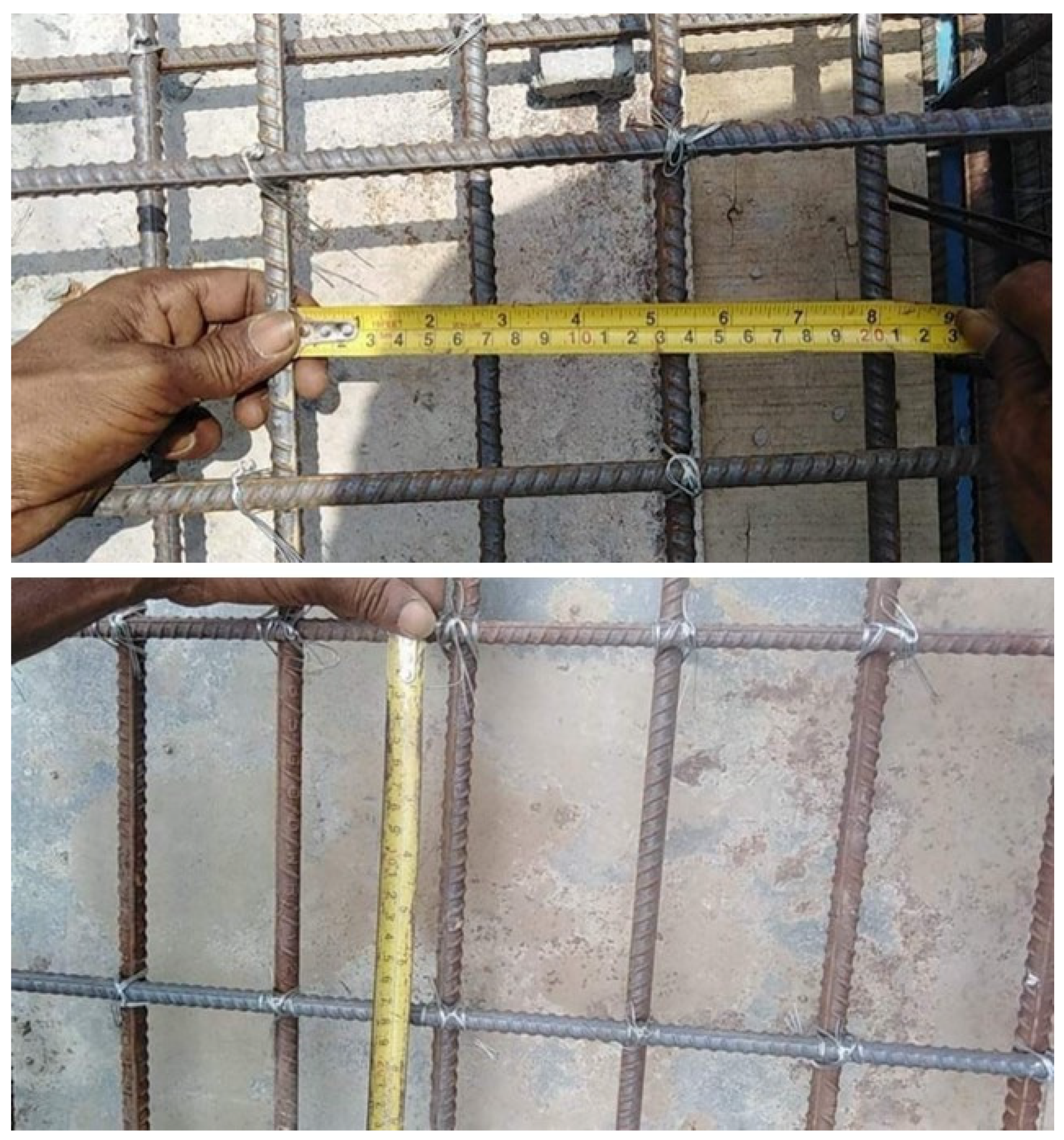
The design of rebars includes not only the reinforcement area and rebar size, but also the spacing between rebars. The rebar spacing should not be too large—this is because the rebars are often used as a working platform by the construction personnel, while casting horizontal structural elements (e.g., beam, slab). If the design calls for thicker rebars (>#8 (25M)) with larger spaces, it poses as a fall hazard for construction workers, as revealed from the interview results. Therefore, the rebar spacings (see
Figure 6) must be smaller than the smallest boot size so that workers can use the rebar surfaces safely.
The shear and lateral pressure applied on fabricated elements, construction loads being applied to the element before the proposed design load, and any embedded items (e.g., utility rough ins, as can be seen in
Figure 5) clashing with the reinforcement should also be considered during the engineering design phase of the concrete reinforcement. The shear and lateral pressures caused by some of the loads during construction can vary depending on the size of the element being poured and how it has been divided into pour breaks.
The size (diameter) and surface texture of rebars are the other factors in the design of concrete reinforcement. They have significant impacts on the performance of hardened concrete. This is because they affect the interfacial bond between concrete and rebars. Alharbi et al. [
15] reported, “Decreasing diameter of steel rebar from 16 to 12 mm yielded remarkable increase of bond strength by 20%.” In addition, bleed water and air migrate towards the surface of the concrete element as the heavier particles, such as coarse aggregates, settle due to gravity. They can be trapped under the horizontally embedded rebars. Furthermore, surface laitance and entrapped bleed water and air increase cavitation, leading to poor mechanical interlock between the top rebars and concrete [
17]. These negative effects will be reduced if rebars of smaller diameter are used in concrete.
4.4. Typical Compressive Strength of Concrete and Applications
The compressive strength requirement of concrete depends on the type of structures and the magnitude of applied loads. The construction of low-rise and mid-rise residential, industrial, commercial, and institutional buildings generally require a concrete compressive strength in the range of 25 to 35 MPa for footings, foundation walls, and slabs. To cut down the cost of construction, 20 MPa concrete can be used in some cases of residential footings when it is approved by the structural engineer. On the other hand, the contractors can ask the engineer to increase the strength if they think it may be inadequate for the load which will be applied to the concrete elements. However, it is important for the builders to never overshoot the strength that the specifications call for, as this would price them out of the job and out of the market.
The compressive strength of concrete with entrained air intended for exterior applications is generally higher (typically 32 MPa in Canada) to withstand the adverse effects of environments (e.g., wetting and drying, freezing and thawing). It can be significantly below 20 MPa (~6 MPa) if used in the caisson shoring wall around the perimeter of the building footprint, as a greater amount of the load is supported by steel soldier piles. In contrast, the footing and base of the tower crane are typically constructed with a 35 MPa concrete to support heavy applied loads.
High-rise structures require concretes possessing a compressive strength significantly higher than 40 MPa, particularly in the columns, piers, and foundation elements. In high-rise buildings, the compressive strength of the concretes used in footings, below-grade columns, and core walls generally lies in the range of 45–80 MPa. The core walls require a concrete compressive strength in the range of 60–80 MPa. However, a lower compressive strength is adequate for the core walls used in upper levels of the buildings. Moreover, the concrete strength of the slabs from the slab-on-grade to the various suspended slabs and composite decks falls within the range of 25–35 MPa. The above data imply that the strength of concrete is related to structural loads. The strength grade of concrete should be greater for higher applied loads [
27].
4.5. Criteria for Deciding Compressive Strength of Concrete
The most important factor when determining the compressive strength of concrete for use in construction is primarily the load which will be applied to the structures, as confirmed by all interviewees. The interviewees, however, mentioned that cost is also relevant in certain scenarios as a secondary factor. Although not a critical factor in design, the cost is important for the contractors to make profits from construction. Therefore, it is crucial to avoid overshooting the strength of concrete that the design calls for. This is because overdesigning a concrete mixture will drive up the price and minimize the profit margin in a construction job. In general, the most expensive constituent of concrete is cement. The cement content should be as low as possible for cost savings [
30]. Overdesigning a concrete mixture will require more cement and thus the overall cost will be higher.
In general, the compressive strength of concrete is always the lowest value approved by the structural engineer because the higher the strength of concrete, the more expensive it is. However, an early strength higher than what is called for could be achieved using a greater cement content if an element needs to have most of the design strength in an accelerated timeline for the purpose of rapid construction. Alternatively, an accelerator can be added to the concrete mixture to speed up the curing process. In each case, the cost of construction will increase due to over-spending on constituent materials (e.g., cement and accelerator). According to Dufferin Concrete [
31], the cost of accelerated strength gain mixtures will be 42–53 CAD higher if 75% of the design strength is intended to be achieved in 24 h. However, the higher cost can be balanced by the increased productivity of construction.
4.6. Occurrence of Concrete Demolishing and Repour due to Inadequate Strength
Concrete and rebars undergo rigorous testing before they arrive at a jobsite—concrete goes through a series of compressive strength tests and rebars are pre-tested in a lab for yield strength, ultimate strength, and stiffness. Hence, generally, it is not expected to have a reinforced concrete element of poor quality after casting that may require demolishing and repour if construction drawings and specifications are followed properly. To further ensure the quality at expected level, there is an insurance policy, which requires the concrete supplier to cover the cost of replacement if the fabricated concrete elements are not up to the required strength. This provision helps to ensure the desired quality of concrete, as no supplier would go for the loss of materials, labor, and energy due to resupply for repouring.
On jobsites, mistakes can happen that can lead to poor quality concrete requiring demolition and repouring. For example, the concrete elements may need to be demolished and repoured due to improper curing leading to inadequate compressive strength. When pouring concrete at a temperature of −20 °C, the curing of the concrete by heating should be continued by maintaining a minimum temperature of 10 °C [
32,
33]. The concrete will not cure properly if the temperature drops below 5 °C [
33]. In cold-weather concreting, the temperature can become significantly low due to heat loss overnight, when the temporary space heaters are malfunctioning, or when gas supply to the heaters is inadequate. In such cases, the concrete will not cure and will need to be chipped, rebar cleaned, and repoured. As a result, construction productivity will be affected with a schedule loss of several days (~3 to 4 days). In this kind of situation, a visual inspection shall prove the inadequacy of the concrete quality. When the concrete is severely weak, it will scrape off like chalk if a hammer is dragged through the finished structural element. This is an important lesson for builders, that environmental factors play a very influential role when dealing with the hardening of concrete, and a project team must have best work practices set in place to control these factors or use them advantageously if possible.
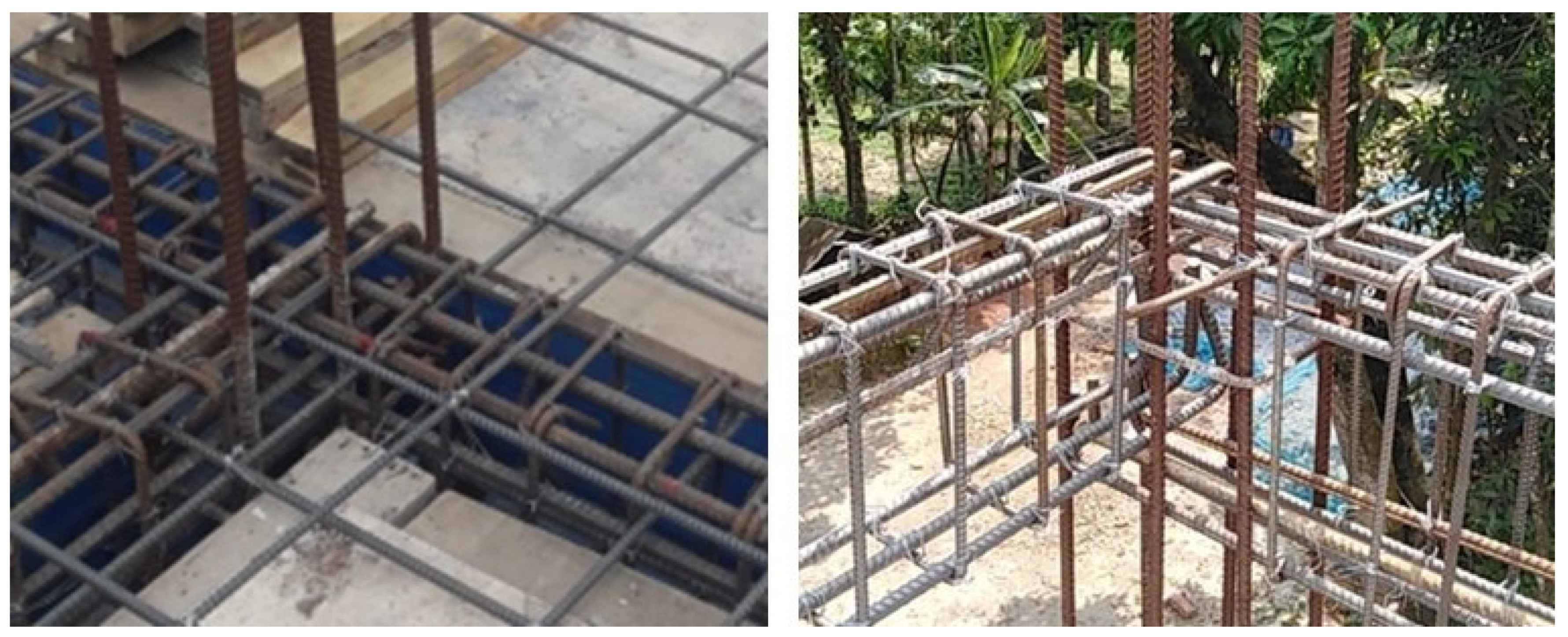
Sometimes the concrete may not attain the expected compressive strength due to inadequate compaction. This can occur when the rebars are congested and the concrete has a relatively low workability. Such a situation may arise in the case of high-rise construction or when the span between columns is increased for barrier-free space. In general, rebars become congested in beam–column intersections, as shown in
Figure 7, even in low-rise buildings. To get good compaction of the concrete in this kind of situation, a water-reducing admixture should be added to the concrete mixture for higher workability so that it can go around the rebars. However, it should be mentioned that an excessive amount of a water-reducing admixture can make the concrete too fluid, leading to a segregation problem, which could also affect the compressive strength of concrete.
The gain in compressive strength must be examined by testing the field concrete to decide if the concrete needs to be demolished and repoured. Testing will alert the project team that the concrete is not on track to reach the design strength and thus enable the team to take corrective actions in advance to minimize the schedule impact. The standard procedure of determining whether the concrete that composes a structure has adequate strength is by taking at least three test cylinders for the pour and test them for compressive strength at prescribed intervals—one cylinder is tested after 7 days, another after 28 days, and the remaining one is stored as a spare for use when one of the two compression tests is non-conclusive. The first test after 7 days will determine if the concrete is on track to reach the specified compressive strength by the 28-day period, and the second test after 28 days will be the deciding factor of whether the pour has successfully reached the design strength or not. Alternatively, a system of plugs can be placed throughout the concrete element. These plugs are removed as necessary during the curing period, and the resistance of the removal process can be used as a measure of what stage of the strength gain the concrete has reached and if the formwork is ready for stripping. Moreover, real-time embedded sensors can be used to determine whether the concrete is reaching the required compressive strength for formwork removal and if the contractor may proceed for further pouring. This will help to ensure that the fabricated concrete elements are not damaged during the construction stage due to early removal of formwork. In this regard, it should be mentioned that concrete strength may vary in a real structural element. Kanellopoulos et al. [
17] reported that the specimens from the top of the columns exhibited lower values of compressive strength, which gradually increased towards the bottom of the columns. They stated that the bottom half of vertically cast slender specimens is always better compacted than the top half regardless of the type of concrete mixture. This is important to note and to apply when out in the field to ensure that the concrete pour is well-compacted uniformly along the depth to ensure the required compressive strength throughout the element.
Demolishing and repouring may be required if some serious mistakes occur that adversely affect the quality of concrete. For example, addition of plasticizer by both the supplier and the field team due to lack of communication will harm the quality of the concrete. Adding excessive extra water for enhanced workability can also impair the quality of concrete. In such cases, the concrete may not reach the expected strength and other important properties, interfering with its performance. The excessive use of plasticizer can cause segregation of concrete during and after pouring. On the other hand, the use of extra water will increase the actual water-to-cement ratio. Consequently, the strength and other key properties (e.g., porosity, absorption, permeability) of the concrete will be affected. Therefore, extra water should never be added to the concrete. To ensure this, it is very important to create and monitor a paper trail of the water and additives that are added to the concrete mixture and the strength of concrete, so that the whole transition from the concrete supplier to the jobsite can be streamlined.
4.7. Curing Period and Process of Concrete
A curing period of 28 days is required for concrete to reach its full strength if no accelerator is used to speed up the curing process. However, the formwork can be removed within a few days—even the next day—after a pour and the construction work can proceed if the concrete has gained adequate strength to sustain construction loads. It is an industry standard to proceed with construction sooner than 28 days to keep the workflow underway given that only partial load (e.g., construction load) instead of the full design load is applied to the concrete element, as can be found from “Guide to Formwork for Concrete” [
34]. Construction loads can be applied the next morning after a pour, particularly when an accelerator is used in the concrete mixture; however, it should always be approved by a structural engineer.
In the construction industry, after pouring, concrete which includes an accelerator is generally left for 3–4 days to cure before construction loads are applied to it. The use of an accelerator is conducive to achieving high early strength [
35]. Hence, the early removal of formwork will be possible for such a concrete. In addition, some accelerators used to speed up the curing process allow concrete to be poured in −2 °C due to their chemical compositions that do not let the concrete freeze and make it easy to finish.
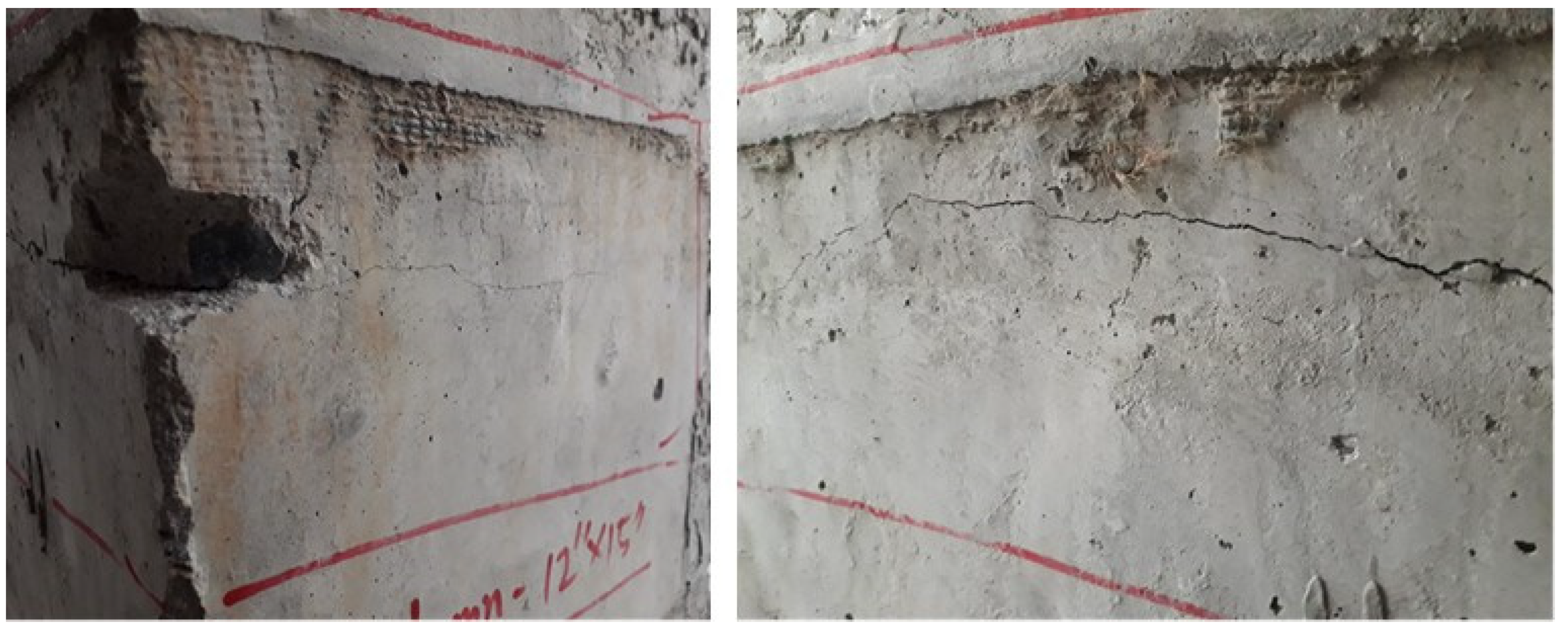
The minimum curing period should be 7 days in certain cases, such as for the concrete used in a crane base, before the crane can proceed with the early stages of erection. However, the crane base must reach to the full 28-day curing period for the concrete to achieve the maximum compressive strength before the crane can become operational. Nevertheless, it is important to note that in all cases the full design load of the structure should never be imposed on the concrete until it reaches the maximum strength. Otherwise, the newly cast structural element will crack, as shown in
Figure 8, where cracking occurred because the column did not gain enough strength to carry the construction loads and the dead load (self-weight) of the slab.
Curing is linked with the time for stripping the formwork. The strength gain of concrete through the curing process is used to decide when the formwork can be removed. Except for hanging walls, the formwork for vertical concrete elements can be removed at a minimum of 12 MPa, because at this strength concrete is self-standing. As for horizontal elements, they must be at 70% of the design strength before the formwork is removed [
36]. In any case, the strength gain depends on the curing method and period. To aid the curing process, certain chemicals (e.g., curing compounds) can be applied on the surface of the formed elements following the day of the pour to stop dehydration and reduce the surface cracking of concrete.
Faster curing will contribute to an increase in construction productivity, particularly in the case of high-rise buildings, as it allows the formwork to be removed sooner than 28 days. In this case, keeping three floors below with re-shoring (see
Figure 9), the next upper floor can be constructed. By the time the next floor is being poured it has not been 28 days, but it surpasses the industry standard for continuing construction, as the full design load is not being applied to the structure. Moreover, covering with a tarp and then heating the concrete slab from underneath can be implemented to accelerate the strength gain in concrete. The use of a tarp helps to trap the heat, which hastens concrete curing. In addition, the use of a tarp can prevent the interference of wind and rainfall, thus creating an overall controlled environment given that the building envelope is not yet installed. Tarping and heating allow the concrete to cure faster, and the three-step process of form, pour, and strip can cycle at an average of one floor per week. In this case, three crews can be divided between three floors, and the project can progress rapidly.
4.8. Hazards in Forming, Reinforcing, and Pouring of Concrete
There are a wide range of hazards that could be present on a construction jobsite. The most critical hazards are associated with working at heights and below grade. The other hazards are involved with improperly installed scaffolding, deep vertically cut excavations without adequate shoring, jagged rebar ends protruding without safety caps or troughs, concrete spillage, cement burn, dropped objects, and worker fatigue due to heavy lifting.
Working at building foundation level involves more risks. This is because that part of the construction work occurs below the grade and in a confined space. Working at heights also includes higher risks. Laborers could fall and thus injuries or even deaths may happen if proper safety measures are not taken. Moreover, heavy equipment such as cranes and concrete pumps are involved in concrete construction; safety precautions are required while operating them.
Leading-edge works are also associated with hazards. Certain hazards arising from concrete forming are related to inefficient housekeeping and material handling. Furthermore, hazards that can arise from concrete reinforcing include dropped objects, heavy loads, and worker fatigue due to material weight. Cement burn is another hazard that arises from concrete pouring. Many construction workers may not be aware of the consequences that stem from concrete contacting skin. It is cement, the binding component of concrete, which causes chemical burn [
38]. Workers exposed to concrete are at risk of cement irritation, which can result in third degree burn on the skin.
Hazards occur during concrete works and can be avoided by ensuring that a concrete pour is not scheduled for afternoon on a Friday to make sure that the workers are mentally engaged. Furthermore, the pour rate must be staggered properly, and the associated housekeeping must be maintained when dealing with concrete spillage. If concrete spillage is not cleaned properly off the side of a gang-form, when the crane hoists this form 200 ft (61 m) in the air, the uncleaned concrete can fall off the side and cause severe injuries to the workers below. Therefore, materials handling and cleaning are very important.
4.9. Safety Requirements in Concrete Works
The safety on construction jobsites can be enhanced by ensuring that the general contractors prepare their engineered formwork system according to the shop drawings approved by the engineer. A field engineer must be involved when moving climbing and flying forms in high-rise construction. Furthermore, checklists and inspections may help to minimize many job hazards in construction sites. For example, leading-edge job hazards can be mitigated using appropriate prework checklists and inspections. Some hazards arising from concrete reinforcing can also be mitigated by proper prework checklists and inspections. Moreover, certain hazards evolving from inefficient housekeeping and materials handling can be mitigated by designating laydown and work areas as well as central activity zones for worker overlap, employing adequate manpower to reduce travel distance, and giving enough breaks to rest and stretch.
For construction workers, working at height is associated with high job hazards. In terms of safety, all workers working at heights must have certified working-at-heights training and workers’ compensation. In addition, they need to fulfill the requirements set by the government (e.g., Ministry of Labor). They must understand that safety is non-negotiable. Fall arrest systems are typically required for working at heights. All laborers who are working at heights must be clipped to prevent themselves from falling (see
Figure 10). They need to use proper tie-offs when working at a height of 6 feet or more. Alternatively, wherever applicable, engineered guardrails (refer to
Figure 9) can be used for fall protection to avoid injuries leading to the death of construction personnel.
Appropriate safety measures must be taken to avoid cement burn. Construction professionals must wear rubber boots while pouring and compacting concrete to protect their feet from cement burn (see
Figure 11). Other control measures such as wearing latex gloves, rain pants, safety glasses, washing of the skin, and use of certain moisturizers should be adopted for concrete jobs.
In terms of safety, the other major things that need to be considered are adequate access and egress and compliance with the engineering drawings. The protruded rebar ends should also be covered with safety caps (see
Figure 12). Moreover, the safety requirements should not be just based around the workers and the surrounding environment, it is also very important to ensure that the equipment are in safe working order [
40]. Lifting heavy loads (e.g., formwork, falsework, concrete bucket) safely requires that the crane has adequate lifting capacity, and the rigging points are flawless. Therefore, the crane and rigging points must be inspected to ensure compliance with safety standards before lifting heavy loads.
Job hazard analysis as well as pre-job safety inspections should be carried out in a construction project—all tasks should be carefully reviewed so that all the hazards and controls of those tasks can be identified. There should be enough details included in each section of construction work so that a worker can comprehend the tasks. High-risk activities must be identified and explained to the workers before they start the job. Furthermore, the necessary fall restraint, travel restraint, or fall arrest system must be in place and in good working order. Any sub-trades that will perform certain work onsite must assess the working conditions and fill out the required safety document before commencing the duties.
4.10. Most Severe Safety Infractions That can Occur during Concrete Works
Most severe safety infractions can occur when a customer refuses to pay for lagging and pile shoring, creating a huge risk for construction workers if they are allowed to do the job. It is unsafe and illegal to send workers into an excavation that does not have a shoring system in place. Other serious safety infractions can happen when lifting the gang form or flying the large table form if a tower crane is not operated carefully and pinching of the rigging occurs. In severe situations of such a case, the boom of the crane can dip towards the ground and the cable can snap, shooting up in the air and wrapping around the boom. Moreover, the boom of the concrete pump may collapse onto the building due to a hydraulic failure while concrete pouring, thus creating a high risk to the safety of the construction workers. Such a safety infraction could be avoided by thorough inspection and timely maintenance of the equipment. Therefore, the necessary visual inspections of the equipment should be performed before using them in construction works.
Unsafe circumstances and disobeying work procedures can lead to fatalities in construction. Severe safety infractions can occur if construction workers are allowed to work at night after regular working hours in the absence of a rescue person or team. In such a situation, unexpected accidents can happen, and injured workers may not get any immediate help. Furthermore, sometimes serious accidents can occur if construction workers ignore safety protocols and do not follow the instructions of the engineer. For example, the engineer usually suggests casting the balconies and cantilever beams starting from the inner side and then working towards the outer side of the formwork. Instead, if the construction workers start casting from the outer side of the formwork system, it will cause loading on an area which is not adequate to withstand the weight of the concrete without the lateral support from the inside face, and therefore, collapse may occur. Hence, construction workers must follow the instructions of the engineer.
The top safety infraction on any job for most structures can happen while working at heights. In a concrete construction jobsite, the working area is constantly evolving with the pouring of structural elements; hence, it can prove to be a challenge to maintain leading-edge protection for the workers. The sturdier guardrail system must be used for working at heights. It will prevent the workers from falling, thus avoiding any fatal accidents. Further action that can be taken to stay on top of safety is to hold scheduled meetings with the team to develop an adaptable safety plan as the project progresses. This should be part of the action items for safety in construction [
42]. Such approach will ensure that appropriate plans are ready and in place for the leading-age and working-at-height construction jobs.


