Abstract
The aim of this study is to improve the shear behavior of reinforced concrete (RC) beams with stirrups by using highly ductile fiber-reinforced concrete (HDC), which is a fiber-reinforced cement-based composite material with tensile-strain-hardening properties. Twelve reinforced HDC (RHDC) beams and three RC beams with stirrups were tested under a concentrated load. The experimental parameters involved the shear span to effective depth ratio, stirrup ratio, and longitudinal reinforcement ratio. The results revealed that the mode of failure of RHDC beams, which exhibited better ductility than RC beams, included diagonal compression, shear compression, diagonal tension, and flexural shear failure. RHDC beams exhibited stable multiple crack propagation behavior and satisfactory integrity, thus showing that HDC effectively restricted the development of shear cracks and improved the damage resistance of beams. Compared with RC beams, the shear strength, displacement ductility factor, and deflection-clear span ratios corresponding to the peak load and ultimate deflection increased by up to 30.5%, 44.9%, 150.0%, and 148.0%, respectively. RHDC beams exhibited higher residual strength and deformation capacity than RC beams, thus indicating that HDC significantly improved the brittle shear failure mode. Specimens H-1 and H-2 exhibited the largest improvement in shear strength and displacement ductility factor, respectively, compared with RC beams. The shear strength of RHDC beams increased as the shear span to effective depth ratio decreased. For RHDC beams with the same shear span to effective depth ratio, the shear strength increased with the increase in the longitudinal reinforcement ratio and stirrup ratio under shear compression failure.
1. Introduction
Shear failure in reinforced concrete (RC) beams is brittle, and brittleness increases significantly with increase in concrete strength. The brittle behavior often aggravates the failure of key parts of structural components under continuous earthquake action, thereby complicating post-earthquake repair. Moreover, RC beams, which may have large deformations and be easy to crack, are the energy dissipation components of structural design. These components are controlled by their serviceability limit state. The application of high-strength concrete is restricted in beams because of brittleness. Therefore, it is important to improve the deformation capacity and brittle shear failure mode of high-strength concrete beams, for enhancing load-carrying capacity and ductility, and controlling the seismic damage experienced by structures.
Notable studies are underway to create new ductile composites to increase the shear strength and plastic deformation capacity of concrete structural components. Highly ductile fiber-reinforced concrete (HDC) [1] is a type of fiber-reinforced cement-based composite material similar to engineered cementitious composites (ECC) [2,3,4], high-performance fiber-reinforced cementitious composites (HPFRCC) [5,6,7] and strain-hardening cementitious composites (SHCC) [8,9], which exhibit excellent tension strain-hardening behavior and multiple cracking mechanisms. Furthermore, HDC has high deformation capacity and compressive toughness under uniaxial compression, and the peak compressive strain of HDC is approximately 2–3 times that of normal concrete [10].
Owing to their excellent mechanical properties, fiber-reinforced cement-based composite materials have been widely applied in structural elements. Yoo [11] and Kachouh [12] conducted an experimental study on the shear behavior of steel-fiber-reinforced concrete beams without stirrups, which showed that the application of steel fibers improved the rigidity and ductility of beams. Yuan [13] that ECC short beams had better shear resistance under cyclic loading. Reinforced fiber-reinforced concrete (RFRC) beams exhibited higher shear resistance and shear crack distribution with and without stirrups [14,15,16,17]. Alrefaei [18] performed an experimental investigation on the shear behavior of hybrid fiber-reinforced cementitious composite (HFRCC) beams, which showed that their shear strength, multiple cracking behaviors, and shear strain capacity improved considerably. Paegle [19] and Hossain [20] investigated the shear behavior of novel hybrid composite beams made of self-consolidating concrete and ECC. The results indicated that the beams exhibited higher ductility and energy absorption capacity. Hou [21] investigated the shear behavior of reinforced ultra-high toughness cementitious composite beams, with a shear span to effective depth ratio of approximately three. The results showed that the number and total openings of diagonal cracks decreased with the increase in stirrup ratio. The results by obtained by Deng [22,23,24] showed that HDC distinctly improved the failure mode and shear strength of steel-reinforced HDC deep beams. ECC short columns [25] and ECC jacketed short columns [26] exhibited significant improvement in plastic deformation ability under lateral cyclic loading, compared to the control specimens. The application of fiber-reinforced cement-based composite materials in joints [27,28,29] and plastic hinges [30] enhanced shear capacity and damage-tolerance capacity. The aforementioned studies have indicated that fiber-reinforced cement-based composite materials improved the brittle failure mode, crack control capacity, plastic deformation capacity, damage resistance, and shear strength of specimens dominated by shear. However, understanding of the shear behavior of polyvinyl alcohol (PVA) fiber-reinforced concrete beams with stirrups is very limited. Mohamed et al. [31] investigated the effect of shear span to depth ratio and stirrups ratio on the shear behavior of PVA-ECC beams with stirrups. Dan et al. [32] studied the flexural and shear behavior of PVA-ECC beams with different longitudinal reinforcement and stirrup ratios. Research on the shear behavior of reinforced HDC beams considering various influence factors remains insufficient for providing a full experimental basis for establishing building-design criteria.
In this study, the application of HDC aimed to improve the brittle shear failure mode, shear strength, deformation capacity, and damage resistance of high-strength concrete beams with stirrups, to reduce the cost of post-earthquake repair. Twelve reinforced HDC (RHDC) beams and three RC beams with stirrups were prepared and tested under a concentrated load. The experimental parameters involved the shear span to effective depth ratio, longitudinal reinforcement ratio, and stirrup ratio. The shear performance of the beams was evaluated based on crack patterns, failure mode, load-deflection behavior, deformation capacity, and shear strength.
2. Experimental Programs
2.1. Material Properties
2.1.1. HDC
The main components of HDC used in this study were ordinary Portland cement (42.5R), I-level fly ash, local river sand (maximum aggregate size: 1.18 mm), water, and PVA fibers. The volume content of PVA fibers was 2%. The properties of the PVA fibers are listed in Table 1. The mixture proportions of HDC are shown in Table 2. The chemical composition for cement and fly ash are listed in Table 3. The average compressive strength of HDC was 66.16 MPa, obtained by performing the compressive test using six cubes with a side length of 150 mm. The average tensile strength of HDC was 6.34 MPa, determined by performing a uniaxial tension test on dog-bone specimens of 350 mm × 50 mm × 15 mm. The test setup, tensile stress–strain curves, and crack patterns of HDC are shown in Figure 1.

Table 1.
Properties of PVA fibers.
Table 2.
Mixture proportions of HDC (kg/m3).
Table 3.
Chemical compositions of cement and fly ash.

Figure 1.
Uniaxial tensile tests: (a) test setup; (b) stress–strain curves and crack pattern.
2.1.2. Concrete and Steel Reinforcement
The concrete used in this study was designed to have a strength grade of C60 [33] Compression tests were performed on the concrete, using six cubes in sections of 150 mm × 150 mm × 150 mm. The average compressive strength of the concrete was 72.59 MPa. The tensile strength of the concrete was 4.17 MPa, according to [34]. The mechanical properties of the steel reinforcement used in this study are listed in Table 4. , , and are the yield strength, ultimate strength, and yield strain of the steel reinforcement, respectively.
Table 4.
Mechanical properties of steel reinforcement.
2.2. Beam Specimens
Twelve RHDC beam specimens and three RC beam specimens with stirrups were cast and tested. All the beam specimens were reinforced with HRB400 steel bars and HPB300 stirrups. Two 8 mm diameter steel reinforcement bars (HPB300) were used as top bars to fix the stirrups. The longitudinal reinforcement ratios of all the beams were relatively high, to ensure the occurrence of shear failure. The thickness of the concrete cover was 10 mm. Specimens C-2 and H-2 are given as an example for the dimensions and steel reinforcement details of the beam specimen, as shown in Figure 2. Details of all beam specimens are given in Table 5. For the notation of beam specimens, the letters C and H denote the RC and RHDC beams, respectively, and the numbers denote the shear span to effective depth ratio (). The letters a, b, and c denote the different stirrup ratio and longitudinal reinforcement ratios, respectively. For instance, H-1a indicates a RHDC beam with , and the corresponding variate is the stirrup ratio.
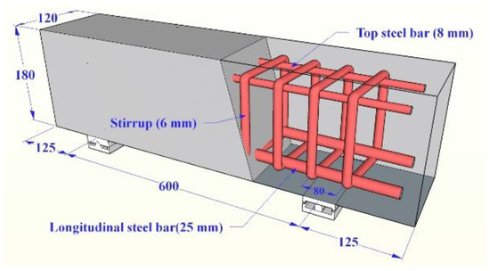
Figure 2.
Dimensions and steel reinforcement details of specimens C-2 and H-2 (units: mm).
Table 5.
Specimen parameters.
2.3. Test Apparatus
The beam specimens were subjected to a concentrated load using a 5000 kN electrohydraulic servo testing machine, after curing at room temperature for 28 days. The steel plate was placed at the loading point and sand was used for leveling to prevent the local crushing of the beam specimens. The load was applied under displacement control at a rate of 0.2 mm/min [35]. Three linear variable differential transducers (LVDT) were installed at the supports and at the mid-span of the specimens, for displacement monitoring. Additionally, three strain gauges were included in the tensile steel reinforcement to record the strain development at the mid-span and near the supports. The stirrups were symmetrically instrumented with the strain gauges along the shear span to measure whether the stirrups would yield. The LVDT and strain gauges were connected to the TDS-602 data acquisition system. The test apparatus was similar for all the beam specimens. For simplicity, consider the test apparatus of specimen C-2 as an example (Figure 3). The beam ends extend outward by 125 mm, 270 mm, and 150 mm at the supports when , , and , respectively.
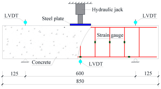
Figure 3.
Test apparatus for specimens C-2 (units: mm).
3. Test Results and Discussion
3.1. Crack Patterns and Failure Modes
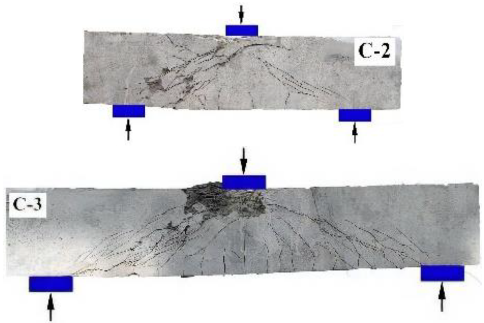
Table 6 and Table 7 show the crack patterns and failure modes of RC beam specimens and RHDC beam specimens, respectively. RC beam specimens failed in diagonal compression and shear compression modes, whereas RHDC beams failed in diagonal compression, shear compression, diagonal tension, and flexural shear modes.
Table 6.
Crack patterns and failure modes of RC beams.
Table 7.
Crack patterns and failure modes of RHDC beams.
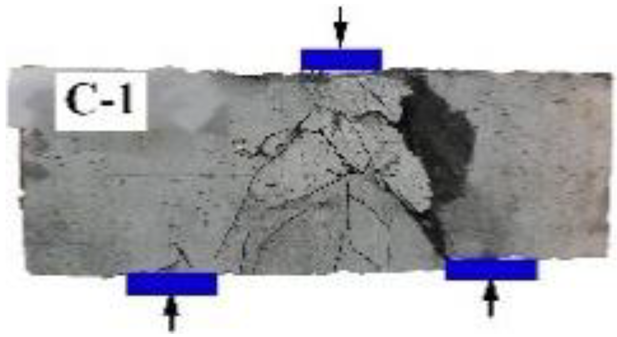
3.1.1. RC Beam Specimens
- (1)
- Diagonal compression failure
Specimen C-1 failed in brittle diagonal compression mode. The first diagonal shear crack appeared in the web of the beam within the shear span at a load of 149 kN. The web on the right side of the beam was divided into several diagonal compression struts by diagonal cracks at a load of 373 kN. As the load increased, the diagonal compression struts were crushed. Then, the load decreased at a fast rate. Finally, the beam failed in brittle shear mode with the crushing and peeling-off of the concrete.
- (2)
- Shear compression failure
Shear compression failure was observed in specimens C-2 and C-3. The first diagonal shear crack occurred in specimen C-2 at a load of 89 kN. The stirrups started to yield when the load reached 148 kN. A major diagonal shear crack formed at a load of 257 kN. Ultimately, the beam failed because of the crushing and peeling-off of concrete in the shear-compression zone. Additional cracks and severe peeling-off of concrete was observed in specimen C-3, owing to the increase in the shear span to effective depth ratio.
3.1.2. RHDC Beam Specimens
- (1)
- Diagonal compression failure
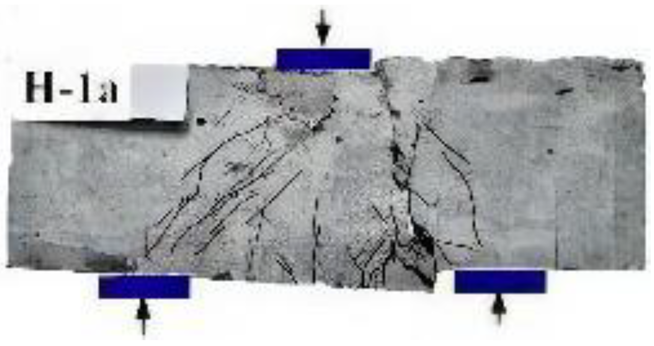
Specimens H-1, H-1a, H-1b, and H-1c failed in diagonal compression mode, with similar crack distributions. When the load reached 119 kN, the first diagonal shear crack occurred in specimen H-1. As the load reached 497 kN, a major diagonal shear crack formed, and several fine diagonal cracks were observed nearby. The load-carrying capacity began to decrease. Subsequently, shear dislocation increased on both sides of the major diagonal shear crack. The interlock force of the aggregate was weak, owing to the absence of coarse aggregates in HDC, accounting for the larger shear dislocations of the RHDC beams. Finally, the beams failed in shear with a certain ductility and high residual strength.
- (2)
- Shear compression failure
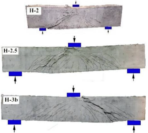
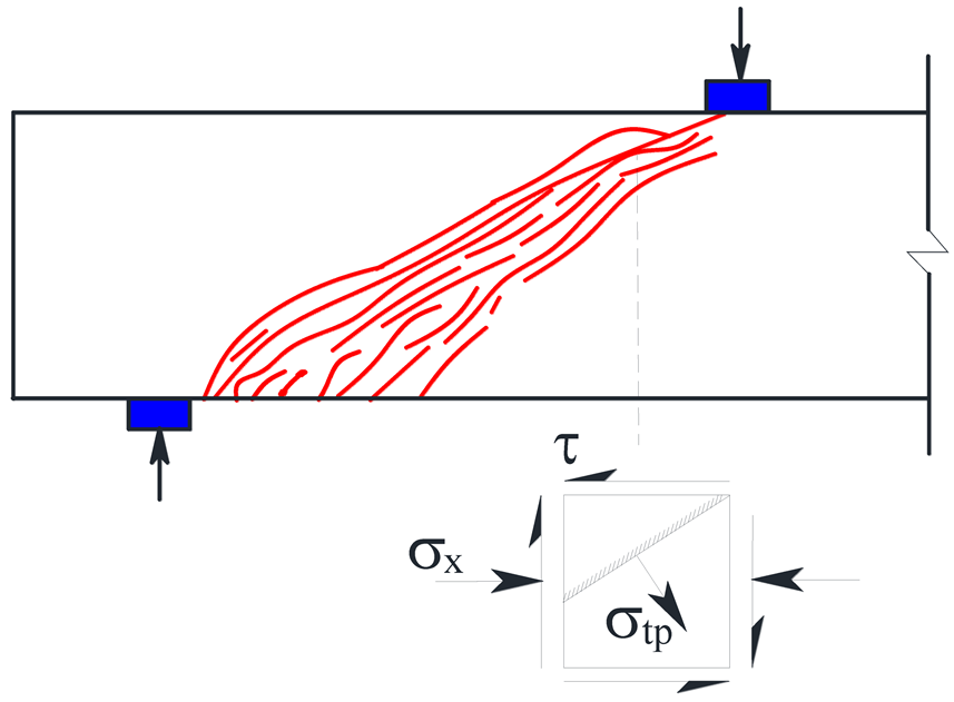
Specimens H-2, H-2a, H-2c, H-2.5, and H-3b failed in shear compression mode, with similar cracking patterns. Compared with specimen C-2, the cracking load (first diagonal shear crack) of specimen H-2 was improved by 47% (131 kN) owing to the excellent tensile property of HDC. With an increase in load, the stirrups intersecting with diagonal cracks began to yield. Multiple fine cracks appeared at the loading point. The load increased slowly after reaching the yield state. A major diagonal shear crack occurred in the shear-span region. With a further increase in load, the major diagonal shear crack widened at a slow rate. Additional diagonal cracks and large compressive deformation were observed in the shear-compression zone. Finally, the beam failed in shear with a certain ductility, good integrity (no HDC cover peeling-off), and high residual strength.
- (3)
- Diagonal tension failure
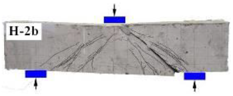
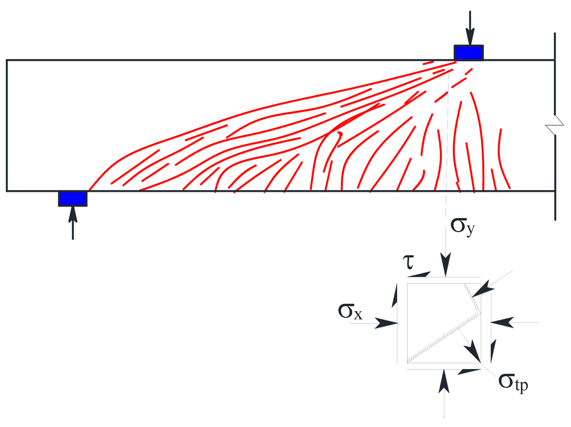
Specimen H-2b failed in diagonal tension mode. The first diagonal shear crack occurred at a load of 91 kN. With a further increase in load, the stirrup began to yield. As the load reached 354 kN, a major diagonal shear crack was observed, after which the load-carrying capacity of the specimen began to decrease. Subsequently, the major diagonal shear crack widened and extended to the loading point, thereby causing the beam to fail in shear with a high residual strength.
- (4)
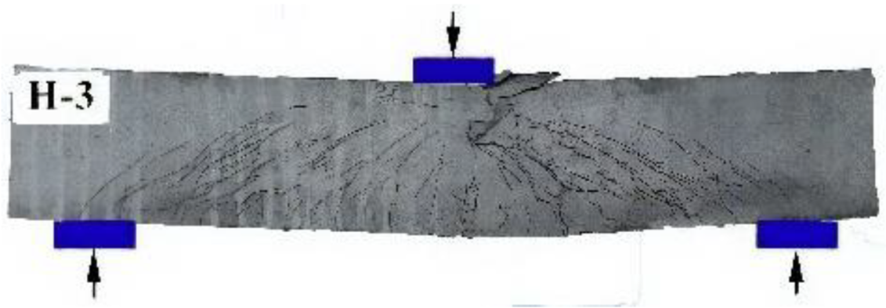
- Flexural shear failure
Specimens H-3 and H-3a failed in flexural shear mode, with similar cracking patterns. The first vertical crack of specimen H-3 was observed in the tension zone at a load of 108 kN. The first diagonal shear crack occurred in the web of the beam within the shear span at a load of 201 kN. The stirrup and longitudinal reinforcement began to yield when the load reached 483 kN and 590 kN, respectively. The yield state was achieved with the appearance of many fine vertical cracks at the bottom of the beam. Subsequently, a major diagonal shear crack formed and the vertical cracks widened at the mid-span section. Thereafter, the load-carrying capacity began to decrease. Finally, a large compressive deformation was observed in the HDC in the shear-compression zone. The top steel reinforcement buckled and the HDC crumbled on the left side of the loading point. The beam failed in flexural shear mode when the HDC attained the ultimate compressive strain in the shear-compression zone.
3.2. Discussion of Failure Modes
3.2.1. Diagonal Compression Failure
The RC beam specimen C-1 failed in diagonal compression mode when the shear span to effective depth ratio was relatively small (). The stirrups did not attain the desired yield strength. However, the beams showed high shear strength, small deformation, and brittle behavior.
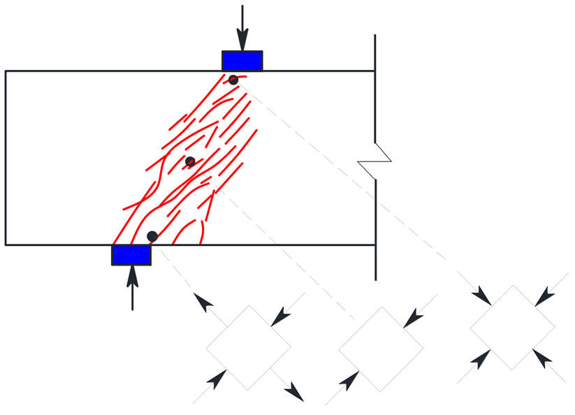
As the shear span to effective depth ratio was small (), diagonal compression failure was observed in RHDC beam specimens H-1, H-1a, H-1b, and H-1c. The diagonal compression failure of RHDC beams was observably different from the diagonal compression failure of RC beams. The stirrups did not achieve the yield strength. RHDC beams exhibited multiple diagonal cracks with small crack width. A major diagonal shear crack formed in the web of the beam when the transverse tensile deformation of the diagonal compression struts exceeded the ultimate tensile strain of HDC. After the appearance of the diagonal crack, the strain in the stirrups increased slowly because the shear load was resisted by the stirrups and the HDC. The beam exhibited favorable plastic deformation capacity before the HDC in the shear-compression zone where it reached the ultimate compressive strain. The diagonal compression struts between the loading point and the support maintained satisfactory integrity, which was attributed to the excellent compressive toughness of HDC. Distinct from the brittle failure of RC beams, RHDC beams with diagonal compression failure exhibited high residual strength, with large shear dislocations on both sides of the major diagonal shear cracks. The reason for the large shear dislocations in RHDC beams is that the interlock force of the aggregate was weak, owing to the absence of coarse aggregates in HDC. Compared with RC beams, RHDC beams showed higher shear strength and larger deformation capacity, because the strength and deformation capacity of HDC exceed those of concrete under diagonal compression.
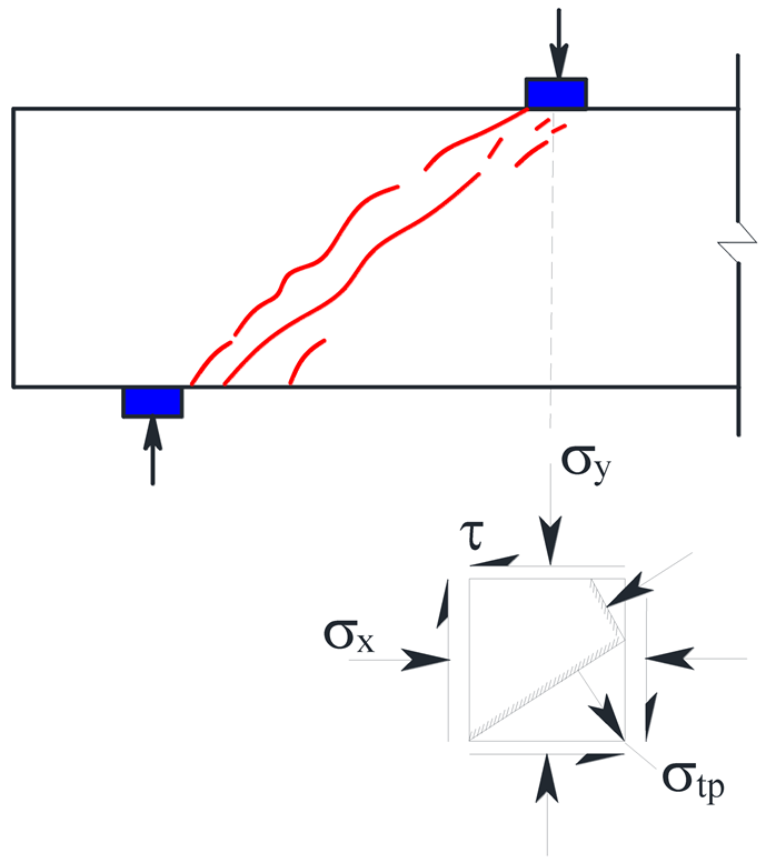
3.2.2. Shear-Compression Failure
RC specimens C-2 and C-3 failed in diagonal compression mode when the shear span to effective depth ratio was appropriate ( and ). The stirrup intersecting with diagonal cracks attained the yield strength. Moreover, the specimen with shear compression failure exhibited lower shear strength, slightly larger deformation, and brittle behavior.
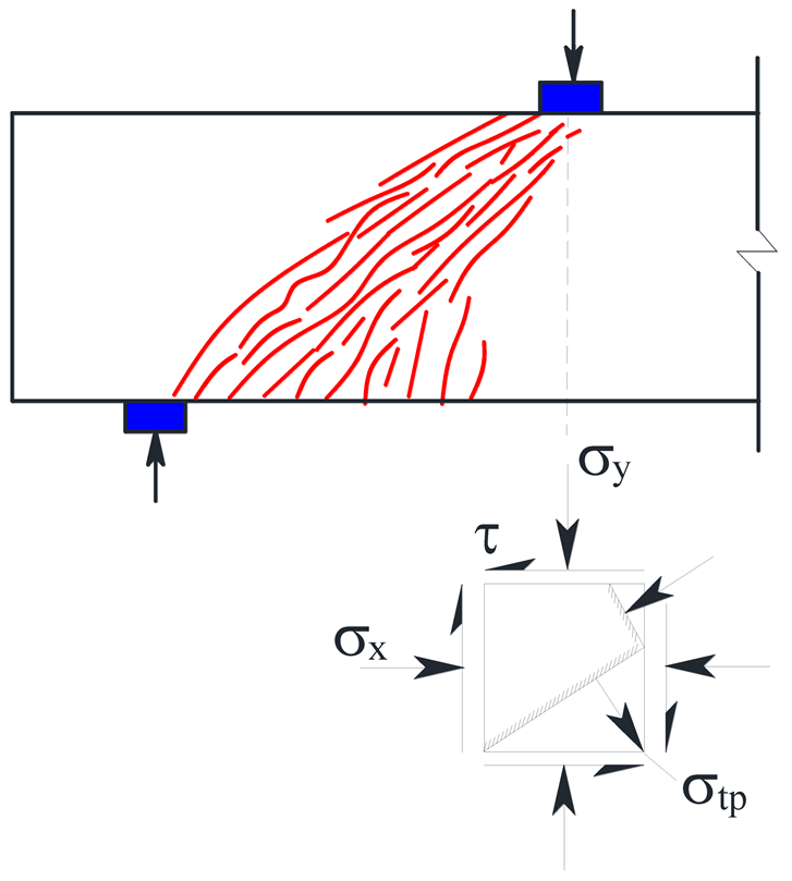
Shear ompression failure occurred in RHDC specimens with an appropriate shear span to effective depth ratio (, , and ), e.g., H-2, H-2a, H-2c, H-2.5, and H-3b. Shear cracks with small width occurred in these beams, which showed multiple cracking modes. The major diagonal shear crack formed in the web of the beam when the major tensile strain of HDC in the shear span exceeded the ultimate tensile strain. Subsequently, the load-carrying capacity of the beam continued to increase, mainly owing to the fiber bridging effect of HDC and the addition of stirrups, thereby exhibiting favorable plastic deformation capacity. RHDC beams formed a diagonal tensile stress field along the direction of the major tensile stress, due to the excellent tensile-strain-hardening properties of HDC. A large compressive deformation was observed in the shear-compression zone in the failure state. For stirrups intersecting the diagonal crack, the yield strength was attained at a slower rate owing to the shear contribution of HDC. Finally, the beam failed in shear when the HDC in the shear-compression zone reached ultimate compressive strain.
3.2.3. Diagonal Tension Failure
RHDC specimen H-2b failed in diagonal tension mode because of the large stirrup interval. Many vertical and diagonal cracks with small spacings were observed in the shear-span region of the beam. A major diagonal crack formed in the web of the beam when the HDC of the shear-tension zone reached ultimate tensile strain. Eventually, the stirrups yielded and the beam failed in shear with a high residual strength. However, HDC continued to provide tensile stress after cracking, and the diagonal tensile stress field formed in the shear span, owing to the tensile-strain-hardening characteristic and fiber-bridging effect of HDC. Therefore, deformation capacity after the occurrence of diagonal cracks was significantly improved along with shear strength.
3.2.4. Flexural Shear Failure
RHDC specimens H-3 and H-3a failed in flexural shear mode. The tension zone and shear-span region of the beam exhibited multiple cracking. During testing, the longitudinal reinforcement yielded, which was followed by the formation of the main flexural crack. The major diagonal crack occurred when the HDC of the shear-tension zone reached the ultimate tensile strain. The beam failed because the HDC of the shear-compression zone attained the ultimate compressive strain. Furthermore, the HDC of the shear-compression zone experienced a large compressive deformation. For RHDC beams with flexural shear failure, the yield point was dependent on the flexural capacity, while the occurrence of major diagonal cracks depends on the ultimate tensile strain of HDC. The final failure depends primarily on the composite strength of HDC in the shear-compression zone.
In summary, the shear strength and deformation capacity of RHDC beams were much greater than those of RC beams, owing to the higher ultimate tensile strain and ultimate compressive strain of HDC. Furthermore, the shear strength of RHDC beams improved significantly compared with RC beams even though the compressive strength of HDC was slightly lower than that of concrete in the test. The results indicate that the excellent tensile deformation capacity of HDC effectively restrained the development of diagonal shear cracks, prevented the collapse and peeling-off of the concrete cover, improved the damage resistance, and realized the ductile shear failure mode.
3.3. Load–Deflection Behavior
Figure 4 illustrates the load–deflection curves of all beam specimens. The load and the corresponding deflection at shear cracking (i.e., and ), yield (i.e., and ), major diagonal crack (i.e., and ), and peak (i.e., and ) points are presented in Table 8. The shear cracking and major diagonal crack points were determined by the occurrence of the first diagonal shear crack and the major diagonal crack, respectively. The yield point is obtained using the energy method introduced in [36]. The ultimate deflection () corresponded to the point where the load decreased to 85% of the peak load. The deflection to clear span ratio , displacement ductility factor [37], and the values proposed to eliminate the influence of the effective cross-sectional area are listed in Table 8; see also Figure 4.
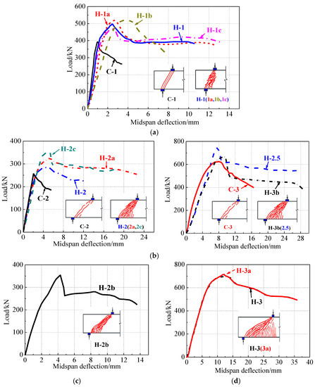
Figure 4.
Load–deflection curves. (a) Diagonal compression failure, (b) shear compression failure, (c) diagonal tension failure, (d) flexural shear failure.
Table 8.
Test results.
(1) Specimen C-1 failed in diagonal compression mode, whereas specimens C-2 and C-3 failed in the shear compression mode. RC beams exhibited brittle failure at the peak load. Among the various failure modes, diagonal compression failure was the most prominent, whereas shear compression failure rates were slightly better. Compared with RC beams, RHDC beams experiencing shear compression failure demonstrated a change in the slopes of the load–deflection curves and exhibited a slower rate of decrease in shear strength, thereby showing distinct gradual nonlinear characteristics. This is because the favorable tensile-strain-hardening characteristics and fiber-bridging effect of HDC maintained higher stiffness and shear strength in the specimens after the appearance of multiple diagonal cracks. RHDC beams exhibited lower stiffness compared to the reference RC beams, due to the lower elastic modulus of HDC compared with that of normal concrete [38,39].
(2) For RHDC beams with diagonal compression failure, the load–deflection curves were approximately straight before cracking. Changes in the slopes of the load–deflection curves represent the development of cracks and yielding of stirrups. A decrease in the load-bearing capacity was observed after the occurrence of large shear dislocations. The beam exhibited a certain ductile shear failure with high residual strength.
(3) For RHDC beams experiencing shear-compression failure, the deflection increased quickly while the load increased slowly after the stirrups intersecting the diagonal cracks yielded. The HDC in the shear-compression zone experienced a large compressive deformation at peak load, thus showing good ductility. However, the beam failed in shear with high residual strength.
(4) For RHDC beams experiencing diagonal tension failure, the slope of the load–deflection curves decreased slowly after cracks in the HDC appeared in the shear-tension zone. Immediately after the peak load, HDC in the shear-tension zone reached ultimate tensile strain, resulting in a drop in load-carrying capacity. The beam had high residual bearing capacity after failure.
(5) For RHDC beams experiencing flexural shear failure, after the longitudinal reinforcement yielded in the mid-span section with the largest flexural moment, the flexural deformation was large. When HDC attained the ultimate compressive strain, a large compressive deformation was observed in the shear-compression zone, which resulted in a gentle decline in the post-peak curve with favorable ductility.
3.4. Deformation Capacity
To facilitate the analysis of the deformation capacity, Figure 5 shows the deflection to clear span ratios corresponding to the peak load, ultimate deflection, and displacement ductility factor. Only typical specimens were selected for this discussion, to analyze the deformation capacity of RHDC beams more clearly, as shown in Figure 5.
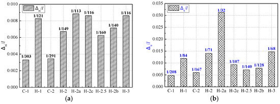
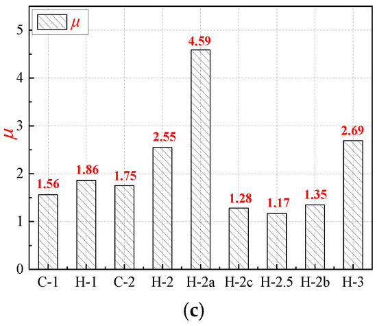
Figure 5.
Displacement factors. (a) Deflection-clear span ratio corresponding to the peak load; (b) Deflection-clear span ratio corresponding to the ultimate deflection; (c) Displacement ductility factor.
Based on Table 8 and Figure 5, the following observations can be drawn: (1) RHDC specimen H-1 had the same shear span to -effective depth ratio, and the same steel reinforcement configuration, as RC specimen C-1. Compared with specimen C-1, the deflection to clear span ratios of specimen H-1 corresponding to the peak load and ultimate deflection improved by 150% and 148%, respectively. Moreover, the displacement ductility factor was enhanced by 19.2%. This indicates that HDC can significantly improve the deformation capacity of the beams with a small span-to-depth ratio.
(2) The deflection to clear span ratios corresponding to the peak load and ultimate deflection of specimen H-2 were 95.3% and 135% higher, respectively, than the control specimen C-2. Moreover, the displacement ductility factor of specimen H-2 was 44.9% higher than specimen C-2. This demonstrates that HDC can significantly improve the deformation capacity of beams experiencing shear compression failure. For specimen H-2a, the deflection to clear span ratios corresponding to the peak load and ultimate deflection increased by 31.9% and 122%, respectively, and the displacement ductility factor was enhanced by 80% compared with that of specimen H-2. This indicates an improvement in the deformation capacity of RHDC beams with shear compression failure, achieved by the increase in the stirrup ratio owing to the effective restriction provided by the stirrups against the deformation of the beam web. Moreover, specimen H-2c exhibited lower deflection to clear span ratios corresponding to ultimate deflection and displacement ductility factor, compared with those of specimen H-2. This shows that decreasing the longitudinal reinforcement ratio was beneficial for improving the deformation ability of RHDC beams undergoing shear compression failure. Compared to specimen H-2, Specimen H-2.5 produced a smaller deflection to clear span ratio corresponding to the ultimate deflection. This demonstrates that the deformation capacity of RHDC beams decreased with the increase in the shear span to effective depth ratio under shear compression failure.
(3) Owing to the favorable tensile-strain-hardening properties and fiber-bridging effect of HDC, the HDC in the shear-tension zone continued to provide tensile stress after cracking. This effectively restrained the propagation of cracks in the flexural shear regions. Therefore, the deformation capacity of RHDC beams improved before the occurrence of major diagonal cracks. For RHDC beams with shear compression failure and flexural shear failure, the deformation capacity was significantly increased after major diagonal cracks appeared. This is because the higher ultimate compressive strain of HDC compared to that of concrete resulted in large compressive deformation in the shear-compression zone.
(4) The deflection to clear span ratios corresponding to peak load and ultimate deflection in RHDC beams were obviously higher than those in the corresponding RC beams. This can be attributed to the good tensile properties of HDC along with the strain compatibility between HDC and steel reinforcement. Furthermore, it indicates that HDC significantly improved the deformation capacity of beams with shear failure, realizing the ductile shear failure mode.
(5) The results prove that the deformation capacity of RHDC beams with shear failure depends mainly on the failure modes, which are related to the shear span to effective depth ratio, longitudinal reinforcement ratio, and stirrup ratio of the beam. RHDC beams with flexural shear failure had the best deformation capacity, followed by those with diagonal compression failure and shear compression failure; diagonal tension failure was the worst.
(6) For RHDC beams with diagonal compression failure or shear compression failure, the deformation capacity was observed to depend on the stirrup ratio, ultimate tensile strain of HDC, and ultimate compressive strain of HDC. For RHDC beams with diagonal tension failure, the deformation capacity depends mainly on the ultimate tensile strain of HDC. For RHDC beams with flexural shear failure, the deformation capacity was found to be dependent mainly on the longitudinal reinforcement ratio, stirrup ratio, ultimate tensile strain of HDC, and ultimate compressive strain of HDC.
3.5. Shear Strength
3.5.1. Shear Resistance Mechanisms
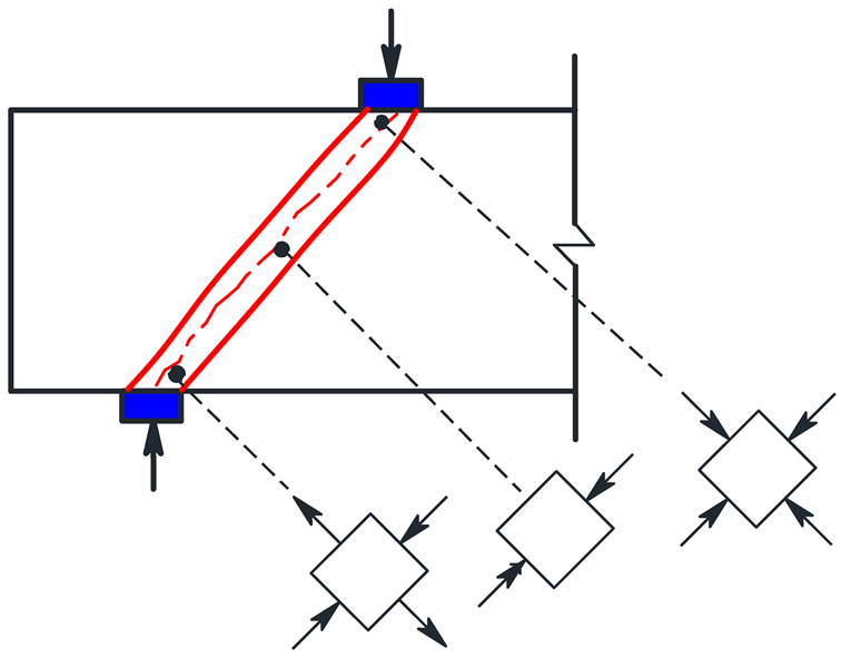
The shear resistance mechanism of an RHDC beam with stirrups can be explained using an arch–truss model, as shown in Figure 6. In the illustration, the arch closest to the support is considered the main arch I. The HDC between the diagonal cracks is the secondary arch II. The main arch I and secondary arch II act as the compressive chords of the arch–truss model. The tensile longitudinal reinforcements and stirrups act as the tension chords of the arch–truss model. After the diagonal shear crack appeared, the fiber bridging stress of HDC was equivalent to that of the diagonal tension rod. Based on the force equilibrium equation of the main arch (I), the shear strength () of RHDC beams consists of the shear resistance of stirrups (), the fiber-bridging stress of HDC in the diagonal crack section (), shear resistance of the HDC at the upper end of the diagonal crack (), and the dowel action of the longitudinal reinforcements (). The aggregate interlock force of HDC along the diagonal crack section is small because of the absence of coarse aggregates in HDC. Thus, the aggregate interlock force of HDC is not shown in Figure 6.

Figure 6.
Shear resistance mechanism of RHDC beams with stirrups: (a) arch–truss model; (b) main arch (I) and truss elements; (c) secondary arch (II) and truss elements.
3.5.2. Analysis of Shear Strength
The ratio of the peak load to the cross-sectional area of typical specimens is presented in Figure 7. The following observations can be obtained from analysis of Figure 7 and Table 8.

Figure 7.
Ratio of the peak load to the cross-sectional area.
(1) The shear strength of RHDC specimen H-1 undergoing diagonal compression failure was 45% higher than that of the corresponding RC specimen C-1, whereas the shear strength of RHDC specimen H-2 experiencing shear-compression failure was 27% higher compared with the corresponding RC specimen C-2. This indicates that HDC effectively improved the shear strength of the beam. Moreover, there was greater improvement in shear strength for the beam with diagonal compression failure.
(2) The experimental results revealed that the shear strength of RHDC beams was dependent mainly on the failure modes, which were greatly affected by the shear span to effective depth ratio and the stirrup ratio. Diagonal compression failure occurred in one case involving smaller shear span to effective depth ratio, and in another case involving proper shear span to effective depth ratio and excess stirrups. Diagonal tension failure occurred in RHDC beams with larger shear span to effective depth ratio and fewer stirrups. Shear-compression failure occurred when the beam was designed with proper shear span to effective depth ratio and moderate stirrups, or larger shear span to effective depth ratio and excess stirrups.
(3) Similar to RC beams, the shear strength of RHDC beams decreased as the shear span to effective depth ratio increased. For RHDC beams with the same shear span to effective depth ratio, the shear strength increased with the increase in the longitudinal reinforcement ratio and stirrup ratio under shear-compression failure.
(4) Before the formation of the major diagonal shear crack, when RHDC beams failed in shear, the shear strength and deformation capacity were dependent on the tensile strength and ultimate tensile strain of the HDC. For RHDC beams with diagonal compression failure, the shear strength depends on the compressive load-carrying capacity of the diagonal HDC compression struts. For RHDC beams with shear compression failure or flexural shear failure, the shear strength depends mainly on the shear compression composite strength of HDC. For RHDC beams with diagonal tension failure, the shear strength depends mainly on the tensile strength and ultimate tensile strain of HDC.
(5) Compared with RC beams, RHDC beams with shear failure exhibited larger shear cracking, yield, and peak load capacity owing to the higher tensile strength and ultimate tensile strain of HDC. This shows that HDC significantly improved the shear strength of beams with shear failure.
3.5.3. Prediction of Shear Strength According to the Code
According to the design code GB 50010-2010 [34], the shear strength of beams with stirrups under a concentrated load can be expressed by:
where is the shear span-effective depth ratio (when , consider 1.5, when , consider 3); is the tensile strength of concrete; b is the section width of the beam; is the effective depth of the beam; is the yield strength of the stirrup; and s is the spacing of the stirrup.
Table 9 lists the experimental values () and calculated values () of the shear strength of 15 beam specimens. Based on Table 9, the following observations can be obtained:
Table 9.
Comparison of experimental and calculated shear strength values.
(1) For RC beams with diagonal compression failure, the shear strength depends on the compressive strength of concrete. To avoid brittle diagonal compression failure of RC beams, the calculated value of shear strength, according to GB 50010-2010, was conservative.
(2) For RHDC beams with diagonal compression failure, shear strength depends on the compressive load-carrying capacity of the diagonal HDC compression struts. The calculated value of shear strength should be increased appropriately owing to the better ductility of RHDC beams. According to GB 50010-2010, the predicted value of shear strength of RHDC beams improves because the tensile strength of HDC is approximately 1.52 times that of concrete. However, the calculated shear strength values of RHDC beams remained conservative compared to the experimental values.
(3) The favorable tensile-strain-hardening characteristics and multiple cracking mechanisms of HDC improved significantly the brittle shear failure mode of RC beams. The shear strength of RHDC beams is closely related to the ultimate tensile strain and ultimate compressive strain of HDC. In this test, the ultimate tensile strain and ultimate compressive strain of HDC were found to be much higher compared to those of concrete. Meanwhile, the experimental values of the shear strength of RHDC beams were distinctly higher than the calculated values. Therefore, the influence of material ductility should be considered while predicting the shear strength of RHDC beams.
4. Conclusions
In this study, 15 beam specimens involving two materials (concrete and HDC) were analyzed to investigate their shear behavior under a concentrated load. The experimental parameters included the shear span to effective depth ratio, stirrup ratio, and longitudinal reinforcement ratio. The focus was on crack patterns, failure mode, load–deflection behavior, deformation capacity, and shear strength. The following conclusions can be obtained based on the results of this study.
- Unlike RC beams, RHDC beams failed in the shear mode with a gradual decrease in load-carrying capacity and higher residual strength. The modes of failure of RHDC beams included diagonal compression, shear-compression, flexural shear, and diagonal tension failures. When the shear span to effective depth ration was three, some RHDC beams failed in flexural shear mode with favorable ductility.
- Compared with RC beams, RHDC beams exhibited satisfactory integrity without the collapse and peeling-off of HDC. Stable crack propagation and multiple diagonal crack behavior were observed in RHDC beams, indicating that the fiber-bridging effect of HDC effectively restrained the development of shear cracks.
- Improvements in shear strength of RHDC beams ranged from 13.3% to 30.5% compared with RC beams; RHDC beams exhibited higher residual strength and deformation capacity, indicating that HDC significantly improved the brittle shear failure mode. Specimens H-1 and H-2 exhibited the largest improvement in shear strength and displacement ductility factor, respectively, compared with RC beams.
- The results proved that the shear span to effective depth ratio, stirrup ratio, and longitudinal reinforcement ratio of RHDC beams had a great influence on the shear failure modes. The shear strength of RHDC beams decreased as the shear span to effective depth ratio increased. For RHDC beams with the same shear span to effective depth ratio, the shear strength increased with the increase in longitudinal reinforcement ratio and stirrup ratio under shear compression failure.
- The calculated value of shear strength, according to GB 50010-2010, is conservative compared to the experimental values for shear strength of RHDC beams. The effect of material ductility on the shear strength of RHDC beams needs to be studied further, because shear failure modes and shear strength are closely related to the ultimate tensile strain and ultimate compressive strain of HDC.
Author Contributions
Conceptualization, M.Z. and M.D.; methodology, M.Z.; software, M.Z. and J.Y.; validation, M.Z., M.D. and Y.Z.; formal analysis, M.Z.; investigation, M.Z.; resources, M.D.; data curation, M.Z.; writing—original draft preparation, M.Z.; writing—review and editing, M.Z., J.Y. and Y.Z.; visualization, M.Z.; supervision, M.Z. and M.D.; project administration, M.D.; funding acquisition, M.D. All authors have read and agreed to the published version of the manuscript.
Funding
This research was funded by Xi’an Science and technology innovation project, grant number 20191522415KYPT015JC017. The APC was funded by Xi’an Science and technology innovation project, grant number 20191522415KYPT015JC017.
Institutional Review Board Statement
Not applicable.
Informed Consent Statement
Not applicable.
Data Availability Statement
Not applicable.
Conflicts of Interest
The authors declare no conflict of interest.
References
- Deng, M.; Han, J.; Liu, H.; Qin, M.; Liang, X. Analysis of Compressive Toughness and Deformability of High Ductile Fiber Reinforced Concrete. Adv. Mater. Sci. Eng. 2015, 3, 1–7. [Google Scholar] [CrossRef]
- Li, V.C.; Wang, S.; Wu, C. Tensile strain-hardening behavior of polyvinyl alcohol engineered cementitious composite (PVA-ECC). ACI Mater. J. 2001, 98, 483–492. [Google Scholar]
- Li, V.C. Engineered cementitious composites (ECC)-a review of the material and its applications. J. Adv. Concr. Technol. 2003, 1, 215–230. [Google Scholar] [CrossRef]
- Mechtcherine, V.; de Andrade Silva, F.; Butler, M.; Zhu, D.; Mobasher, B.; Gao, S.-L.; Mäder, E. Behavior of strain-hardening cement based composites under high strain rates. J. Adv. Concr. Technol. 2011, 9, 51–62. [Google Scholar] [CrossRef]
- Naaman, A.E. High-Performance Construction Materials: Science and Applications; World Scientific Publishing: Singapore, 2008; pp. 91–153. [Google Scholar]
- Reinhardt, H.W.; Naaman, A.E. High Performance Fiber Reinforced Cement Composites (HPFRCC3); RILEM Publications: Mainz, Germany, 1999; pp. 371–385. [Google Scholar]
- Parramontesinos, G.J. High-performance fiber-reinforced cement composites: An alternative for seismic design of structures. ACI Struct. J. 2005, 102, 668–675. [Google Scholar]
- Kobayashi, K.; Ahn, D.L.; Rokugo, K. Effects of crack properties and water-cement ratio on the chloride proofing performance of cracked SHCC suffering from chloride attack. Cem. Concr. Compos. 2016, 69, 18–27. [Google Scholar] [CrossRef]
- Curosu, I.; Mechtcherine, V.; Forni, D.; Cadoni, E. Performance of various strain-hardening cement-based composites (SHCC) subject to uniaxial impact tensile loading. Cem. Concr. Res. 2017, 102, 16–28. [Google Scholar] [CrossRef]
- Zhou, J.; Pan, J.; Leung, C.K.Y. Mechanical Behavior of Fiber-Reinforced Engineered Cementitious Composites in Uniaxial Compression. J. Mater. Civ. Eng. 2014, 17, 04014111. [Google Scholar] [CrossRef]
- Yoo, D.-Y.; Yang, J.-M. Effects of stirrup, steel fiber, and beam size on shear behavior of high-strength concrete beams. Cem. Concr. Compos. 2018, 87, 137–148. [Google Scholar] [CrossRef]
- Kachouh, N.; El-Maaddawy, T.; El-Hassan, H.; El-Ariss, B. Shear Behavior of Steel-Fiber-Reinforced Recycled Aggregate Concrete Deep Beams. Buildings 2021, 11, 423. [Google Scholar] [CrossRef]
- Yuan, F.; Pan, J.; Dong, L.; Leung, C.K.Y. Mechanical Behaviors of Steel Reinforced ECC or ECC/Concrete Composite Beams under Reversed Cyclic Loading. J. Mater. Civ. Eng. 2013, 26, 04014047. [Google Scholar] [CrossRef]
- Majdzadeh, F.; Soleimani, S.M.; Banthia, N. Shear strength of reinforced concrete beams with a fiber concrete matrix. Can. J. Civ. Eng. 2006, 33, 726–734. [Google Scholar] [CrossRef]
- Altoubat, S.; Yazdanbakhsh, A.; Rieder, K.-A. Shear behavior of macro-synthetic fiber-reinforced concrete beams without stirrups. ACI Mater. J. 2009, 106, 381–389. [Google Scholar]
- Choi, K.-K.; Park, H.-G.; Wight, J.K. Shear Strength of Steel Fiber-Reinforced Concrete Beams without Web Reinforcement. ACI Struct. J. 2007, 104, 12–21. [Google Scholar] [CrossRef]
- Xu, S.; Hou, L.-J.; Zhang, X.-F. Shear Behavior of Reinforced Ultrahigh Toughness Cementitious Composite Beams without Transverse Reinforcement. J. Mater. Civ. Eng. 2012, 24, 1283–1294. [Google Scholar] [CrossRef]
- Alrefaei, Y.; Rahal, K.; Maalej, M. Shear Strength of Beams Made Using Hybrid Fiber–Engineered Cementitious Composites. J. Struct. Eng. 2018, 144, 04017177. [Google Scholar] [CrossRef]
- Paegle, I.; Fischer, G. Phenomenological interpretation of the shear behavior of reinforced Engineered Cementitious Composite beams. Cem. Concr. Compos. 2016, 73, 213–225. [Google Scholar] [CrossRef]
- Hossain, K.M.A.; Hasib, S.; Manzur, T. Shear behavior of novel hybrid composite beams made of self-consolidating concrete and engineered cementitious composites. Eng. Struc. 2020, 202, 109856. [Google Scholar] [CrossRef]
- Hou, L.-J.; Xu, S.; Zhang, X.-F.; Chen, D. Shear Behaviors of Reinforced Ultrahigh Toughness Cementitious Composite Slender Beams with Stirrups. J. Mater. Civ. Eng. 2014, 26, 466–475. [Google Scholar] [CrossRef]
- Deng, M.; Dai, J.; Lu, H.; Liang, X. Shear Capacity and Failure Behavior of Steel-Reinforced High Ductile Concrete Beams. Adv. Mater. Sci. Eng. 2015, 2015, 1–8. [Google Scholar] [CrossRef]
- Deng, M.; Ma, F.; Ye, W.; Liang, X. Investigation of the shear strength of HDC deep beams based on a modified direct strut-and-tie model. Constr. Build. Mater. 2018, 172, 340–348. [Google Scholar] [CrossRef]
- Deng, M.; Ma, F.; Wang, X.; Lü, H. Investigation on the shear behavior of steel reinforced NC/HDC continuous deep beam. Structures 2019, 23, 20–25. [Google Scholar] [CrossRef]
- Deng, M.; Zhang, Y. Seismic Performance of High-Ductile Fiber-Reinforced Concrete Short Columns. Adv. Civ. Eng. 2018, 2018, 1–11. [Google Scholar] [CrossRef]
- Zhang, Y.; Deng, M.; Dong, Z. Seismic response and shear mechanism of engineered cementitious composite (ECC) short columns. Eng. Struct. 2019, 192, 296–304. [Google Scholar] [CrossRef]
- Liang, X.; Lu, T. Seismic evaluation of engineered cementitious composites beam-column-slab subassemblies with various column-to-beam flexural strength ratios. Struct. Concr. 2017, 19, 735–746. [Google Scholar] [CrossRef]
- Deng, M.; Ma, F.; Song, S.; Lü, H.; Sun, H. Seismic performance of interior precast concrete beam-column connections with highly ductile fiber-reinforced concrete in the critical cast-in-place regions. Eng. Struct. 2020, 210, 110360. [Google Scholar] [CrossRef]
- Said, S.H.; Razak, H.A. Structural behavior of RC engineered cementitious composite (ECC) exterior beam–column joints under reversed cyclic loading. Constr. Build. Mater. 2016, 107, 226–234. [Google Scholar] [CrossRef]
- Xu, L.; Pan, J.; Lu, C.; Yin, W. Development mechanism of plastic hinge in reinforced engineered cementitious composite beams under monotonic loading. Struct. Concr. 2018, 20, 252–266. [Google Scholar] [CrossRef]
- Said, M.; Montaser, W.; Elgammal, A.S.; Zahir, A.H.; Shaaban, I.G. Shear strength of reinforced mortar beams containing pol-yvinyl alcohol fibre (PVA). Int. J. Civ. Eng. 2021, 19, 1155–1178. [Google Scholar] [CrossRef]
- Meng, D.; Lee, C.K.; Zhang, Y.X. Flexural and shear behaviours of plain and reinforced polyvinyl alcohol-engineered cementitious composite beams. Eng. Struct. 2017, 151, 261–272. [Google Scholar] [CrossRef]
- JGJ 55; Specification for Mix Proportion Design of Ordinary Concrete. Chinese Building Industry Press: Beijing, China, 2011. (In Chinese)
- GB 50010; Code for Design of Concrete Structures. Chinese Standard Press: Beijing, China, 2010. (In Chinese)
- GB/T 50152; Standard for Test Method of Concrete Structures. Chinese Architecture & Building Press: Beijing, China, 2012. (In Chinese)
- Mahin, S.A.; Bertero, V.V. An Evaluation of Inelastic Seismic Design Spectra. J. Struct. Div. 1981, 107, 1777–1795. [Google Scholar] [CrossRef]
- Hosen, A.; Althoey, F.; Jumaat, M.; Alengaram, U.; Sulong, N. Flexural Performance of RC Beams Strengthened with Externally-Side Bonded Reinforcement (E-SBR) Technique Using CFRP Composites. Materials 2021, 14, 2809. [Google Scholar] [CrossRef] [PubMed]
- DBJ61/T112; Technical Specification for Application of High Ductile Concrete. China Building Materials Press: Xi’an, China, 2016.
- JSCE. Recommendations for Design and Construction of High-Performance Fiber-Reinforced Cement Composites with Multiple Fine Cracks (HPFRCC); Japan Society of Civil Engineers: Tokyo, Japan, 2008. [Google Scholar]

Publisher’s Note: MDPI stays neutral with regard to jurisdictional claims in published maps and institutional affiliations. |
© 2022 by the authors. Licensee MDPI, Basel, Switzerland. This article is an open access article distributed under the terms and conditions of the Creative Commons Attribution (CC BY) license (https://creativecommons.org/licenses/by/4.0/).