Abstract
A simplified analytical solution for steel plate strengthened circular tunnel concrete linings is presented, considering various interface slip modes. The full derivation for the analytical solution is introduced in detail, from which explicit expressions for the stress and displacement fields throughout the system are obtained. The distribution of lining deformation, internal force, and the interaction stress between tunnel lining and steel plate were investigated by considering various tunnel-steel interface scenarios, namely no slip, full slip, and elastic slip. The result demonstrates the importance of having a well-bonded interface to maximize the benefits of the steel plate strengthening approach. The maximum interface shear stress locates at the position with minimum interface normal stress. Subsequently, the influence of interface shear stiffness and steel plate thickness on the composited tunnel lining performance was investigated. It is founded that the improvement of the interface shear stiffness can enhance the overall structural stiffness of the strengthened tunnel lining, which results in increases in the interaction stresses and lining forces simultaneously. With a ratio of the steel thickness to the tunnel lining thickness less than 0.1, greater achievement in both strengthening effectiveness and cost efficiency is obtained.
1. Introduction
Due to an increasing development associated with underground space in many large cities around the world, tunnels are playing an increasingly significant role in urban infrastructure systems. Many tunnels in urban areas are often constructed close to other engineering constructions, and hence their lining performance is potentially very sensitive to changes in the surrounding ground conditions or loading conditions. There are several reported cases where operational tunnels were strongly affected by nearby engineering activities or accidents, for example, adjacent excavations [1], ground surface surcharging [2], flooding [3], and penetration by piles [4]. In these cases, the tunnel lining was extensively deformed, and various defects were observed, e.g., water leakage and concrete crack [5,6], which threatened the safety of the tunnel operation. Therefore, having quick and effective repair treatments or rehabilitation measures is of great importance to ensure the safety and durability of existing tunnel linings affected by such accidents.
Installing a steel plate lining into the existing tunnel has been successfully adopted as a retrofitting measure in many engineering situations for tunnel rehabilitation worldwide due to its effectiveness in strengthening the existing tunnel linings, its space efficiency, and its quick construction. The main phases of this method can be summarized as follows. First, the steel plates are manufactured according to the inner profile of the tunnel, needed to be strengthened. Second, the steel plate sections are installed and welded to form an inner steel ring connected to the existing tunnel linings. Third, the gap between the new steel plate lining and the original concrete lining is filled with mortar or epoxy resin to ensure the two components behave as a composite lining structure. In this way, the increasing lining deformation is controlled, and the capacity of the tunnel structure can be enhanced [7]. Although this strengthening method has been implemented in practice, no specific methodology can be referred to for the design of this tunnel strengthening method. In addition, the lack of knowledge of the interaction mechanism between the tunnel lining and steel plates could still be leading to over-conservative applications.
In order to investigate the strengthening mechanism of this method and to provide advice for the engineers, research has been conducted to study the performance of tunnel linings strengthened by steel plates. Kiriyama et al. [8] introduced a detailed construction process for the steel plate reinforcement method in different types of tunnels. Zhao et al. [9] conducted a full-scaled load structure test on a concrete segmental tunnel lining ring reinforced with epoxy-bonded steel plates. The results showed that the stiffness of the segmental ring was significantly improved after being strengthened by the steel plates. Simplified beam element models were adopted in their analysis of the structural performance of the lining strengthened by steel plates, where the ground-lining interaction was either neglected or replaced by springs based on the Winkler model. Zhang et al. [10] investigated the nonlinear structural performance of segmental lining strengthened by steel plates using finite element numerical simulations, with the ground-lining and lining-steel interaction considered and the influence of the soil properties discussed. It can be summarized that the strengthening effect of this steel plate reinforcement method has been proved sufficiently from a general perspective in previous research. The previous studies containing numerical and physical modelling provide an understanding of strengthening effectiveness on a case-by-case basis. However, there is still a lack of clear insight into the strengthening mechanism in terms of parameters associated with the interaction between the concrete lining and the steel plate. More specifically, there is a lack of research demonstrating the patterns of the interaction forces at the interfaces between the components and how much of the internal forces in the steel plates really share within the lining system.
Although powerful numerical simulations can handle such issues these days, a theoretical analysis can still serve as a useful and effective methodology for simplifying such problems and allowing a quick, explicit, and simple parametric investigation to be conducted not only for researchers but also for engineers [11]. Furthermore, analytical solutions can provide a greater fundamental understanding of the essential issues for complicated engineering problems, which can be helpful in identifying aspects for more comprehensive research [12]. Thus, a closed-form analytical solution for circular tunnels strengthened by steel plates is required and would be of great value.
Abundant research has been conducted into analytical solutions for determining the stress and displacement fields associated with circular tunnel linings using the stress function method. Wood [13] and Morgan [14] proposed a method to calculate the internal forces of buried circular tunnel lining with an elliptical deformation mode. Einstein and Schwartz [15] presented a simplified analytical solution for a general circular tunnel, which was expanded by Bobet [16] to calculate tunnels under saturated ground conditions. Based on a similar methodology, much research has been conducted to predict the ground movement patterns due to the existence of tunnel linings [17,18,19]. Soil plasticity is also considered in many other ground movement prediction models [20,21]. There are some studies on analytical solutions for tunnels with double linings. Mason and Abelman [22] studied a two liners system circular tunnel, which was subjected to shear stress at infinity. El Naggar et al. [23,24] presented a closed-form analytical solution for a composite lining of a circular tunnel in deep burial conditions, where the stress and displacement results of double-layered circular tunnel lining were presented based on the theory of thick-wall cylinders. In the previous theoretical analysis for composite tunnel linings based on the theory of thick-walled cylinders, the interface between separate liners could only be considered as ideal scenarios, namely full-slip and no-slip [25]. In terms of the full-slip condition, the outer and inner linings are assumed to be frictionless; thus, relative displacement between two liners could happen without restriction along the interface. In terms of the no-slip condition, the outer and inner linings are assumed to be perfectly connected, thus no relative displacement would occur. Although it is sometimes reasonable to simplify the interface as full-slip or no-slip scenarios, the actual interface behavior is always somewhere between these two ideal conditions. For the steel strengthened tunnel problem discussed in this paper, the steel plate is bonded to the concrete lining by a layer of epoxy adhesive. The interface slippage between the tunnel lining and steel plate will happen at the adhesive when they deform as a composite lining system. However, the existing analytical solutions based on the theory of thick-walled cylinders are not able to well capture the interface slippage between the tunnel lining and steel plate because the interaction mechanism is only considered as either no-slip or full-slip scenarios.
In using different aspects of the previous research, this paper focuses on an analytical solution for a circular tunnel strengthened by a steel plate, considering the interface slippage between the concrete lining and the steel plate. Initially, an analytical model in a polar coordinate system is established for this problem, containing three objects, i.e., the ground, the circular concrete lining, and the steel plate. Subsequently, analytical solutions for the stress and displacement distributions are derived for each object with the interaction stress components treated as unknown variables, where the concrete-steel interface slippage is considered by introducing an interface shear stiffness coefficient. Finally, the unknown interaction stresses are solved by implying the interface compatibility conditions. The distribution of internal forces and the interaction stresses are illustrated using a case study using the proposed analytical solution. Based on this, the effectiveness of, and the mechanisms associated with, the steel plate reinforcement, including the influence of the essential factors, i.e., interface shear stiffness and steel plate thickness, are further investigated and discussed. The main contribution of this work is to present the analytical solutions with consideration of various interface slip modes by introducing an interface stiffness coefficient kcs. The explicit analytical solutions for the stress and displacement components of steel strengthened tunnel lining are derived, with interface interaction property described by coefficient kcs. The simplified analytical solutions proposed in this paper are intended to bridge the gap between two ideal interface conditions for a better understanding of the composite lining behaviour of the steel plate strengthened tunnels.
2. Analytical Solutions
2.1. Problem Illustration
Figure 1 presents the typical tunnel strengthening problem discussed in this paper. There has been an existing circular tunnel with concrete lining thickness tc and external radius R1. In order to achieve higher lining performance, a steel plate with thickness ts is installed inside the existing tunnel. As shown in Figure 2, a thin layer of cohesive material like epoxy resin is used to fill the gap between the concrete lining and the steel plate, so they behave as a composited tunnel supporting system.
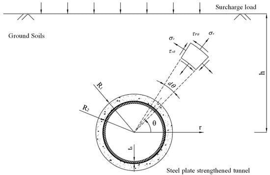
Figure 1.
A sketch of a steel plate strengthened circular tunnel.
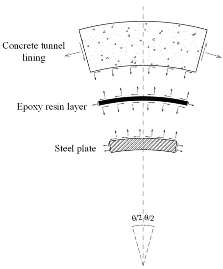
Figure 2.
The interaction mechanism of steel plate strengthened concrete tunnel lining.
A polar coordinate with the origin at the centre of the circular tunnel is used. The plane strain condition with the longitudinal direction perpendicular to the tunnel cross section is adopted. In addition to the fundamental assumptions in the theory of elasticity, some additional key assumptions in this research are listed as follows:
- The aim of this paper is to investigate the interaction mechanism of concrete lining strengthened by steel plate; therefore, the stress and deformation within the ground soil and concrete lining before strengthening are not considered.
- The tunnel depth is much larger than the tunnel diameter, so the influence of the ground surface free boundary is ignored.
- The epoxy resin layer is treated as zero thickness.
- During tunnel construction (e.g., mechanized shield-driven tunnelling), a dense layer of compensation cement grout exists between the tunnel lining and the ground. Therefore, it is assumed that no relative displacement happens between the concrete lining and the ground soil after strengthening.
To obtain the stress and displacement of the strengthened tunnel, the model is decomposed into three components, i.e., the ground, the concrete lining, and the steel plate, respectively, as shown in Figure 3. The ground has been treated as an infinite elastic plane with a circular hole. The vertical load Pv and horizontal load Ph are applied at far field boundaries to simulate the influence of surcharge load after the strengthening. There exists an interaction between normal stress and shear stress between the ground soil and the concrete lining. The tunnel lining has been treated as a cylinder with a thickness of tc, and the steel plate has been treated as a cylinder with a thickness of ts. There exists an interaction between normal stress and shear stress at the concrete–steel interface. The internal surface of the steel plate is free of stress. For the ground, concrete lining, and steel plate, given the boundary conditions, the stress and displacement components for all three objects can be derived in terms of interaction stress components using the Airy function method.

Figure 3.
Decomposed model in terms of the ground, the concrete lining, and the steel plate.
2.2. Stress and Displacement of the Ground Soil
As shown in Figure 4a, the ground soil with a circular tunnel excavation is subjected to far field stress Pv = −P and Ph = −kP, where P is the surcharge load and k is the earth pressure coefficient. It is considered equivalent to the superposition of a hydrostatic condition and a deviatoric condition, as shown in Figure 4b,c, respectively.
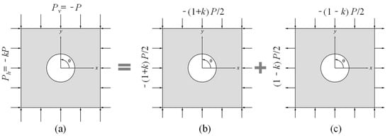
Figure 4.
Illustration for ground soil with circular tunnel excavation. (a) Superposition; (b) Hydrostatic condition; (c) Deviatoric condition.
According to Timoshenko [26], the stress function for the hydrostatic condition, as shown in Figure 4b, is expressed as:
where and are constants. Using this stress function, the stress components within the ground are:
The stress at the far field is effectively the same as that in the plate without a tunnel, and therefore is given by:
By substituting Equations (2)–(4) into Equation (5), it gives: . Therefore, the stress function for the ground soil in the hydrostatic condition is:
The stress function for the ground soil in deviatoric condition, as shown in Figure 4c, is expressed as:
where , , , and are constants. Using this stress function, the stress components of the ground are:
The stresses at far field are effectively the same as those in the ground without a tunnel, and therefore are given by:
By substituting Equations (8)–(10) into Equations (11) and (12), it becomes and . Thus, the stress function for the ground soil in the deviatoric condition is:
The stress function for both the hydrostatic and deviatoric conditions have been obtained. By combining Equations (7) and (13), the stress function for the ground soil with a circular tunnel, as shown in Figure 4a, is given by:
where , , and are constants to be solved.
From the derivatives of Equation (14), the stress components in the ground soil are:
Using Hooke’s law in the plane strain condition, the strain components in the ground are:
By integration of Equation (11), the displacement components in the ground are:
where and are ground soil movement in radial and circumferential directions, is the elastic modulus of ground, is the Poisson’s ratio of the ground, and , , and are constants to be solved according to boundary conditions. The boundary of the ground soil at the tunnel opening r = R1 are considered, where the soil is subjected to interactions from the concrete lining. The ground soil stress components at the tunnel lining boundary are:
where, and are the interaction normal and shear stress between the ground soil and the concrete lining. By substituting Equation (18) into Equation (19), the constants, i.e., , , and , within above equations are solved:
Therefore, by substituting Equations (24)–(26) into Equations (12), (15)–(17), (20) and (21), the stress and displacement components in the ground are obtained, with the unknown variables as the interaction stress, i.e., and , between the ground and concrete tunnel lining.
2.3. Stress and Displacement of the Concrete Lining
As shown in Figure 5, the tunnel concrete lining is modelled as a cylinder with lining thickness tc. The external radius of the concrete lining is R1, where the tunnel is subjected to the normal and shear interactions from the ground. The internal radius of the concrete lining is R2, where the tunnel is subjected to the normal and shear interactions from the strengthening steel plate. The stress function for such a thick-walled cylinder is:
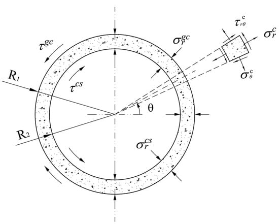
Figure 5.
An illustration of stress condition in the concrete tunnel lining.
The stress components within the concrete lining are given by:
Using Hooke’s law in the plane strain condition, the strain components in the concrete tunnel lining are:
By integration of Equations (31) and (32), the displacement components are obtained:
where and are concrete lining displacement in the radial and circumferential directions, is the elastic modulus of the concrete lining, is the Poisson’s ratio of the concrete lining, and , , , , and are constants to be solved according to the boundary conditions. The boundaries of the concrete tunnel lining at r = R2 and r = R3 are considered, where the concrete lining is subjected to the interaction stresses from the ground and the steel plate, respectively. The stress components of the concrete lining at r = R1 are given by:
The stress components at r = R2 are given by:
where, and are the interactions between normal and shear stress between the ground soil and the concrete lining, and and are the interaction normal and shear stress between the concrete lining and the steel plate. By substituting Equations (28)–(30) into Equations (35)–(38), the constants, i.e., , , , , and , are solved:
Therefore, by substituting Equations (39)–(44) into Equations (28)–(30), (33) and (34), the stress and displacement components are derived with the unknown variables as interaction stresses, i.e., , , , and .
2.4. Stress and Displacement of the Steel Plate
As shown in Figure 6, the steel plate is modelled as a cylinder with thickness ts. The external radius of the steel plate is R2, where the steel plate is subjected to the normal and shear interactions from the concrete lining. The internal radius of the steel plate is R3, where the steel plate surface is free from stress. The stress function for the steel plate cylinder is:
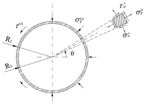
Figure 6.
An illustration of stress condition in the steel plate.
The stress components within the steel plate are:
Using Hooke’s law in the plane strain condition, the strain components in the steel plate are:
By integration of Equations (49) and (50), the displacement components are obtained:
where and are steel plate displacement in radial and circumferential directions, is the elastic modulus of the steel plate, is the Poisson’s ratio of the steel plate, and , , , , , and are the constants to be solved according to the boundary conditions. Boundaries of the steel plate at r = R2 and r = R3 are considered. The steel plate is subjected to the interaction stress from the concrete lining at r = R2, where the stress components are given by:
The internal surface of the steel plate is free of stress. Thus, the stress components of the steel plate at r = R3 are given by:
where, and are the interaction normal and shear stress between the concrete lining and the steel plate. By substituting Equations (46)–(48) into Equations (53)–(56), the constants, i.e., , , , , , and , are solved:
Therefore, by substituting Equations (57)–(62) into Equations (46)–(48), (51) and (52), the stress and displacement components are derived with the unknown variables as interaction stresses, i.e., and .
2.5. Interface Compatibility Conditions
The stress and displacement components in all three objects have been obtained. To solve the unknow interaction stresses, compatibility conditions at the ground-tunnel interface and concrete-steel interface are needed. According to the fourth assumption in the proposed model, no relative displacement occurs between the ground and the tunnel lining. Thus, the compatibility demand at r = R1 is given by:
The interface property between the concrete lining and the steel plate is key to the strengthened tunnel behavior. Three different interface conditions are considered in this research, i.e., full-slip, no-slip, and bond-slip conditions. In terms of the no-slip condition, the concrete lining and the steel plate are perfectly combined, and no relative displacement occurs at the interface. This refers to the situation when the steel plate is very strongly connected to the concrete lining. The compatibility at the concrete-steel interface (r = R2) is:
In terms of the full-slip condition, the interface between the concrete lining and steel plate is free of shear stress and constrained in the radial displacement. This refers to the situation when the concrete-steel interface is fully deboned and a strengthening failure has occurred. The stress and compatibility demand for the full-slip interface condition is:
In terms of the bond-slip condition, bond-slip is considered at the interface between the concrete lining and the steel plate. In this study, the interface shear stress is considered proportional to the difference in circumferential displacement between the concrete lining and steel plate. An interface shear stiffness coefficient is proposed to indicate the property of the concrete-steel bonding interface. Thus, the stress and compatibility demand for the bond-slip condition is given by:
where, is the shear stiffness coefficient of the concrete-steel interface. The value of will be investigated in this study.
By substituting the stress and displacement components of the ground, the concrete tunnel lining and the steel plate into the compatibility equations corresponding to the different interface conditions, the unknown interaction stresses, , , , and can then be solved. Therefore, all stress and displacement values are obtained.
3. Validation of The Proposed Analytical Solutions
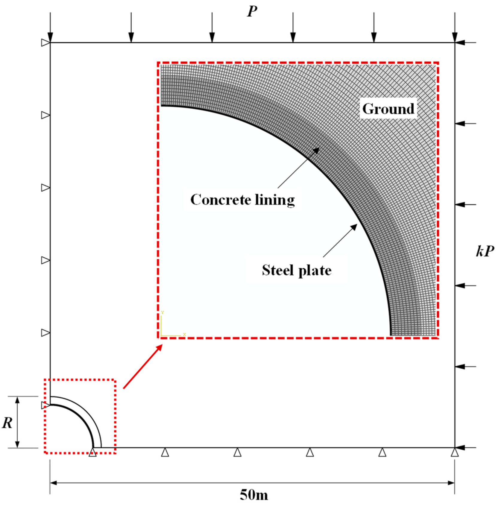
To validate the rationale and accuracy of the proposed analytical solutions, a finite element (FE) analysis was conducted to simulate the circular tunnel strengthened by a steel plate. The analysis was executed using the commercial FE package ABAUQS. To simultaneously achieve a good calculation accuracy and a high computational efficiency for such a symmetric problem, a quarter plane model is adopted, the mesh of which is shown in Figure 7. It contains three components, the ground, a tunnel lining, and a steel plate with 20576 four-node plane strain (CPE4) elements in total. All the materials are taken as elastic, and the parameters listed in Table 1 are adopted. The left vertical boundary of the ground is fixed in the X direction, while the bottom boundary is fixed in the Y direction. The width and the height of the half ground model are 50 m which is over 10 R, so the effect of the boundary could be neglected. The ground stress caused by the surcharge load is simulated by applying vertical load P on the top and horizontal load on the right.
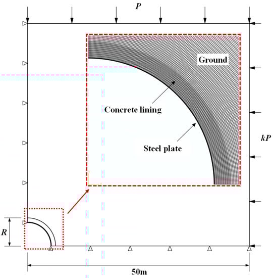
Figure 7.
Finite element mesh for circular tunnel strengthened by steel plate.

Table 1.
Parameters of each material in the proposed model.
The interface between the ground and the tunnel lining is simulated using contact pairs, with the interaction property adopted as “Hard” contact in the normal direction and “Rough” in the tangential direction. Thus, no relative displacement is allowed between two components, which is identical to the proposed analytical model. The interface between the tunnel lining and the steel plate is simulated by using contact pairs. “Hard” contact property is given in the normal direction, while “Rough” or “frictionless” contact properties are given in the tangential direction to simulate no-slip and full-slip interface conditions, respectively.
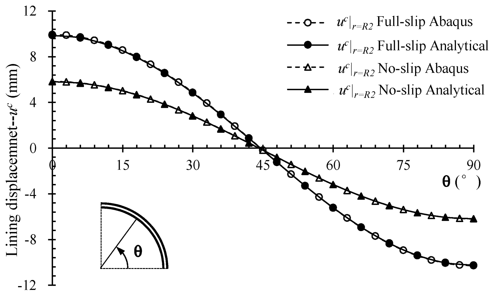
Figure 8 presents the comparison of the lining displacement evaluated by the Abaqus FE model and the analytical model proposed in this study. The tunnel deformations calculated by the two models agree well with each other in both full-slip and no-slip interface conditions. The tunnel deforms elliptically, with the lining inward motion occurring at the tunnel crown and outward motion occurring at the tunnel spring line. The maximum lining displacements calculated by the analytical and the FE model are −10.25 mm and −10.30 mm at the tunnel crown (θ = 90°), respectively. The largest difference in lining displacement given by the Abaqus FE model and the proposed analytical solution is 0.5%.
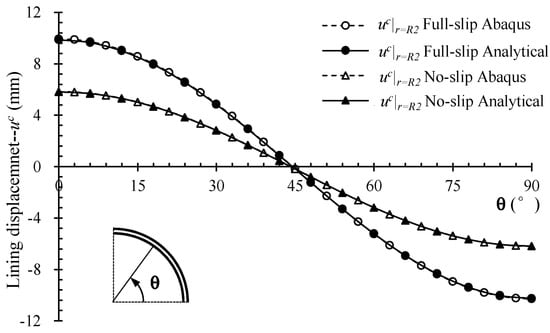
Figure 8.
Comparison of the lining displacement evaluated by FE and analytical solutions with different concrete-steel interface properties.
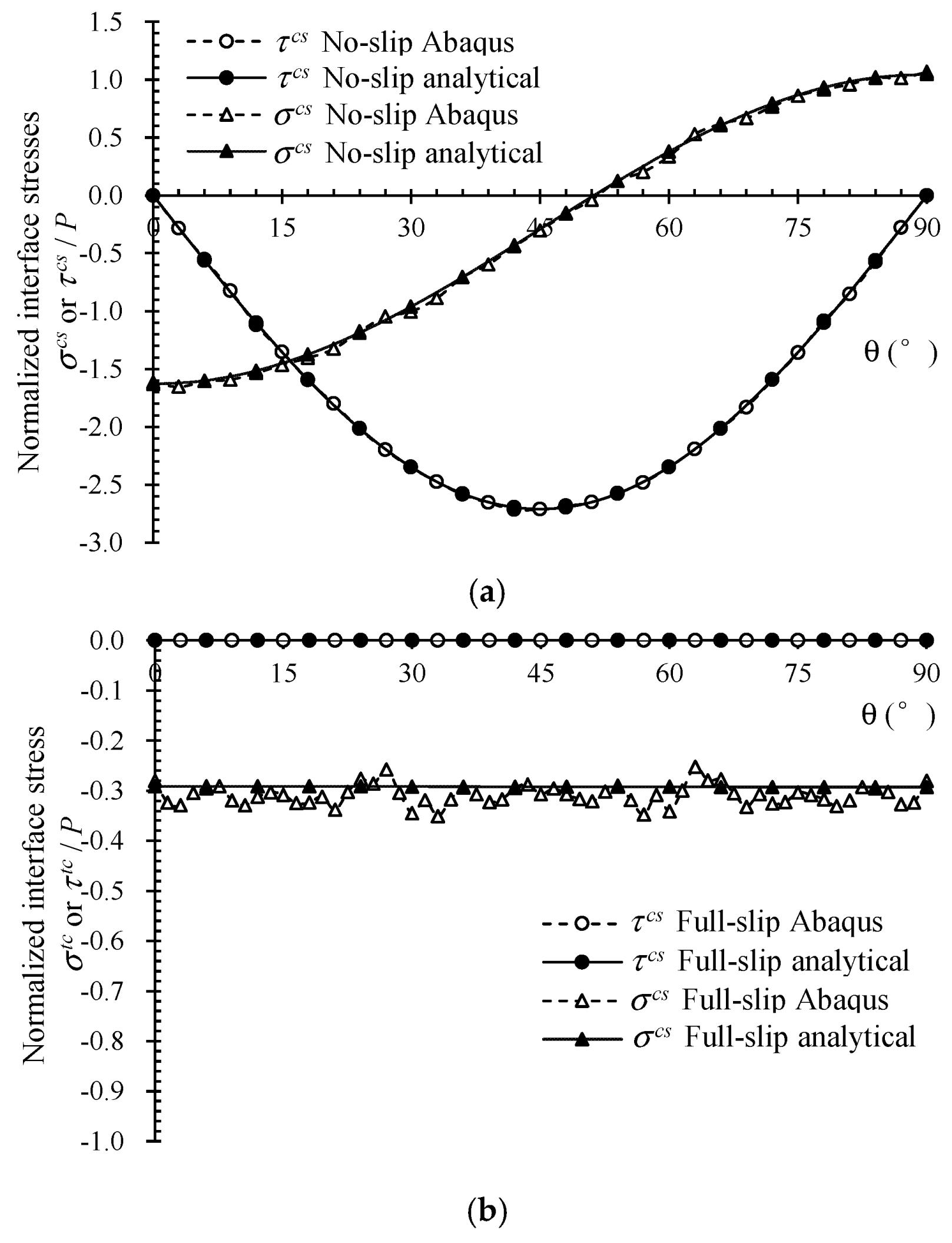
Figure 9 compares interface stresses evaluated by FE and the proposed analytical solutions. Figure 9a shows results from the steel plate strengthened tunnel with the no-slip concrete-steel interface. It was observed that the interface normal and shear stress evaluated by the two models agree well with each other. The interface normal stress between the concrete lining and steel plate is compression from 0° to 51°, while it is tension from 51° to 90°. The maximum interface tension and compression stress appear at the location of the tunnel spring line (θ = 0°) and crown (θ = 90°), respectively. The largest difference in the interface normal stress evaluated by the analytical and FE method is 2%. The maximum interface shear stress appears at θ = 45°, where the difference in the shear stress values evaluated by the two methods is 0.08%.
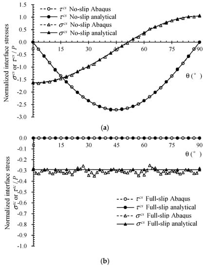
Figure 9.
Comparison of the interface stresses evaluated by FE and analytical solutions with different concrete-steel interface properties. (a) Concrete-steel interface property: no-slip; (b) Concrete-steel interface property: full-slip.
Figure 9b shows the result of the steel plate strengthened tunnel with the full-slip concrete-steel interface. It is observed that the interface normal and shear stress evaluated by the two models agree well with each other. The interface normal stress between the concrete lining and steel plate is compression, while no shear stress exists.
From the above comparisons between the lining displacement and interface stress evaluated by the FE approach and analytical solutions, it is proved that the analytical solution proposed in this paper is able to provide results with good accuracy. Obviously, the proposed analytical solution is much easier and quicker to use.
4. Analysis of Steel Plate Strengthening Effectiveness
In this section, in order to investigate the strengthening mechanism, the structural performance of tunnels with and without steel plate strengthening was analyzed and compared using the proposed analytical solutions. First, the interface shear stiffness coefficient was determined based on the shearing test study on the concrete-steel bonded joint from the literature. Subsequently, using the analytical solutions proposed in this paper, tunnels with and without steel plate strengthening were analyzed. By comparing the tunnel performances in terms of lining deformation, moment, axial force, and interface stresses, it is demonstrated how the steel plates interact with the tunnel lining so that the tunnel performance can be enhanced.
4.1. Concrete-Steel Interface Shear Stiffness
It has been seen that the steel plate strengthened tunnels with full-slip and no-slip interface conditions behave quite differently, indicating that the interface shear and motion between the concrete lining and the steel plate should be considered. Therefore, the interface shear stiffness coefficient kcs is introduced in the proposed analytical solution, which links the interface shearing resistance and relative slippage during the deformation of strengthened tunnel lining. The value of kcs can be determined by performing interface shearing tests on a concrete-steel bonded joint, e.g., single pull [27], double pull [28], and push-out tests [29]. In this research, results of a double pull-out test on a concrete prism with external boned steel plates performed by Oh et al. [28] are adopted to evaluate the value of the shear stiffness coefficient for the concrete-steel bonding interface. According to the measured data in terms of the relationship between average shear stress and relative displacement, bonding failure occurred when the peak average shear stress reached = 2.41 MPa with slippage of = 0.60 mm. Therefore, the corresponding shear stiffness coefficient is given by: = = 4.02 MPa/mm.
4.2. Lining Deformation
As shown in Figure 10, the lining displacement of tunnels with and without steel plate strengthening are compared with each other. It is evident that in both cases, the tunnel profile deforms from a circular shape to an elliptical shape, and the lining diameter shrinks vertically while expanding horizontally. The deformation of the tunnel strengthened by the steel plate is much smaller than that of the tunnel without strengthening. Changes in the tunnel’s vertical diameter between the crown and invert of the tunnel with and without steel plate strengthening are 14.00 mm and 20.65 mm. Changes in the horizontal diameter at the tunnel spring line are 13.23 mm and 19.61 mm, respectively. The tunnel deformation has been minimized by 32.2% due to the steel plate strengthening.
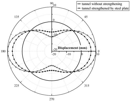
Figure 10.
Comparison of lining radial displacement between tunnels with and without steel plate strengthening.
Comparing the deformation patterns and the changes in the tunnel diameters of tunnels with and without strengthening, it is demonstrated that the deformation of the tunnel lining due to surcharge can be effectively minimized by using steel plate strengthening. The overall stiffness of tunnel lining was significantly improved after the strengthening.
4.3. Moment and Axial Force
In order to better understand the change of lining forces due to the steel plate strengthening, the moment and axial force within the concrete lining or the steel plate are extracted for comparison. As shown in Figure 11, the lining moment of tunnels with and without steel plate strengthening are compared. The moment value is treated as positive when tensile stress appears at the outer edge and compression stress appears at the inner edge of the concrete tunnel lining. The lining moment of the tunnel without strengthening is 451.6 kNm at the tunnel crown and −444.3 kNm at the tunnel spring lining. The peak lining moment of the strengthened tunnel is 303.1 kNm at the tunnel crown and −297.9 kNm at the tunnel spring line. The lining moment has been minimized by 32.9% due to the steel plate strengthening.
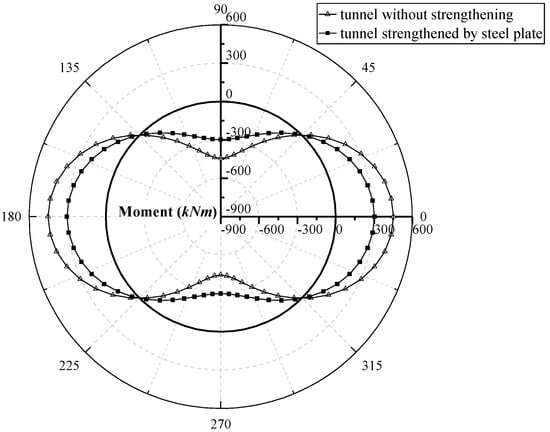
Figure 11.
Comparison of moment in the concrete lining of tunnels with and without steel plate strengthening.
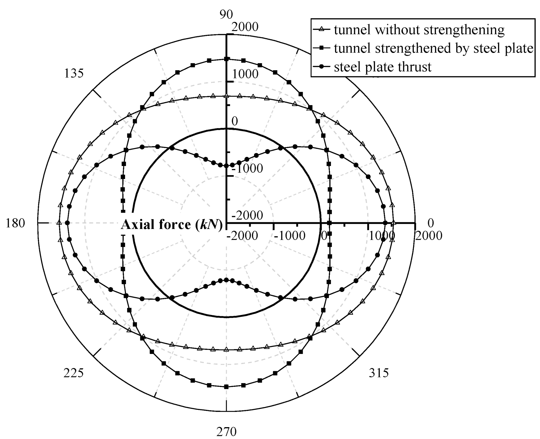
As shown in Figure 12, the axial force of tunnels with and without steel plate strengthening are illustrated. The compression thrust is treated as positive, while the tension thrust is negative. It is observed that the thrust in the concrete lining is minimized significantly due to the steel plate strengthening. As for the strengthened tunnel, the steel plate is subjected to tension at the tunnel crown and compression at the spring line.
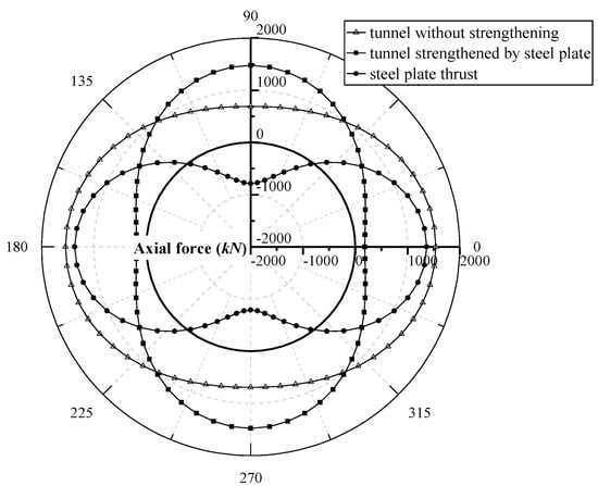
Figure 12.
Axial force in the lining of tunnels with and without steel plate strengthening.
4.4. Interface Stresses
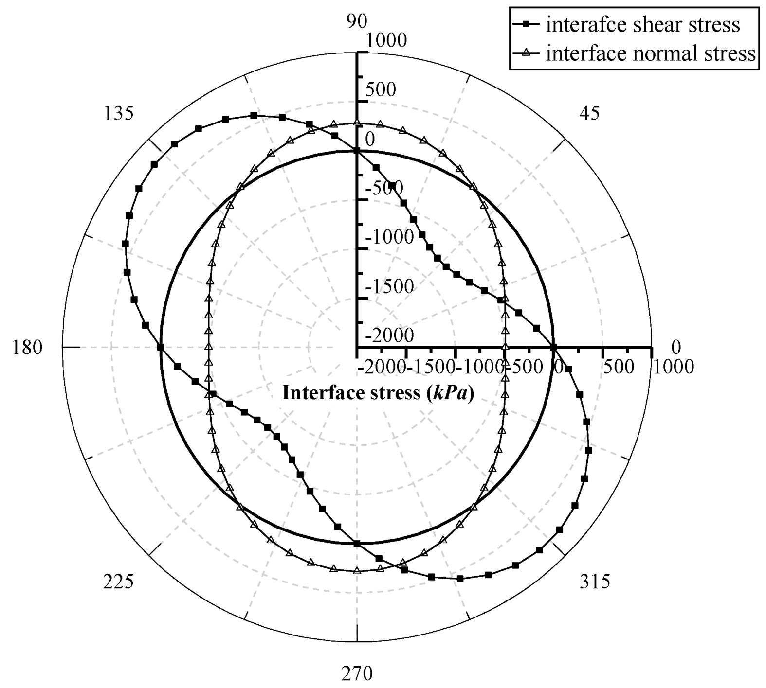
In order to better understand the interaction mechanism between the concrete lining and the steel plate, the interface stress distributions between two lining components have been extracted and shown in Figure 13. In the normal direction, tension is treated as positive, while in the tangential direction, the anticlockwise shear stress is treated as positive.
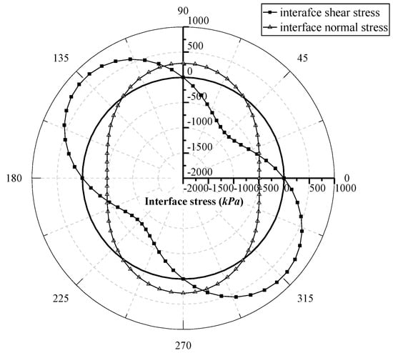
Figure 13.
Interface stress distributions of the tunnel with and without steel plate strengthening.
In terms of the interface normal stress, it is tension in the range of 51°~129° and 231°~309°, where the concrete lining and steel plate tend to separate. In the rest area of the interface, the interface stress is negative, where the concrete lining and the steel plate are compressed against each other. The maximum interface tension stress is 281.2 kPa at the tunnel crown and invert, while the maximum interface compression stress is −491.4 kPa at the tunnel spring lining.
In terms of the interface shear stress, the direction is clockwise in the range from 0°~90° and anticlockwise in the range form 90°~180°. The maximum interface shear stress is 781.5 kPa, which appears at the positions of θ = 45°, 135°, 225°, and 315°. Therefore, the interface shear strength at these positions must be guaranteed during the construction of the steel plate strengthening.
5. Discussion
Using the proposed analytical solution, the influence of two parameters, i.e., the interface property kcs and the steel plate thickness ts, are discussed in this section. This helps achieve a thorough understanding of the impact of these factors on the effectiveness of steel plate strengthening.
5.1. Influence of Interface Shear Stiffness
In this paper, the concrete-steel interface property of a strengthened tunnel is indicated by introducing an interface shear stiffness coefficient, i.e., kcs. The value of kcs was evaluated according to a shearing test on the concrete-steel bonded joint. The value of kcs could vary from case to case, influenced by concrete lining properties, epoxy resin types, shearing test methods, etc. More experimental research is needed to study the interface shear stiffness coefficient, which is beyond the scope of this paper. Here, the influence of the concrete-steel interface shear stiffness on the steel plate strengthened tunnel lining performance is discussed in terms of the interface stress and tunnel lining force.
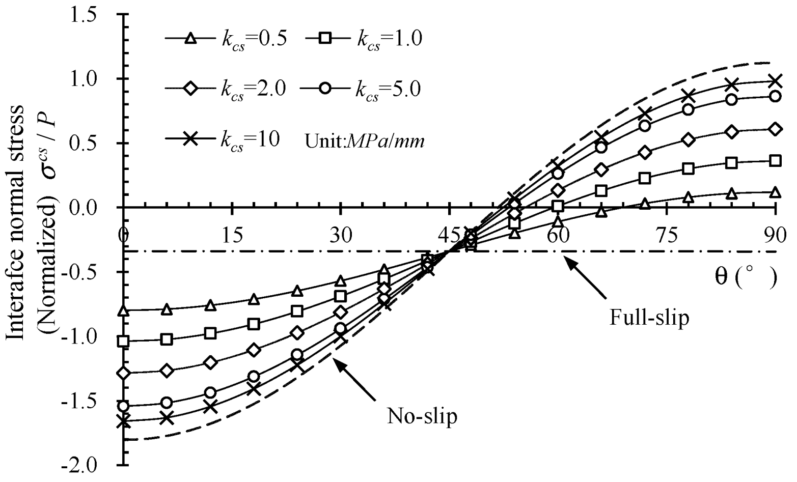
The influence of the interface shear stiffness on the normal and shear stress between the concrete lining and the steel plate are shown in Figure 14 and Figure 15, respectively. Normalized interface stresses in both normal and tangential directions, namely and , are extracted along the tunnel-steel interface from θ = 0° to 90°. It is observed that values of the interface shear and normal stress increased significantly, as kcs increased from 0.2 to 10 MPa/mm. In terms of the no-slip mode, the maximum compressive stress with normalized value of −1.82 and the maximum tensile stress with a normalized value of 1.17 is observed at the positions of the tunnel spring-line and crown, respectively. The maximum shear stress with a normalized value of −3.05 is observed at the position θ = 45°, while the shear stresses vanish at positions of the tunnel spring-line and crown. In terms of the full-slip mode, constant stress with a normalized value of −0.33 in the normal direction and zero in the tangential direction are observed along the interface. This indicates that in the full slip condition, no shear resistance exits at the tunnel-steel interface. The steel plate could only provide a very small effect against the uniform constriction deformation.
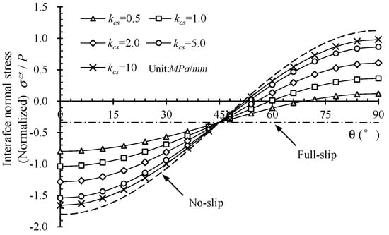
Figure 14.
Influence of kcs on the interface normal stress.
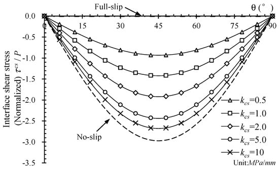
Figure 15.
Influence of kcs on the interface shear stress.
In addition, as the value of kcs increased, the patterns of the interface stress distribution were evaluated in the case of full-slip conditions towards that of the no-slip interface condition. The interface normal stress close to the tunnel crown changed from compression to tension, while the compression stress close to the tunnel spring lining kept increasing. When the value of kcs is relatively large, it indicates that the situation that the adhesive works well and the steel plate is perfectly bonded to the concrete tunnel lining. The effectiveness of steel plate strengthening is at its best performance, and the two components behave in terms of a composite lining system. When the value of kcs decreases to a relatively small value, it indicates that the bonding adhesive gradually loses function, and the tunnel lining and the steel plate work separately with only small compressive interaction between the two components.
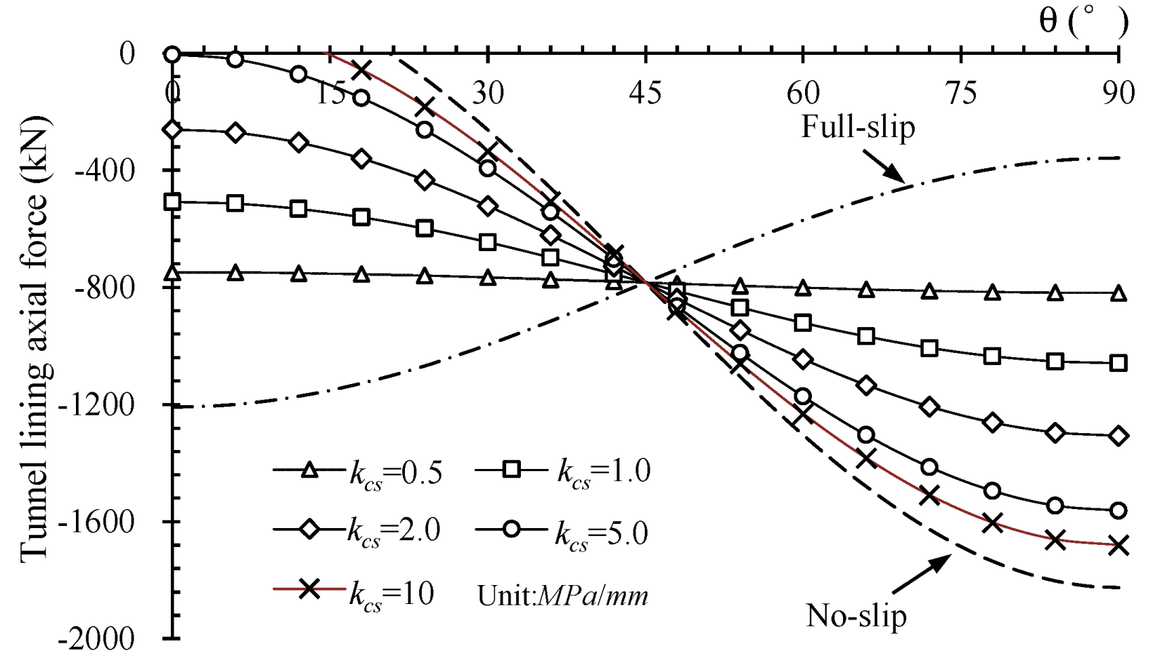
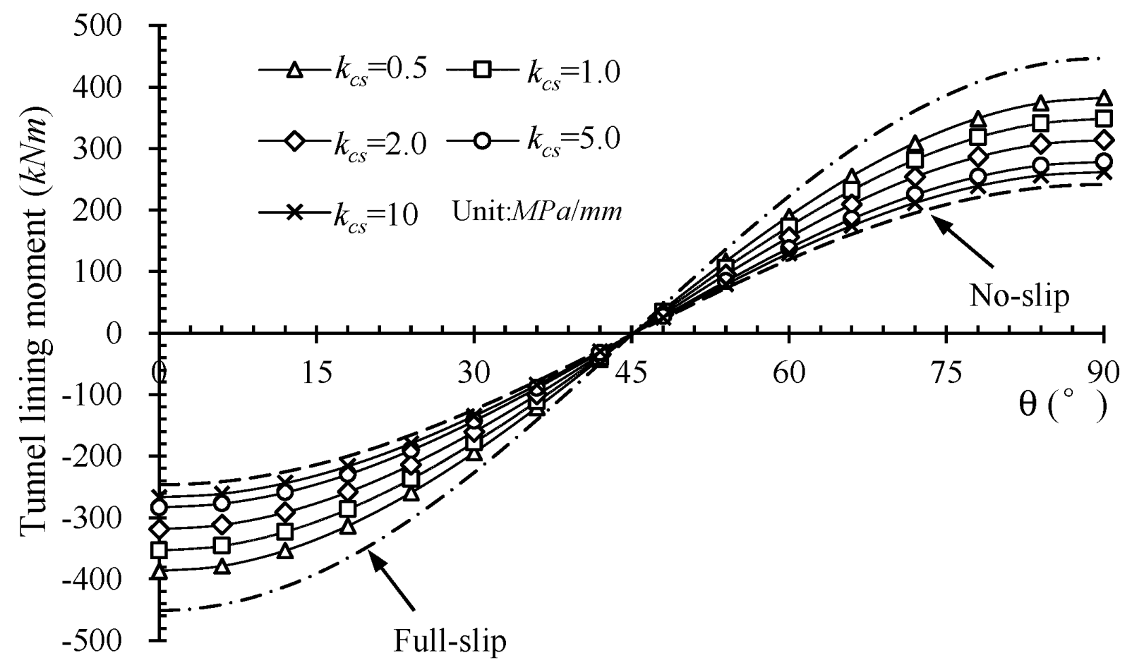
In order to investigate the influence of interface shear stiffness on the composite behaviour of steel plate strengthened tunnel linings. The axial force and moment of strengthened tunnel lining with different values of the interface stiffness coefficient kcs are extracted as shown in Figure 16 and Figure 17. In these figures, the positive and negative axial force indicates tension and compression section force, respectively. The positive section moment indicates that the intrados of tunnel lining is subjected to tensile strain, while the negative section moment indicates that the intrados of tunnel lining is subjected to compressive strain. It is observed that the interface shear stiffness significantly influences the value of both force and moment in the tunnel lining. In terms of the no-slip mode, the maximum axial force appears at the position of the tunnel crown, where the positive section moment reaches its peak value. In terms of the full-slip mode, the maximum axial force appears at the position of the tunnel spring-line, where the negative section moment reaches its peak value. As kcs increases from 0.5 to 10 MPa/mm, the absolute value of the axial force decreases within the range of 0 to 45°, while the axial force increases within the range of 45° to 90°. The value of the moment decreases as the value of kcs improves. The peak moment and axial force are at positions of the tunnel crown and invert.
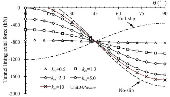
Figure 16.
Influence of kcs on tunnel lining axial force.

Figure 17.
Influence of kcs on tunnel lining moment.
From above analysis, it can be seen that the improvement of the interface shear stiffness can significantly enhance the overall structural stiffness of the strengthened tunnel lining, which results in increases in the interaction stresses and lining forces simultaneously. It also implies that a stiffer interface connection also calls for a higher strength of the interface bonding property. Comparing the situations of no-slip, full-slip, and interface with different values of kcs, the no-slip, and full-slip modes represent steel strengthened tunnel with the ideal interface bonding scenarios. The no-slip interface indicates the condition that the steel plate is perfectly bonded to the concrete tunnel lining, while the full-slip interface indicates the condition that no resistance exists between the steel plate and tunnel linings. It is noticed that the full-slip and no-slip modes are the lower and upper bond of the elastic slip model with interface coefficient kcs adopted as 0 and infinite, respectively. The strengthened tunnel with a relatively large value of the interface coefficient kcs represents a situation in which the adhesive could provide good bonding effectiveness. As the interface coefficient kcs decreases to a relatively small value, it indicates that the bonding performance of the adhesive layer gradually degrades, and the steel plate would contribute very little effectiveness in improving the structural performance of the tunnel linings.
5.2. Influence of Steel Plate Thickness
The thickness of the steel plate is one of the most important design parameters that determine the cost and effectiveness of the tunnel strengthening projects. The purpose of this section is to provide an integrated understanding of the influence of the steel plate thickness, which is hoped to contribute to a better application of this tunnel strengthening method. The influence of steel plate thickness on the strengthened tunnel lining performance is analyzed under different conditions of soil elastic modulus using the proposed analytical solutions. The results are shown in Figure 18.
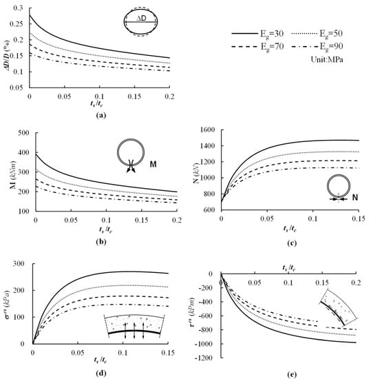
Figure 18.
Influence of the steel plate thickness on performance of the strengthened tunnel, (a) deformation, (b) moment at tunnel invert, (c) axial force at tunnel invert, (d) interface tension stress at tunnel crown, (e) peak interface shear stress.
It can be observed from Figure 18a that the tunnel deformation declines nonlinearly with an increase in the steel plate thickness; the deformation becomes more insensitive as the steel plate becomes thicker. When the value of ts/tc is less than 0.06, the tunnel deformation could be significantly reduced by making the steel plate thicker. However, when the value of ts/tc goes higher than 0.1, the effect of increasing steel plate thickness becomes less evident.
Similarly, the influence of the steel plate thickness on the lining moment and axial force at the tunnel invert is illustrated in Figure 18b,c, respectively. It can be observed that as the steel plate thickness increases, the axial force increases while the moment decreases. When ts/tc is smaller than 0.05, the internal force within the tunnel lining is sensitive to the change in steel thickness. A small increase in steel thickness causes a significant change in the axial force and moment. However, they are both less sensitive to an increase in the steel thickness as ts/tc goes higher than 0.1.
Subsequently, the influence of steel thickness on the interaction stresses at the interface between the tunnel lining and the steel plate is analyzed. According to the distribution patterns of the interface stress in the normal and tangential directions, as shown in Figure 9, the maximum detaching stress appears at the tunnel crown and invert, while the peak shearing stress appears at the positions near the tunnel shoulders. Therefore, the influence of the steel thickness on the values of the interaction stress at these two positions is illustrated in Figure 18d,e.
It can be seen that the maximum tension and shearing stresses increased nonlinearly as the steel thickness increased. When the steel plate is relatively thin, the interaction stress is small, but a small increase in the steel thickness leads to a rapid increase in tension and shearing stresses at the interface. As the steel plate thickens, this trend becomes less significant. This is because as the inner steel plate becomes stronger, it can carry more load from the lining system. Consequently, greater interaction forces are needed at the interface to guarantee the compatibility of the two lining components.
In addition, from the curves for different soil elastic modulus, it is evident that as the ground soil stiffens, the tunnel deformation and the internal and interaction stresses become smaller. This demonstrates that stiffer soil will benefit the performance of the steel plate strengthened tunnel lining.
From all the discussion above, it can be demonstrated that an increase in steel plate thickness can significantly control the tunnel lining deformation, especially when the steel thickness itself is thin. Meanwhile, the interaction stress at the interface will increase simultaneously, which demands a higher bonding strength. The peak tension and shear stresses are critical to the safety of the strengthened tunnel lining, which should be carefully considered during the design and construction process.
6. Conclusions
This article presents simplified analytical solutions of a circular tunnel strengthened by a steel plate with consideration of various interface slip modes. Using the proposed solutions, the performance of tunnels with and without strengthening is analyzed, and the influence of some essential factors on the strengthened tunnel lining performance is discussed. Some conclusions are summarized:
- The simplified analytical solutions proposed in this article provide a concise way of analyzing a circular tunnel strengthened by steel plates, which can consider the bonding properties of the concrete-steel interface.
- The structure stiffness of tunnel lining can be significantly improved by using steel plate strengthening. According to the case analyzed in this paper, comparing the tunnels with and without strengthening, deformation of the tunnel strengthened by steel plate has been minimized by 32.2%.
- The improvement of the interface shear stiffness can enhance the overall structural stiffness of the strengthened tunnel lining, which results in increases in the interaction stresses and lining forces simultaneously.
- Greater achievement in both strengthening effectiveness and cost efficiency can be obtained by controlling a ratio of the steel thickness to the tunnel lining thickness less than 0.1.
Author Contributions
Conceptualization, W.Z., D.Z. and H.H.; methodology, W.Z.; software, W.Z.; validation, W.Z.; formal analysis, W.Z.; investigation, W.Z.; resources, W.Z.; data curation, W.Z.; writing—original draft preparation, W.Z.; writing—review and editing, W.Z., D.C., D.Z., H.H. and K.S.; visualization, W.Z.; supervision, D.C., D.Z. and H.H.; project administration, D.C., D.Z., H.H. and K.S.; funding acquisition, D.Z., H.H. and K.S. All authors have read and agreed to the published version of the manuscript.
Funding
This research was funded by the National Science Foundation Committee grant number 52130805, the Key Laboratory of Transportation Tunnel Engineering grant number TTE2017-09 and Department of Transport of Yunnan Province grant number 201825.
Institutional Review Board Statement
Not applicable.
Informed Consent Statement
Not applicable.
Acknowledgments
In addition, this work is mainly conducted by the first author while studying in the University of Birmingham as a visiting research student supported by the Chinese Government Scholarship, both the China Scholarship Council and the University of Birmingham are much appreciated.
Conflicts of Interest
The authors declare no conflict of interest.
References
- Chang, C.T.; Sun, C.W.; Duann, S.W.; Hwang, R.N. Response of a Taipei Rapid Transit System (TRTS) tunnel to adjacent excavation. Tunn. Undergr. Space Technol. 2001, 16, 151–158. [Google Scholar] [CrossRef]
- Huang, H.; Shao, H.; Zhang, D.; Wang, F. Deformational responses of operated shield tunnel to extreme surcharge: A case study. Struct. Infrastruct. Eng. 2017, 13, 345–360. [Google Scholar] [CrossRef]
- Van Empel, W.H.; Sip, J.W.; Haring, F.P. Design of repair measures of a damaged shield driven tunnel. Tunn. Undergr. Space Technol. 2006, 21, 338–339. [Google Scholar] [CrossRef]
- RAIB. Rail Accident Report: Penetration and Obstruction of a Tunnel between Old Street and Essex Road Stations, London 8 March 2013; Rail Accident Investigation Branch, Department for Transport: Derby, UK, 2014.
- Wang, F.; Zhou, M.; Zhang, D.; Huang, H.; Chapman, D. Random evolution of multiple cracks and associated mechanical behaviors of segmental tunnel linings using a multiscale modeling method. Tunn. Undergr. Space Technol. 2019, 90, 220–230. [Google Scholar] [CrossRef]
- Wang, F.; Huang, H.; Zhang, D.; Zhou, M. Cracking feature and mechanical behavior of shield tunnel lining simulated by a phase-field modeling method based on spectral decomposition. Tunn. Undergr. Space Technol. 2022, 119, 104246. [Google Scholar] [CrossRef]
- Zhai, W.; Chapman, D.; Zhang, D.; Huang, H. Experimental study on the effectiveness of strengthening over-deformed segmental tunnel lining by steel plates. Tunn. Undergr. Space Technol. 2020, 104, 103530. [Google Scholar] [CrossRef]
- Kiriyama, K.; Kakizaki, M.; Takabayashi, T.; Hirosawa, N.; Takeuchi, T.; Hajohta, H.; Yano, Y.; Imafuku, K. Structure and construction examples of tunnel reinforcement method using thin steel panels. Nippon. Steel Tech. Rep. 2005, 92, 45–50. [Google Scholar]
- Zhao, H.; Liu, X.; Bao, Y.; Yuan, Y.; Bai, Y. Simplified nonlinear simulation of shield tunnel lining reinforced by epoxy bonded steel plates. Tunn. Undergr. Space Technol. 2016, 51, 362–371. [Google Scholar] [CrossRef]
- Zhang, D.M.; Zhai, W.Z.; Huang, H.W.; Chapman, D. Robust retrofitting design for rehabilitation of segmental tunnel linings: Using the example of steel plates. Tunn. Undergr. Space Technol. 2019, 83, 231–242. [Google Scholar] [CrossRef] [Green Version]
- Golpasand, M.R.B.; Do, N.A.; Dias, D. Impact of pre-existent Qanats on ground settlements due to mechanized tunneling. Transp. Geotech. 2019, 21, 100262. [Google Scholar] [CrossRef]
- Liu, M.B.; Liao, S.M.; Xu, J.; Men, Y.Q. Analytical solutions and in-situ measurements on the internal forces of segmental lining produced in the assembling process. Transp. Geotech. 2021, 27, 100478. [Google Scholar] [CrossRef]
- Wood, A.M. The circular tunnel in elastic ground. Geotechnique 1975, 25, 115–127. [Google Scholar] [CrossRef]
- Morgan, H.D. A contribution to the analysis of stress in a circular tunnel. Geotechnique 1961, 11, 37–46. [Google Scholar] [CrossRef]
- Einstein, H.H.; Schwartz, C.W. Simplified analysis for tunnel supports. J. Geotech. Eng. Div. 1979, 105, 499–518. [Google Scholar] [CrossRef]
- Bobet, A. Analytical solutions for shallow tunnels in saturated ground. J. Eng. Mech. 2001, 127, 1258–1266. [Google Scholar] [CrossRef]
- Zhang, D.; Huang, H.; Phoon, K.K.; Hu, Q. A modified solution of radial subgrade modulus for a circular tunnel in elastic ground. Soils Found. 2014, 54, 225–232. [Google Scholar] [CrossRef] [Green Version]
- González, C.; Sagaseta, C. Patterns of soil deformations around tunnels. Application to the extension of Madrid Metro. Comput. Geotech. 2001, 28, 445–468. [Google Scholar] [CrossRef]
- Park, K.H. Elastic solution for tunneling-induced ground movements in clays. Int. J. Géoméch. 2004, 4, 310–318. [Google Scholar] [CrossRef]
- Pinto, F.; Whittle, A.J. Ground Movements due to Shallow Tunnels in Soft Ground. I: Analytical Solutions. J. Geotech. Geoenviron. Eng. 2014, 140, 04013040. [Google Scholar] [CrossRef] [Green Version]
- Pinto, F.; Zymnis, D.M.; Whittle, A.J. Ground Movements due to Shallow Tunnels in Soft Ground. II: Analytical Interpretation and Prediction. J. Geotech. Geoenviron. Eng. 2014, 140, 04013041. [Google Scholar] [CrossRef] [Green Version]
- Mason, D.P.; Abelman, H. Support provided to rock excavations by a system of two liners. Int. J. Rock Mech. Min. Sci. 2009, 46, 1197–1205. [Google Scholar] [CrossRef]
- El Naggar, H.; Hinchberger, S.D.; Lo, K.Y. A closed-form solution for composite tunnel linings in a homogeneous infinite isotropic elastic medium. Can. Geotech. J. 2008, 45, 266–287. [Google Scholar] [CrossRef] [Green Version]
- El Naggar, H.; Hinchberger, S.D. An analytical solution for jointed tunnel linings in elastic soil or rock. Can. Geotech. J. 2008, 45, 1572–1593. [Google Scholar] [CrossRef]
- Zhai, W.; Chapman, D.; Faramarzi, A.; Huang, H.; Zhang, D. Multi-objective optimisation design for composite tunnel linings using non-dominated sorting genetic algorithm. In Geotechnical Aspects of Underground Construction in Soft Ground; CRC Press: Boca Raton, FL, USA, 2021. [Google Scholar]
- Timoshenko, S.P.; Goodier, J.N.; Abramson, H.N. Theory of Elasticity, 3rd ed.; McGraw-Hill: New York, NY, USA, 1970. [Google Scholar]
- Täljsten, B. Defining anchor lengths of steel and CFRP plates bonded to concrete. Int. J. Adhes. Adhes. 1997, 17, 319–327. [Google Scholar] [CrossRef]
- Oh, B.H.; Cho, J.Y.; Park, D.G. Failure behavior and separation criterion for strengthened concrete members with steel plates. J. Struct. Eng. 2003, 129, 1191–1198. [Google Scholar] [CrossRef]
- Jurkiewiez, B.; Tout, F.; Ferrier, E. Push-out and bending tests of steel-concrete adhesively bonded composite elements. Eng. Struct. 2021, 231, 111717. [Google Scholar] [CrossRef]


Publisher’s Note: MDPI stays neutral with regard to jurisdictional claims in published maps and institutional affiliations. |
© 2022 by the authors. Licensee MDPI, Basel, Switzerland. This article is an open access article distributed under the terms and conditions of the Creative Commons Attribution (CC BY) license (https://creativecommons.org/licenses/by/4.0/).