
Natural FRCM and Heritage Buildings: Experimental Approach to Innovative Interventions on “Wall Beams”


Abstract
:1. Introduction
2. Innovative Experimental Campaign
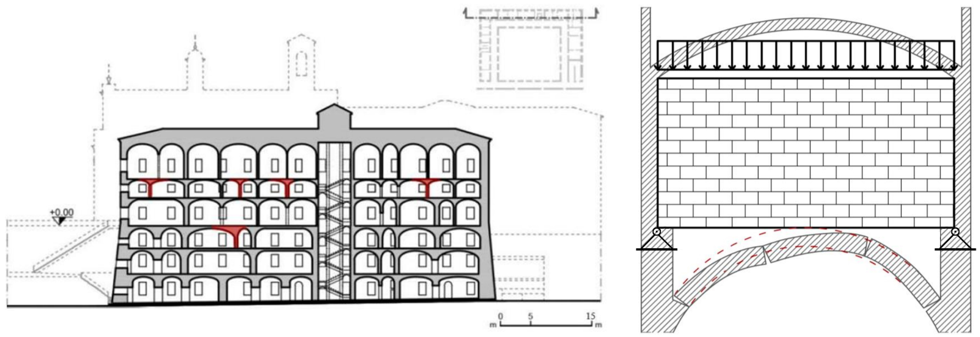
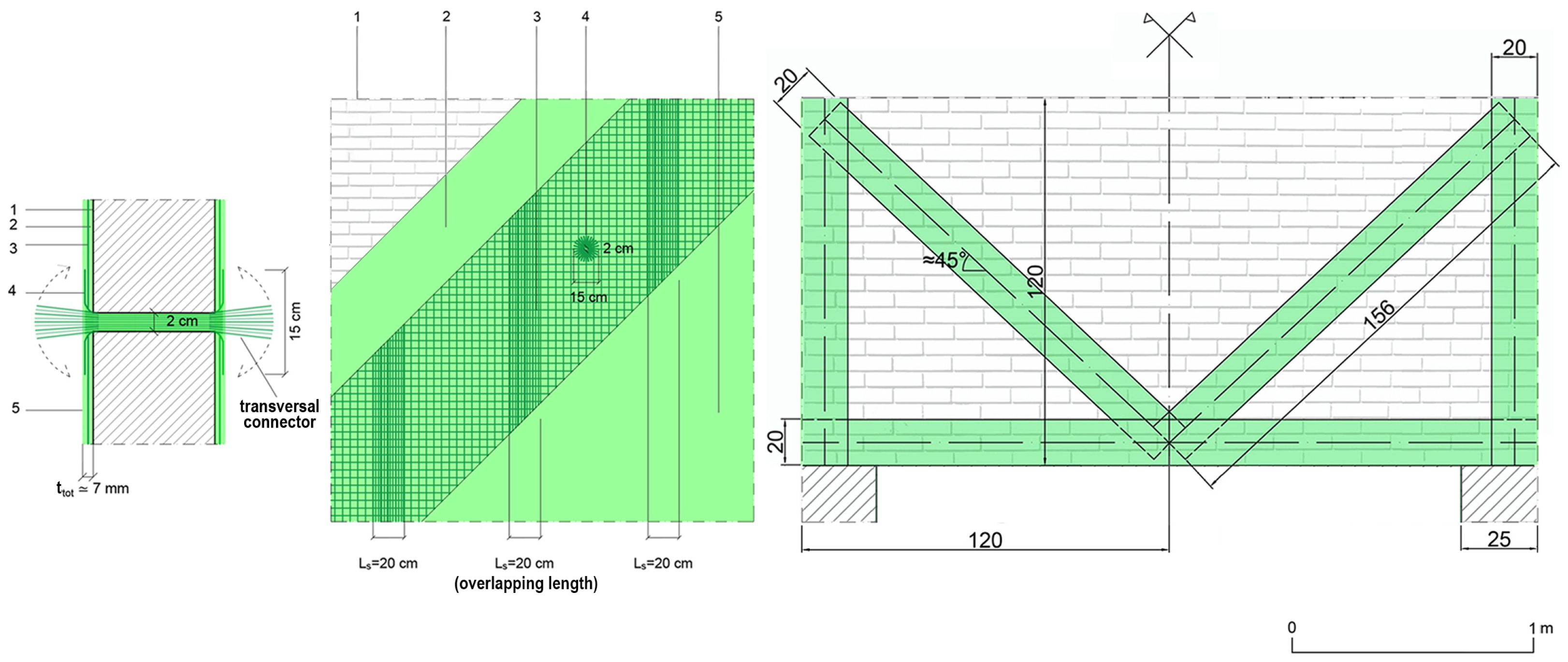
2.1. Non-Canonical Application Criteria for FRCM on Wall Beams
- good mechanical properties in the face of low thickness and little weight;
- easy installation modalities ensuring the continuation of the buildings’ activities;
- use of inorganic mortar (less aggressive than epoxy resins) that permits better transpiration to masonry;
- chance to recycle, considering the opportunity to use natural origin nets and matrices.
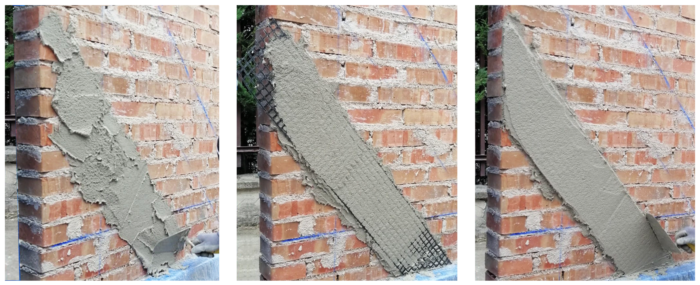
- the cleaning of the surface of the masonry substrate and its saturation and wetting (condition s.s.a., in technical jargon);
- application of a first layer of lime inorganic mortar made by a fine grain, with a maximum diameter of the aggregate equal to 1.2 mm;
- positioning of the basaltic fibers that are a bi-directional net with 20 mm square mesh;
- application of a second layer of mortar with the same features as the previous one.
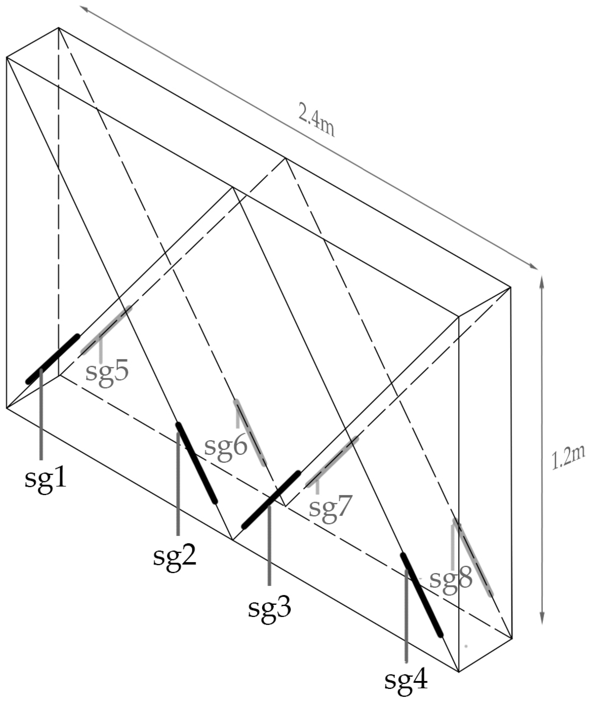
2.2. Experimental Setup and Prototypes’ Mechanical Properties
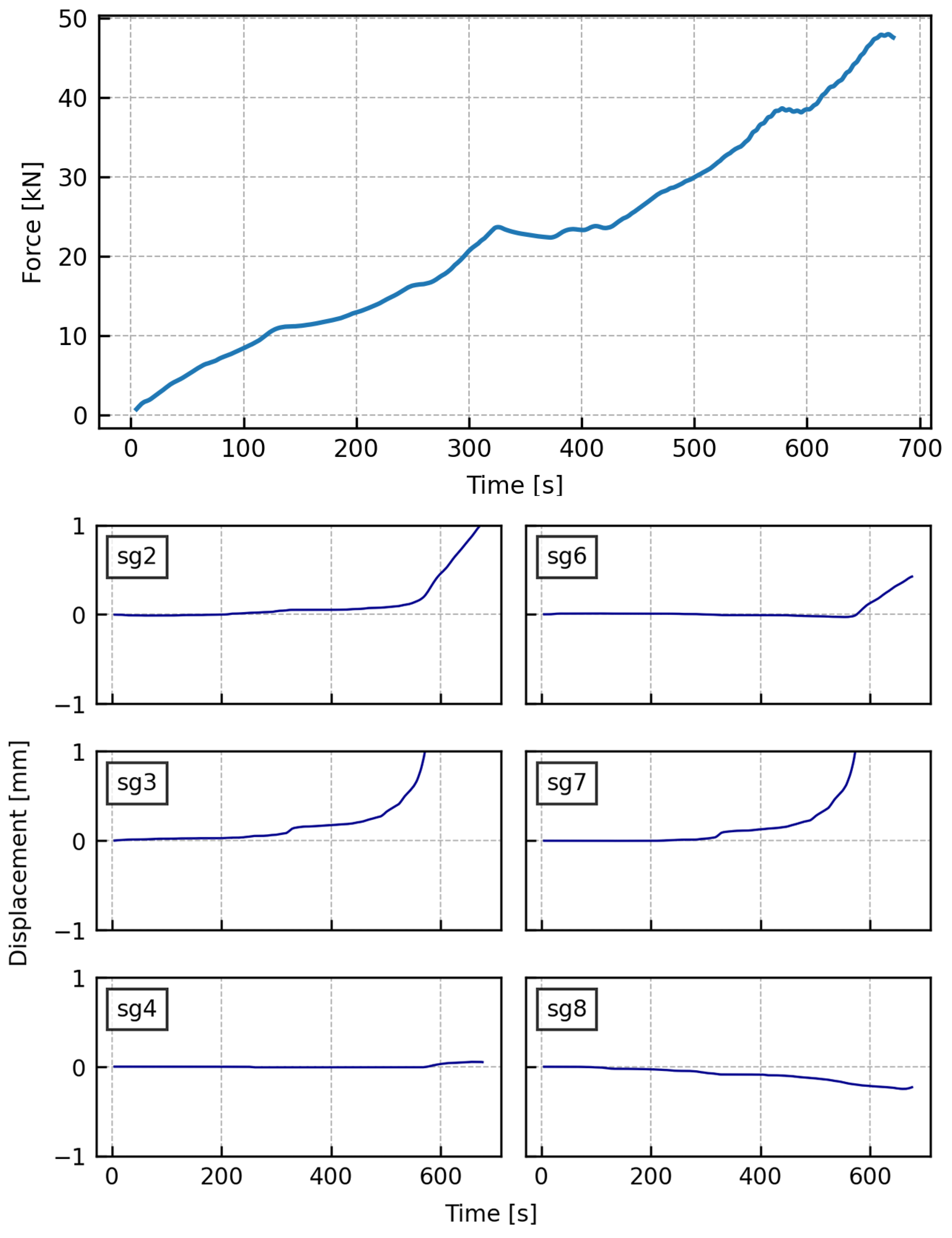
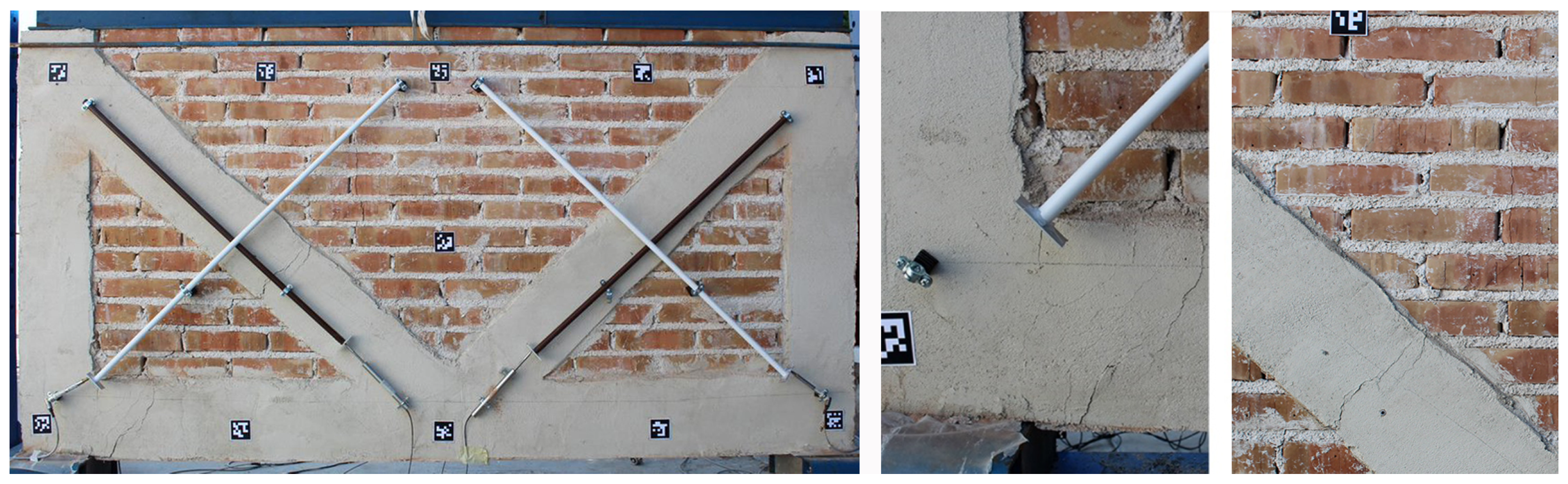
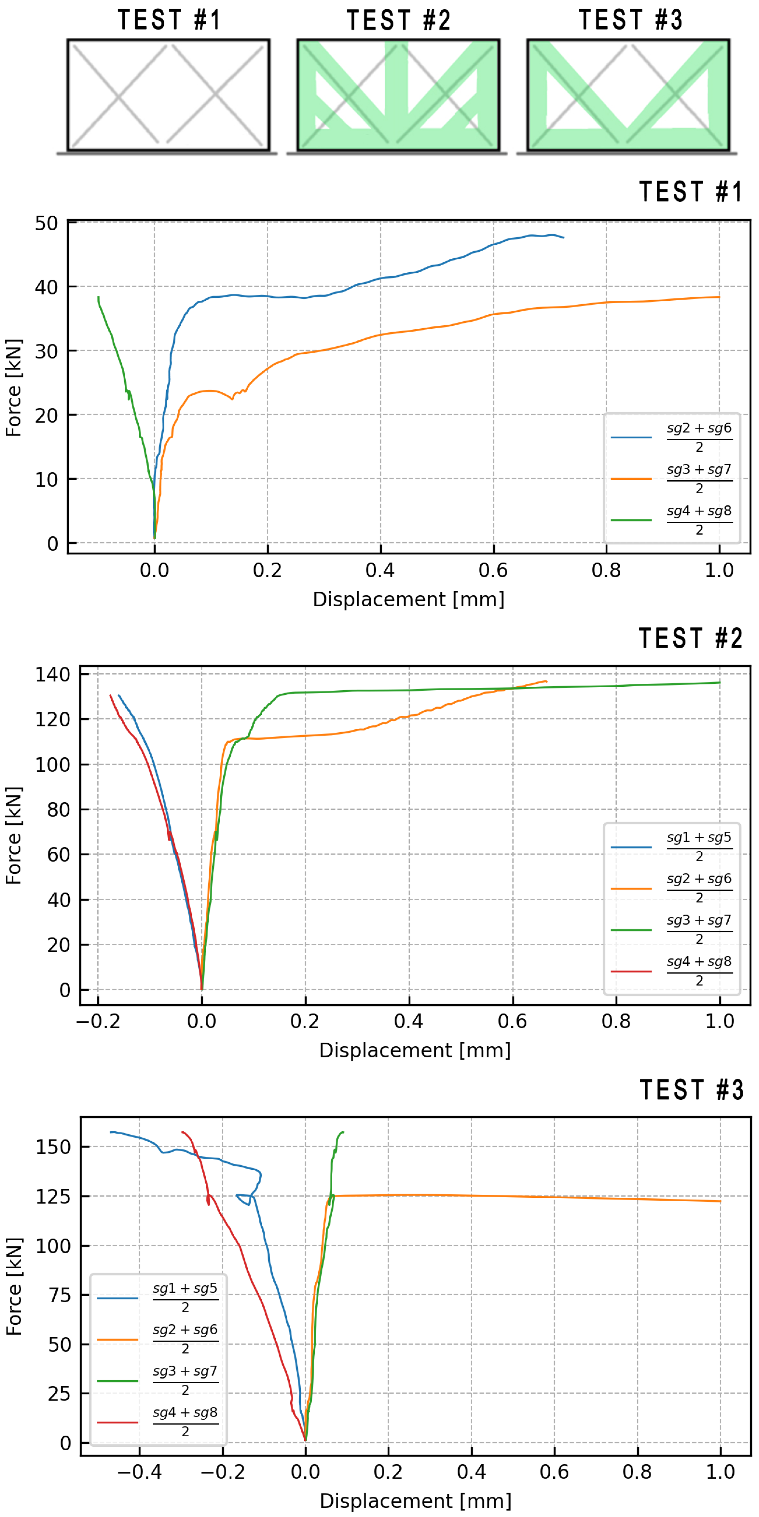
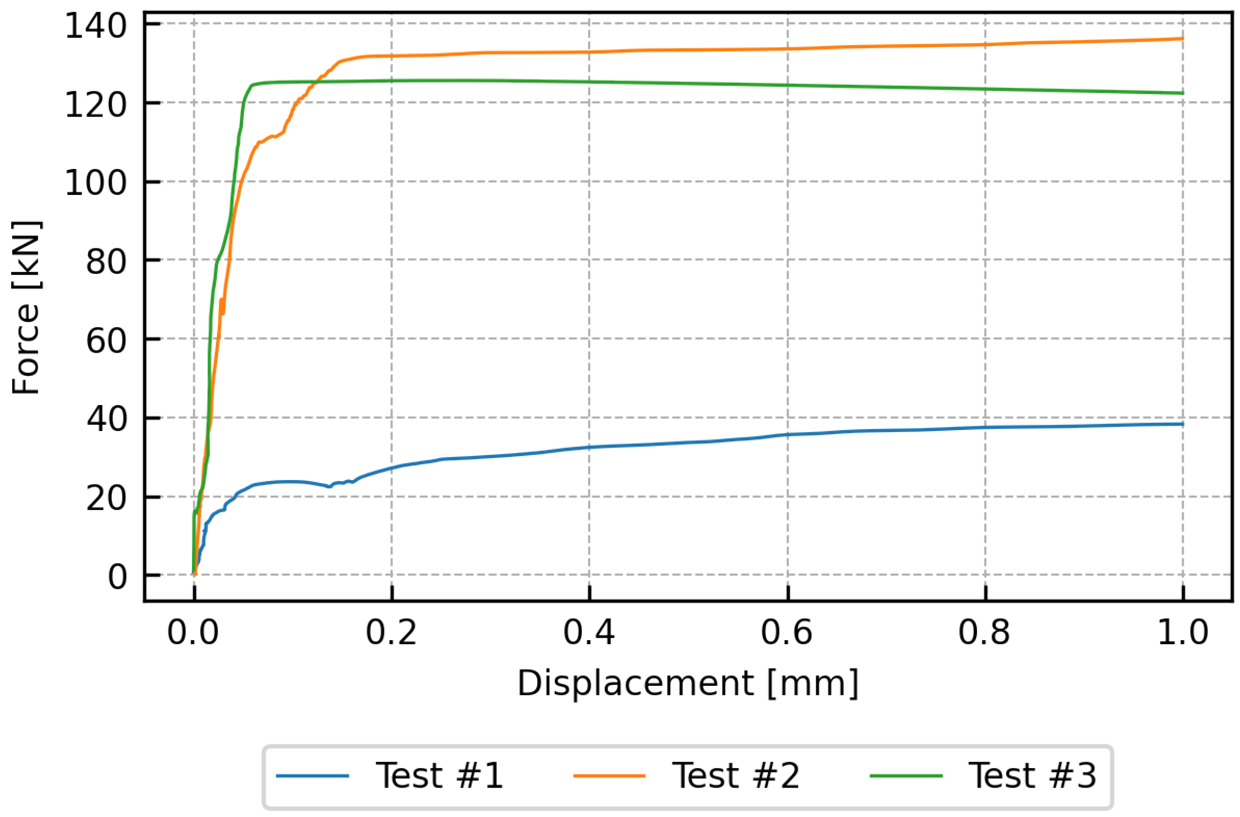
3. Experimental Results
- Test #1
- Experimental test on the unreinforce wall
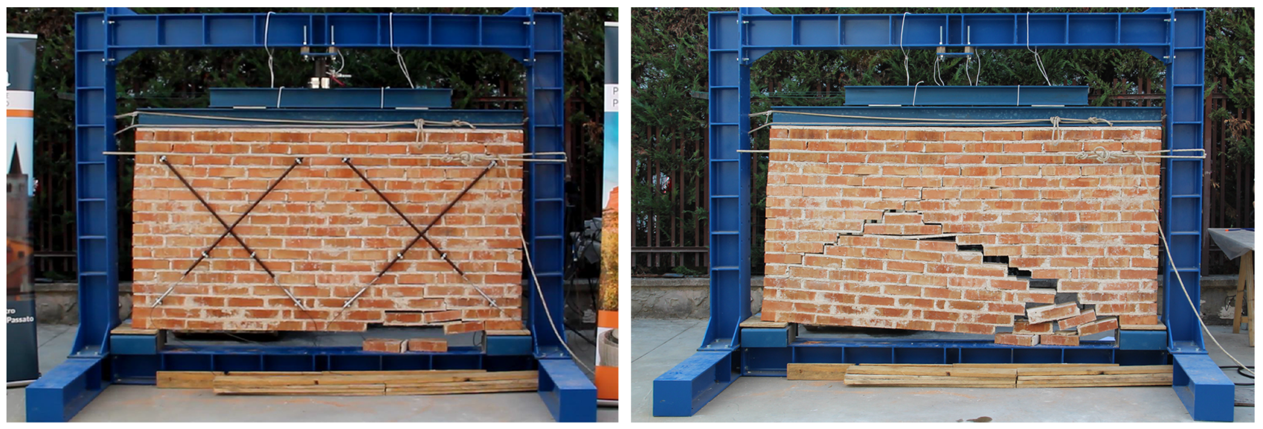
- Test #2
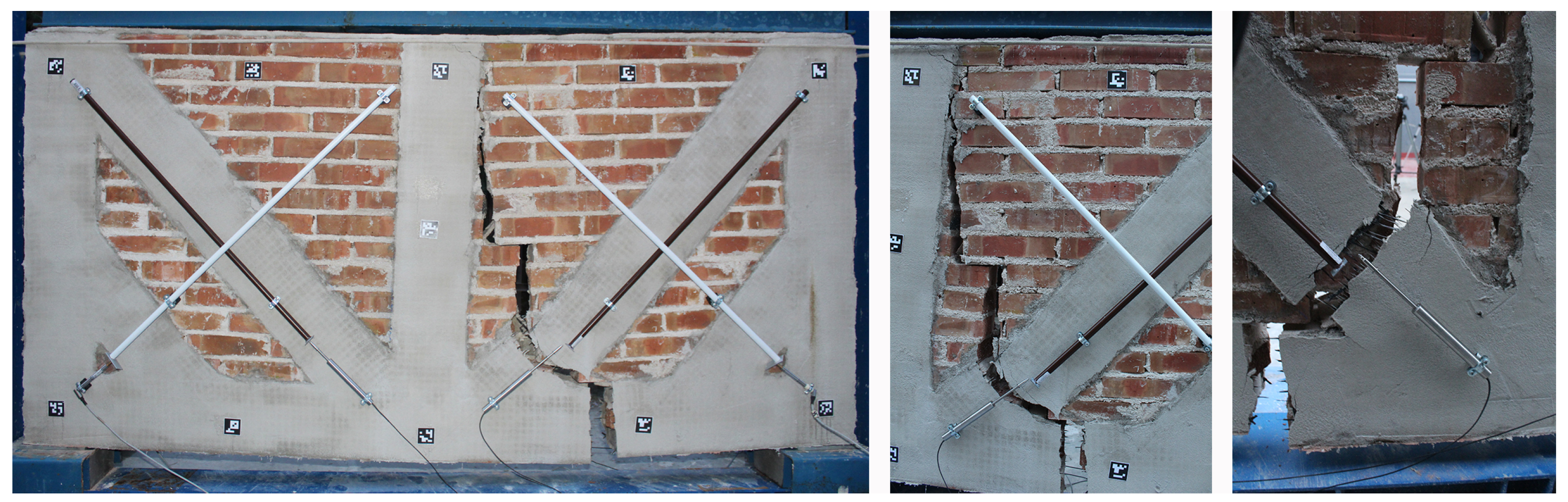
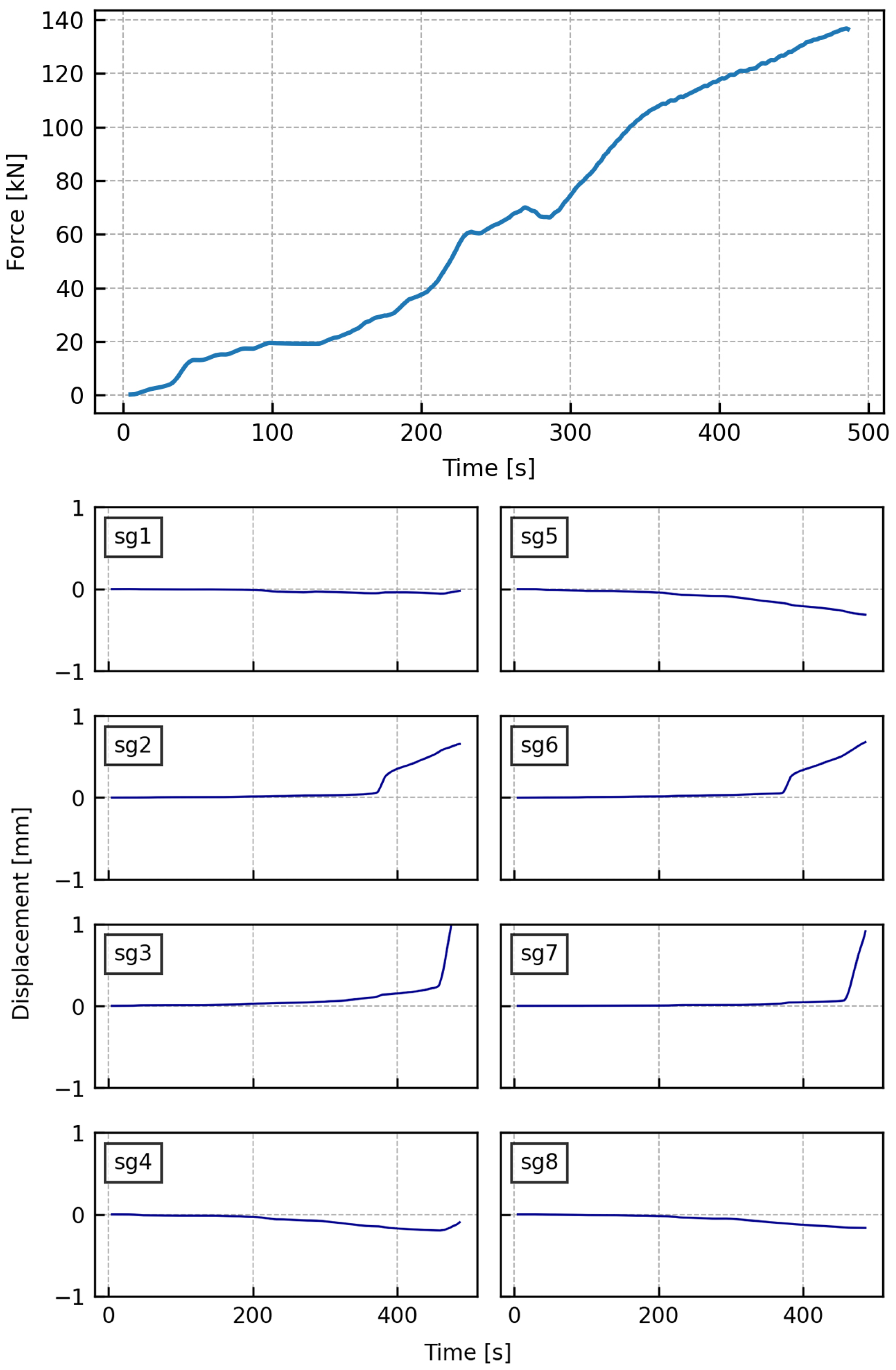
- Experimental test on the reinforced wall
- Test #3
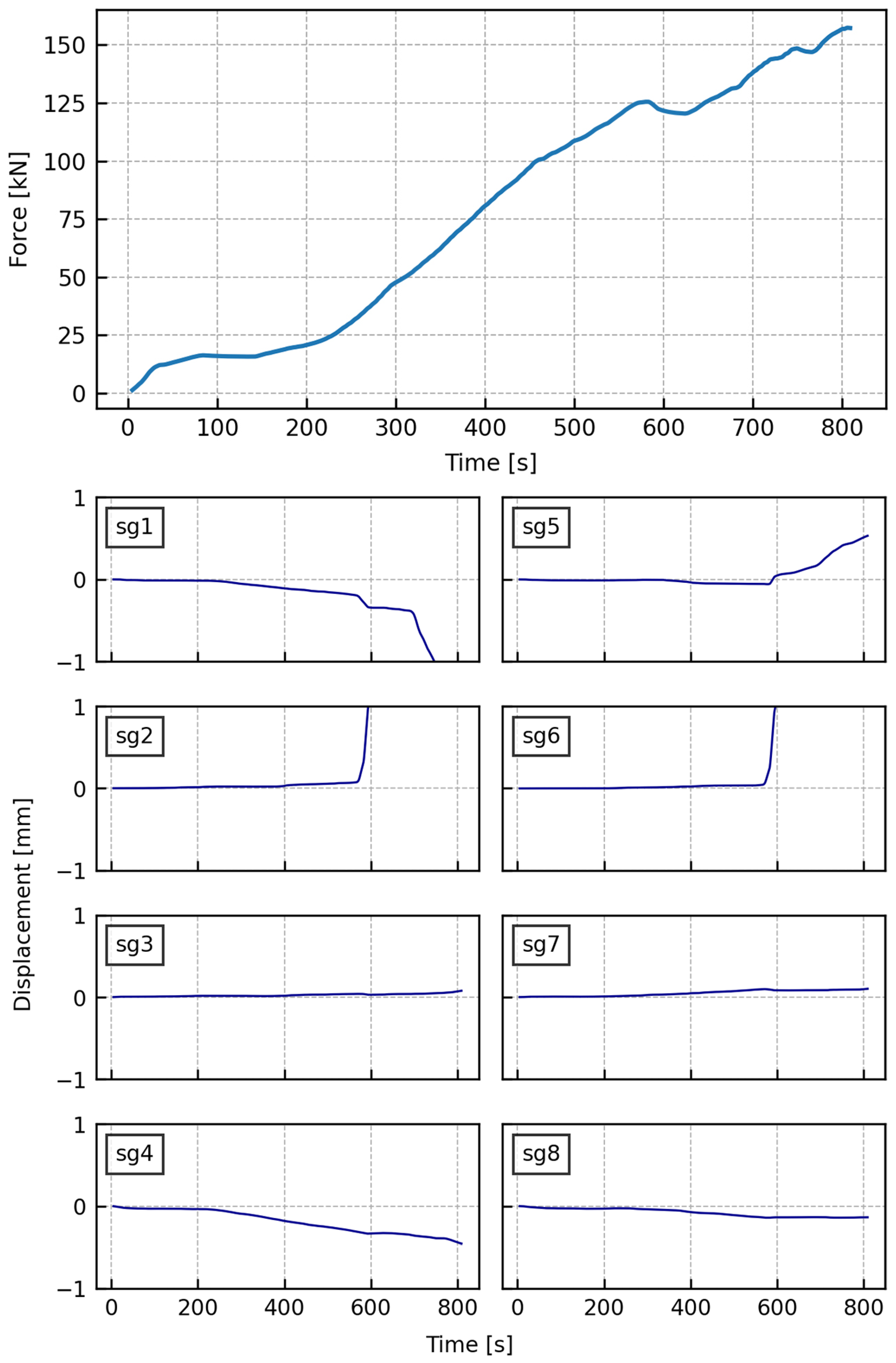
- Experimental test on the reinforced wall with “Green Tape”
4. Critical Analysis of Outcomes
5. Conclusions
Author Contributions
Funding
Institutional Review Board Statement
Informed Consent Statement
Data Availability Statement
Acknowledgments
Conflicts of Interest
References
- Gusella, V.; Liberotti, R. Seismic Vulnerability of Sub-Structures: Vantitelli’s Modulus in Murena Palace. Buildings 2020, 10, 164. [Google Scholar] [CrossRef]
- Belardi, P.; Gusella, V.; Liberotti, R.; Sorignani, C. Built Environment’s Sustainability: The Design of the Gypso|TechA of the University of Perugia. Sustainability 2022, 14, 6857. [Google Scholar] [CrossRef]
- Barberà Giné, A.; Marín Ortega, S.; Isbert vaquer, X. Ús de solucions tampó gelificades per a la remoció de pintades vandàliques a la naveta des Tudons (Menorca). Unicum 2019, 18, 15–26. [Google Scholar]
- Marín Ortega, S.; Barberà Giné, A. Three different digitization techniques for works of art: RTI, photogrammetry, and laser scan arm. Advantages and drawbacks in the practical case of a Romanesque lipsanoteca. In Proceedings of the Arco 2020—1st International Conference on Art Collections 2020, Florence, Italy, 28–30 May 2020; Collotti, F.V., Verdiani, G., Brodini, A., Eds.; DIDAPRESS: Florence, Italy, 2021; Volume 18, pp. 125–139. [Google Scholar]
- Satta, M.L.; Ruggieri, N.; Tempesta, G.; Galassi, S. Remains of the ancient colonnade in the archaeological site of Pompeii, Italy: Vulnerability analysis and strengthening proposal. J. Cult. Herit. 2021, 52, 93–106. [Google Scholar] [CrossRef]
- Galassi, S.; Ruggieri, N.; Tempesta, G. A Novel Numerical Tool for Seismic Vulnerability Analysis of Ruins in Archaeological Sites. Int. J. Archit. Herit. 2020, 14, 1–22. [Google Scholar] [CrossRef]
- Liberotti, R.; Cluni, F.; Gusella, V. Vulnerability and seismic improvement of architectural heritage: The case of Palazzo Murena. Earthq. Struct. 2020, 18, 321–335. [Google Scholar] [CrossRef]
- Belardi, P.; Gusella, V.; Liberotti, R.; Sorignani, C. The Gipso|TECA of the University of Perugia: Conversion of a heritage building in a plaster cast gallery. In Proceedings of the Arco 2020—1st International Conference on Art Collections 2020, Florence, Italy, 28–30 May 2020; Collotti, F.V., Verdiani, G., Brodini, A., Eds.; DIDAPRESS: Florence, Italy, 2021; Volume 18, pp. 69–86. [Google Scholar]
- Cavalagli, N.; Gusella, V. Structural Investigation of 18th-Century Ogival Masonry Domes: From Carlo Fontana to Bernardo Vittone. Int. J. Archit. Herit. 2015, 9, 265–276. [Google Scholar] [CrossRef]
- CNR-DT 215/2018; Istruzioni per la Progettazione, l’Esecuzione ed il Controllo diInterventi di Consolidamento Statico Mediante l’utilizzo di Compositi Fibrorinforzati a Matrice Inorganica. Consiglio Nazionale per le Ricerche: Rome, Italy, 2018.
- RELUIS-WP 2; Compositi a Matrice Cementizia (FRCM)—Prove di Distacco di Sistemi di Rinforzi FRCM da Supporto in Muratura-Istruzioni per l’Esecuzione Delle Prove. Reluis: Naples, Italy, 2017.
- Circ. No 7 21/1/2019; Istruzioni per l’Applicazione Dell’“Aggiornamento Delle «Norme Tecniche per le Costruzioni»” di cui al D.M. 14/1/2018. Consiglio Superiore dei Lavori Pubblici: Rome, Italy, 2019.
- Alecci, V.; De Stefano, M.; Galassi, S.; Magos, R.; Stipo, G. Confinement of Masonry Columns with Natural Lime-Based Mortar Composite: An Experimental Investigation. Sustainability 2021, 13, 13742. [Google Scholar] [CrossRef]
- García-Macías, E.; Ubertini, F. Least Angle Regression for early-stage identification of earthquake-induced damage in a monumental masonry palace: Palazzo dei Consoli. Eng. Struct. 2022, 259, 114119. [Google Scholar] [CrossRef]
- Cavalagli, N.; Gusella, V.; Liberotti, R. Effect of Shape Uncertainties on the Collapse Condition of the Circular Masonry Arch. In Developments and Novel Approaches in Nonlinear Solid Body Mechanics; Abali, B.E., Giorgio, I., Eds.; Springer: Cham, Switzerland, 2020; pp. 455–467. [Google Scholar] [CrossRef]
- Palieraki, V.; Vintzileou, E.; Silva, J. Behavior of RC interfaces subjected to shear: State-of-the art review. Constr. Build. Mater. 2021, 306, 124855. [Google Scholar] [CrossRef]
- Vasiliki Palieraki, E.V.; Silva, J.F. Interface Shear Strength under Monotonic and Cyclic Loading. ACI Struct. J. 2022, 119, 17–28. [Google Scholar] [CrossRef]
- Dalalbashi, A.; De Santis, S.; Ghiassi, B.; Oliveira, D.V. Slip rate effects and cyclic behaviour of textile-to-matrix bond in textile reinforced mortar composites. Mater. Struct. 2021, 54, 108. [Google Scholar] [CrossRef]
- Abbass, A.; Paiva, M.C.; Oliveira, D.V.; Lourenço, P.B.; Fangueiro, R. Insight into the Effects of Solvent Treatment of Natural Fibers Prior to Structural Composite Casting: Chemical, Physical and Mechanical Evaluation. Fibers 2021, 9, 54. [Google Scholar] [CrossRef]
- Dalalbashi, A.; de Santis, S.; Ghiassi, B.; Oliveira, D.V. Cyclic Load Effects on the Bond Behavior of Textile Reinforced Mortar (TRM) Composites. Key Eng. Mater. 2022, 916, 74–81. [Google Scholar] [CrossRef]
- Wang, F.; Kyriakides, N.; Chrysostomou, C.; Eleftheriou, E.; Votsis, R.; Illampas, R. Experimental Research on Bond Behaviour of Fabric Reinforced Cementitious Matrix Composites for Retrofitting Masonry Walls. Int. J. Concr. Struct. Mater. 2021, 15, 22. [Google Scholar] [CrossRef]
- Illampas, R.; Ioannou, I.; Lourenço, P.B. Seismic appraisal of heritage ruins: The case study of the St. Mary of Carmel church in Cyprus. Eng. Struct. 2020, 224, 111209. [Google Scholar] [CrossRef]
- Giacco, G.; Mariniello, G.; Marrone, S.; Asprone, D.; Sansone, C. Toward a System for Post-Earthquake Safety Evaluation of Masonry Buildings. In Proceedings of the Image Analysis and Processing—ICIAP 2022, Lecce, Italy, 23–27 May 2022; Sclaroff, S., Distante, C., Leo, M., Farinella, G.M., Tombari, F., Eds.; Springer: Cham, Switzerland, 2022; pp. 312–323. [Google Scholar] [CrossRef]
- Ramirez, R.; Ghiassi, B.; Oliveira, D.V.; Lourenço, P.B. Preliminary Results on Natural Aging of GFRP-Reinforced Masonry Components Exposed to Outdoor Environmental Conditions. Key Eng. Mater. 2022, 916, 11–18. [Google Scholar] [CrossRef]
- Baraldi, D.; Boscato, G.; Cecchi, A.; de Carvalho Bello, C.B. An Updated Discrete Element Model for the In-Plane Behaviour of NFRCM Strengthened Masonry Walls. Key Eng. Mater. 2022, 916, 249–255. [Google Scholar] [CrossRef]
- Baldelli, J.; Baraldi, D.; Boscato, G.; Cecchi, A.; de Carvalho Bello, C.B.; Boscolo Zemelo, M.; Thatikonda, N.P. Numerical Analysis to Evaluate the Structural Performance of NFRCM (Natural Fabric-Reinforced Cementitious) Strengthened Masonry. Key Eng. Mater. 2022, 919, 49–54. [Google Scholar] [CrossRef]
- Di Re, P.; Addessi, D. Computational Enhancement of a Mixed 3D Beam Finite Element with Warping and Damage. J. Appl. Comput. Mech. 2022, 8, 260–281. [Google Scholar] [CrossRef]
- Addessi, D.; Di Re, P.; Cimarello, G. Enriched beam finite element models with torsion and shear warping for the analysis of thin-walled structures. Thin-Walled Struct. 2021, 159, 107259. [Google Scholar] [CrossRef]
- Vermeltfoort, A.; Martens, D. Composite action in masonry walls under vertical in-plane loading: Experimental results compared with predictions. Can. J. Civ. Eng. 2015, 42, 449–462. [Google Scholar] [CrossRef]
- Tzamtzis, A.; Asteris, P. A 3D Model for Non-linear ‘Microscopic’ FE Analysis of Masonry Structures. In Proceedings of the 6th International Masonry Conference, London, UK, 4–6 November 2002; Thompson, G., Ed.; International Masonry Society: Stoke-on-Trent, UK, 2002; pp. 493–497. [Google Scholar]
- Sangirardi, M.; Altomare, V.; De Santis, S.; de Felice, G. Detecting Damage Evolution of Masonry Structures through Computer-Vision-Based Monitoring Methods. Buildings 2022, 12, 831. [Google Scholar] [CrossRef]
- Kyriakidis, A.; Illampas, R.; Michael, A. Parametric investigation for the improvement of the overall sustainable performance of an innovative masonry wall system. Procedia Manuf. 2020, 44, 286–293. [Google Scholar] [CrossRef]
- Li, H.; Chen, X.; Chen, H.; Wang, B.; Li, W.; Liu, S.; Li, P.; Qi, Z.; He, Z.; Zhao, X. Simulation of Smartphone-Based Public Participation in Earthquake Structural Response Emergency Monitoring Using a Virtual Experiment and AI. Buildings 2022, 12, 492. [Google Scholar] [CrossRef]
- Natili, F.; Daga, A.P.; Castellani, F.; Garibaldi, L. Multi-scale wind turbine bearings supervision techniques using industrial SCADA and vibration data. Appl. Sci. 2021, 11, 6785. [Google Scholar] [CrossRef]
- Kim, B.; Serfa Juan, R.O.; Lee, D.E.; Chen, Z. Importance of image enhancement and CDF for fault assessment of photovoltaic module using IR thermal image. Appl. Sci. 2021, 11, 8388. [Google Scholar] [CrossRef]
- Cascardi, A.; Armonico, A.; Micelli, F.; Aiello, M.A. Innovative Non-destructive Technique for the Structural Survey of Historical Structures. Lect. Notes Civ. Eng. 2021, 156, 569–583. [Google Scholar] [CrossRef]
- Fares, S.; Fugger, R.; De Santis, S.; de Felice, G. Strength, bond and durability of stainless steel reinforced grout. Constr. Build. Mater. 2022, 322, 126465. [Google Scholar] [CrossRef]
- Chen, X.; Zhang, Y.; Huo, H.; Wu, Z. Study of high tensile strength of natural continuous basalt fibers. J. Nat. Fibers 2020, 17, 214–222. [Google Scholar] [CrossRef]
- Jain, N.; Singh, V.K.; Chauhan, S. Review on effect of chemical, thermal, additive treatment on mechanical properties of basalt fiber and their composites. J. Mech. Behav. Mater. 2017, 26, 205–211. [Google Scholar] [CrossRef]
- CSI Analysis Reference Manual (Ver. 20); Computers & Structures, Inc.: Berkeley, CA, USA, 2017.
- Castori, G.; Corradi, M.; Sperazini, E. Full size testing and detailed micro-modeling of the in-plane behavior of FRCM–reinforced masonry. Constr. Build. Mater. 2021, 299, 124276. [Google Scholar] [CrossRef]
- Hojdys, l.; Krajewski, P. Tensile Behaviour of FRCM Composites for Strengthening of Masonry Structures—An Experimental Investigation. Materials 2021, 14, 3626. [Google Scholar] [CrossRef] [PubMed]
- Gioffré, M.; Vincenzini, A.; Cavalagli, N.; Gusella, V.; Caponero, M.; Terenzi, A.; Pepi, C. A novel hemp-fiber bio-composite material for strengthening of arched structures: Experimental investigation. Constr. Build. Mater. 2021, 308, 124969. [Google Scholar] [CrossRef]
- Liberotti, R.; Cavalagli, N.; Gusella, V. Experimental Tests on FRCM and FE Modelling for the Heritage Structure’s Reuse. In Proceedings of the SAHC 2020—International Conference on Structural Analysis of Historical Constructions, Online Event, 29 September–1 October 2021; Roca, P., Pelà, L., Molins, C., Eds.; Artes Gráficas Torres S.L.: Cornellà de Llobregat, Spain, 2021. [Google Scholar] [CrossRef]
- Liberotti, R.; Cluni, F.; Gusella, V. Unreinforced masonry structures’ seismic improvement with F.R.C.M.: The experience of the Vanvitellian Palazzo Murena of Perugia. In Proceedings of the SAHC 2020—International Conference on Structural Analysis of Historical Constructions, Online Event, 29 September–1 October 2021; Roca, P., Pelà, L., Molins, C., Eds.; Artes Gráficas Torres S.L.: Cornellà de Llobregat, Spain, 2021. [Google Scholar] [CrossRef]
- Liberotti, R.; Cavalagli, N.; Cluni, F.; Gioffrè, M.; Pepi, C.; Gusella, V. Unreinforced masonry structures’ seismic improvement with F.R.C.M.: The experience of the Vanvitellian Palazzo Murena of Perugia. In Proceedings of the COMPDYN 2021–8th ECCOMAS Thematic Conference on Computational Methods in Structural Dynamics and Earthquake Engineering, Athens, Greece, 28–30 June 2021; Papadrakakis, M., Fragiadakis, M., Eds.; Institute of Structural Analysis and Antiseismic Research School of Civil Engineering National Technical University of Athens (NTUA): Athens, Greece, 2021; Volume 18, pp. 141–150. [Google Scholar] [CrossRef]
- UNI EN 771-1:2015; Specifica per Elementi per Muratura—Parte 1: Elementi di Laterizio per Muratura. Ente Nazionale Italiano di Unificazione: Milan, Italy, 2015.
- Cluni, F.; Gusella, V. Homogenization of non-periodic masonry structures. Int. J. Solids Struct. 2004, 41, 1911–1923. [Google Scholar] [CrossRef]
- Gusella, F.; Cluni, F.; Gusella, V. Homogenization of dynamic behaviour of heterogeneous beams with random Young’s modulus. Eur. J. Mech.-A Solids 2019, 73, 260–267. [Google Scholar] [CrossRef]
- Gusella, F.; Cluni, F.; Gusella, V. Homogenization of the heterogeneous beam dynamics: The influence of the random Young’s modulus mixing law. Compos. Part B Eng. 2019, 167, 608–614. [Google Scholar] [CrossRef]


| W [kg] | [kg m] | [MPa] | [MPa] |
|---|---|---|---|
| 2.7 | 1700 | 35 | 12 |
| [MPa] | [MPa] | [MPa] | E [MPa] |
|---|---|---|---|
| >2.5 | >1.2 | 0.15 | >5000 |
| T [mm] | Q [N mm] | E [GPa] | [−] | G [kg m] | [MPa] |
|---|---|---|---|---|---|
| 0.035 | 78 | 0.24 | 3100 |
| [MPa] | [MPa] | [MPa] | E [MPa] |
|---|---|---|---|
| >15 | >4 | 0.15 | 9600 |
Publisher’s Note: MDPI stays neutral with regard to jurisdictional claims in published maps and institutional affiliations. |
© 2022 by the authors. Licensee MDPI, Basel, Switzerland. This article is an open access article distributed under the terms and conditions of the Creative Commons Attribution (CC BY) license (https://creativecommons.org/licenses/by/4.0/).
Share and Cite
Liberotti, R.; Cluni, F.; Faralli, F.; Gusella, V. Natural FRCM and Heritage Buildings: Experimental Approach to Innovative Interventions on “Wall Beams”. Buildings 2022, 12, 1076. https://doi.org/10.3390/buildings12081076
Liberotti R, Cluni F, Faralli F, Gusella V. Natural FRCM and Heritage Buildings: Experimental Approach to Innovative Interventions on “Wall Beams”. Buildings. 2022; 12(8):1076. https://doi.org/10.3390/buildings12081076
Chicago/Turabian StyleLiberotti, Riccardo, Federico Cluni, Francesco Faralli, and Vittorio Gusella. 2022. "Natural FRCM and Heritage Buildings: Experimental Approach to Innovative Interventions on “Wall Beams”" Buildings 12, no. 8: 1076. https://doi.org/10.3390/buildings12081076
APA StyleLiberotti, R., Cluni, F., Faralli, F., & Gusella, V. (2022). Natural FRCM and Heritage Buildings: Experimental Approach to Innovative Interventions on “Wall Beams”. Buildings, 12(8), 1076. https://doi.org/10.3390/buildings12081076