Article

Architectural and Urban Planning Solutions for the Protection of Heritage Buildings in the Context of Terrorist Attacks: Following the Example of Passive Protection Systems

by
Karol Grębowski
1,* and
Aleksandra Wróbel
2
1
Karol Grębowski, Department of Technical Bases of Architectural Design, Faculty of Architecture, Gdansk University of Technology, Ul. Narutowicza 11/12, 80-233 Gdańsk, Poland
2
Aleksandra Wróbel, INVEST-PROJECT Ltd., Aleja Grunwaldzka 472C/16 Olivia Star, 80-309 Gdańsk, Poland
*
Author to whom correspondence should be addressed.
Buildings 2022, 12(7), 988; https://doi.org/10.3390/buildings12070988
Submission received: 30 May 2022 / Revised: 21 June 2022 / Accepted: 3 July 2022 / Published: 11 July 2022
(This article belongs to the Section Architectural Design, Urban Science, and Real Estate)

Abstract

:
Events in recent years showing numerous terrorist attacks raise awareness regarding the necessity of considering the safety of heritage buildings. The analysis of available data allows us to conclude that it is not possible to fully prevent terrorist attacks. On the other hand, it is possible to minimize the impact of such incidents through proper design of passive protection system (PPS) components. One possible architectural solution to be deployed as a passive defense system is laminated glass panel walls. The study presented in this article is innovative, considering there are no current standard documents or recommendations to determine the conditions of destruction as well as the methods of testing the strength of glass components used in laminated glass panel walls under vehicle impact. The present work represents the material used in PVB interlayers using the Mooney–Rivlin constitutive model, which correctly describes the non-linear characteristics of PVB. Based on the obtained results, new parameters of PVB laminated glass exposed to vehicle impact were developed. The newly developed parameters underwent quality verification through a comparison of results from experimental studies and numerical simulations. Finally, the strength of laminated glass panel walls was subject to evaluation, considering the amount and thickness of individual VSG glass layers and the number of PVB interlayers at ground floor level of a heritage building with high susceptibility to terrorist attacks. The newly developed parameters of laminated glass may be implemented as a premade input .mat file for the material available in the KEYWORD database under the name MAT_32-LAMINATED_GLASS in the LS-DYNA software.

1. Introduction

The second decade of the 21st century was a period of sudden change for safety professionals, particularly regarding the terrorist attacks which took place in countries all over the world. In seeking their targets, the terrorists focused on achieving as much media publicity as possible and were motivated by causing extreme damage and loss of life [1]. The current state of knowledge regarding the safety of persons and buildings in the context of terrorist attacks is not included in the available construction standards and regulations. Analyses show that terrorist attacks are not completely preventable. However, it is possible to mitigate their impact through the proper design of passive protection system (PPS) components. Among the solutions considered to be a form of PPS are building walls made of laminated glass. All over the world, there is an increasing demand for safety, due to the growing number of terrorist attacks. This necessitates a fresh perspective on laminated VSG glass structures with PVB foil reinforcement.
Laminated glass is a composite material comprised of at least two glass panes joined by a transparent synthetic adhesive layer. This laminate combines glass of different types and thicknesses with a spacer made of polymer resin or polyvinyl butyral (PVB). Laminated glass is very important in building construction solutions. However, despite efforts made to increase its strength, it remains a brittle material. As a result of employing the PVB foil, in the event of cracking of the glass pane, the pieces do not scatter, preventing possible injury to persons in the vicinity. PVB foil guarantees that in the event of breaking, the glass fragments will be permanently and mechanically joined. The thickness of a single foil layer is 0.38 mm, 0.77 mm for two layers, 1.52 mm for four layers, and 2.28 mm for six layers [2,3,4,5].
PVB is a viscoelastic material, meaning its physical characteristics depend on temperature and time of load. At room temperature, PVB is a soft material and only elongation exceeding the limit value causes its destruction. In low temperatures (below 0 °C) and under short-term load, the PVB foil can transfer full shear stresses between the layers of glass material, whereas at high temperatures and under long-term loads these characteristics are reduced [6,7,8].
In recent years, glass has been widely employed in architecture and construction. Presently, many office building constructions are practically fully glazed. This improves the aesthetics and prestige of the building as well as the companies operating in it. Unfortunately, this solution also has disadvantages. Designing and constructing glazed building façades means a much lower resistance to damage in comparison to walls constructed using typical materials, e.g., reinforced concrete or brickwork. The issues arising from the possible damage to such walls from a terrorist attack, specifically vehicle impact, applies primarily to the ground floor of the building. Along the main street in each major city, we often observe glazed commercial premises on the ground floor level (this also applies to heritage buildings), which are not protected from possible vehicle impact in any way. The problem is identical for glazed office buildings; a vehicle filled with explosive materials may easily break through the ground floor building façade and enter the premises to detonate its payload [9]. The same applies to heritage buildings of high cultural significance, where many tourists may be present.
Presently, there are no guidelines and procedures to design construction elements made of glass that would behave similarly to walls. The strength of glass as well as its behavior under load are the least examined phenomena in comparison with commonly used construction materials such as concrete, steel or wood. The European Standard EN 572 Glass in building provides an attempt at systematizing the body of knowledge on the mechanical behavior of glass based on its characteristics. However, an analysis of this document indicates that it applies primarily to glass components used as panels in building facades. Such components are only subject to their own loads and wind loads. In designing such structures, one needs to remember that the destruction of glass occurs momentarily with no plastic deformation. What follows is that glass is recognized as one of the most difficult and unpredictable construction materials to work with. That is why the new technical specifications CEN/TS 19100: 2021 “Design of glass structures” were created in 2021. CEN/TS 19100 is intended to pave the way for the Eurocode of Structural Glass in the transition period [10].
The aim of utilizing impact-resistant glass is to prevent the shock waves from penetrating into the protected area as well as to prevent the formation of shattered glass splinters in the protected room. However, the breaking of the glass is allowable and even desirable, as it leads to some of the energy being “used up” to shatter and deform the glass pane, resulting in a structural arrangement which lowers the pressure of the shock wave. The use of laminated safety glass meets the minimum technical requirements. Therefore, for example, a simple VSG laminated glass comprising two flat glass panes with a thickness of 6 mm and a PVB foil spacer with thickness of 0.76 mm allows the minimum requirements set in the standard to be met [6,7]. For higher loads, various technical solutions can be employed. Primarily, a multi-layered laminated glass structure, comprised of many panes, leads to a more advantageous behavior after breaking and absorbs more energy as it is destroyed. An equally important consideration is the effect of the mounting frame and installation substructure on the amount of energy dissipated. It is therefore necessary to analyze the entire wall as a complete system. Apart from the shattered pieces of glass which must appear when the foil spacers are broken apart in the VSG laminated glass, the design must also prevent the laminated glass from being forced out of the mounting holders. Effective methods include gluing the glass to the frame or mounting clamps [8].
The growing demand for impact-resistant glazed partitions causes an increase in the requirements regarding the parameters of the layered glass material. This trend is expected to continue in the future. To evaluate the actual protective function of the employed glazing, classification by current standards is only partially useful. To minimize the lengthy and expensive experimental studies, computer simulations are currently employed to predict the mechanical behavior of glazed structures. Current digital simulations do not accurately represent the destruction of laminated glass with PVB foil spacers [11]. A study of laminated glass components was carried out by Aenlle, who examined glass beam elements under dynamic loads [12]. Modeling of cracks and fragmentation of laminated glass using the finite-discrete element method was carried out in a work by Chen [13], and other studies on the destruction of laminated glass were carried out by Mohagheghian [14], Pelayo [15] and Peng [16].
To ensure safety and minimize the impact of terrorist attacks, a suitable passive-active protection system should be employed, i.e., mechanical and construction safeties together with flawlessly operated electrical alarm systems. Reliable risk analysis is based on CRA (Cumulative Risk Assessment); this method analyzes several different causes of risk, and the final index value determines the hazard classification:
  • Class A–area of military operations (CRA > 24),
  • Class B–risk of terrorist activity (20 < CRA < 24),
  • Class C–extraordinary safety hazard to persons and property (16 < CRA < 20),
  • Class D–elevated safety hazard to persons and property (11 < CRA < 16),
  • Class E–no safety hazard to persons and property (11 < CRA) [17,18].
The present work shall discuss the selected aspects of architectural design of passive protection systems for safety hazard class B–C. Among them are laminated glass walls with PVB interlayers. Laminated glass is a simple structure that is widely employed in construction. It is classified as safety glass due to its high ability to absorb energy; moreover, in the event of breaking, most glass fragments remain connected via the PVB intermediate layer. This serves to minimize the risk of injury caused by glass fragments projected through the air.
In recent years, several studies on the mechanical characteristics of laminated glass with PVB interlayers have been carried out, assisted by theoretical analyses [19,20,21,22,23,24,25], experimental methods [26,27,28,29,30,31,32,33,34], as well as numerical simulations [27,35,36,37,38,39,40,41,42,43,44,45,46,47,48,49,50,51,52,53]. Primarily, Xu et al. [31,32,33,34] have carried out experimental studies concerning the experimental prediction of braking and the formation of cracks in the glass layer. Regarding the numerical simulations of modeling the breaking of the glass layer, the element deletion function available in the LS-DYNA or ABAQUS software has been employed [27,35,36,37,38,39,40,41,42,43,52,53], together with the continuum damage method [44,45] with the combined discreet (DE) and finite (FE) element method [46,47,48,49], as well as the extended finite element method XFEM [50]. Numerical simulations of glass windows/facades under blast loading were carried out by Kevin C. et al. [54] and Larcher et al. [55]. Finally, performance of structural glass facades under extreme loads was assessed by Bedon et al. [56].
The studies carried out in this article together with the obtained results are considered innovative and novel. Based on the experimental studies carried out and the employed numerical simulations, the authors have developed new parameters describing the characteristics of laminated glass comprising VSG layered glass with reinforcement of PVB interlayers exposed to vehicle impact. The new parameters developed for laminated glass can be implemented as a premade input .mat file for the material available in the KEYWORD database of materials under the name MAT_32-LAMINATED_GLASS in the LS-DYNA software. Finally, a strength evaluation was carried out for a laminated glass wall with a sufficient number and thickness of individual VSG glass layers as well as the number of PVB interlayers at the ground floor level in a heritage building with a high degree of exposure to terrorist attack risk.

2. The State of Standard Regulations

The PN-EN 1991 Eurocode I part 1–7 standard remains the most popular document providing the basic information on the design of constructions utilizing concrete, steel, steel and concrete composite, as well as brick walls [57]. This standard provides the regulations for building classification in regard to safety as well as the basic strategies to limit building damage under extraordinary loads. It was assumed that localized destruction caused by extraordinary forces is acceptable, whereas such destruction must not cause a loss of stability of the entire structure and the load-bearing capacity of the structure should be fully maintained.
The strategies based on minimizing the range of localized damage entail:
  • − adding sufficient, increased rigidity to the structure, resulting in the possibility to transfer the force to another load-bearing component,
  • − designing the key components of the structure to facilitate transfer of extraordinary force action and ensuring structural stability,
  • − designing structural components with sufficient material ductility and the ability to absorb significant strain energy without rupturing.
PN-EN 1991-1-7 includes four appendices providing additional information; Appendix C provides regulations for approximate dynamic design of structures subject to extraordinary impacts, e.g., caused by motor vehicles, but also railway vehicles and ships.
Even though the available literature data are far from exhaustive, the standard UFC 4-023-03 Design of Structure to Resist Progressive Collapse, as later amended in 2016, provides information on the design of buildings resistant to progressive collapse caused by extraordinary loads [58]. The phenomenon of progressive collapse is initiated by the destruction of one of the load-bearing structural components, spreading out to other connected load-bearing components resulting in a complete collapse of the building. The knowledge provided in the standard is backed by calculations and analytical models.
There are two distinct groups of structure designs intended to resist progressive collapse: indirect methods (e.g., the connecting tie method) and direct methods (e.g., the key component method or the replacement path method). The former approach entails providing a structural overgrid, minimal degree of continuity or ductility of individual load-bearing components. This method only requires carrying out simple, manual calculations; however, it does not fully safeguard the building from a chain reaction caused by the destruction of one of the load-bearing components. Buildings of key importance require the latter method to be employed, which entails designing individual load-bearing components in such a way that they can transfer extraordinary loads affected arbitrarily. The employment of this method requires knowledge of the capabilities of the destruction mechanisms via the employment of advanced computer software.
Technical specifications CEN/TS 19100: 2021 “Design of glass structures” were developed in 2021. They will be the basis for the development of Eurocode for Structural Glass in the transition period [10]. As a technical specification document, CEN/TS 19100 does not currently have the status of a normative EN document. CEN/TS 19100: 2021 “Design of glass structures” consists of three parts. Part 1: “Basis of design and materials” contains the values of the fundamental variables, coefficients and structural models of glass. It also describes the general principles of assessing the resistance and cracking of structural glass [59]. Part 2: “Design of out of plane loaded glass components” deals with the general principles of designing out-of-plane loaded glass components at points and edges. It contains calculation methods for laminated glass, which use the effective thickness approach [60]. Part 3: “Design of in plane loaded glass components and their mechanical joints” relates to the general principles of designing in-plane loaded glass components. In addition, it contains the principles of connection design, and describes the principles of laminated glass design with respect to shear coupling [61]. The conversion of all three parts of CEN/TS 19100 into the new part of the Eurocode is to be published by 2025. The new Eurocode will cover all the problems that have been simplified in the three parts of CEN/TS 19100, for example material properties, approach to safety and reliability, general design rules and calculation of glass elements, joints and boundary conditions.

3. Architectural and Urban Planning Solutions

Countries at risk of terrorist attacks emphasize prevention, e.g., by providing proper safeguards in the public space and for key buildings. The design standards for such safeguards are discussed elsewhere, e.g., in the “Defensible Space” by Newman [62] and “Crime Prevention through Environmental Design” based on the studies of C. Ray Jeffrey [63]. However, anti-terrorist safeguards and their spatial implications are subject to debate due to the possibility of infringement on civil liberties; another issue is the fortification of the urban public space as well reduced accessibility to key buildings. This serves to further solidify the complex of the city as a fortress under siege.
In most countries, anti-terrorist protection of public areas is minimal and well behind the global trends of modern urban planning and architecture, which increasingly focus on preventing terrorist activities and limiting their impact.
Terrorist attacks utilizing motor vehicles are impossible to prevent, but it is possible to mitigate their impact. Passive protection methods to minimize the risk associated with a ramming attack utilizing a vehicle include:
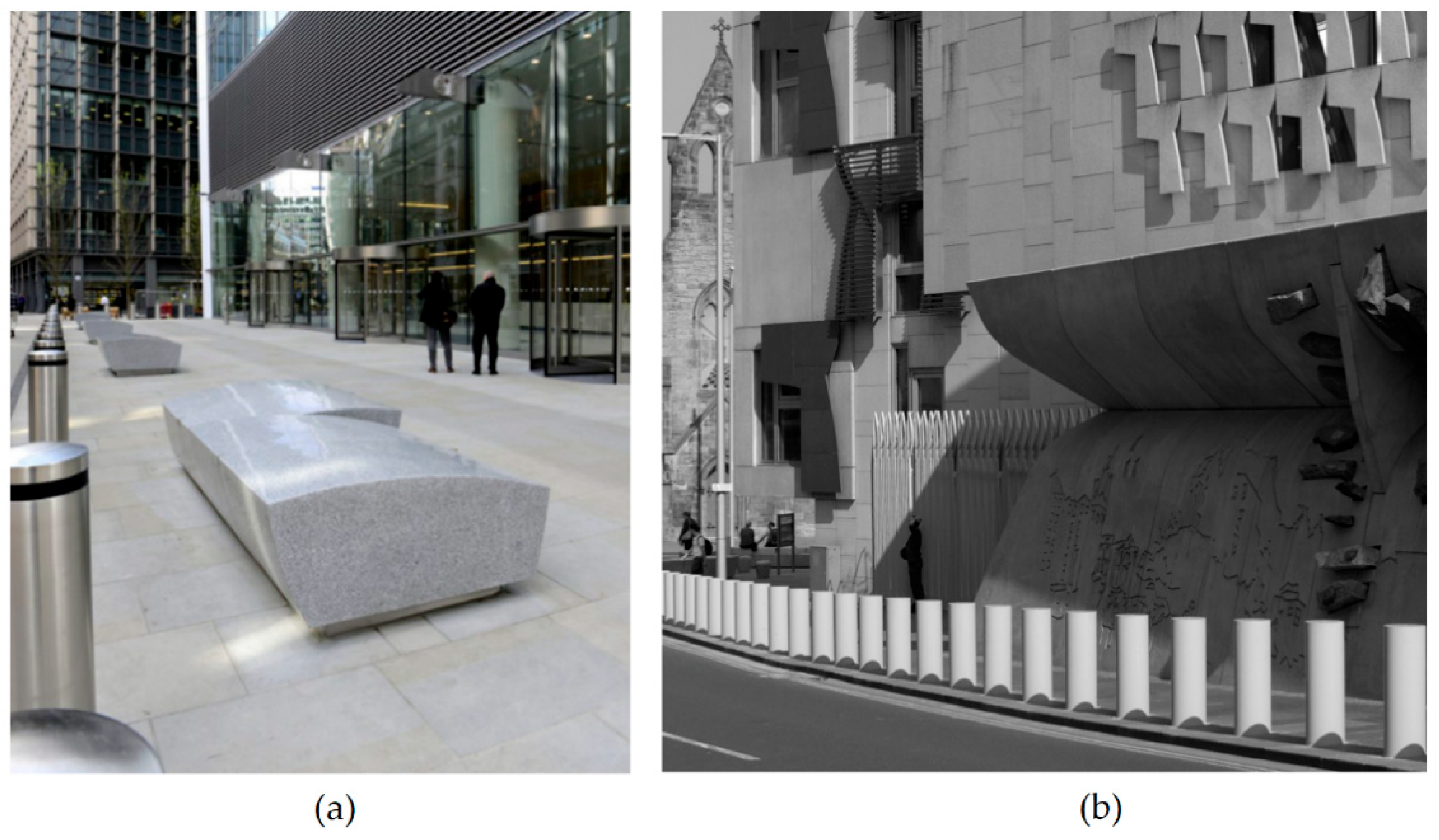
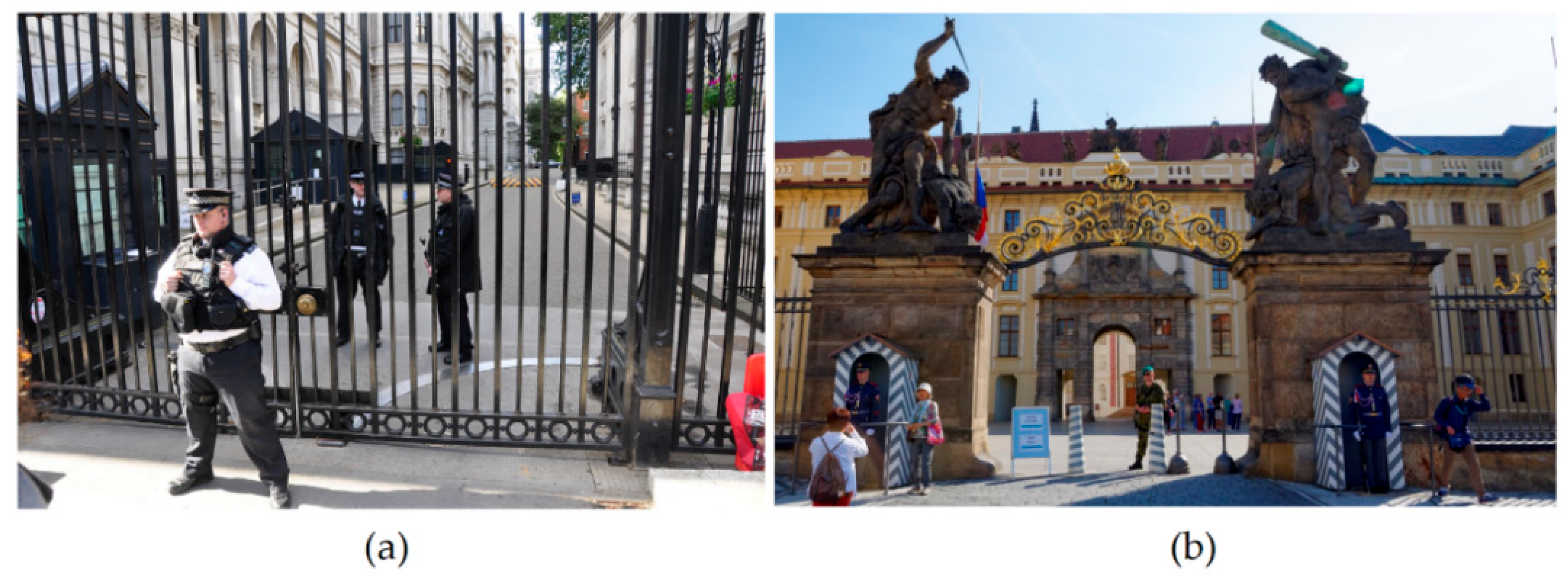
  • Separation of pedestrian and road traffic via, e.g., street furniture such as bollards, flower beds, barriers or lines of trees along the road (Figure 1);
  • Traffic-calming measures such as installation of road humps or obstacles forcing the drivers to “zigzag”;
  • Avoiding long and straight roads which would allow the vehicle to accelerate;
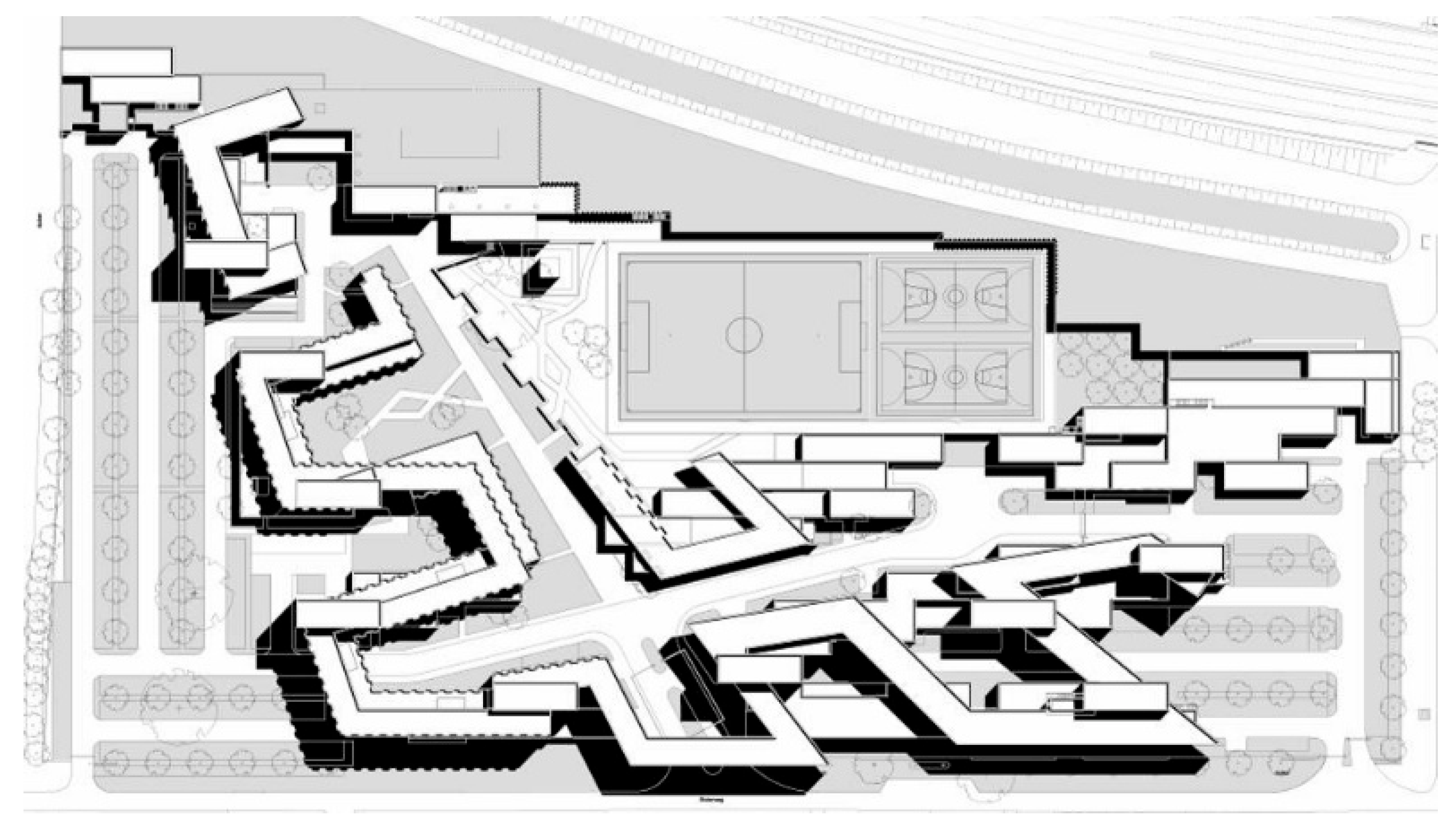
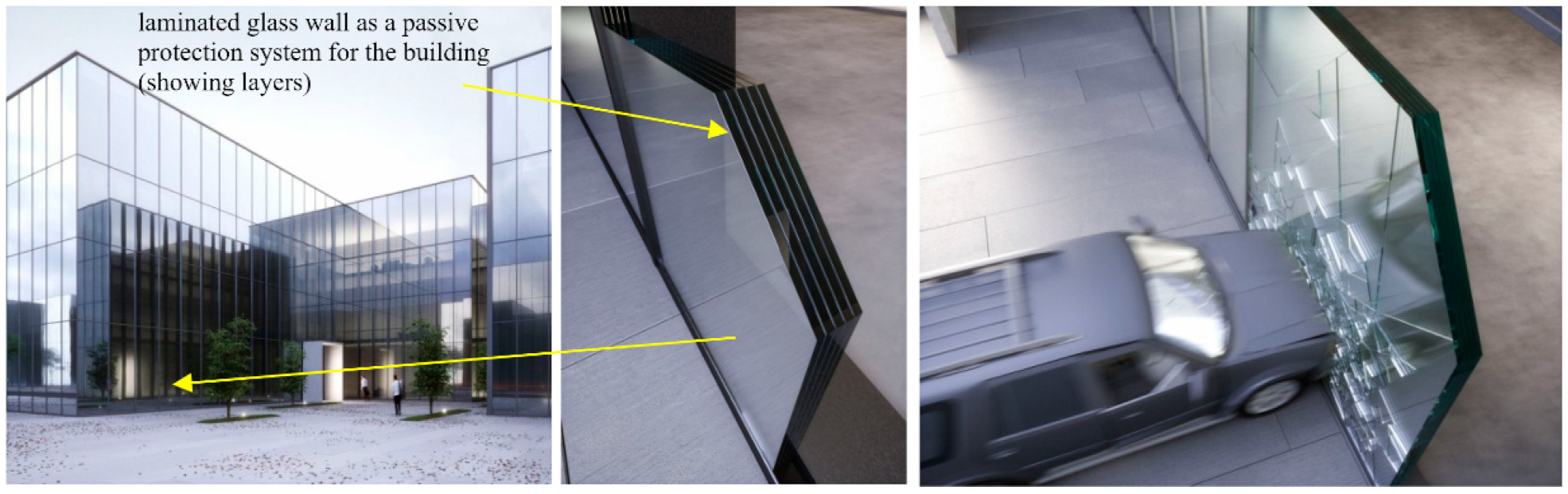
  • Preventing direct access to the key parts of the city via urban layout similar to a shield (Figure 2);
  • Designing buildings with walls acting as shields;
  • Limiting access to individual zones through placement of checkpoints along the main streets, e.g., barriers manned by the police (Figure 3) [64].
One must bear in mind, however, that there are circumstances resulting from legal considerations that are relevant to urban planning or preservation of heritage buildings; these may prohibit the deployment of the protection measures described above. In such cases, to mitigate the impact of attacks, the heritage building may be modernized by deploying a laminated glass wall at the point of contact with the ground (Figure 4). This type of solution can also be employed in modern architecture as many buildings are designed with a fully glazed facade, offering very little resistance to damage.

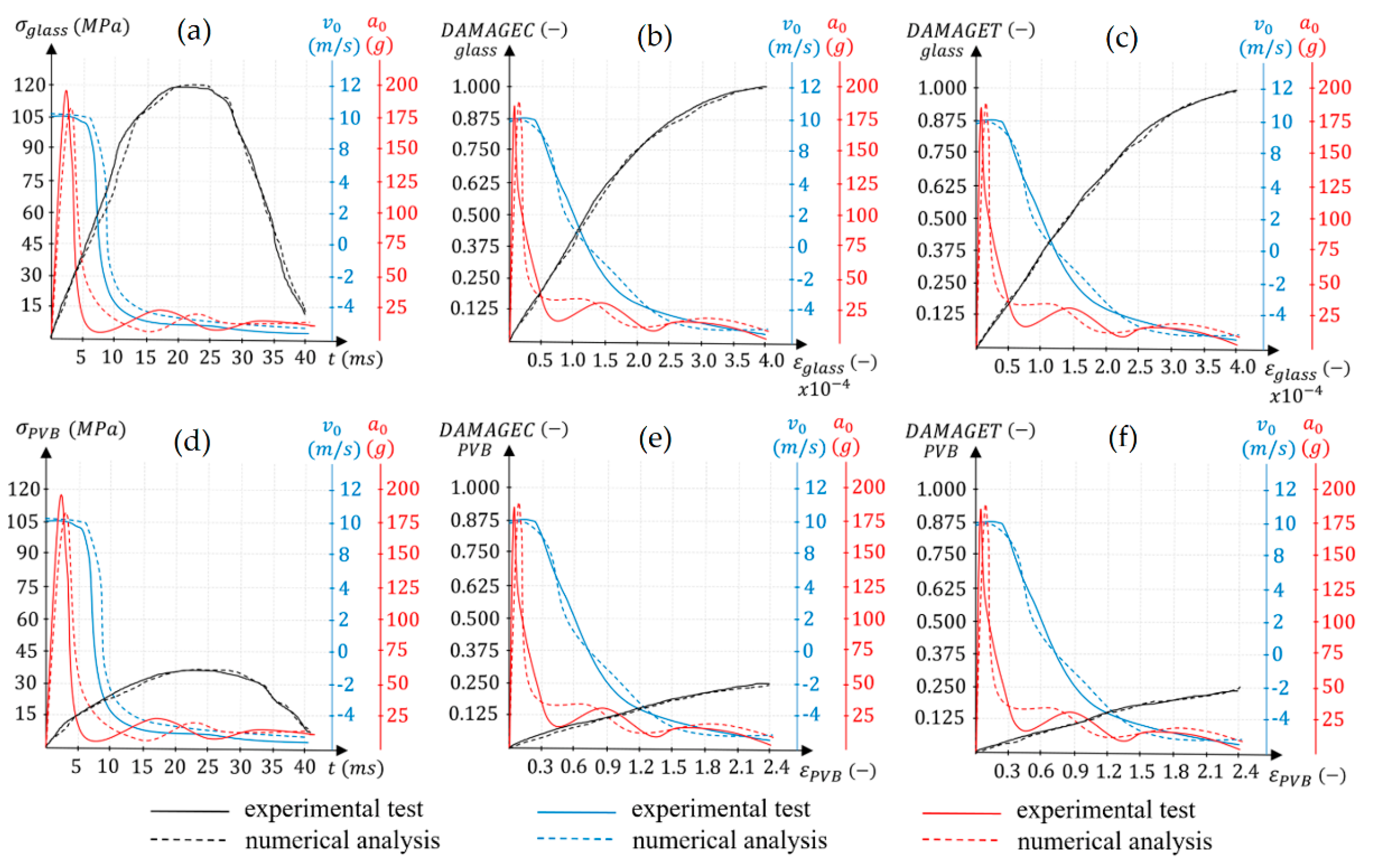
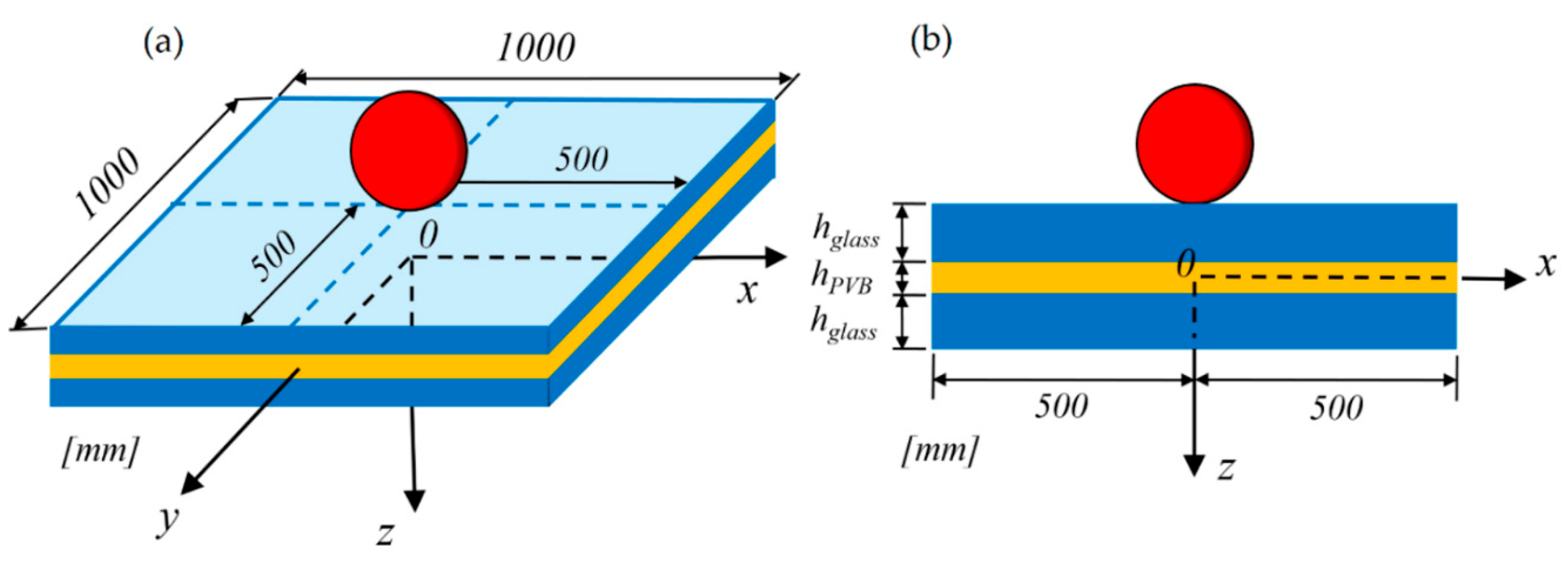
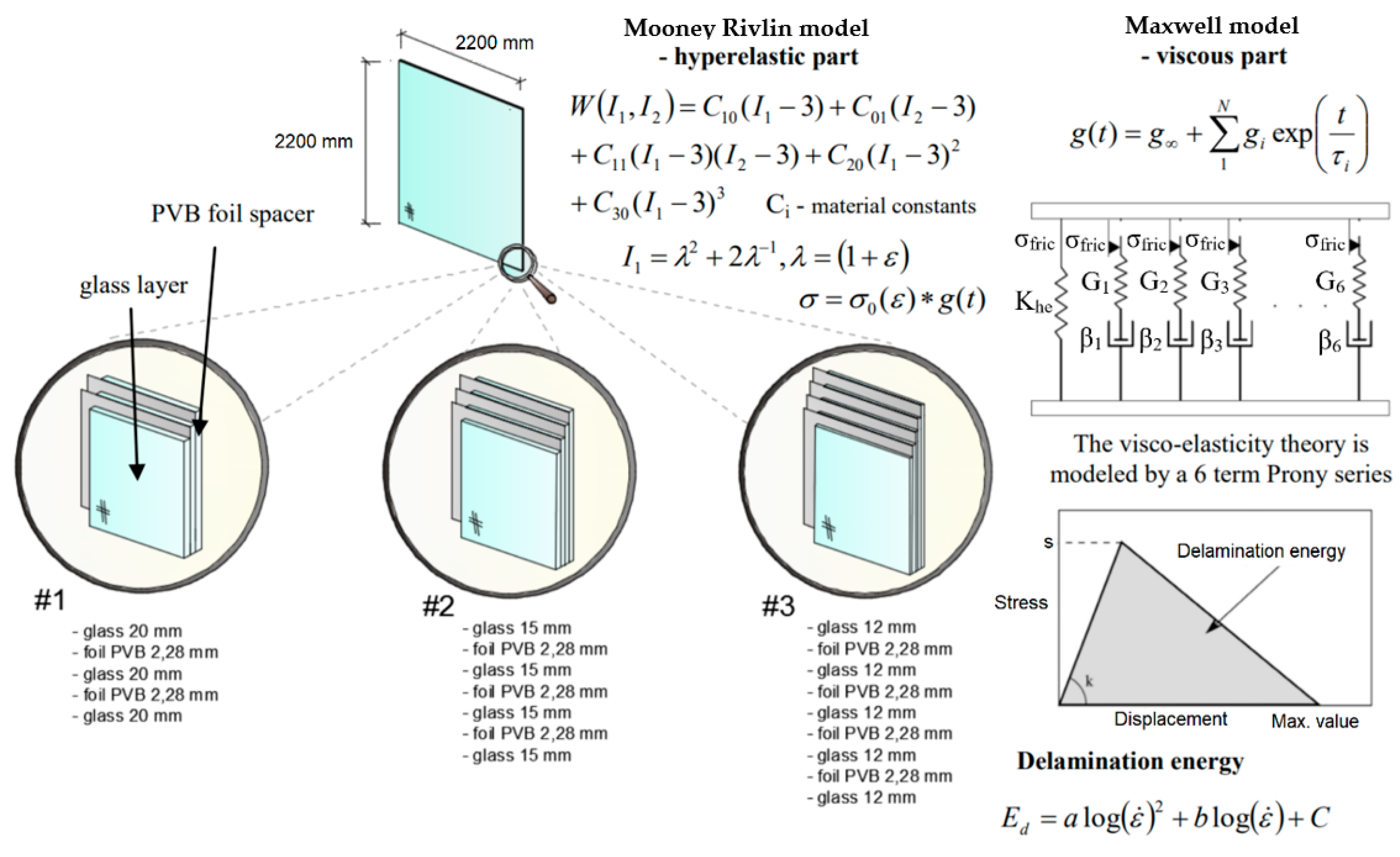
4. Validation of the Parameters of VSG Laminated Glass with PVB Interlayer

The validation of the parameters of VSG glass with a vinyl interlayer was based on data from experimental studies and numerical analyses. Square-shaped laminated glass samples were employed for the purpose of such studies. These samples were subject to dynamic loads of the low-velocity impact type. First, the testing station for carrying out the experiments was built, comprised of a steel frame with an identical shape to the laminated glass sample. The main function of the prepared frame was to effectively secure the sample and to achieve the necessary boundary conditions for each fastened edge. To achieve constant boundary conditions, the samples were secured along each edge with 6 bolts, 24 bolts in total. The geometric model of the laminated glass sample is provided in Figure 5.
The sample dimensions are 1000 × 1000 mm2. The low-velocity impact was initiated using a steel sphere, 85 mm in diameter, weighing 4.96 kg. The sphere was propelled in the direction of the sample using the BiA500 launcher. This allowed us to ensure that the velocity of the sphere in the moment of impact at the center of the sample was equal to 10 m/s. The velocity was measured using laser tachometer sensors. During the tests, a sample with a laminated glass panel was positioned vertically. Due to this, the rebounding phenomena of the metal sphere during the impact could not arise, because the metal sphere fell down after impact. Experimental and numerical studies were carried out on 20 samples. The assumed thickness of each layer was as provided in Table 1.
The examination was recorded with NAC Memre GX-5 high-speed cameras. 3D sensors for motion tracking as well as measuring velocity and acceleration in time were also employed. During the examination, measurements were carried out for stress, strain, displacement, degradation during compression and elongation, as well as impact forces.
Following the experimental study, a numerical examination was carried out in the laboratory with an identical experimental setup. Modeling and numerical simulations were carried out using the LS-DYNA software. Calculations were carried out using the Explicite scheme. The FE model used 8-nodal reduced-integration cubical solid elements with linear shape function type C3D8R. The numerical model included 168,600 solid elements. Regarding the formal usage of the FEM method, a solution convergence analysis was carried out, indicating that the assumed degree of accuracy is achieved with elements with side length of 1 mm. The MAT_32-LAMINATED_GLASS material was assigned to the FE model of the laminated glass sample. For numerical analysis, it was assumed that the sphere is a rigid material, whereas the laminated glass sample is a nonlinear elastic material. The energy release rates of glass are 10 N/m for mode I and 50 N/m for modes II and III. The model for the PVB interlayers was provided by implementing the Mooney–Rivlin constitutive model. The constants assumed for the calculations are A = 1.6 MPa and B = 0.06 MPa, respectively. The parameters of the intrinsic cohesive model for the modelling of adhesion are ψn = ψt = 100 N/m and δn = δt = 0.001 mm. Due to the assumed very small integration time step for motion equations as well as the small, assumed side length of the FEM mesh, the calculation required a significant amount of computing power. To this end, the TRYTON supercomputer available at CI TASK at the Gdansk University of Technology in Poland was employed. TRYTON is the fastest computer in Poland and one of the fastest in the world.
Based on the obtained results, the strength parameters to describe the VSG laminated glass material with PVB foil reinforcement could be developed. These included: mass density (RO), Young’s modulus for glass (EG), Poisson’s ratio for glass (PRG), yield stress for glass (SYG), plastic hardening for glass (ETG), plastic strain at failure for glass (EFG), Young’s modulus for polymer (EP), Poisson’s ratio for polymer (PRP), yield stress for polymer (SYP), plastic hardening for polymer (ETP), and plastic strain at failure for polymer (EFP). The results obtained during the experimental and numerical studies have been compared and are shown in Figure 6 and Figure 7.
It was determined that the destruction and cracking of the laminated glass observed during experimental testing were analogous and identical to the destruction and cracking of the laminated glass achieved during numerical simulations. The observed cracks and fractures coincide with accuracy to 1 mm.
The comparison of results proves that it is possible to validate the parameters of laminated glass efficiently and effectively with PVB interlayers. The results obtained from experimental testing and numerical analyses correspond at virtually every time point. As proven, the maximum difference between the results is lower than 3.1%. The maximum stress occurring in glass σglass was approx. 120 MPa, with corresponding strain εglass equal to approx. 0.0004, at which point the degradation variable during compression DAMAGEC and degradation variable during elongation DAMAGET were equal to 1.000. The maximum stress in the PVB interlayers σPVB was approx. 38 MPa with corresponding strain εPVB equal to approx. 2.4, at which point the degradation variable during compression DAMAGEC and degradation variable during elongation DAMAGET were equal to 0.250.
The obtained results enabled the development of new parameters for laminated glass which can be provided as an input .mat file for MAT_32-LAMINATED_GLASS, available in the materials database of the LS-DYNA software, as provided in Table 2.
Following a legal validation of the laminated glass parameters, a numerical analysis was carried out for the damages of a laminated glass wall at ground level in a building exhibiting a high level of risk associated with terrorist activities, used as a passive protection system for a heritage building.

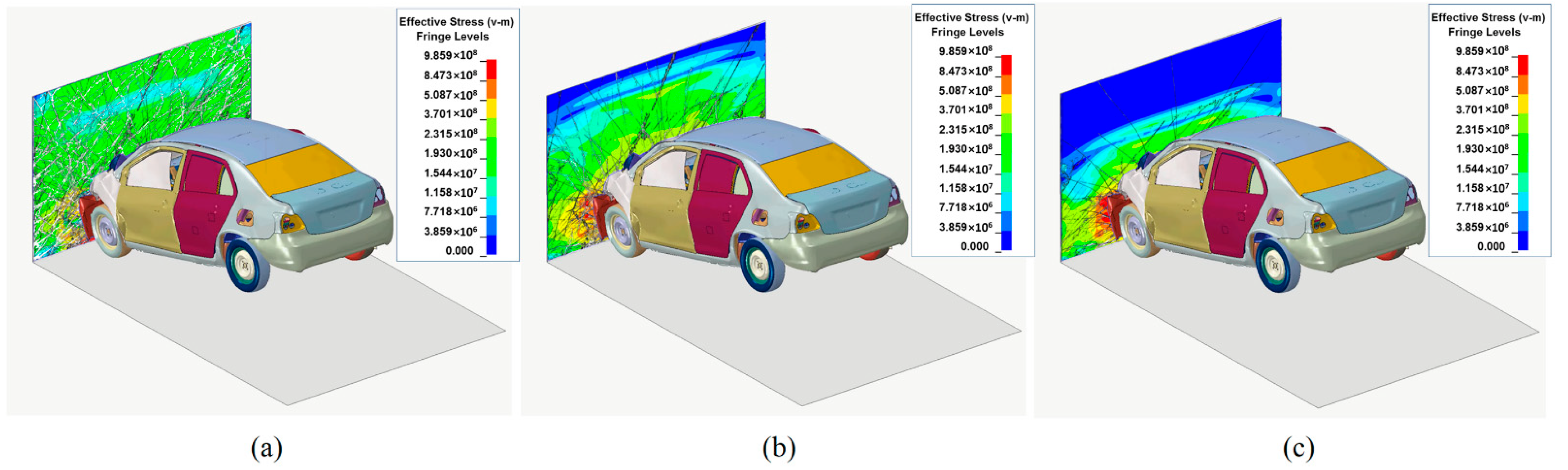
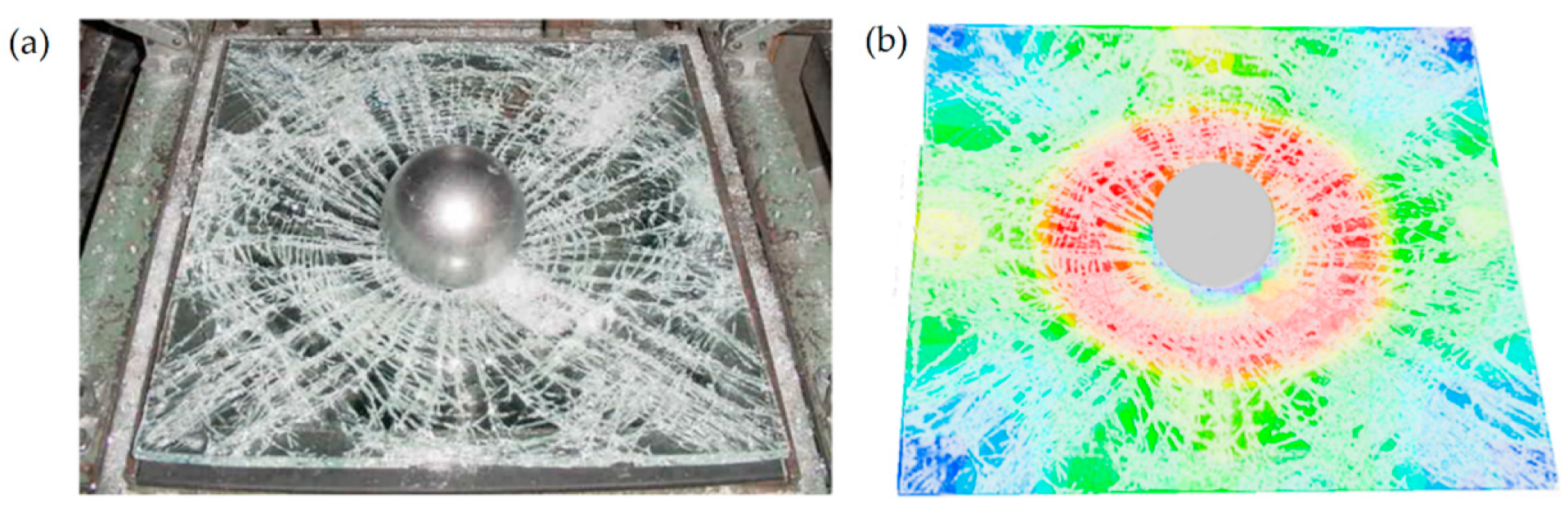
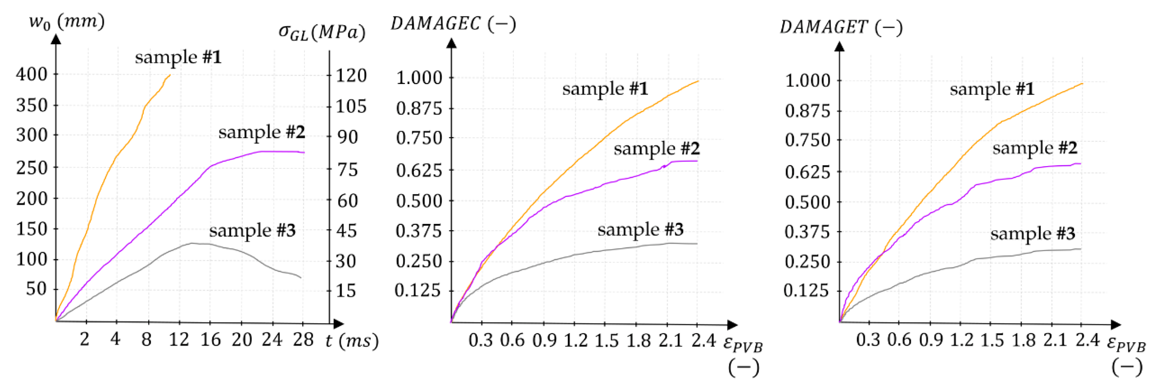
5. Crash Tests of a Vehicle Impact into a Wall of Laminated Glass

Damage prediction for a laminated glass wall was carried out for the historical building of the Maritime Museum at the premises of the Barcelona Royal Shipyard from the Medieval period (Figure 8). The facilities comprise the shipyard building from the Medieval period as well as the former military building featuring Gothic architecture, on the premises of Port Vell in Barcelona. Its construction began in the 13th century under the reign of Peter III of Aragon. The building in the Gothic style was constructed during the first stage in 1283–1328 and in the second stage in the years 1328–1390. The renovation of the shipyard was finished at the beginning of 2013.
The assumed wall for the experiment was rectangular in shape, with a width of 2200 mm and height of 2200 mm, according to the actual dimension of the glazing of the Maritime Museum in Barcelona from the Medieval period. The numerical analysis of the destruction prediction for the wall, built entirely of laminated VSG glass reinforced with PVB foil spacers, was carried out in the LS-DYNA software [65,66,67]. The FE model of the laminated glass wall utilized the MAT_32-LAMINATED_GLASS material, with assigned new parameters as provided in Table 2. The energy release rates of glass are 10 N/m for mode I and 50 N/m for modes II and III. The PVB spacers were represented using the Mooney–Rivlin constitutive model, with the following implemented constants: A = 1.6 MPa and B = 0.06 MPa. The parameters of the intrinsic cohesive model for the modelling of the adhesion are ψn = ψt = 100 N/m and δn = δt = 0.001 mm. The FE model was created using 8-nodal cubical reduced integration solid elements with linear shape function type C3D8R. The FEM mesh dimensions were selected based on convergence analysis. The final assumed mesh dimensions were based on a 1 mm side length corresponding with the x, y and z dimensions. The numerical model was comprised of 1,067,694 solid elements.
The total wall thickness was 60 mm. To evaluate the influence of individual glass layers and the foil spacers of wall strength, the crash tests were carried out for three types of walls, as in Figure 9.
The first wall #1 comprised three VSG glass layers, with single layer thickness equal to 20 mm + 2 PVB spacers with single spacer thickness of 2.28 mm.
The second wall #2 comprised four VSG glass layers, with single layer thickness equal to 15 mm + 3 PVB spacers with single spacer thickness of 2.28 mm.
The third wall #3 comprised five VSG glass layers with single layer thickness equal to 12 mm + 4 PVB spacers with single spacer thickness of 2.28 mm. The thickness of spacer foil is not accounted for in the total wall thickness. Provided below is the mechanical model of the hyper viscous-elastic PVB material used in the numerical study (Figure 9).
For crash tests, a Toyota Corolla make motor vehicle was selected. The numerical model for the car was also fully represented in the LS-DYNA software [65].
Figure 10 and Figure 11 show the results of the numerical simulation for the 3 samples of VSG laminated glass wall reinforced with PVB foil spacers. The vehicle speed was 70 km/h, and the angle of impact was 0°. The wall was affixed on the four sides. Please consider that the stress map key was standardized for the three views of the moment of impact. The reason for this approach was to facilitate the pictorial analysis of the cracking and destruction of the laminated glass wall.
Based on the obtained results, the strength of the VSG laminated glass wall with PVB spacers was estimated depending on the number and thickness of glass layers and vinyl interlayers. In the graphs, the DAMAGEC and DAMAGET parameter value equal to 1.00 stands for complete destruction of the wall (100% destruction).
For sample #1, the maximum stress σ exceeded the limit value of 120 MPa and achieved 328 MPa at strain value ε equal to 2.4, for which the degradation variable during compression DAMAGEC and the degradation variable during elongation DAMAGET were 1.000 and would increase further.
For sample #2, the maximum stress value σ was 82 MPa at strain value ε equal to 2.4, for which the degradation variable during compression DAMAGEC and the degradation variable during elongation DAMAGET were 0.65.
For sample #3, the maximum stress value σ was 20 MPa at strain value ε equal to 2.4, for which the degradation variable during compression DAMAGEC and degradation variable during elongation DAMAGET were 0.32.
It was proven that the use of one additional PVB spacer is sufficient to improve the load bearing capacity of the wall by 300%. However, one needs to consider that additional spacers necessitate an additional layer of glass leading to a sudden increase in weight for the entire wall. When designing laminated glass walls, economic and technical considerations are to be accounted for. Therefore, the greater weight of the wall increases the cost of transportation and installation; furthermore, this necessitates the use of steel mountings for the glass panes used in the wall.

6. Conclusions

Based on the carried out experimental testing and numerical analyses, the obtained results prove the possibility of efficient and effective development of new parameters for laminated glass with PVB interlayers. A parameter validation procedure was carried out and recognized the values as correct. The comparison of the results of experimental testing and numerical analysis indicates a correspondence of 98.1%. Following this, new parameters for laminated glass material were correctly developed and identified. Additionally, the method for their development was determined. The developed parameters represent the mechanical action of the glass cracking together with the destruction of the PVB interlayers beyond the elastic range caused by vehicle impact.
New parameters for the laminated glass material may be implemented as a premade .mat file for the material available in the KEYWORD database under the name MAT_32-LAMINATED_GLASS in the LS-DYNA software.
Considering that accurate analysis of the predicted laminated VGS glass wall with PVB interlayers is a highly advanced and complex undertaking, the methods and numerical calculations based on highly variable dynamic phenomena based on the finite element method are highly effective tools for such an analysis. It has been proven that finite element modeling may describe the geometry and characteristics of laminated glass walls to a high degree of accuracy. The experimental tests and numerical analyses presented in this article together with the obtained results allow the strength of VSG glass walls with PVB interlayers to be estimated, depending on the number and thickness of glass layers and spacers used.
Based on the obtained results, it has been established that the deployment of the passive protection system in the form of a laminated glass wall with sufficient thickness may serve as an effective safeguard from the impact of a motor vehicle. The wall strength is dependent on the number of used PVB interlayers. One additional spacer serves to increase the wall strength by nearly 300%, since the PVB interlayer is a viscous-elastic material which easily transfers shear stress between the individual layers of glass.
Considering the above, we have therefore concluded that the aim of the work has been achieved. The new developed parameters for laminated glass serve as a major contribution and expand the design and analytical possibilities for building construction.
The state of 100% safety is not attainable. Among the main reasons for this is the existence of two incessantly competing social groups. The first group fosters and facilitates an increase of the level of safety, whereas the second group increases the level of danger. Currently, no standards exist for the design of passive protection systems. Current solutions often call for an interdisciplinary collaboration by groups of specialists for the purpose of working out independent rules. Further research into the development of design regulations for safety systems should be treated as a priority. The results of such research should be disseminated among architects and builders to the greatest extent possible.

Author Contributions

Conceptualization, K.G.; methodology, K.G.; software, K.G.; validation, K.G.; formal analysis K.G.; investigation, A.W.; resources, K.G.; data curation, K.G.; writing—original draft preparation, K.G. and A.W.; writing—review and editing K.G. and A.W.; visualization, K.G. and A.W.; supervision, K.G.; project administration, K.G.; funding acquisition, K.G. All authors have read and agreed to the published version of the manuscript.

Funding

The research was financed on the basis of the obtained research and development grant of INVEST-STEEL Sp. z o.o. company with the number IS/0001/2021.

Institutional Review Board Statement

Not applicable.

Informed Consent Statement

Not applicable.

Data Availability Statement

Not applicable.

Conflicts of Interest

The authors declare no conflict of interest.

References

  1. Karwacka, D. The assessment of terrorist threats and their influence on the polish security. Rozpr. Społeczne 2014, 8, 42–50. [Google Scholar]
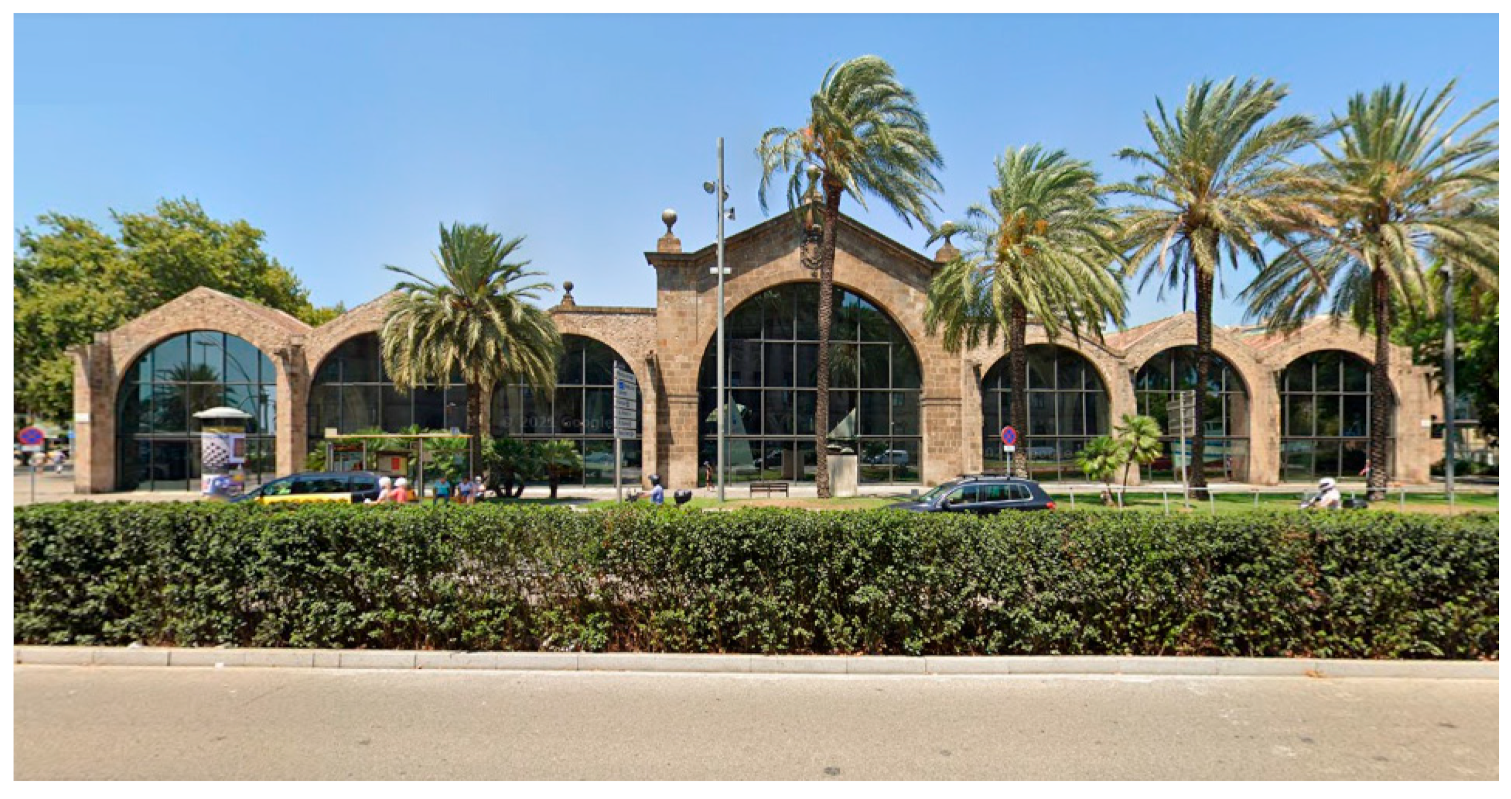
  2. Ibañez, C. History of the Maritime Museum of Barcelona; Maritime Museum of Barcelona: Barcelona, Spain, 2014. [Google Scholar]
  3. Castori, G.; Speranzini, E. Structural analysis of failure behavior of laminated glass. Compos. Part B Eng. 2017, 125, 89–99. [Google Scholar] [CrossRef]
  4. Bois, P.; Kolling, S.; Fassnacht, W. Modelling of safety glass for crash simulation. Comput. Mater. Sci. 2003, 28, 675–683. [Google Scholar] [CrossRef]
  5. Yuan, Y.; Chengliang, X.; Tingni, X.; Yueting, S.; Bohan, L.; Yibing, L. An analytical model for deformation and damage of rectangular laminated glass under low-velocity impact. Compos. Struct. 2017, 176, 833–843. [Google Scholar] [CrossRef]
  6. Yuan, Y.; Tan, P.; Yibing, L. Dynamic structural response of laminated glass panels to blast loading. Compos. Struct. 2017, 182, 579–589. [Google Scholar] [CrossRef] [Green Version]
  7. Chen, S.; Zang, M.; Wang, D.; Yoshimura, S.; Yamada, T. Numerical analysis of impact failure of automotive laminated glass: A review. Compos. Part B Eng. 2017, 122, 47–60. [Google Scholar] [CrossRef]
  8. Linz, P.; Hopper, P.; Arora, H.; Wang, Y.; Smith, D.; Blackman, B.; Dear, J. Delamination properties of laminated glass windows subject to blast loading. Int. J. Impact Eng. 2017, 105, 39–53. [Google Scholar] [CrossRef] [Green Version]
  9. Zielińska, M.; Misiewicz, J. Structural aspects in restoring historical buildings for re-use: The case of a tenement building on Staromiejska Street in Olsztyn. J. Herit. Conserv. 2016, 46, 100–109. [Google Scholar]
  10. CEN/TS 19100; Design of Glass Structures. European Committee for Standardization: Brussels, Belgium, 2021; pp. 1–35.
  11. Sable, L.; Skukis, E.; Japins, G.; Kalnins, K. Correlation between numerical and experimental tests of laminated glass panels with visco-elastic interlayer. Procedia Eng. 2017, 172, 945–952. [Google Scholar] [CrossRef]
  12. Aenlle, M.L.; Pelayo, F.; Ismael, G. Calculation of displacements and stresses in laminated glass beams under dynamic loading using an effective Young modulus. Procedia Eng. 2017, 199, 1405–1410. [Google Scholar] [CrossRef]
  13. Chen, X.; Chan, A.H.C. Modelling impact fracture and fragmentation of laminated glass using the combined finite-discrete element method. Int. J. Impact Eng. 2018, 112, 15–29. [Google Scholar] [CrossRef]
  14. Mohagheghian, I.; Wang, Y.; Zhou, J.; Yu, L.; Guo, X.; Yan, Y.; Charalambides, M.N.; Dear, J. Deformation and damage mechanisms of laminated glass windows subjected to high velocity soft impact. Int. J. Solids Struct. 2017, 109, 46–62. [Google Scholar] [CrossRef]
  15. Pelayo, F.; Lopez-Aenlle, M.; Ismael, G.; Fernandez-Canteli, A. Buckling of multilayered laminated glass beam: Validation of the effective thickness concept. Compos. Struct. 2017, 169, 2–9. [Google Scholar] [CrossRef] [Green Version]
  16. Peng, Y.; Yang, J.; Deck, C.; Wilinger, R. Finite element modeling of crash test behavior for windshield laminated glass. Int. J. Impact Eng. 2013, 57, 27–35. [Google Scholar] [CrossRef]
  17. Jasiński, A. Protecting public spaces against vehicular terrorist attacks. Tech. Trans.—Archit. Urban Plan. 2018, 2, 47–56. [Google Scholar]
  18. Łodygowski, T.; Sielicki, P.; Sumelka, W.; Peksa, P.; Olejnik, M.; Puk, K. Selected aspects of the safety of people, buildings and property by passive protection systems. Logistyka 2014, 5, 926–939. [Google Scholar]
  19. Chen, S.; Zang, M.; Wang, D.; Zheng, Z.; Zhao, C. Finite element modelling of impact damage in polyvinyl butyral laminated glass. Compos. Struct. 2016, 138, 1–11. [Google Scholar] [CrossRef]
  20. Eisenträger, J.; Naumenko, K.; Altenbach, H.; Meenen, J. A user-defined finite element for laminated glass panels and photovoltaic modules based on a layerwise theory. Compos Struct. 2015, 133, 265–277. [Google Scholar] [CrossRef]
  21. Foraboschi, P. Analytical model for laminated-glass plate. Compos. Part B Eng. 2012, 43, 2094–2106. [Google Scholar] [CrossRef]
  22. Lasowicz, N.; Kwiecień, A.; Jankowski, R. Experimental Study on the Effectiveness of Polyurethane Flexible Adhesive in Reduction of Structural Vibrations. Polymers 2020, 12, 2364. [Google Scholar] [CrossRef]
  23. Foraboschi, P. Hybrid laminated-glass plate: Design and assessment. Compos. Struct. 2013, 106, 250–263. [Google Scholar] [CrossRef]
  24. Grębowski, K.; Zielińska, M. Dynamic analysis of the railway bridges in Poland with regards to high-speed trains passage adjustment. In Proceedings of the 5th International Multidisciplinary Scientific Conference on Social Sciences & Arts SGEM: Urban Planning, Architecture and Design, Albena, Bulgaria, 26 August–1 September 2018; pp. 765–772. [Google Scholar] [CrossRef]
  25. Overend, M.; Butchart, C.; Lambert, H.; Prassas, M. The mechanical performance of laminated hybrid-glass units. Compos. Struct. 2014, 110, 163–173. [Google Scholar] [CrossRef]
  26. Bennison, S.J.; Jagota, A.; Smith, C.A. Fracture of glass/poly (vinyl butyral) (Butacite) laminates in biaxial flexure. J. Am. Ceram. Soc. 1999, 82, 1761–1770. [Google Scholar] [CrossRef]
  27. Larcher, M.; Solomos, G.; Casadei, F.; Gebbeken, N. Experimental and numerical investigations of laminated glass subjected to blast loading. Int. J. Impact Eng. 2012, 39, 42–50. [Google Scholar] [CrossRef]
  28. Xu, J.; Li, Y.; Liu, B.; Zhu, M.; Ge, D. Experimental study on mechanical behavior of PVB laminated glass under quasi-static and dynamic loadings. Compos. Part B Eng. 2011, 42, 302–318. [Google Scholar] [CrossRef]
  29. Asik, M.; Dural, E.; Yetmez, M.; Uzhan, T. A mathematical model for the behavior of laminated uniformly curved glass beams. Compos. Part B Eng. 2014, 58, 593–604. [Google Scholar] [CrossRef]
  30. Biolzi, L.; Cattaneo, S.; Rosati, G. Progressive damage and fracture of laminated glass beams. Constr. Build. Mater. 2010, 24, 577–584. [Google Scholar] [CrossRef]
  31. Xu, J.; Sun, Y.; Liu, B.; Zhu, M.; Yao, X.; Yan, Y.; Li, Y.; Chen, X. Experimental and macroscopic investigation of dynamic crack patterns in PVB laminated glass sheets subject to light-weight impact. Eng. Fail. Anal. 2011, 18, 1605–1612. [Google Scholar] [CrossRef]
  32. Chen, J.; Xu, J.; Liu, B.; Yao, X.; Li, Y. Quantity effect of radial cracks on the cracking propagation behavior and the crack morphology. PLoS ONE 2014, 9, e98196. [Google Scholar] [CrossRef]
  33. Aenlle, M.; Pelayo, F.; Ismael, G. An effective thickness to estimate stresses in laminated glass beams under dynamic loadings. Compos. Part B Eng. 2015, 82, 1–12. [Google Scholar] [CrossRef] [Green Version]
  34. Chen, J.; Xu, J.; Yao, X.; Xu, X.; Liu, B.; Li, Y. Different driving mechanisms of in-plane cracking on two brittle layers of laminated glass. Int. J. Impact Eng. 2014, 69, 80–95. [Google Scholar] [CrossRef]
  35. Przewłócki, J.; Zielińska, M.; Grębowski, K. Numerical Modelling of Connections Between Stones in Foundations of Historical Buildings. IOP Conf. Ser. Earth Environ. Sci. 2017, 95, 1–8. [Google Scholar] [CrossRef]
  36. Sukumar, N.; Moes, N.; Moran, B.; Belytschko, T. Extended finite element method for three-dimensional crack modelling. Int. J. Numer. Methods Eng. 2000, 48, 1549–1570. [Google Scholar] [CrossRef]
  37. Zielińska, M.; Rucka, M. Imaging of Increasing Damage in Steel Plates Using Lamb Waves and Ultrasound Computed Tomography. Materials 2021, 14, 5114. [Google Scholar] [CrossRef]
  38. Timmel, M.; Kolling, S.; Osterrieder, P.; Du Bois, P. A finite element model for impact simulation with laminated glass. Int. J. Impact Eng. 2007, 34, 1465–1478. [Google Scholar] [CrossRef]
  39. Hidallana-Gamage, H.D.; Thambiratnam, D.P.; Perera, N.J. Failure analysis of laminated glass panels subjected to blast loads. Eng. Fail. Anal. 2014, 36, 14–29. [Google Scholar] [CrossRef] [Green Version]
  40. Pyttel, T.; Liebertz, H.; Cai, J. Failure criterion for laminated glass under impact loading and its application in finite element simulation. Int. J. Impact Eng. 2011, 38, 252–263. [Google Scholar] [CrossRef]
  41. Shutov, A.I.; Frank, A.N.; Novikov, I.A.; Ostapko, A.S.; Bonchuk, A.S. Testing laminated glass for impact resistance. Glass Ceram. 2004, 61, 67–69. [Google Scholar] [CrossRef]
  42. Zhang, X.; Hao, H.; Ma, G. Laboratory test and numerical simulation of laminated glass window vulnerability to debris impact. Int. J. Impact Eng. 2013, 55, 49–62. [Google Scholar] [CrossRef]
  43. Zhang, X.; Hao, H.; Ma, G. Parametric study of laminated glass window response to blast loads. Eng. Struct. 2013, 56, 1707–1717. [Google Scholar] [CrossRef]
  44. Galuppi, L.; Manara, G.; Carfagni, G. Practical expressions for the design of laminated glass. Compos. Part B Eng. 2013, 45, 1677–1688. [Google Scholar] [CrossRef]
  45. Xu, J.; Li, Y. Study of damage in windshield glazing subject to impact by a pedestrian’s head. Proc. Inst. Mech. Eng. Part D J. Automob. Eng. 2009, 223, 77–84. [Google Scholar] [CrossRef]
  46. Taraszkiewicz, A.; Grębowski, K.; Taraszkiewicz, K.; Przewłócki, J. Medieval Bourgeois Tenement Houses as an Archetype for Contemporary Architectural and Construction Solutions: The Example of Historic Downtown Gdańsk. Buildings 2021, 11, 80. [Google Scholar] [CrossRef]
  47. Xu, W.; Zang, M. Four-point combined DE/FE algorithm for brittle fracture analysis of laminated glass. Int. J. Solids Struct. 2014, 51, 1890–1900. [Google Scholar] [CrossRef] [Green Version]
  48. Taraszkiewicz, A.; Grębowski, K.; Taraszkiewicz, K.; Przewłócki, J. Contemporary Architectural Design in the Context of Historic Remains: The Case of the Old City of Gdańsk. Herit. Soc. 2022, 1, 1–19. [Google Scholar] [CrossRef]
  49. Gao, W.; Zang, M. The simulation of laminated glass beam impact problem by developing fracture model of spherical DEM. Eng. Anal. Bound. Elem. 2014, 42, 2–7. [Google Scholar] [CrossRef]
  50. Xu, J.; Li, Y.; Chen, X.; Yan, Y.; Ge, D.; Zhu, M.; Liu, B. Characteristics of windshield cracking upon low-speed impact: Numerical simulation based on the extended finite element method. Comput. Mater. Sci. 2010, 48, 582–598. [Google Scholar] [CrossRef]
  51. Chen, S.; Zang, M.; Xu, W. A three-dimensional computational framework for impact fracture analysis of automotive laminated glass. Comput. Methods Appl. Mech. Eng. 2015, 294, 72–99. [Google Scholar] [CrossRef]
  52. Hidallana-Gamage, H.D.; Thambiratnam, D.P.; Perera, N.J. Influence of interlayer properties on the blast performance of laminated glass panels. Constr. Build. Mater. 2015, 98, 502–518. [Google Scholar] [CrossRef]
  53. Hidallana-Gamage, H.D.; Thambiratnam, D.P.; Perera, N.J. Numerical modelling and analysis of the blast performance of laminated glass panels and the influence of material parameters. Eng. Fail. Anal. 2014, 45, 65–84. [Google Scholar] [CrossRef]
  54. Kevin, C.; Van Doormaal, A.; Haberacker, C.; Hüsken, G.; Larcher, M.; Saarenheimo, A.; Solomos, G.; Stolz, A.; Thamie, L.; Bedon, C. Numerical Simulations for Classification of Blast Loaded Laminated Glass: Possibilities, Limitations and Recommendations; European Reference Network for Critical Infrastructure Protection (Erncip): Ispra, Italy, 2014; pp. 1–39. [Google Scholar]
  55. Dharani, L.R.; Wei, J.; Yu, J.; Minor, J.E.; Behr, R.A.; Kremer, P.A. Laminated architectural glass subjected to blast impact loading. Am. Ceram. Soc. Bull. 2005, 84, 42–44. [Google Scholar]
  56. Bedon, C.; Zhang, X.; Santos, F.; Honfi, D.; Kozłowski, M.; Arrigoni, M.; Figuli, L.; Lange, D. Performance of structural glass facades under extreme loads—Design methods, existing research, current issues and trends. Constr. Build. Mater. 2018, 163, 921–937. [Google Scholar] [CrossRef]
  57. PN-EN 1991-1-7:2008/NA:2015-02; Eurokod 1. Polski Komitet Normalizacyjny: Warszawie, Poland, 2015.
  58. UFC 4-023-03; Design of Buildings to Resist Progressive Collapse. Department of Defense United States of America: Washington, DC, USA, 2016; Volume 3, pp. 1–245.
  59. CEN/TS 19100-1; Basis of Design and Materials. iTeh, Inc.: Newark, NJ, USA, 2021.
  60. CEN/TS 19100-2; Design of out of Plane Loaded Glass Components. iTeh, Inc.: Newark, NJ, USA, 2021.
  61. CEN/TS 19100-3; Design of in Plane Loaded Glass Components and Their Mechanical Joints. iTeh, Inc.: Newark, NJ, USA, 2021.
  62. Newmann, O. Defensible Space: Crime Prevention through Urban Design; Macmillan Publisher: New York, NY, USA, 1972; pp. 1–264. [Google Scholar]
  63. Jeffery, C. Behavior Control Techniques and Criminology; Youth Development Ecology Workshop at the University of Hawaii: Honolulu, HI, USA, 1975. [Google Scholar]
  64. Łodygowski, T. Wybrane aspekty bezpieczeństwa ludzi, budynków i mienia poprzez systemy ochrony pasywnej. Logistyka 2014, 5, 927–930. [Google Scholar]
  65. Grębowski, K.; Rucka, M.; Wilde, K. Non-Destructive Testing of a Sport Tribune under Synchronized Crowd-Induced Excitation Using Vibration Analysis. Materials 2019, 12, 2148. [Google Scholar] [CrossRef] [PubMed] [Green Version]
  66. Przewłócki, J.; Grębowski, K.; Zielińska, M. Analysis of the Load-Bearing Capacity of Historical Foundations in the Context of the Quality of Mortar Used. J. Herit. Conserv. 2021, 66, 92–105. [Google Scholar]
  67. Grębowski, K.; Hirsz, M.; Wilde, K.; Nadolny, A. Parametric analysis of Istanbul’s Ring Road viaduct for three levels of seismic load. Adv. Mech. Theor. Comput. Interdiscip. 2016, 207–211. [Google Scholar] [CrossRef]
Figure 1. Anti-terrorist bollards and concrete barriers installed at the entrance to the building: (a) 20 Fenchurch Street in London, (b) The Scottish Parliament Building; phot. B&E Group, 2018.
Buildings 12 00988 g001
Figure 2. The concept of compact urban development for the Royal Military Police District Schiphol Danemark; source: Zvi Hecker Archive, Berlin, 2005.
Buildings 12 00988 g002
Figure 3. Establishing safety zones via checkpoints: (a) the seat of the British Prime Minister in London. (b) The Hradčany castle complex in Prague; phot. ATG Access Ltd., 2015.
Buildings 12 00988 g003
Figure 4. An example of a possible deployment of a laminated glass wall as a passive protection system with a fully glazed facade.
Buildings 12 00988 g004
Figure 5. Schematic view of laminated glass under impact of a rigid spherical projectile: (a) three-dimensional view; (b) front view.
Buildings 12 00988 g005
Figure 6. Results comparison for (a) experimental tests and (b) numerical analyses for samples from Test no. 1.
Buildings 12 00988 g006
Figure 7. Comparison of results of experimental testing and numerical analyses based on the carried-out interpolation of result values for 20 attempts of destructive testing of samples during Test no. 1: (a) graph stresses σglass in time t; (b) graph DAMAGEC in strain εglass; (c) graph DAMAGET in strain εglass; (d) graph stresses σPVB in time t; (e) graph DAMAGEC in strain εPVB; (f) graph DAMAGET in strain εPVB.
Buildings 12 00988 g007
Figure 8. An example application of a laminated glass wall on a historic building of the Maritime Museum of the Barcelona Shipyard from the Medieval period–January 2022.
Buildings 12 00988 g008
Figure 9. The mechanical model of the hyper viscous-elastic PVB material.
Buildings 12 00988 g009
Figure 10. Results of the destruction of the VSG wall with PVB spacers: (a) sample #1, 3 layers of VSG glass, single layer thickness: 20 mm + 2 PVB foil spacers with single spacer thickness of 2.28 mm, (b) sample #2, 4 VSG glass layers, single layer thickness: 15 mm + 3 PVB foil spacers with single spacer thickness 2.28 mm, (c) sample #3, 5 VSG glass layers with single layer thickness: 12 mm + 4 PVB foil spacers with single spacer thickness 2.28 mm.
Buildings 12 00988 g010
Figure 11. Comparison of the results of numerical simulations for the destruction of the VSG wall with PVB spacers for sample #1, sample #2, and sample #3.
Buildings 12 00988 g011
Table 1. Thicknesses of individual laminated glass panel layers.
Test No. Interlayer
Material
Thickness (mm)
hglass + hPVB + … + hglass + hPVB
Impact
Velocity (m/s)
1PVB20 + 2.28 + 20 + 2.28 + 2010.00
Table 2. New parameters of VSG glass reinforced with PVB interlayers.
ROEGPRGSYGETGEFGEPPRPSYPETPEFP
Mass densityYoung’s modulus for glassPoisson’s ratio for glassYield stress for glassPlastic hardening for glassPlastic strain at failure for glassYoung’s modulus for polymerPoisson’s ratio for polymerYield stress for polymerPlastic hardening for polymerPlastic strain at failure for polymer
kg/m3GPa-MPaGPa-GPa-MPaMPa-
25001000.227120600.00040.2530.435383.262.4
Publisher’s Note: MDPI stays neutral with regard to jurisdictional claims in published maps and institutional affiliations.

