
Comparative Life Cycle Analysis of Timber, Steel and Reinforced Concrete Portal Frames: A Theoretical Study on a Norwegian Industrial Building


Abstract
:1. Introduction
2. Methodology
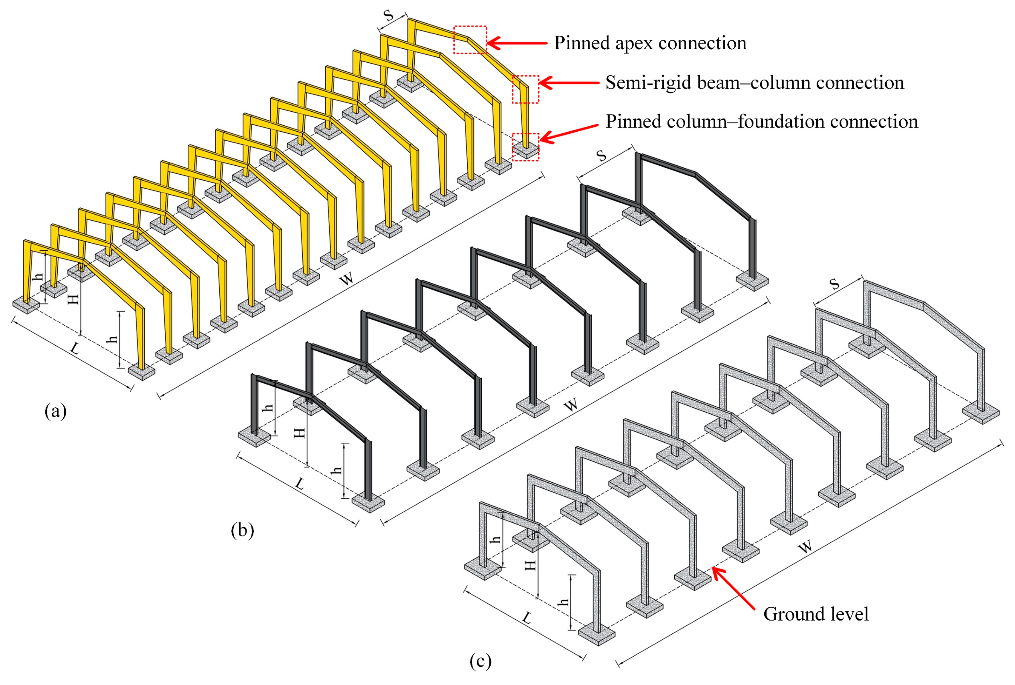
2.1. Structural System and Layout
2.2. Assumptions and Simplifications
- For all frames, the design is performed such that the clear height at the corner is 5 m;
- All secondary elements were not included in the structural design; therefore, their own weight was assumed to be 0.30 kN/m2 for all frames, this is to facilitate the comparison;
- All frames are subjected to a uniform live load of 0.40 kN/m2 at the roof as recommended by EN1991-1-1 [20];
- The peak wind pressure is 0.65 kN/m2, this corresponds to the Oslo area ( with terrain category of II as defined by EN1991-1-4 [21];
- The characteristic snow load is 2.80 kN/m2, this corresponds to the Oslo area with altitude of less than 100 m EN1991-1-3 [22];
- The columns were assumed pinned to the foundations for timber, steel and concrete frames;
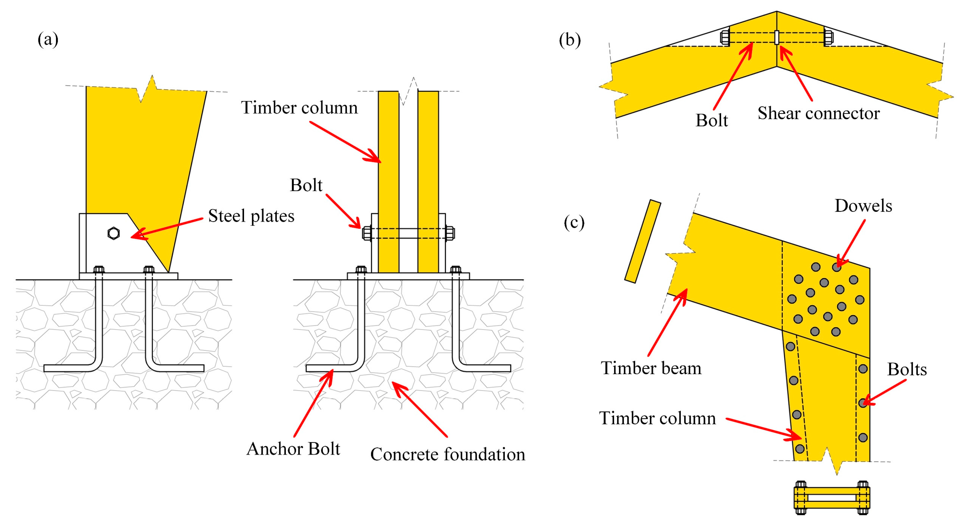
- The corner and apex connections of steel and concrete frames were assumed rigid. The apex connection of timber frames was assumed pinned, and the corner connection of timber frames was assumed semi-rigid (refer to Figure 2);
- The foundations of all frames are isolated footing and made of reinforced concrete;
- The concrete used in reinforced concrete frames and the foundations of all frames is C30/C37 (30 MPa cylinder strength or 37 MPa cube strength) and the reinforcing bars are of quality B500C available in the Norwegian market (500 MPa yield strength). The maximum aggregate size is 20 mm. The exposure class is XC3. The design life is 50 years. The previous assumptions result in a minimum cover of 35 mm, a maximum water content of 0.55, and a minimum cement content of 300 kg/m3 [23];
- The structural steel used in the beams and columns of the steel portal frames is of quality S460, available in the Norwegian market (460 MPa yield strength);
- The timber used in the beams and columns of the timber frames is glulam of strength class GL30c defined by EN14080 [24];
- The steel dowels and bolts used in the connections of timber frames were assumed of a strength class 8.8 (800 MPa ultimate strength and 640 MPa yield strength) as defined by ISO 898 [25];
- The structural steel used in the connections of the timber frames is of quality S460 available in the Norwegian market (460 MPa yield strength);
- The load combination used in the design of all frames is the fundamental load combination defined by equation 6.10 in EN1990 [26] ( for live load and snow load, and 0.60 for wind load, as defined by the Norwegian National Annex);
- All frames of the three materials are dimensioned to meet similar load carrying capacity;
- The structural design and the calculation of quantities were performed only for the main structural system, no secondary structural elements (purlins, slabs, etc.) or covering were included.
2.3. LCA Background, Functional Unit, and System Boundaries
2.4. Calculation of Emissions
3. Structural Design and Quantities
3.1. Timber Frames
3.2. Steel Frames
3.3. Reinforced Concrete Frames
4. Results, Discussion, and Limitations
5. Conclusions and Future Work
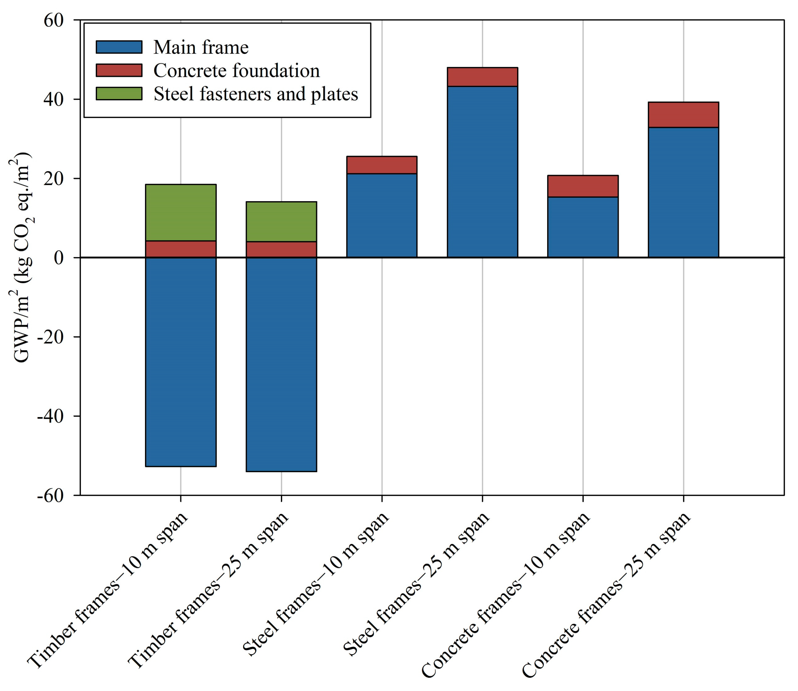
- Considering the total GWP/m2 (main frames, foundations, and steel fasteners and plates), the steel frames have a GWP/m2 that is higher than the concrete frames and much higher than the timber frames for both the 10-m span and 25-span frames;
- Considering only the foundations, the timber frames have the lowest GWP/m2, while the concrete frames have the highest GWP/m2 for both the 10-m span and 25-span frames.
Author Contributions
Funding
Data Availability Statement
Conflicts of Interest
References
- Department of Economic and Social Affairs, United Nations. Population Dynamics, World Population Prospects 2019. Available online: https://population.un.org/wpp/Graphs/Probabilistic/POP/TOT/900 (accessed on 25 January 2022).
- IPCC. Climate Change 2014: Mitigation of Climate Change. Contribution of Working Group III to the Fifth Assessment Report of the Intergovernmental Panel on Climate; Cambridge University Press: Cambridge, UK; New York, NY, USA, 2014. [Google Scholar]
- IPCC. Summary for Policymakers. In Global Warming of 1.5 °C. An IPCC Special Report on the Impacts of Global Warming of 1.5 °C Above Pre-Industrial Levels and Related Global Greenhouse Gas Emission Pathways, in the Context of Strengthening the Global Response to the Threat of Climate Change, Sustainable Development, and Efforts to Eradicate Poverty; World Meteorological Organization: Geneva, Switzerland, 2018; 32p. [Google Scholar]
- Liu, Y.; Guo, H.; Sun, C.; Chang, W.S. Assessing cross laminated timber (CLT) as an alternative material for mid-rise residential buildings in cold regions in China-A life-cycle assessment approach. Sustainability 2016, 8, 1047. [Google Scholar] [CrossRef] [Green Version]
- Guo, H.; Liu, Y.; Meng, Y.; Huang, H.; Sun, C.; Shao, Y. A Comparison of the energy saving and carbon reduction performance between reinforced concrete and cross-laminated timber structures in residential buildings in the severe cold region of China. Sustainability 2017, 9, 1426. [Google Scholar] [CrossRef] [Green Version]
- Chen, Z.; Gu, H.; Bergman, R.D.; Liang, S. Comparative life-cycle assessment of a high-rise mass timber building with an equivalent reinforced concrete alternative using the athena impact estimator for buildings. Sustainability 2020, 12, 4708. [Google Scholar] [CrossRef]
- Eliassen, A.R.; Faanes, S.; Bohne, R.A. Comparative LCA of a concrete and steel apartment building and a cross laminated timber apartment building. IOP Conf. Ser. Earth Environ. Sci. 2019, 323, 012017. [Google Scholar] [CrossRef] [Green Version]
- Liang, S.; Gu, H.; Bergman, R.; Kelley, S.S. Comparative life-cycle assessment of a mass timber building and concrete alternative. Wood Fiber Sci. 2020, 52, 217–229. [Google Scholar] [CrossRef]
- Sandanayake, M.; Lokuge, W.; Zhang, G.; Setunge, S.; Thushar, Q. Greenhouse gas emissions during timber and concrete building construction—A scenario based comparative case study. Sustain. Cities Soc. 2018, 38, 91–97. [Google Scholar] [CrossRef] [Green Version]
- Skullestad, J.L.; Bohne, R.A.; Lohne, J. High-rise Timber Buildings as a Climate Change Mitigation Measure—A Comparative LCA of Structural System Alternatives. Energy Procedia 2016, 96, 112–123. [Google Scholar] [CrossRef] [Green Version]
- Dodoo, A.; Gustavsson, L.; Sathre, R. Lifecycle carbon implications of conventional and low-energy multi-storey timber building systems. Energy Build. 2014, 82, 194–210. [Google Scholar] [CrossRef]
- Dodoo, A.; Gustavsson, L.; Sathre, R. Carbon implications of end-of-life management of building materials. Resour. Conserv. Recycl. 2009, 53, 276–286. [Google Scholar] [CrossRef]
- Gong, X.; Nie, Z.; Wang, Z.; Cui, S.; Gao, F.; Zuo, T. Life cycle energy consumption and carbon dioxide emission of residential building designs in Beijing: A comparative study. J. Ind. Ecol. 2012, 16, 576–587. [Google Scholar] [CrossRef]
- Börjesson, P.; Gustavsson, L. Greenhouse gas balances in building construction: Wood versus concrete from life-cycle and forest land-use perspectives. Energy Policy 2000, 28, 575–588. [Google Scholar] [CrossRef]
- Segui, W.T. Steel Design, 5th ed.; Cengage Learning: Stamford, USA, 2013. [Google Scholar]
- Abrahamsen, R. Mjøstårnet-Construction of an 81 m tall timber building. In Proceedings of the 23 Internationales Holzbau-Forum (IHF), Garmisch-Partenkirchen, Germany, 30 November–2 December 2022. [Google Scholar]
- Stamatopoulos, H.; Malo, K.A. Wood Frame Solutions for Free Space Design in Urban Buildings (WOODSOL). In Proceedings of the 7th Forum Wood Building Nordic, Växjö, Sweden, 27–28 September 2018. [Google Scholar]
- Bjertnæs, M.A.; Malo, K.A. Wind-Induced Motions of “Treet”—A 14-Storey Timber Residential Building in Norway. In Proceedings of the World Conference on Timber Engineering (WCTE), Quebec City, QC, Canada, 10–14 August 2014. [Google Scholar]
- Vilguts, A.; Stamatopoulos, H.; Malo, K.A. Parametric analyses and feasibility study of moment-resisting timber frames under service load. Eng. Struct. 2021, 228, 111583. [Google Scholar] [CrossRef]
- NS-EN 1991-1-1:2002+NA:2019; Actions on Structures—Part 1-1: General Actions—Densities, Self-Weight, Imposed Loads for Buildings. European Committee for Standardization: Brussels, Belgium, 2019.
- NS-EN 1991-1-4:2005+AC:2010; Actions on Structures—Part 1-4: General Actions—Wind Actions. European Committee for Standardization: Brussels, Belgium, 2010.
- NS-EN 1991-1-3:2003+A1:2015+NA:2018; Actions on Structures—Part 1-3: General Actions—Snow Loads. European Committee for Standardization: Brussels, Belgium, 2018.
- Mosley, B.; Bungey, J.; Hulse, R. Reinforced Concrete Design to Eurocode 2, 7th ed.; Palgrave Macmillan: London, UK, 2012. [Google Scholar]
- NS-EN 14080:2013+NA:2016; Timber Structures—Glued Laminated Timber and Glued Solid Timber—Requirements. European Committee for Standardization: Brussels, Belgium, 2016.
- NS-EN ISO 898-1:2013; Mechanical Properties of Fasteners Made of Carbon Steel and Alloy Steel—Part 1: Bolts, Screws and Studs with Specified Property Classes—Coarse Thread and Fine Pitch Thread. European Committee for Standardization: Brussels, Belgium, 2013.
- NS-EN 1990:2002+A1:2005+NA:2016; Basics of Structural Design. European Committee for Standardization: Brussels, Belgium, 2016.
- NS-EN 1995-1-1:2004+A1:2008+NA:2010; Design of Timber Structures—Part 1-1: General—Common Rules and Rules for Buildings. European Committee for Standardization: Brussels, Belgium, 2016.
- NS-EN 1993-1-1:2005+A1:2014+NA:2015; Design of Steel Structures—Part 1-1: General Rules and Rules for Buildings. European Committee for Standardization: Brussels, Belgium, 2015.
- NS-EN 1992-1-1:2004+A1:2014+NA:2021; Design of Concrete Structures—Part 1-1: General Rules and Rules for Buildings. European Committee for Standardization: Brussels, Belgium, 2021.
- NS-EN ISO 14040:2006; Environmental Management—Life Cycle Assessment—Principles and Framework. European Committee for Standardization: Brussels, Belgium, 2006.
- NS-EN ISO 14044:2006; Environmental management—Life Cycle Assessment—Requirements and Guidelines. European Committee for Standardization: Brussels, Belgium, 2006.
- NS-EN 15978:2011; Sustainability of Construction Works—Assessment of Environmental Performance of Buildings—Calculation Method. European Committee for Standardization: Brussels, Belgium, 2011.
- NS-EN 15804:2012+A2:2019; Sustainability of Construction Works—Environmental Product Declarations—Core Rules for the Product Category of Construction Products. European Committee for Standardization: Brussels, Belgium, 2019.
- Norwegian EPD Foundation. Available online: https://www.epd-norge.no/epder/ (accessed on 27 January 2022).
- Standard Limtrebjelke-Moelven Limtre AS. Available online: https://www.epd-norge.no/epder/ (accessed on 27 January 2022). (In Norwegian).
- Lavkarbonbetong kl. A B35-M45 D.16 Uredusert, Synk 200 mm, Standard FA-Helgeland Betong. Available online: https://www.epd-norge.no/epder/ (accessed on 27 January 2022). (In Norwegian).
- Bjelker og Formstål-Norsk Stål AS. Available online: https://www.epd-norge.no/epder/ (accessed on 27 January 2022). (In Norwegian).
- Kamstål til bruk i betong-Norsk Stål AS. Available online: https://www.epd-norge.no/epder/ (accessed on 27 January 2022). (In Norwegian).
- Varmvalsede stålplater-Norsk Stål AS. Available online: https://www.epd-norge.no/epder/ (accessed on 27 January 2022). (In Norwegian).
- Permanent Bar Anchor 43 GEWI ® Plus-Dywidag Norge AS. Available online: https://www.epd-norge.no/epder/ (accessed on 27 January 2022).
- CSI SAP2000 Structural Analysis and Design. Available online: https://www.csiamerica.com/products/sap2000 (accessed on 21 January 2022).

| Material | Width W (m) | Length L (m) | Spacing S (m) | Height at Apex H (m) * | Height at the Corner h (m) * |
|---|---|---|---|---|---|
| Timber | 42.00 | 10.00/25.00 | 3.00 | 6.00/7.50 | 5.00 |
| Steel | 42.00 | 10.00/25.00 | 6.00 | 6.00/7.50 | 5.00 |
| Concrete | 42.00 | 10.00/25.00 | 5.25 | 6.00/7.50 | 5.00 |
| The Portal Frame | Foundations | |||||
|---|---|---|---|---|---|---|
| Span (m) | Timber CL30c (m3) | Steel Dowels 8.8 (kg) | Steel Bolts 8.8 (kg) | Steel Plates S460 (kg) | Concrete C30/C37 (m3) | Reinforcement B500C (kg) |
| 10.00 | 37.08 | 390.62 | 672.23 | 1180.41 | 7.68 | 338.75 |
| 25.00 | 94.91 | 1302.29 | 855.69 | 1757.46 | 18.75 | 651.03 |
| The Portal Frame | Foundations | ||
|---|---|---|---|
| Span (m) | Steel S460 (kg) | Concrete C30/C37 (m3) | Reinforcement B500C (kg) |
| 10.00 | 7373.18 | 8.06 | 297.82 |
| 25.00 | 37630.66 | 22.04 | 670.44 |
| The Portal Frame | Foundations | |||
|---|---|---|---|---|
| Span (m) | Concrete C30/C37 (m3) | Reinforcement B500C (kg) | Concrete C30/C37 (m3) | Reinforcement B500C (kg) |
| 10.00 | 23.11 | 3776.48 | 10.08 | 374.74 |
| 25.00 | 120.65 | 22109.31 | 30.13 | 836.82 |
| Material | GWP (A1–A4) | Unit |
|---|---|---|
| Glulam (GL30c) | −597.70 | kg CO2-eq./m3 timber |
| Steel dowels and bolts used for timber frames’ connections (strength class 8.8) | 2.90 | kg CO2-eq./kg steel |
| Steel plates (S460) | 2.47 | kg CO2-eq./kg steel |
| Concrete (C30/C37) | 212.26 | kg CO2-eq./m3 concrete |
| Steel reinforcement (B500C) | 0.40 | kg CO2-eq./kg steel |
| Structural steel I beams (S460) | 1.21 | kg CO2-eq./kg steel |
| Item | Span (m) | Timber | Steel | Concrete |
|---|---|---|---|---|
| GWP (kg CO2−eq./m2) | ||||
| Main frame | 10.00 | −52.77 | 21.19 | 15.31 |
| 25.00 | −54.03 | 43.25 | 32.88 | |
| Foundations | 10.00 | 4.21 | 4.36 | 5.45 |
| 25.00 | 4.04 | 4.71 | 6.41 | |
| Steel fasteners and plates | 10.00 | 14.27 | 0.00 | 0.00 |
| 25.00 | 10.09 | 0.00 | 0.00 | |
| Total | 10.00 | −34.30 | 25.55 | 20.76 |
| 25.00 | −39.90 | 47.96 | 39.29 | |
Publisher’s Note: MDPI stays neutral with regard to jurisdictional claims in published maps and institutional affiliations. |
© 2022 by the authors. Licensee MDPI, Basel, Switzerland. This article is an open access article distributed under the terms and conditions of the Creative Commons Attribution (CC BY) license (https://creativecommons.org/licenses/by/4.0/).
Share and Cite
Hegeir, O.A.; Kvande, T.; Stamatopoulos, H.; Bohne, R.A. Comparative Life Cycle Analysis of Timber, Steel and Reinforced Concrete Portal Frames: A Theoretical Study on a Norwegian Industrial Building. Buildings 2022, 12, 573. https://doi.org/10.3390/buildings12050573
Hegeir OA, Kvande T, Stamatopoulos H, Bohne RA. Comparative Life Cycle Analysis of Timber, Steel and Reinforced Concrete Portal Frames: A Theoretical Study on a Norwegian Industrial Building. Buildings. 2022; 12(5):573. https://doi.org/10.3390/buildings12050573
Chicago/Turabian StyleHegeir, Osama Abdelfattah, Tore Kvande, Haris Stamatopoulos, and Rolf André Bohne. 2022. "Comparative Life Cycle Analysis of Timber, Steel and Reinforced Concrete Portal Frames: A Theoretical Study on a Norwegian Industrial Building" Buildings 12, no. 5: 573. https://doi.org/10.3390/buildings12050573
APA StyleHegeir, O. A., Kvande, T., Stamatopoulos, H., & Bohne, R. A. (2022). Comparative Life Cycle Analysis of Timber, Steel and Reinforced Concrete Portal Frames: A Theoretical Study on a Norwegian Industrial Building. Buildings, 12(5), 573. https://doi.org/10.3390/buildings12050573