Article

Development of Creep Deformations during Service Life: A Comparison of CLT and TCC Floor Constructions

Department of Building Technology, Linnæus University, 351 95 Växjö, Sweden
*
Author to whom correspondence should be addressed.
Buildings 2022, 12(2), 239; https://doi.org/10.3390/buildings12020239
Submission received: 26 January 2022 / Revised: 14 February 2022 / Accepted: 16 February 2022 / Published: 19 February 2022
(This article belongs to the Special Issue Timber Structures: Latest Developments, Challenges, and Perspectives)

Abstract

:
Cross-laminated timber (CLT) slabs in residential buildings need additional weight, e.g., in the form of screeds or gravel layers, to fulfill the criterion for the highest impact-sound class. The additional mass is, however, not exploited for the load bearing behavior, but adds additional weight and leads to an increased height of the floor construction. In this study, such a CLT floor construction with a construction height of 380 mm is compared with a composite slab consisting of a CLT plate with a concrete layer on top with a floor construction height of 330 mm. The timber concrete composite (TCC) slab has a different creep behavior than the CLT slab. Thus, the development of the time-dependent deflections over the service life are of interest. A straightforward hybrid approach is developed, which exploits advanced multiscale-based material models for the individual composite layers and a standardized structural analysis method for the structural slab to model its linear creep behavior. The introduced approach allows to investigate load redistribution between the layers of the composite structure and the evolution of the deflection of the slab during the service life. The investigated slab types show a similar deflection after 50 years, while the development of the deflections over time are different. The CLT slab has a smaller overall stiffness at the beginning but a smaller decrease in stiffness over time than the investigated TCC slab.

1. Introduction

In order of resource-efficient and economic design of multi-story buildings, light floor construction systems, such as cross-laminated timber (CLT) slabs, are often desired to reduce total loads on the foundation. As for multistory residential buildings, the impact sound between the floors needs to be minimized, which is a critical aspect for light constructions with a fundamental frequency below 8 Hz. According to the European standard for timber structures EC 5 [1], a special investigation for such residential floors is required. Thus, experimentally approved CLT floor constructions exist, which fulfill the requirements regarding sound protection, e.g., in Sweden, approved floor systems are defined in the CLT handbook [2]. For CLT floors, the highest sound protection class for residential buildings in Sweden can only be reached with an additional layer of gravel or additional screed to add mass to the CLT slab construction, thereby reducing the possibility of excitation of the structure by human motion. The additional layer of gravel leads to a total construction height of 380 mm and more for a 5.00 m spanning slab. For a concrete slab for the same spanning length, the total construction height would be at least 100 mm less [3,4]. The construction height is especially important in urban areas with zoning regulations regarding the maximum height of multistory buildings, where a design is desired to fit in as many floors as possible. A further economical benefit could be the increased thermal capacity of a TCC floor, compared with a CLT floor, to provide adequate thermal comfort for the residents of the building.
These boundary conditions for multistory buildings inspired the comparison of a CLT slab with a timber–concrete composite (TCC) slab of similar weight but less construction height. As TCC slabs have already been applied to provide the required impact sound protection for the dance floor of a school [5], they should be capable of fulfilling the requirements in residential buildings. For floor elements in residential buildings, the serviceability limit state (SLS) is the leading design situation. For the study, it is assumed that the impact sound protection is fulfilled for both slab types, as they have a similar mass per square meter. The slab deflections need to be checked, as we have structures with different stiffness properties and the involved materials are creep active. This work focuses on the viscoelastic deflection of the two floor slabs during their service life.
Experimental long-term investigations of TCC beams were done by Blaß and Romani [6] for over six years in sheltered outdoor conditions, and similar tests were performed by Ceccotti et al. [7] over five years. Both investigations showed that the main deflection occurred during the first two years and the influence of the outdoor climate was distinct. Fragiacomo et al. [8] tested TCC slab elements consisting of a horizontal glued-laminated timber (GLT) beam with notched connections and glued in rebars with and without additional supports at the beginning for over 300 days in an uncontrolled indoor environment of a laboratory. Measurements showed a smaller deformation over time of the element with two additional supports during the first 36 days than the solely simply supported elements of the testing campaign. To et al. [9] performed five months of lasting creep experiments on TCC beams while monitoring the climate to investigate the influence of the temperature and relative humidity changes. The gained experimental data were used for validating a three-dimensional numerical model implemented in the commercial software, ABAQUS. TCC beams made of a laminated veneer lumber (LVL) beams and concrete slabs were tested by Yeoh et al. [10]. The four-years-long tests were performed indoors in an uncontrolled climate, and the measured midspan deflections indicated that the serviceability would be exceeded after 50 years. Fragiacomo and Lukaszewska [11] performed one-year-long creep tests on prefabricated TCC beams indoors and used the experimental data for the calibration of their FE model. The latest long-term tests were performed by Augeard et al. [12], who investigated eight GLT-concrete composite members over one year under quasi-permanent load and additional cycles of maximal live load. The experimental results showed that the midspan deflection was mainly influenced by the creep behavior and not by the loading cycles. The long-term behavior of CLT slabs has hardly been experimentally investigated. Takanashi et al. [13] conducted 150-day-long four-point bending tests at 60% load level of the CLT elements, which clearly exceeded the linear creep regime. Based on the 15% deflection increase during the creep test, an increase of 49% was estimated for 50 years. Furthermore, a comparative examination of the creep of GLT and CLT slabs in bending was conducted by Jöbstl and Schickhofer [14]. The CLT slab showed 30–40% larger creep deformations than the GLT slab, and this allowed them to identify the creep value for rolling shear.
For modeling the time-dependent behavior, various FE models have been developed over the last 20 years. Schänzlin proposed in his PhD thesis [15] different temporal evolutions of strains due to creep and strains due to shrinkage. He also used the concept of effective creep coefficients for calculating the long-term deflections of composite structures, which was introduced by Rüsch and Jungwirth [16] and Kupfer and Kirmair [17] and extended by Kreuzinger with the stiffness of connections. Fragiacomo and Ceccotti [18] developed a FE model for the long-term behavior of TCC elements and validated it with experiments. A resulting practical approach was presented in [19]. Fragiacomo [20] proposed a way to account for environmental effects on TCC beams, as narrow timber sections are sensitive to outdoor climate changes. Thereafter, Fragiacomo and Lukaszewska [11] performed one-year-long creep tests for calibrating their FE model, which was then used for the prediction of the behavior at the end of the service life. Khorsandnia et al. developed and improved [21,22,23,24] a simple frame finite element model for the nonlinear analysis of TCC beams under long-term loads, considering the different long-term effects of timber, concrete, and the connection in between. More recently, Schänzlin and Fragiacomo [25] proposed a simplified solution for the calculation of the effective creep coefficients. Nie and Valipour [26] developed their own model and validated it against 420-day-long push-out tests, focusing on the connections in TCC elements.
As for the engineering design of CLT and TCC elements, the European standards for concrete Eurocode 2 (EC 2) and for timber Eurocode 5 (EC 5) [1,27] provide only a simplified design concept. In Annex B, EC 5 provides a method for the structural analysis of mechanically jointed beams, which is called the γ -method and was developed by Möhler [28]. The γ -method can be applied to CLT elements and TCC elements with limitations, such as, for example, the maximum number of layers is three. Jiang and Crocetti [29] extended the method for five-layer CLT with an additional concrete layer. As for the time-dependent material behavior, EC 5 [1] does not specify a creep behavior for wood; there is only the possibility to calculate the reduced stiffness properties after 50 years by applying the so-called k d e f -factor. This deformation modification factor covers all time-dependent deformations of wood due to load, moisture, moisture changes, and combinations thereof. Hence, for the design regarding long-term deformation, the modified stiffness values are applied. EC 2 [27], on the other hand, does specify a time-dependent behavior with respect to stiffness by using the creep coefficient ϕ ( t , t 0 ) . Hence, for designing TCC slabs, only the creep coefficient for the time instant of 50 years after production is of use. Furthermore, Jorge et al. [30] showed that for a nail-connected timber element with a light weight concrete slab, the direct application of the standardized design rules for time-dependent behavior results in great deviations from the actual behavior of the composite structures. Worth mentioning is also that CLT as an engineered wood-based product is not included in EC 5. The industrial development and production of this still rather new wood product started in the 1990s in Austria and Germany. The design of CLT is based on national design guidelines, e.g., the CLT Handbook [2] in Sweden and [31] in Austria. Fink et al. [32] applied the European design principles to CLT.
The literature on experimental and numerical research and the current standardization of the time-dependent behavior of TCC slabs as well as CLT slabs are limited, which underlines the need for extending the experimental and numerical research in this field. As for the material models of the existing FE models, the time-dependent behavior of concrete is based on the empirical models included in EC 2 [1] or on fib Model Code 2010 [33], and the behavior of timber is represented by a model developed by Toratti et al. in 1992 [34]. Advanced material models based on multiscale modeling were shown to give a deeper understanding of the time-dependent material behavior of timber (see [35]) and concrete (see [36]).
The aim of this study is to investigate the time-dependent behavior of CLT and TCC slabs inside a residential building by means of a hybrid approach. Advanced material models based on multiscale approaches are combined with the γ -method for the structural analysis of the two investigated slab elements. The material models allow to predict the overall stiffness due to creep of the individual layers of the composite structures. The stiffness values are subsequently the input values for the structural analysis at different time instances, which allows to calculate the evolution of the deflection of the slab during the service life and further provides insight into the load distribution in the composite cross sections.

2. Materials and Methods

The section is divided into three parts. First, the two considered slabs with the different floor constructions are described. Then, the applied material models for the time-dependent behavior and the method to combine all the individual parts are discussed.

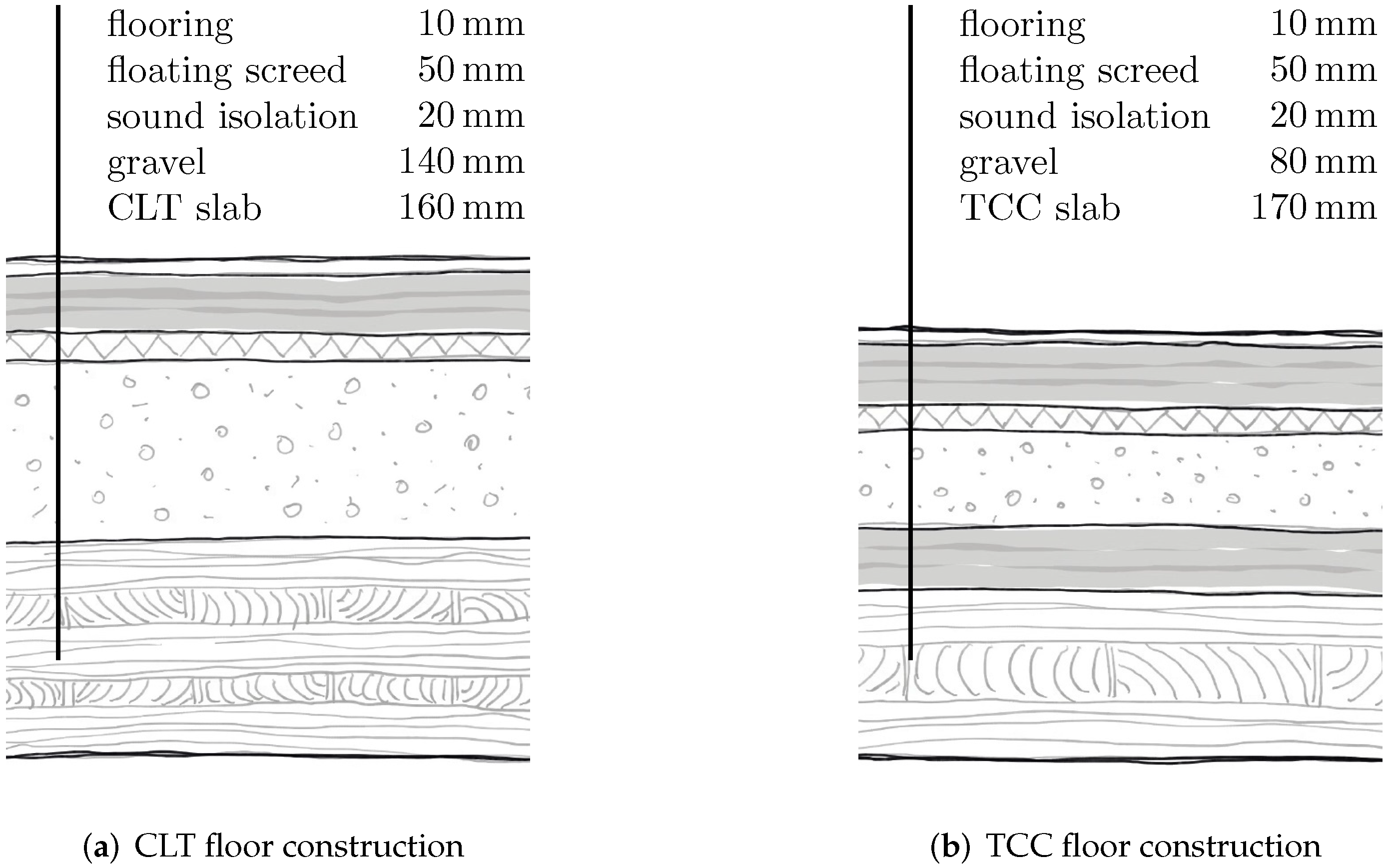
2.1. Investigated Slab Types

The reference CLT floor construction is taken from a residential building in Växjö Sweden, where the slab elements span over = 5.00 m. The load-carrying part is a 160 mm thick CLT panel with five layers (40-20-40-20-40 mm). According to the Swedish CLT handbook [2] it is necessary to put a 140 mm thick gravel layer on the CLT slab to fulfill the highest impact sound criterion in a residential building. This layer is usually followed by an impact sound insulation with a thickness of 20 mm, a floating screed with a thickness of 50 mm, and 10 mm thick flooring; see Figure 1a. The alternative TCC floor construction consists of a 120 mm thick CLT plate with three layers (40-40-40 mm) and a 50 mm thick concrete layer, which are connected with glued-in rebars with a diameter of 20 mm and a spacing of 200 mm in both directions. The floor construction on top of the load carrying TCC structure consists of an 80 mm thick gravel layer to obtain an equal self weight as the reference slab, and the same impact sound insulation, floating screed, and flooring as the reference floor construction; see Figure 1b.
As the behavior during the service life is of interest in this study, the characteristic loads and quasi-permanent load combinations need to be considered in the design for the serviceability limit state (SLS) according to EC 0 [37]. The characteristic live load of 1.50 kN/m2 in residential buildings (according to EC 1 [38]) is multiplied by the combination factor ψ 2 = 0.3 for the quasi-permanent load combination (according to EC 0 [37]). The quasi-permanent dead loads are equal to the characteristic values. The resulting characteristic loads for the short-term design and the quasi-permanent loads for the long-term design of the slabs are listed in Table 1 together with the corresponding layers of the floor structure. The static system for both slab types is a one-way spanning slab over 5.00 m between two wall elements. The wall supports are idealized as hinged line supports, and the slabs are not continuous.
In the following, the serviceability limit state design according to EC 5 [1] of both slab types is discussed. The 8 Hz criterion for residential floors is not fulfilled by the investigated slabs, which requires additional investigations regarding impact sound isolation. As this work focuses on the creep behavior during the service life, the impact sound behavior is assumed to be fulfilled by the type of chosen floor constructions on top of the load-carrying slab element and the mass of the total construction; see Table 1. Herein, the focus lies on the midfloor deflection over time. The maximum initial deflection of beams (or floor slabs) with characteristic loads should be within / 300 to / 500 , where is their span length. The maximum final deflection after 50 years with quasi-permanent loads should be limited by / 250 to / 350 according to the suggestions provided by EC 5. For the engineering design herein, the upper limits of the values according to EC 5 are considered, and the design values of the deflections at the two required time instances, namely, the initial deflection and the final deflection, are calculated. The considered stiffness values for concrete are based on EC 2 [27], assuming the load application at the 28th day. The timber stiffness is determined according to EN 338 [39]. The calculated deflections of both slab types in both design states are below or equal to the limits; see Table 2 for the numerical results and the corresponding stiffness values of the materials. The long-term deflections are the leading design criterion for both investigated slab types.

2.2. Time-Dependent Material Models

As the slabs are inside a building, the wooden parts are in service class 1 according to EC 5, with a small fluctuation in the moisture content (MC) over the CLT cross section. Hence, it is assumed that the long-term deformations of the timber parts are mainly governed by creep, and the influence of the MC change and possible mechano-sorptive effects are neglected. For the time-dependent behavior of the concrete parts, the hydration needs to be considered in addition to the creep. In the following, the two rheological models for the creep of both materials are expressed in a general way. As for both models, the Boltzmann superposition integral [40] needs to be solved; the analytical solution according to Ausweger et al. [41], based on a bi-linear loading path, is considered. The power law model, which is equivalent to a linear spring and a dashpot in series, for modeling the time-dependent stiffness S ( t ) after the load is applied ( t t 2 ) can be expressed as,
S ( t ) = 1 S e l + t r e f S v i ( t 2 t 1 ) ( α + 1 ) t t 1 t r e f α + 1 t t 2 t r e f α + 1 1 ,
where S e l and S v i represent the elastic and viscous parts of the modeled stiffness, t r e f is the reference time for the viscous stiffness, and α is the power law creep coefficient. The viscous stiffness S v i correlates directly with the viscous strains at the reference time due to an instantaneous applied constant load. The fractional Zener model is an extension of the power law model, i.e., the spring dashpot combination in a parallel series with a spring with the stiffness S i n . The total stiffness for t t 2 can be expressed as
S ( t ) = S i n + 1 S e l + t r e f S v i ( t 2 t 1 ) ( α + 1 ) t t 1 t r e f α + 1 t t 2 t r e f α + 1 1 .
As for the time-dependent stiffness of timber, the model type and the corresponding parameters are taken from Eitelberger et al. [35], who identified modeling parameters based on a multi-scale model for wood. All stiffness values related to the grain direction, e.g., the stiffness in the longitudinal direction E L t and the shear stiffness values G L T t and G L R t , are represented by a fractional Zener model as in Equation (2), while stiffness values in the plane perpendicular to the grain, e.g., the stiffness values in the radial and the tangential directions E R t and E T t and the rolling shear stiffness G R T t are expressed by the power law model as in Equation (1). For modeling CLT with the γ -method, which is described in detail in the following subsection, only the rolling shear stiffness and the stiffness in the grain direction are relevant. For the current study, spruce with a mean density of 450 kg/m3 and a moisture content of 10% is considered based on the multiscale model presented in [35], which falls in the strength class C 27 according to EN 338 [39] and is of slightly higher quality, like the strength class C 24 commonly used in commercial CLT products. The corresponding modeling parameters are taken from Eitelberger et al. [35], changed to the required form fitting Equations (1) and (2) and summarized in Table 3.
For the time-dependent material stiffness of concrete, the hydration process needs to be considered together with the creep behavior, which is in general expressed by a power law, as in Equation (1). Therefore, the elastic and viscous stiffnesses and the power law coefficient are needed. Königssberger et al. [36] identified a power law coefficient of 0.25 for all cementitious materials, and the fib Model Code 2010 [33] provides an evolution law for the elastic stiffness during the hydration
E e l c ( t ) = E e l , 28 d c exp s 1 28 d t 0.5 ,
where s is a factor depending on the strength class of the cement. Ausweger et al. [41] developed a correlation between elastic and viscous stiffness at a concrete age of 28 days
E v i , 28 d c = 51.9 GPa E e l , 28 d c 51.5 GPa 2
and an expression for the viscous stiffness with ongoing hydration
E v i c ( t ) = E v i , 28 d c exp s v 1 28 d t 0.5 .
For this study, a concrete of the strength class C 20/25 made out of CEM II/A-S 42.5 N with an elastic stiffness E e l , 28 d c = 30.0 GPa at a concrete age of 28 days according to EC 2 [27] is considered for the structural analysis.

2.3. Structural Analysis of Composite Slabs

Even if the composite slabs are only one-way spanning and simply supported, the stiffness of the individual layers and the connection between the layers influence the distribution of the internal forces between the layers. The distribution of the internal forces between the individual layers can be accounted for by applying the γ -method developed by Möhler in 1965 [28]. Due to its simplicity, it is included in Annex B of EC 5 [1] to calculate mechanically jointed timber beams. This method was developed for composites with three layers and negligible shear deformations of the individual layers, a continuous connection between the layers and a sinusoidal bending moment distribution, which is close to a parabolic distribution. The eponymous reduction coefficient γ is calculated for the outer layers as
γ i = 1 1 + π 2 E i A i s i K i 2 for i ϵ { 1 , 3 }
and is equal to one for the middle layer, i.e., γ 2 = 1.0 . The reduction coefficient depends mainly on the ratio between the axial stiffness, E i A i , and the smeared connection stiffness between the middle layer and the outer layers. The smeared connection stiffness is calculated by dividing the slip modulus of one individual connection element K i with the spacing between the connection elements s i . Considering the γ -values from Equation (6), an effective bending stiffness ( E I ) e f for the composite beam can be calculated as
( E I ) e f = i = 1 3 E i I i + γ i E i A i | a i | 2 ,
where A i is the cross-sectional area of the layer and a i is the distance (eccentricity) from the layer to the neutral axis. According to Annex B of EC 5, ( E I ) e f can be used for calculating the deflection in the middle of the span length w of the composite beam, similar to a homogeneous beam carrying a constant load p, such as
w = 5 4 p 384 ( E I ) e f .
Furthermore, the effective bending stiffness is required to calculate normal and shear stresses in the individual layers of the composite cross section. The normal stress σ i due to a bending moment M ( x ) along the beam axis consists of stresses induced by the composite action and stresses induced by pure bending of the individual layer, and can be calculated as
σ i ( x , z i ) = γ i E i a i M ( x ) ( E I ) e f E i z i M ( x ) ( E I ) e f ,
where x is the coordinate along the axis of the beam, z i the vertical coordinate of each layer with its origin in the center of the layer and a positive direction upwards. The shear stresses τ i inside a composite cross section, due to a shear force V ( x ) , are calculated as
τ i ( x , z i ) = V ( x ) ( E I ) e f b i j = 1 i 1 γ j E j A j a j + γ i E i b i h i 2 z i h i / 2 + z i 2 a i .
The expression in square brackets in Equation (10) represents the area moment of inertia extended by the γ -factor and material stiffness of the individual layers.
For this study, the composite consists either of five CLT layers (CLT slab) or three CLT layers with a concrete layer on the top (TCC slab), which are, in both situations, more than the allowed three layers for the γ -method. However, according to the CLT handbooks [2,31], it is possible to apply the method if the cross layers with the grain perpendicular to the spanning direction of the slab are treated as connection elements. The smeared slip modulus depends on the rolling shear stiffness of the cross layer and can be calculated as
k i = K i s i = G R T , i t b i h i .
Based on the mentioned assumptions, it is possible to apply the γ -method to both investigated slab types involved in this study. For the connection between the concrete layer and CLT plate in the TCC slab, it is assumed that there are glued-in rebars with a diameter of d = 20 mm and a spacing of s = 200 mm. The resulting slip modulus between timber and concrete K i t c can be estimated by the technical specifications for EC 5 [42], considering the stiffness of the timber in longitudinal direction E L t . If the time-dependent behavior of timber is considered, the slip modulus is also changing over time
K i t c ( t ) = 0.10 E L t ( t ) d .
Considering the time-dependent material stiffnesses, the γ -method and the connection stiffnesses according to Equations (11) and (12) allow to investigate both slab types.

3. Results

The investigation is divided into three parts, starting with the results from the time-dependent material modeling, followed by the application of the material models to the structural analysis of the slab structures and, in the end, the leading stresses of the individual layers of the investigated cross sections.

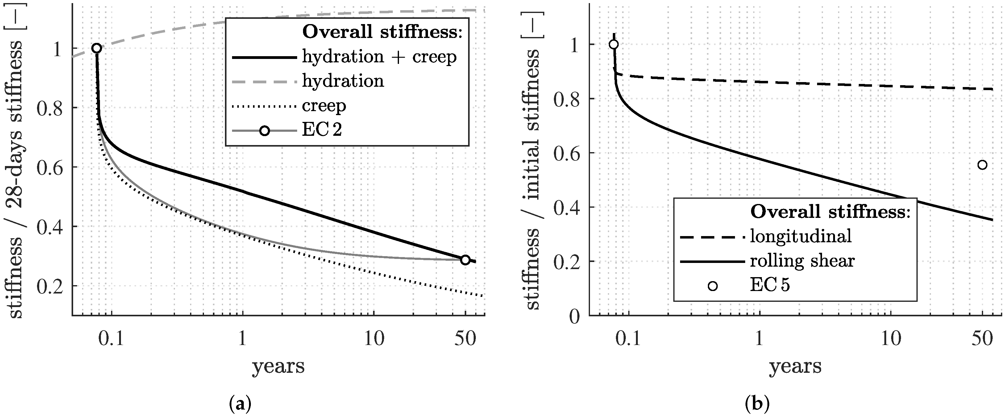
3.1. Time-Dependent Material Modeling

Modeling the overall material stiffness of concrete includes the time-dependent behavior due to hydration and creep. The stiffness increases during the hydration process are considered by evaluating Equations (3)–(5) for C 20/25 concrete and different hydration steps. The latter include 200 steps withing the first 10 days, 2 steps for every remaining day of the first year, 100 steps within the second to the tenth year, and 100 steps until 100 years are reached, which results in over 1000 considered time steps over the investigated service life. The hydration-dependent elastic and viscous stiffness values E e l c ( t ) and E v i c ( t ) are then used as input values for modeling the decreasing overall stiffness due to creep. Therefore, Equation (1) is first evaluated for loading at the 28th day after casting for all different hydration steps. Then, the overall stiffness E c ( t ) is summed up for every time step after loading, considering the different hydration steps.
Evaluating only the creep model without considering the ongoing hydration would result in much smaller stiffness values over the service life; see the model curves for the combined model (black solid line) and only the creep model (black dotted line) in Figure 2a. Furthermore, the increasing stiffness due to hydration is plotted in Figure 2a with a grey dashed line and shows the enormous influence of creep on the overall material stiffness. The standardized stiffness values are plotted with a grey solid line with markers at the loading and after 50 years.
Modeling the overall stiffness of timber due to creep requires distinguishing between the material directions. As for this study, the behavior in the longitudinal and the rolling shear directions is of interest, and only these directions are evaluated for the same time steps as for concrete. The time-dependent stiffness in longitudinal direction E L t ( t ) is calculated according to Equation (2), and the evolution of the rolling shear stiffness G R T t ( t ) follows Equation (1) with the modeling parameters for both directions summarized in Table 3. Plotting the overall stiffness in reference to the initial stiffness without the influence of creep results in a main difference between the two directions. During 50 years, the longitudinal stiffness decreases by less than 20%, but the rolling shear stiffness decreases by more than 60% of the initial stiffness; see the solid and dashed lines in Figure 2b. In addition, also the material direction independent approach according to EC 5, with a k d e f for all directions equal to 0.80 is represented by a marker in Figure 2b.

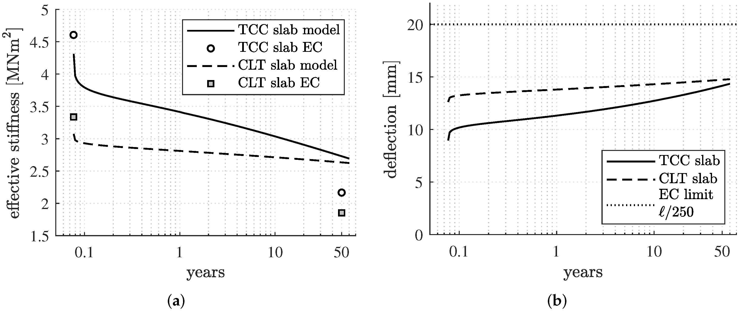
3.2. Time-Dependent Structural Analysis

Based on the modeled time-dependent material stiffness values of the individual layers, it is possible to calculate the evolution of the effective stiffness of the slabs according to the γ -method and the corresponding deflections. Therefore, Equations (6) and (7) are evaluated, and the midspan deflection is calculated according to Equation (8) for the different time steps during the lifetime of both slab types. The time-dependent stiffness values E L t ( t ) and E c ( t ) are considered for the stiffness of the individual layers. The time-dependent smeared slip modules required for the γ -values in Equation (6) are calculated for the CLT cross layers by inserting the time-dependent rolling shear stiffness G R T t ( t ) in Equation (11). For the connection between CLT and concrete, glued-in rebars with 20 mm diameter and 200 mm spacing are assumed, and the time-dependent stiffness E L t ( t ) is inserted in Equation (12) to obtain a slip modulus for every time step of the evaluation.
The change of the effective bending stiffness of the slabs shows that, directly after the load application, the TCC slab is about 35% stiffer than the CLT slab. During their service life, however, the difference between the effective stiffness values decreases to around 5%. Comparing the modeled evolution of the effective bending stiffness of both slabs at the beginning and at the end of the service life with the values according to the standards shows that the stiffness at the beginning is about 10% to 15% smaller, and after 50 years, it is about 40% higher than the standard. Figure 3a shows the modeled effective bending stiffness over the service life for the CLT slab with a black dashed line and for the TCC slab with a solid black line, and the standardized values are represented by markers. The corresponding midspan deflections of the slabs over time are calculated based on the effective stiffness values for both investigated slab types; see Figure 3b. As the deflection is in inverse proportion to the effective stiffness, at the beginning, the deflection of the TCC slab is about 25% smaller than the CLT slab deflection. After 50 years, however, the difference is reduced to approximately 7%. The / 250 -deflection limit is exceeded neither by the CLT nor by the TCC slab.

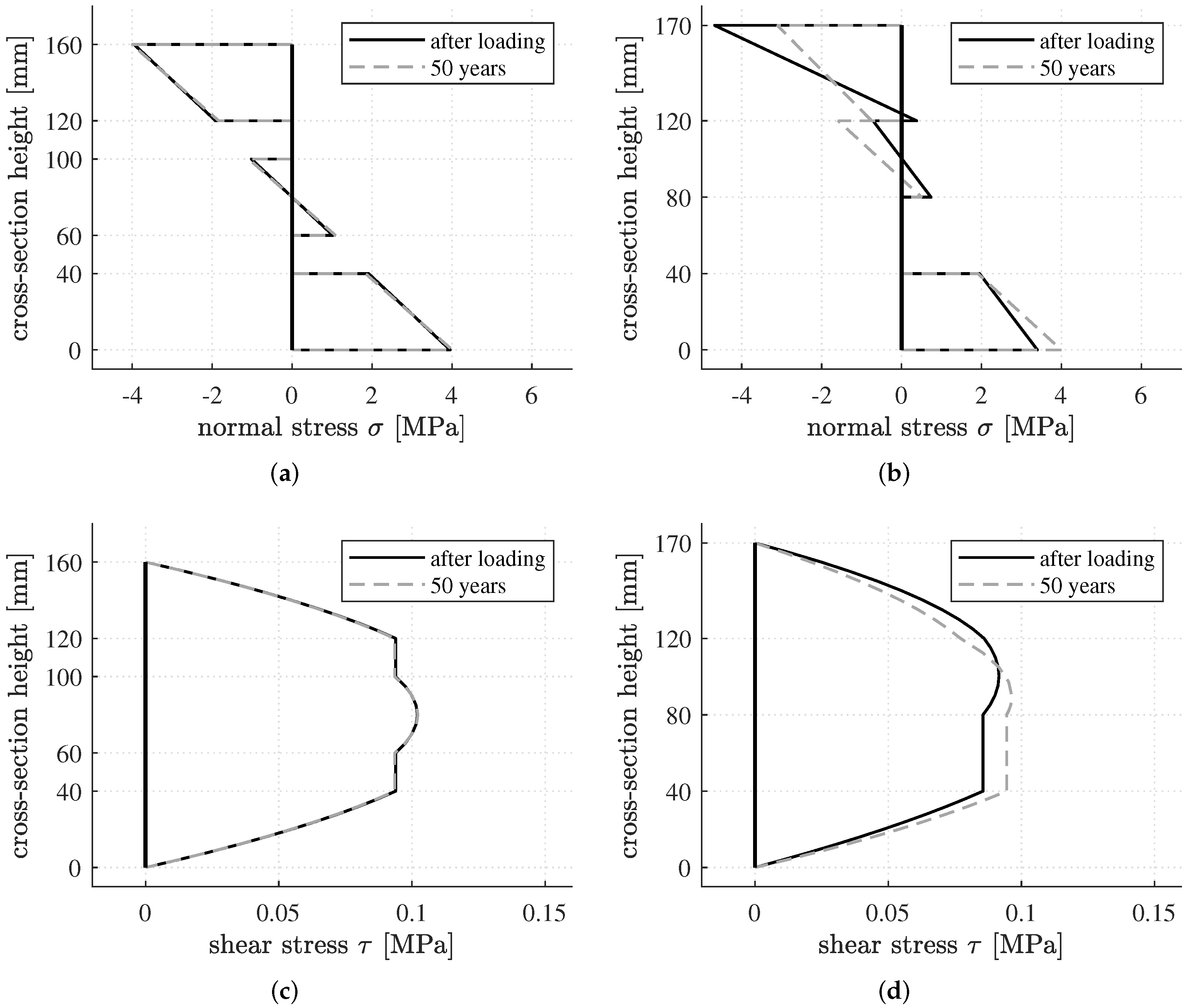
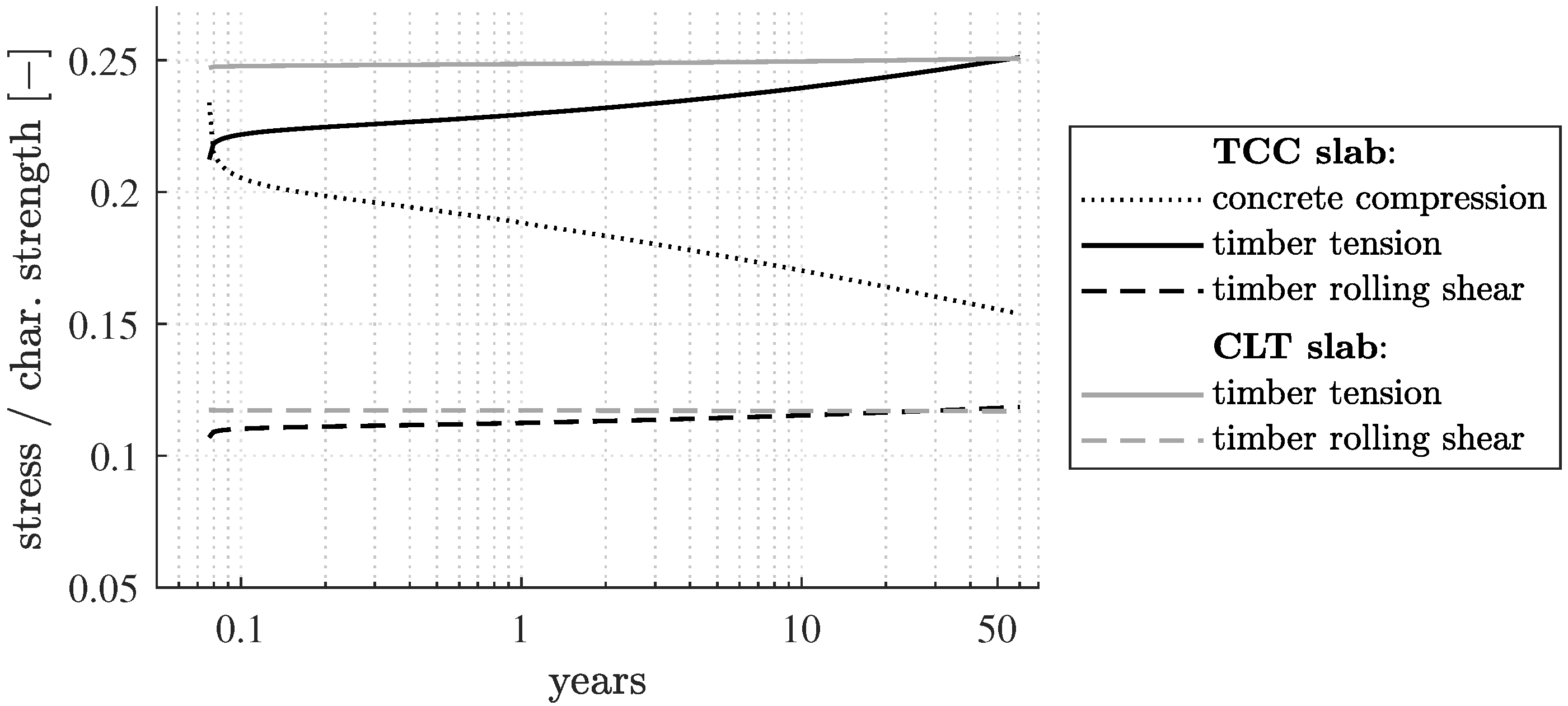
3.3. Time-Dependent Stress Distribution between the Layers

With the γ -method applied to different time steps during the service life, it is possible to calculate the shear and normal stresses of the individual layers in the composite cross section. Evaluating Equation (9) for the different layers of the CLT slab and the TCC slab by considering the respective time-dependent effective bending stiffness allows to calculate the normal stresses for each layer along the beam axis. As the maximum bending moment appears in the middle of the span length, the normal stress distribution along this cross section is exemplary evaluated after the load application and after 50 years for both investigated slab types. The distributions are plotted in Figure 4a for the CLT slab and in Figure 4b for the TCC slab. The normal stresses in the CLT slab are only minimally changing during the service life. For the TCC slab, however, the changes are distinct. The stress peaks are reduced for the concrete layers, but increase in the CLT layers over time.
For calculating the shear stresses over time, Equation (10) is evaluated along the beam axis, considering the time-dependent effective bending stiffness. Exemplarily, the shear stress distribution resulting from the maximum shear force at the supports is evaluated after the load application and after 50 years for both investigated slab types; see Figure 4c for the CLT slab and in Figure 4d for the TCC slab. The evolution of the shear stress over time is similar to the normal stress, namely there are minimal changes in the CLT slab, and there are more pronounced changes in the TCC slab.
Since the applied time-dependent material behavior is only valid for modeling linear elastic creep, it is checked if the individual stresses in the layers are below the 30% criterion regarding the utilization of the strength of timber [43,44] and the 45% criterion of concrete [27], which are considered limit stresses for linear elastic creep. The stress values in the individual layers are normalized by the corresponding strength values. Due to the variation of the material strength properties of concrete and timber, the characteristic strength values of C 27 timber and of C 20/25 concrete are considered for the linear creep criterion. In Figure 5, the ratio between the leading stresses for the design, which can be either positive or negative, and the respective characteristic strength are plotted. The material utilization stays below 25% during the investigated service life time. Hence, the applied time-dependent material models are valid.
The evolution of the normalized stresses of the TCC slab, presented in Figure 5, shows that the compressive stress in the concrete layer decreases, while the normal stress in the longitudinal layers and the rolling shear stress in the CLT cross layer increase. Because concrete is a more creep-active material than timber in the longitudinal direction (see Figure 2), the unchanging total load is redistributed between the layers of a TCC cross section over time. The normal stresses due to bending of the individual layers decrease for the concrete layer and increase in the deck layers of the CLT slab. However, the mean stresses of the outer layers change less due to the load redistribution; see the stress distribution along the cross section at the beginning and at the end of the service life in Figure 4b.
The load redistribution in the CLT slab is negligible. However, a closer look at the results of the modeling shows that shortly after the load application, the rolling shear stress in the cross-layers is reduced and the normal stress in the longitudinal layers is increasing; see Figure 5. The redistribution is induced by the more creep-active cross layers that withdraw more from the loading than the timber layers loaded in the grain direction. As the load is mainly carried by the longitudinal layers, the influence of the load redistribution is hardly noticeable.

4. Discussion

The main objective of the presented work is to model the long-term deflection of composite slabs, either CLT or TCC, made of a concrete layer on top of a CLT slab. The presented hybrid approach requires the following discussion.
Regarding the considered and extended material models, in the timber research, recent experiments show that the creep behavior of wood depends on the material direction, e.g., [45,46,47], which would be disregarded following the design rules of EC 5 [1]. By considering the multiscale-based proposed rheological models from Eitelberger et al. [35], the different creep behavior of the individual layers in the CLT is incorporated. According to EC 2, the decrease in the stiffness due to creep and the stiffness increase due to hydration are handled independently. The applied multiscale-based creep model [36] and the evolution of the viscous properties [41] are compatible, as the research on the latter is based on the assumptions of the multiscale model.
The multiscale-based models for timber [35] and concrete [36] are only considering visco-elastic deformations due to loading in a constant climate, which is not the case inside a residential building. Within this research, it is assumed that climate changes inside a residential building (service class 1) represent no dominant influence on the mean long-term deflection of installed and covered floor elements, because of small changes of the moisture content of the timber. This assumption is in agreement with experiments [12]. The modeling does not account for mechano-sorptive effects, which have a leading role in the deformation during the first two years of loading in an outside climate, e.g., [6,7,25] and need to be considered for other climate situations. As for modeling concrete, two main time-dependent processes, namely hydration and creep, are considered, but shrinkage is not considered in this research, neither for concrete nor for timber.
Regarding the structural analysis, the applied γ -method is a standardized solution for simply supported beams with a composite cross section made of a maximum of three layers. The method allows to calculate deflections based on an effective bending stiffness and the stress distribution between the layers of the composite, which covered the main interest of the presented work. The time-dependent multiscale model-based material stiffness values serve as input for the γ -method, and a time-dependent structural behavior of the slabs could be modeled. However, since the cross layers of the CLT plates need to be treated as connecting elements and not independent layers, to be able to apply the γ -method, the resulting stresses in these layers need to be seen as approximations. For extending the presented hybrid modeling approach to more layers, e.g., TCC slabs constructed by a CLT with more than three layers, it is necessary to extend the method (see, for example, [29]), or use other methods, such as the shear analogy method [48] or FE modeling, for the structural analysis.
Nevertheless, the modeling results based on this simplified approach allow to model the evolution of the deflection over time of the two slab types, see Figure 3b. The CLT slab has a higher initial deflection than the TCC slab, but due to the influence of creep during the service life and a stronger creep of the TCC slab, the differences reduce over time. After 50 years service life, the deflections of the two investigated slab types are rather similar. Since neither for the CLT slab nor for the TCC slab comparable experimental investigations exist, validation of this hybrid modeling approach is not possible. Experimental investigations of TCC slabs in the literature focused on T-shaped beam elements, e.g., [6,7,29,49], or slabs made of other wood products, e.g., [8,30]. Long-term experiments on CLT slabs are rare in the literature. The situation is similar for long-term model predictions of the two investigated slab types. To the authors’ knowledge, there are no documented modeling attempts involving the creep deformations of CLT elements.
Regarding the load redistribution between the composite layers over the service life, due to the different creep behavior of the involved layers of both slab types, the load is redistributed. Changes in the stresses of the layers are shown in Figure 5. The load redistribution in the CLT slab is negligible due to the creep inactivity of timber in the longitudinal material direction and the large initial stiffness difference of the layers, which is, in addition, not fully accounted for by the chosen simplified structural analysis method. However, the load redistribution in the TCC element is much more pronounced in comparison with the CLT slab. The creep active concrete layer takes over a lot of load in the beginning, which is then withdrawn over time, which leads to a load redistribution. Hence, the compressive stress in the concrete decreases, and the normal stress and rolling shear stress in the CLT part increase over the time; see Figure 5. These stress changes in the individual layers happen slowly during the service life and are unaccounted for by the Boltzmann superposition principle [40]. As the changes of the mean stresses of each layer are small over time, it is assumed that this influence on the results is negligible.

5. Conclusions

The comparison of the CLT slab and the TCC slab, consisting of a CLT plate and a concrete layer on top, was conducted by a hybrid approach, including time-dependent material models for the individual layers. Based on the modeled creep behavior of the two composite slabs during service life, the following can be concluded:
  • The hybrid approach considers individual time-dependent material models for the involved materials, i.e., for timber in the longitudinal direction, for timber in rolling shear direction, and for hydrating concrete. Midspan deflections of the slabs due to creep over the service life were modeled, and the load redistribution between the layers of the hybrid cross sections was investigated. Even if the cross-layers of the CLT were considered only for connecting the longitudinal layers and not for carrying normal stresses, a load redistribution from the cross layers toward the longitudinal layers due to different creep behavior of the layers was found. Due to the creep behavior, together with the ongoing hydration of the concrete layer, a significant amount of normal stresses redistribute from the concrete layer to the CLT plate during the service life.
  • The comparison of the long-term deflections of the slabs shows that the CLT slab is less stiff in the beginning, but the overall stiffness reduction is smaller than for the TCC slab. After 50 years of use, the midspan deflections of both investigated slab types were quite similar. As both slab types should provide the same level of impact sound protection between floors of residential buildings, the TCC slab with a 50 mm reduced construction height would be preferred if the total construction height of a multistory building is limited.
  • The introduced hybrid approach is simple, but nonetheless allows to consider advanced material models for the individual layers of the composite structure without additional software. For the future, it is desirable to validate the hybrid approach with experiments. As for future improvements of the hybrid approach, the method for the structural analysis should consider shear and normal stresses in all layers. This will allow to investigate the load redistribution between the layers in more detail.
Modeling not only the creep behavior, but also the influence of climate changes and mechano-sorptive effects on the long-term behavior of the slabs is needed if composite structures are to be installed in changing environmental conditions, e.g., outside for balconies or bridges. Worth mentioning in this context is that CLT plates are not approved for such environmental conditions yet. As the mechanical properties of timber are much more influenced by moisture changes than the properties of concrete, it would be interesting to investigate the load redistribution within the composite cross section over seasonal changes with an improved hybrid approach in the future.

Author Contributions

Conceptualization of the study, E.B., W.D. and T.K.B.; developing, software implementation, and analysis of the presented approach, E.B.; interpretation of the results, E.B., W.D. and T.K.B.; preparation of the original draft, E.B.; review and editing of the manuscript; E.B., W.D. and T.K.B.; supervision, W.D. and T.K.B. All authors have read and agreed to the published version of the manuscript.

Funding

This research received no external funding.

Institutional Review Board Statement

Not applicable.

Informed Consent Statement

Not applicable.

Data Availability Statement

The data presented in this study are available on request from the corresponding author.

Acknowledgments

The discussions with Michael Schweigler, Carmen Amaddeo, and Carl Larsson are gratefully acknowledged.

Conflicts of Interest

The authors declare no conflict of interest.

References

  1. European Committee for Standardization. EN1995-1-1:2004 Eurocode 5: Design of Timber Structures—Part 1-1: General—Common Rules and Rules for Buildings; Swedish Standards Institute (SIS): Stockholm, Sweden, 2004. [Google Scholar]
  2. Borgström, E.; Fröbel, J. (Eds.) The CLT Handbook; Svenskt Trä—Swedish Wood: Stockholm, Sweden, 2019. [Google Scholar]
  3. Derkowski, W. Large panels buildings-the possibilities of modern precast industry. Cem. Wapno Beton 2017, 22, 414–425. [Google Scholar]
  4. Derkowski, W. New solutions for prefabricated floor slabs. Cem. Wapno Beton 2019, 24, 372–382. [Google Scholar]
  5. Neve, O.; Spencer-Allen, L. Shaking up dance floor design with timber–concrete composites. Proc. Inst. Civ. Eng. Constr. Mater. 2015, 168, 204–212. [Google Scholar] [CrossRef]
  6. Blaß, H.J.; Romani, M. Langzeitverhalten von Holz-Beton-Konstruktionen; Fraunhofer-IRB-Verlag: Stuttgart, Germany, 2002. [Google Scholar]
  7. Ceccotti, A.; Fragiacomo, M.; Giordano, S. Long-term and collapse tests on a timber-concrete composite beam with glued-in connection. Mater. Struct. 2007, 40, 15–25. [Google Scholar] [CrossRef]
  8. Fragiacomo, M.; Gutkowski, R.; Balogh, J.; Fast, R. Long-term behavior of wood-concrete composite floor/deck systems with shear key connection detail. J. Struct. Eng. 2007, 133, 1307–1315. [Google Scholar] [CrossRef]
  9. To, L.; Fragiacomo, M.; Balogh, J.; Gutkowski, R.M. Long-term load test of a wood–concrete composite beam. Proc. Inst. Civ. Eng. Struct. Build. 2011, 164, 155–163. [Google Scholar] [CrossRef]
  10. Yeoh, D.; Fragiacomo, M.; Deam, B. Long-term performance of LVL-concrete composite beams under service load. In Proceedings of the WCTE—World Conference on Timber Engineering, Auckland, New Zealand, 15–19 July 2012; Volume 3, p. 3. [Google Scholar]
  11. Fragiacomo, M.; Lukaszewska, E. Time-dependent behaviour of timber–concrete composite floors with prefabricated concrete slabs. Eng. Struct. 2013, 52, 687–696. [Google Scholar] [CrossRef]
  12. Augeard, E.; Ferrier, E.; Michel, L. Mechanical behavior of timber-concrete composite members under cyclic loading and creep. Eng. Struct. 2020, 210, 110289. [Google Scholar] [CrossRef]
  13. Takanashi, R.; Ohashi, Y.; Ishihara, W.; Matsumoto, K. Long-term bending properties of cross-laminated timber made from Japanese larch under constant environment. J. Wood Sci. 2021, 67, 65. [Google Scholar] [CrossRef]
  14. Jöbstl, R.A.; Schickhofer, G. Comparative Examination of Creep of GLT and CLT Slabs in Bending. In Proceedings of the Working Commission CIB W18—Timber Structures, Bled, Slovenia, 28–31 August 2007; Volume 40, pp. 1–15. [Google Scholar]
  15. Schänzlin, J. Zum Langzeitverhalten von Brettstapel-Beton-Verbunddecken (About the Long Term Behaviour of Composite Floors of Board Stacks and Concrete). Ph.D. Thesis, University of Stuttgart, Stuttgart, Germany, 2003. [Google Scholar]
  16. Rüsch, H.; Jungwirth, D. Stahlbeton-Spannbeton: Berücksichtigung der Einflüsse von Kriechen und Schwinden auf das Verhalten der Tragwerke: Hubert Rüsch; Werner: Los Angeles, CA, USA, 1976; Volume 2. [Google Scholar]
  17. Kupfer, H.; Kirmair, H. Verformungsmoduln zur Berechnung statisch unbestimmter Systeme aus zwei Komponenten mit unterschiedlichen Kriechzahlen. Der Bauing. 1987, 62, 371–377. [Google Scholar]
  18. Fragiacomo, M.; Ceccotti, A. Long-term behavior of timber–concrete composite beams. I: Finite element modeling and validation. J. Struct. Eng. 2006, 132, 13–22. [Google Scholar] [CrossRef]
  19. Fragiacomo, M. Long-term behavior of timber–concrete composite beams. II: Numerical analysis and simplified evaluation. J. Struct. Eng. 2006, 132, 23–33. [Google Scholar] [CrossRef]
  20. Fragiacomo, M. Experimental behaviour of a full-scale timber-concrete composite floor with mechanical connectors. Mater. Struct. 2012, 45, 1717–1735. [Google Scholar] [CrossRef]
  21. Khorsandnia, N. Finite Element Analysis for Predicting the Short-Term and Longtermbehaviour of Timber-Concrete Composite Structures. Ph.D. Thesis, University of Technology, Sydney, Ultimo, Australia, 2013. [Google Scholar]
  22. Khorsandnia, N.; Valipour, H.; Foster, S.; Crews, K. A force-based frame finite element formulation for analysis of two- and three-layered composite beams with material non-linearity. Int. J. Non-Linear Mech. 2014, 62, 12–22. [Google Scholar] [CrossRef]
  23. Khorsandnia, N.; Schänzlin, J.; Valipour, H.; Crews, K. Time-dependent behaviour of timber–concrete composite members: Numerical verification, sensitivity and influence of material properties. Constr. Build. Mater. 2014, 66, 192–208. [Google Scholar] [CrossRef]
  24. Khorsandnia, N.; Schänzlin, J.; Valipour, H.; Crews, K. Coupled finite element-finite difference formulation for long-term analysis of timber–concrete composite structures. Eng. Struct. 2015, 96, 139–152. [Google Scholar] [CrossRef]
  25. Schänzlin, J.; Fragiacomo, M. Analytical derivation of the effective creep coefficients for timber-concrete composite structures. Eng. Struct. 2018, 172, 432–439. [Google Scholar] [CrossRef]
  26. Nie, Y.; Valipour, H. Experimental and numerical study of long-term behaviour of timber-timber composite (TTC) connections. Constr. Build. Mater. 2021, 304, 124672. [Google Scholar] [CrossRef]
  27. European Committee for Standardization. EN1992-1-1:2011 Eurocode 2: Design of Concrete Structures—Part 1-1: General Rules and Rules for Buildings; Swedish Standards Institute (SIS): Stockholm, Sweden, 2011. [Google Scholar]
  28. Möhler, K. Über das Tragverhalten von Biegeträgern und Druckstäben mit zusammengesetzten Querschnitten und Nachgiebigen Verbindungsmitteln; Habilitation; Technical University of Karlsruhe: Karlsruhe, Germany, 1956. (In German) [Google Scholar]
  29. Jiang, Y.; Crocetti, R. CLT-concrete composite floors with notched shear connectors. Constr. Build. Mater. 2019, 195, 127–139. [Google Scholar] [CrossRef]
  30. Jorge, L.; Schänzlin, J.; Lopes, S.; Cruz, H.; Kuhlmann, U. Time-dependent behaviour of timber lightweight concrete composite floors. Eng. Struct. 2010, 32, 3966–3973. [Google Scholar] [CrossRef]
  31. Wallner-Novak, M.; Koppelhuber, J.; Pock, K. Cross-Laminated Timber Structural Design—Basic Design and Engineering Principles according to Eurocode; proHolz: Innsbruck, Austria, 2014. [Google Scholar]
  32. Fink, G.; Kohler, J.; Brandner, R. Application of European design principles to cross laminated timber. Eng. Struct. 2018, 171, 934–943. [Google Scholar] [CrossRef]
  33. International Federation for Structural Concrete (fib—fédération internationale du béton). fib Model Code for Concrete Structures 2010; Ernst & Sohn: Hoboken, NJ, USA, 2013. [Google Scholar]
  34. Toratti, T. Creep of Timber Beams in Variable Environment. Ph.D. Thesis, Helsinki University of Technology, Espoo, Finland, 1992. [Google Scholar]
  35. Eitelberger, J.; Bader, T.; de Borst, K.; Jäger, A. Multiscale prediction of viscoelastic properties of softwood under constant climatic conditions. Comput. Mater. Sci. 2012, 55, 303–312. [Google Scholar] [CrossRef]
  36. Königsberger, M.; Irfan-ul Hassan, M.; Pichler, B.; Hellmich, C. Downscaling Based Identification of Nonaging Power-Law Creep of Cement Hydrates. J. Eng. Mech. 2016, 142, 04016106. [Google Scholar] [CrossRef]
  37. European Committee for Standardization. EN1990:2010 Eurocode—Basis of Structural Design; Swedish Standards Institute (SIS): Stockholm, Sweden, 2010. [Google Scholar]
  38. European Committee for Standardization. EN1991-1-1:2010 Eurocode 1: Actions on Structures—Part 1-1: General Actions—Densities, Self-Weight, Imposed Loads for Buildings; Swedish Standards Institute (SIS): Stockholm, Sweden, 2010. [Google Scholar]
  39. European Committee for Standardization. EN 338:2016 Structural Timber—Strength Classes; Swedish Standards Institute (SIS): Stockholm, Sweden, 2016. [Google Scholar]
  40. Boltzmann, L. Zur Theorie der elastischen Nachwirkung [On the theory of creep recovery]. Ann. Der Phys. 1878, 241, 430–432. [Google Scholar] [CrossRef]
  41. Ausweger, M.; Binder, E.; Lahayne, O.; Reihsner, R.; Maier, G.; Peyerl, M.; Pichler, B. Early-Age Evolution of Strength, Stiffness, and Non-Aging Creep of Concretes: Experimental Characterization and Correlation Analysis. Materials 2019, 12, 207. [Google Scholar] [CrossRef] [PubMed] [Green Version]
  42. European Committee for Standardization. CEN/TS 19103 Technical Specification for Eurocode 5: Design of Timber Structures—Structural Design of Timber-Concrete Composite Structures—Common Rules and Rules for Buildings; Austrian Standards International: Vienna, Austria, 2021. [Google Scholar]
  43. Massaro, F.M.; Malo, K.A. Long-term behaviour of norway spruce glulam loaded perpendicular to grain. Eur. J. Wood Wood Prod. 2019, 77, 821–832. [Google Scholar] [CrossRef]
  44. Schniewind, A.P. Recent progress in the study of the rheology of wood. Wood Sci. Technol. 1968, 2, 188–206. [Google Scholar]
  45. Tong, D.; Brown, S.A.; Corr, D.; Cusatis, G. Wood creep data collection and unbiased parameter identification of compliance functions. Holzforschung 2020, 74, 1011–1020. [Google Scholar] [CrossRef]
  46. Allemand, C.; Lebée, A.; Manthey, M.; Forêt, G. Characterization of rolling ang longitudinal shear creeps for cross laminated timber panels. In Proceedings of the 8th International Network on Timber Engineering Research (INTER) Meeting, Karlsruhe, Germany, 16–19 August 2021. (online meeting). [Google Scholar]
  47. Akter, S.T.; Binder, E.; Bader, T.K. Moisture and short-term time-dependent behavior of Norway spruce clearwood under compression perpendicular to the grain and rolling shear. Wood Mater. Sci. Eng. 2022. submitted for publication. [Google Scholar]
  48. Scholz, A. Ein Beitrag zur Berechnung von Flächentragwerken aus Holz. Ph.D. Thesis, Technische Universität München, Munich, Germany, 2004. [Google Scholar]
  49. Shi, B.; Liu, W.; Yang, H. Experimental investigation on the long-term behaviour of prefabricated timber-concrete composite beams with steel plate connections. Constr. Build. Mater. 2021, 266, 120892. [Google Scholar] [CrossRef]
Figure 1. Investigated residential floor constructions: identical 10 mm flooring, 50 mm floating screed, and 20 mm sound insulation (a) on a CLT slab (160 mm) with a 140 mm thick layer of gravel, resulting in an overall thickness of the floor structure of 380 mm and (b) on a TCC slab (170 mm) with an 80 mm thick layer of gravel and a total thickness of 330 mm.
Buildings 12 00239 g001
Figure 2. Time-dependent overall material stiffness values for (a) concrete in reference to the stiffness according to EC 2 after 28 days following the hydration model and creep model of [33,41] and for (b) timber normalized by the initial stiffness without the influence of creep following the rheological models based on the multiscale creep model of [35].
Buildings 12 00239 g002
Figure 3. Time-dependent changes during the service life of both slab types: (a) effective bending stiffness of the composite cross section and (b) deflection in the middle of the span.
Buildings 12 00239 g003
Figure 4. Stress distribution along one cross section at the beginning and after 50 years of service life of both slab types: (a,c) normal and shear stresses of CLT slab (b,d) normal and shear stresses of TCC slab. Results are based on the assumption that the CLT middle-layer are connection elements only.
Buildings 12 00239 g004
Figure 5. Normalized leading stresses in timber and concrete layer of both slab types: normalization is referring to the characteristic strength values from EC 2 for concrete C 20/25 and EN 338 for timber C 27.
Buildings 12 00239 g005
Table 1. SLS design loads per square meter for the two investigated floor constructions considering the the following mass densities: CLT—450 kg/m3, concrete—2400 kg/m3, gravel—1700 kg/m3, sound isolation—140 kg/m3, screed—2000 kg/m3, flooring—2000 kg/m3.
Load TypeDesign Situation/
Layer
CLT Slab
Thickness [mm]
Load
[kN/m2]
TCC Slab
Thickness [mm]
Load
[kN/m2]
live loadcharacteristic-1.50-1.50
quasi-permanent-0.45-0.45
self weightflooring100.20100.20
floating screed501.00501.00
sound insulation200.03200.03
gravel1402.38801.36
concrete layer--501.20
CLT1600.711200.53
3804.323304.32
SLS loadscharacteristic 5.82 5.82
quasi-permanent 4.77 4.77
Table 2. SLS deflection design for the two investigated slab types: considering material parameters from EC 2 for C 20/25 and EN 338 for C 27; utilization factors for the deflection in percentage are given in brackets next to the deflection value.
Time IncidentStiffness ValuesCLT Slab
Deflection
TCC Slab
Deflection
EC 5
Limit
28 days
(loading time)
E L , e l t ( 28 ) = 11.5  GPa14 mm (82%)10 mm (59%)17 mm ( / 300 )
G R T t ( 28 ) = 72.0  MPa
E e l c ( 28 ) = 30.0  GPa
50 years E L , e l t ( 50 ) = 6.2  GPa20 mm (100%)17 mm (85%)20 mm ( / 250 )
G R T t ( 50 ) = 39.0  MPa
E e l c ( 50 ) = 8.6  GPa
Table 3. Modeling parameters for the CLT elements of both slab constructions: parameters for spruce with a density of 450 kg/m3 and a moisture content of 10% defined for a reference time t r e f = 1.0 s in [35].
Material DirectionRheological ModelParameters
longitudinalfractional Zener E L , i n t = 10.527  GPa E L , e l t = 1.639  GPa
E L , v i t = 59.880  GPa α L t = 0.2121
rolling shearpower-law G R T , e l t = 77.7  MPa G R T , v i t = 3116  MPa
α R T t = 0.2067
Publisher’s Note: MDPI stays neutral with regard to jurisdictional claims in published maps and institutional affiliations.

