Article

A Modified Compression Field Theory Based Analytical Model of RC Slab-Column Joint without Punching Shear Reinforcement

1
School of Civil Engineering and Architecture, Zhejiang Sci-Tech University, Hangzhou 310018, China
2
Earthquake Engineering Research & Test Centre, Guangzhou University, Guangzhou 510006, China
*
Author to whom correspondence should be addressed.
Buildings 2022, 12(2), 226; https://doi.org/10.3390/buildings12020226
Submission received: 18 January 2022 / Revised: 6 February 2022 / Accepted: 15 February 2022 / Published: 17 February 2022
(This article belongs to the Special Issue Uncertainty Propagation of Complex Engineering Structures/Systems)

Abstract

:
RC slab–column structures are widely used because of the advantages of small space occupation for horizontal members, easy construction and good economy. However, slab–column joints are prone to punching shear failures, which deteriorates structural safety. This paper provides an analytical model to predict the punching shear capacity of the RC slab–column joint. A database of 251 test results is established for the shear punching capacity of slab–column joints without punching shear reinforcement. The performance of existing design codes in predicting the shear resistance of slab–column joints is investigated and compared based on the database. Then, based on the modified compression field theory (MCFT) model, an equation for calculating the punching shear resistance of slab–column joints without punching shear reinforcement is established. The prediction results of the analytical model are enhanced by using the regression analysis method. The model proposed in this paper is based on both reliable theoretical and the summary of a large number of test results, which has higher prediction accuracy than the design codes.

1. Introduction

The RC slab–column structure has no beams between the columns, and thus, is a form transfer load directly from slabs to columns [1,2]. The slab–column structure also has the advantages of flexible layout, full use of height space, fast construction speed and low cost. It is widely used in warehouses, underground garages, bridges and ports [3,4]. However, the RC slab column structure may undergo punching shear at the slab column joints under bending and shear loads. With small slab–column deformation, sudden punching shear failure can occur which leads to serious problems [5,6,7,8]. Brittle punching shear failure of RC slabs is usually caused by high shear stresses around the slab–column joint [9]. Due to the mechanisms of brittle failure at slab–columns joints, it is easy to cause progressive collapse, which affects the integrity of the structures [10]. On 24 June 2021, a condominium building collapsed [11] in which 98 people were killed in the accident (Figure 1). Scholars have carried out a lot of research in the hope of improving the understanding of the punching shear [9,12,13]. However, the mechanism of punching shear of slab–column structures is complex; therefore, the punching shear problem is still open for investigation.
Many researchers started with theoretical approaches to find mechanical explanations for punching shear and predicted the punching shear resistance of slab–columns by using various theoretical models. Bazant and Cao [14] introduced the fracture mechanics model to study the punching shear process of slab–column and Hallgren [15] also used nonlinear fracture mechanics to study the effect of size effect on high-strength concrete. Yankelevsky et al. [16], Nielsen [17], Johansen [18], Silva [19], Cai and Lin [20], studied the punching shear of slab–column based on the theory of plasticity. Based on seismic mitigation strategies and cost-benefit criteria, the deformation and forces at slab–column joints need to be analyzed and quantified [21]. However, the above models give poor consideration to the deformation capacity of slab–columns [21]. Based on elastic thin-plate theory, Long [22] presented an analytical model for punching shear capacity and summarized the criteria for different failure types of slab–column joints. Kinnunen and Nylander [23] proposed a model to calculate the ultimate rotation of the slab to study the punching shear capacity of RC slabs. The object of study for this model is sector elements in the radial flexure cracks. This model considers that when the radial inclined compression stress and the tangential compression strain near the column reach critical values the punching occurs. Then, the size effect was taken into account and a solution for the ultimate rotation was derived by Broms [12,24] to make the model more accurate. According to nonlinear fracture mechanics, Hallgren [15] proposed a model that the height of the concrete compression zone was used to derive the effects of size effect for the punching capacity of high-strength RC slab–column joints. Based on the conclusion of Walraven [25], assuming that the width of a critical shear crack is proportional to the rotation of the slab, Ruiz and Muttoni [2] proposed critical shear crack theory (CSCT). The effects of crack width and aggregate interlocking on the punching resistance of the slab–column joints were considered in the model. The accuracy of the relationship between the rotation angle ( φ ) and the internal forces in CSCT was verified by experiments. Then, the aggregate was considered and CSCT was improved by Guandalini et al. [26]. The theoretical models mentioned above study the punching shear behavior of slab–columns from multiple perspectives. The prediction of punching shear becomes more accurate, but the models and equations are relatively complex.
In RC slabs without punching shear reinforcement, the brittle punching failure has a higher probability [6], and thus, the slab–column joints without punching shear reinforcement are the research subjects in this paper. As far as we are concerned the punching shear (within vertical load) of RC slab–column joints without punching shear reinforcement are similar to shear diagonal tension failure of RC beams with a large shear-to-span ratio, and this failure is caused by the direct stress and shear stresses in the concrete. Therefore, based on the Modified Compression Field Theory (MCFT), a punching shear equation is proposed by transforming the three-dimensional mechanics into two-dimensional plane mechanics. With detailed specimen parameters, the equation has a relatively simple form and can achieve relatively accurate prediction.
The purpose of this paper is to establish an analytical model for punching shear capacity of RC slab–column joint that is based on justified theoretical deduction and the experimental database. In Section 1, a database that includes 251 slab–column joints tests are established. The database collects and collates the specific parameters of the slab–column joints without punching shear reinforcement. In Section 2, a total of five design codes are selected in this paper. The performance of existing design codes in predicting the shear resistance of slab–column joints are investigated and compared with the experimental results from the database. In Section 3, the Modified Compression Field Theory (MCFT) is applied to give the mechanical basis of punching shear behavior in interior slab–column joints without punching shear reinforcement. An equation for the punching shear resistance of slab–column joints without punching shear reinforcement is established. In order to improve the proposed model, parameters in the model are determined by regression analysis. The proposed model is compared with the existing methods provided by other design codes, verifying the correctness and effectiveness of the model.

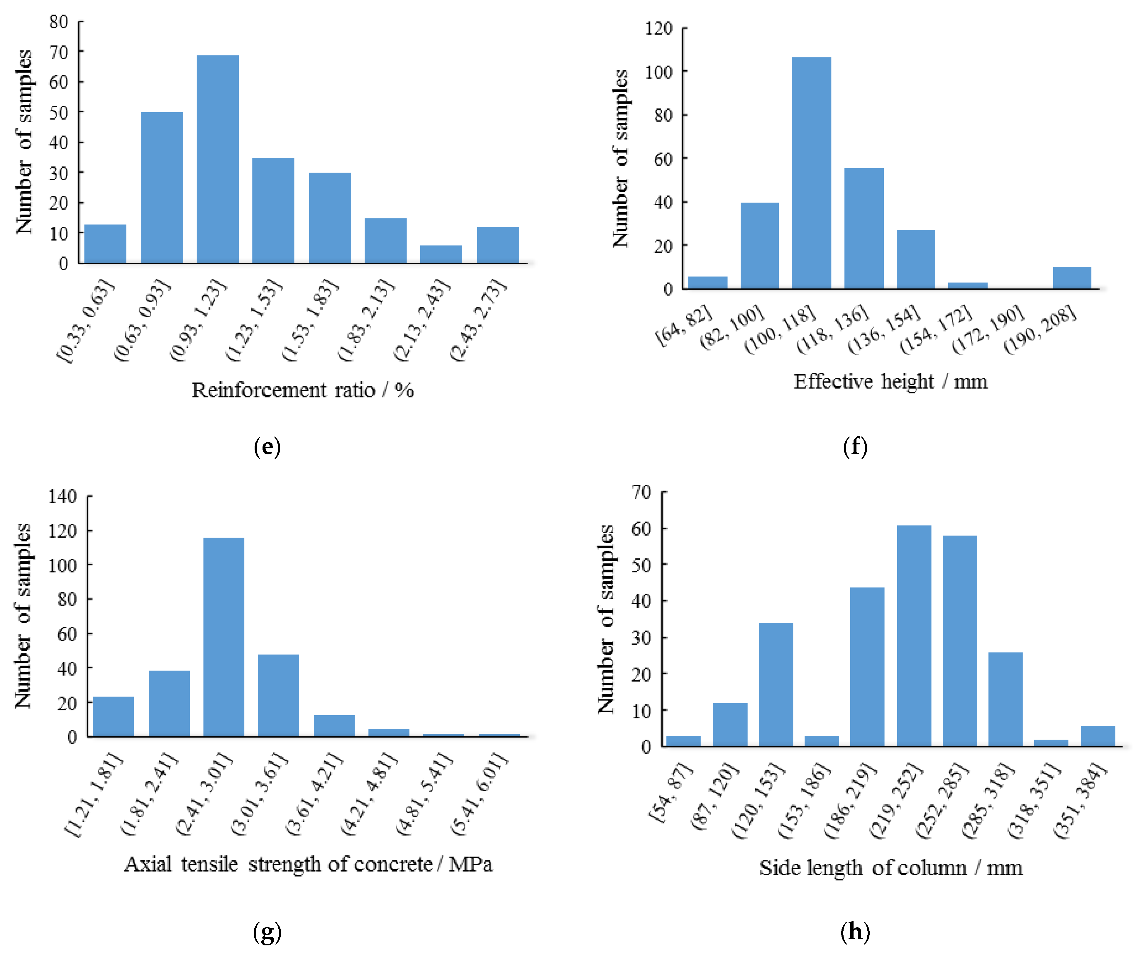
2. Experimental Database

According to a literature review, a database of 251 tests is established. The following criteria are used in collecting tests data: (1) The selected tests are RC slab–column joints (within vertical load), and the shape of the specimen is rectangular, which can exclude the influence caused by the shape; (2) The flexure reinforcement is arranged at the bottom of the slab, and there is no other punching resistance element; (3) The position of the column is in the middle of the RC slab.
The parameters recorded in the database include the side length of the slab (B); the side length of the load area or column (c); the effective height of slab ( h 0 : the distance from the top of the ultimate compression zone to the center of flexure reinforcement); the ratio of punching-span ( λ : ratio of half of the span to the effective height); the cylindrical compressive strength of concrete ( f c ); the axial tensile strength of concrete ( f t ); the reinforcement ratio ( ρ ); the yield strength of reinforcement ( f y ); the experimental punching shear capacity ( V t ). The concrete compressive strength of some tests is 150 × 150 mm cube compressive strength f c u , k . Thus, it needs to be converted to the cylindrical compressive strength f c through Equation (1).
f c u , k = 1.226 f c
Figure 2 demonstrates the distribution of the above mentioned parameters. As depicted in Figure 2, the range of the side length is mainly distributed in 125–1925 mm. The range of side length of the loading area or column is mainly distributed in 150–280 mm. It clearly shows that most specimens are not full scale tests. The effective height of the specimen is around 115 mm. Moreover, 75% of the specimens exhibit the slenderness ratio h/B = 0.07–0.10. This value conforms to international standards and ensures that the slab’s flexural behavior is acceptable [27]. In order to study the effects of size effect, another 25% of the specimens which the slenderness ratio h/B are more than 0.10 or less than 0.07 are also collected in the database. Zaghlool and Paiva [28] reported that if the rotation constraint is imposed on the boundary of the slab–column joints, the punching resistance capacity can be increased at least 10%. In order to reduce the effects of boundary constraints, the tests selected are mostly simply-supported. The range of f c is 11–78 MPa, mostly less than 60 MPa. The range of f t is 1.21–6.01 MPa. The specimens selected in the database are RC slab–column joints, and the proportion of high-strength concrete is small. Some scholars [3,8,29] have found that the reinforcement ratio has a great influence on the punching capacity of the slab–column joints. Therefore, the range of ρ selected is wide in the database, which is in the range 0.33% to 2.73% and mostly concentrated in 0.6%−1.8%. The range of V t is 105–1041 kN, where 91% of the specimens are less than 700 kN.
The tests sources include: Urban T. et al. (2019) [30]; Goldyn M. et al. (2018) [31]; Sun J. J. et al. (2018) [32]; Caratelli A. et al. (2016) [33]; Carmo R. N. F. et al. (2016) [34]; Youm K. et al. (2014) [35]; Peng J. (2013) [36]; Yang J. et al. (2010) [37]; Guandalini S. et al. (2009) [26]; Widianto et al. (2009) [38]; Zhang Y.W. et al. (2009) [39]; Lee J. et al. (2008) [40]; Teng S. et al. (2004) [41]; Ospina C.E. et al. (2003) [42]; Reineck K. et al. (2003) [43]; Liu G. Y. et al. (1994) [44]; An Y. J. and Zhao G. F. (1994) [45]; Zheng J. L. and Zheng J. Z. (1992) [7]; Marzouk H. and Hussein A. (1991) [46]; Regan P. E. (1986) [47]; Li D.G. et al. (1984) [6]; Mowrer R.D. and Vanderbilt M.D. (1967) [48].

3. Design Codes for Punching Shear Resistance

3.1. Punching Shear Design Provisions

As for the design codes of RC structures, most of them determine punching shear failure by the nominal stress in the critical section. Although various aspects are considered in the design codes, such as the shape of punching shear critical section, size of the critical section, nominal stress calculation, reinforcement ratio and other controlling factors. There are five design codes shown in Table 1. In summary, the design codes selected in this paper can be split into two categories as follows: (1) design codes that do not take into account the effect of reinforcement ratio, including “Code for Design of Concrete Structures (GB50010-2010: 2015) [49]”, “Building Code Requirements for Structural Concrete and Commentary on Building Code Requirements (ACI318-19) [50]” and “Design of Concrete Structures (CAN/CSA A23.3:19) [51]”; (2) design codes that take into account the effect of reinforcement ratio including “Design of Concrete Structures (EN 1992-1-1: 2004) [52]” and “Standard Specifications for Concrete Structures (JSCE: 2012) [53]” Due to the divergences of existing design codes, an investigation of their predicting results of punching shear capacity will be conducive to the structural design of slab–column structures.
Table 2 clearly shows the difference in the parameters included in the punching shear design. The main influencing parameters include concrete strength f c and f t , flexure reinforcement ratio ρ , the critical section u m , effective height h 0 , the position of the column and size effect. The punching shear capacity is related to the concrete tensile strength directly. Thus, the tensile strength of concrete f t is used in the equation of punching shear strength in GB50010 [49]. ACI318 [50], EC2 [52], CSA [51] and JSCE [53], take 0.33 f c , ( f c ) 1 / 3 , 0.38 f c and 0.2 f c as the tensile strength of concrete in the equation of punching shear strength. In addition, only EC2 [52] and JSCE [53] include the effect of flexure reinforcement ratio, and the punching shear capacity is proportional to ρ 1 / 3 . All design codes hope to increase the punching shear capacity by increasing the effective height h 0 of the slab.

3.2. Evaluation of Design Codes

Figure 3 shows the ratio of the experimental punching shear capacity ( V t ) to the value calculated by the design codes ( V e ) for RC slab–column joints. The tests are divided by the ratio of punching-span ( λ ), and the ordinate is V t / V e . The data analyzed include average value, standard deviation, coefficient of variation, the maximum and minimum of V t / V e and the percentage of exceeding the average (Table 3).
Figure 3 shows that the calculation results of the equation used in ACI318 [50] are mostly larger than the experimental results. Table 3 shows that the average value of V t / V e (1.4369) is large and the coefficient of variation is small. One of the reasons [21] for these performances is that the flexure reinforcement ratio is not considered in ACI318 [50]. The punching shear strength is typically controlled by V A C I 3 [13]. However, Some researchers [54,55,56] have found that if the size of the load area is considerably greater than the height of the slab, V A C I 1 and V A C I 2 are more appropriate. JSCE [53] and EC2 [52] have the same characteristics, the coefficient of variation is large and the average value of V t / V e is smaller, which means the discreteness of predictions is larger than ACI318 [50], GB50010 [49] and CSA [51]. Besides, only JSCE [53] and EC2 [52] consider the effect of flexure reinforcement ratio and the contribution of the yield strength of the flexure reinforcement to resisting punching shear will become limited when ρ > 2 % [57]. The discreteness and the average value of the calculation results of CSA [51] and GB50010 [49] are small. However, they both have big differences between the maximum of V t / V e and the minimum of V t / V e , which means GB50010 [49] and CSA [51] have the limitations to predict the punching resistance for different size slab–columns.

4. Analytical Model of Shear Punching Capacity

4.1. Modified Compression Field Theory

Modified compression field theory (MCFT) is a method to solve the shear problem of reinforced concrete members proposed by Vecchio and Collins [58,59]. Based on the average stress and strain of cracked RC elements, MCFT establishes balance, compatibility and constitutive equations. Punching failure of RC slab–column joints essentially is shearing failure [16]. Therefore, in this paper, the basic equations established by MCFT are used to calculate the stress of RC cracked elements under the plane shear and axial force. Then, the calculation equation for the punching shear capacity of the slab column is established.
According to the stress state of the cracked concrete element, the stress state of the reinforcement element and the average stress Mohr circle shown in Figure 4, the balance equations are established as follows:
τ = τ c  
σ c x = ρ x σ s x + σ f τ c cot θ
σ c y = ρ y σ s y + σ f τ c tan θ
τ c = ( σ f σ g ) / ( tan θ + cot θ )
The stress of concrete element at the crack is as follows:
σ s x c r = ( σ f + τ k cot θ + σ s x ) / ρ s x  
σ s y c r = ( σ f τ k tan θ + σ s y ) / ρ s y
where σ c x and σ c y are the average stress of the cracked concrete element in the x direction and y direction, respectively, ρ x and ρ y are the horizontal and vertical reinforcement ratios, respectively, σ s x and σ s y are transverse and longitudinal reinforcement stress, respectively, σ f is the principal tensile stress of the cracked concrete element, σ k is the principal compressive stress of the cracked concrete element, τ and τ c are the shear stress and average shear stress of the element, respectively.
According to the geometric deformation conditions of the cracked concrete element and the average strain Mohr circle (Figure 5 and Figure 6), the strain compatibility equations of the cracked concrete element can be established:
ε 1 = ε x + ε y + ε 2  
tan 2 θ = ε x + ε 2 ε 1 + ε x  
γ c = 2 ( ε y + ε 2 ) cot θ
where ε 1 is the average principal tensile strain of the vertical crack, ε 2 is the principal compressive strain of parallel cracks, ε x and ε y are the average strains in the x and y directions, γ c is the average shear strain.
The softening effect occurs when the concrete reaches its tensile strength, the following stress-strain relationships (Figure 7) are used [58] as:
σ f = { E c ε 1     ( ε 1 ε c r )   0.33 f c 1 + 500 ε 1 ( ε 1 > ε c r )  
σ g = f c 0.8 + 170 ε 1 [ 2 ε 2 ε 0 ( ε 2 ε 0 ) 2 ]
σ g max = f c 0.8 + 170 ε 1 f c
where E c is the Young’s modulus concrete, ε 0 is the peak strain of the concrete, σ g max is the peak compressive stress of softened concrete.
The stress-strain relationship of the reinforcement (Figure 8) is elastic-perfectly plastic as follows:
σ s x = E s ε s x f s y  
where E s , ε s x , f s y is the Young’s modulus, strain, and yield strength of longitudinal reinforcement.
The RC slab–column joint without punching shear reinforcement presents a rigid-plastic failure form when punching shear occurs [60], and the failure area forms a punching cone (Figure 9). In this paper, the effect of the parts which directly contact the surface of the column (part Ⅰ) is not considered. Only consider the part of the cone connected with the column (part Ⅱ) and 4 prisms can be taken as the free-body. One of the prisms free-body is shown in Figure 10. Then integrate the stress on the surfaces (part Ⅲ) of the prisms to represent the punching shear strength.
In order to apply the model in a rational way during the analysis, three assumptions are proposed: (1) The study objects are experimental slab–column joints, which load through the column. The self-weight of the specimens is not considered, and thus, the vertical squeeze is not considered. (2) The stress distribution on the analysis surface is assumed to be uniformly distributed. (3) The pinning of the reinforcement is not considered.
Punching shear failure of the slab–column joints has a three-dimensional property. In order to transform into two-dimensional plane mechanics, take the lateral surfaces of the prism (part IV) as the analysis object (Figure 11). Due to the assumptions mentioned before, the vertical squeeze is not considered, and thus, the vertical load at the punching crack can be neglected, and there is no vertical reinforcement in the free-body. Therefore, take σ c y and ρ y as 0.
σ f = τ c tan θ  
The equations according to static equivalent principle can be established as follows:
ρ x σ s x sin θ + σ f sin θ = ρ x σ s x sin θ σ k sin θ τ k cos θ  
σ f cos θ = σ k cos θ + τ k sin θ
The local compressive stress σ k is so small that the possible effects can be ignored here and Equation (18) is obtained from Equations (16) and (17):
σ f = τ k tan θ  
Equation (19) can be obtained from Equations (4), (15) and (18):
τ = τ k  
The equation of shear stress at the crack proposed by MCFT [58] is:
τ k 0.18 f c / ( 0.31 + 24 ω d s + 16 )  
The equation of shear strength of RC slab can be established as follows:
τ 0.18 f c / ( 0.31 + 24 ω a d + 16 )  
The equation for punching shear strength of slab–column joint is established by integrating Equation (21) as follows:
V p = 0.36 L h 0 f c / ( 0.31 + 24 ω a d + 16 )  
where L is the perimeter of the column. ω is the width of critical crack. a d is the size of aggregate. For ease of calculation, taking ω = 0.0005 0.9 h 0 sin θ and a d = 20 mm [29].
In order to verify the accuracy of the bearing capacity equation, the database of this paper is used for testifying, as shown in Figure 12.
Figure 12 shows that there is some deviation in the results of the punching shear capacity equation established by MCFT. MCFT believes that the shear capacity of the concrete slab is provided by the shear stress transferred along the crack surface [58]. However, the contribution of the flexure reinforcement to resist punching shear is ignored, so the results are relatively small. For slab–column joints without punching shear reinforcement, the ratio of flexure reinforcement is the key index that affects the punching shear strength. Through experiments and numerical simulations, Li [61] found that when the reinforcement ratio was greater than 0.95%, the probability of punching failure occurred at the slab–column joint was the largest. Li [6] increased the reinforcement ratio by 0.4% in the experiments, but the punching shear capacity increased by 12%. Chen et al. [62] concluded that the increase in the reinforcement ratio significantly improved the punching shear capacity, ductility and lateral stiffness of the slab–column joints. EC2 [52] and JSCE [53] also considered the effects of the ratio of flexure reinforcement on the punching shear strength of the slab–column joints.
It is necessary to consider the effects of the reinforcement ratio. Therefore, the reinforcement ratio ρ is used to modify the equation of punching shear strength (Equation (22)). Moreover, referring to various design codes, the critical section u m is added to the equation. Assuming that the punching shear strength equation is:
V p = 0.36 α ( ρ ) k u m h 0 L f c / ( 0.31 + 24 ω a d + 16 )  
f t = 0.395 α c 2 f c u , k 0.55  
where α is the undetermined coefficient.
Regression analysis can be used to study the effect of the single variable reinforcement ratio ρ for punching shear capacity, and the effects of other parameters can be eliminated at the same time. Firstly, the middle term Y = ( ρ ) k is defined, and the specimens in the database are grouped with similar parameters (deviation less than 3%) except ρ . For example, in the first group of specimens, ρ is different, but the values of parameters, such as f c u , k , λ , f y , and h 0 are similar (the deviation is less than 3%). The specimens in the database can be divided into m groups ( i = 1 , 2 , , m ), and the number of specimens in each group is greater than or equal to 2. Each group has a total of n specimens ( j = 1 , 2 , , n ).
The value of k is taken 1 at first. The ratio of the experimental punching shear capacity V t to the middle term Y = ( ρ ) k can be calculated. Then the average value of each group X i ¯ can be calculated as follows:
X i ¯ = j = 1 n V i j Y i j n  
The relative deviation e i j of each specimen and the average deviation e ¯ of all specimens can be obtained as follows:
e i j = | V i j Y i j X i ¯ | X i ¯  
e ¯ = i = 1 m j = 1 n e i j i = 1 m n
The coefficient k is adjusted until the average deviation e ¯ is the smallest. When k = 0.2, the average deviation e ¯ reaches the smallest value (0.05379).
It can be seen from Table 3 that the value of the critical section perimeters are taken differently. The location of 0.5 h 0 , 1.5 h 0 and 2 h 0 from the load area are selected as the critical section, respectively, that is: u m = 4 ( c + h 0 ) , u m = 4 ( c + 3 h 0 ) and u m = 4 ( c + 4 h 0 ) . Therefore, α 0.5 h 0 = 2.60, α 1.5 h 0 = 1.56 and α 2.0 h 0 = 1.30 can be calculated.
The equation of punching shear strength with different critical section perimeters can be established as follows:
V p = 0.94 ( ρ ) 1 / 5 u m h 0 L f c / ( 0.31 + 24 ω a d + 16 ) ,   when   u m = 4 ( c + h 0 )  
V p = 0.56 ( ρ ) 1 / 5 u m h 0 L f c / ( 0.31 + 24 ω a d + 16 ) ,   when   u m = 4 ( c + 3 h 0 )  
V p = 0.47 ( ρ ) 1 / 5 u m h 0 L f c / ( 0.31 + 24 ω a d + 16 ) ,   when   u m = 4 ( c + 4 h 0 )  

4.2. Calculation Results

Based on the database in this paper, the punching shear capacity of the slab–column joints without punching shear reinforcement can be calculated using Equations (28)–(30). The calculation results are shown in Figure 13 and Table 4. It is clearly shown that the dispersion of Equation (30) is smaller than Equations (28) and (29). At the same time, referring to EC2 [52], the critical section perimeter u m is taken 4 ( c + 4 h 0 ) .
In the above analysis process, the solution of coefficient k can evaluate the contribution of the single parameter reinforcement ratio ρ to the punching shear capacity of slab–column joints. When k = 0.2 and the average deviation e ¯ reaches the smallest, the effect of the reinforcement ratio ρ to punching shear is best demonstrated. The revised equation of punching shear strength can be established as follows:
V p = 0.47 ( ρ ) 1 / 5 u m h 0 L f c / ( 0.31 + 24 ω a d + 16 )
In order to verify the accuracy of Equation (31). Some specimens are selected which are out of the database in this paper. Table 5 shows the specimens parameters [63]. The punching shear strength is calculated by Equation (31) and the equations used in various design codes. The calculation results are shown in Figure 14. It can be seen that the results of the punching shear capacity calculated by the equation proposed in this paper have a lower degree of dispersion, and the calculated value is closer to the experimental value.

5. Conclusions

The present paper introduces the models for punching shear strength of slab–column joints without punching shear reinforcement in the design codes. A database with 251 specimens is established by searching the literature. Then, the punching shear strength is predicted by the various design codes. Finally, referring to the CMFT theory, an equation for the punching shear capacity of the slab–column joints without punching shear reinforcement is established. By summarizing the investigation of design codes and the analytical model established in this paper, the following conclusions can be obtained:
(1)
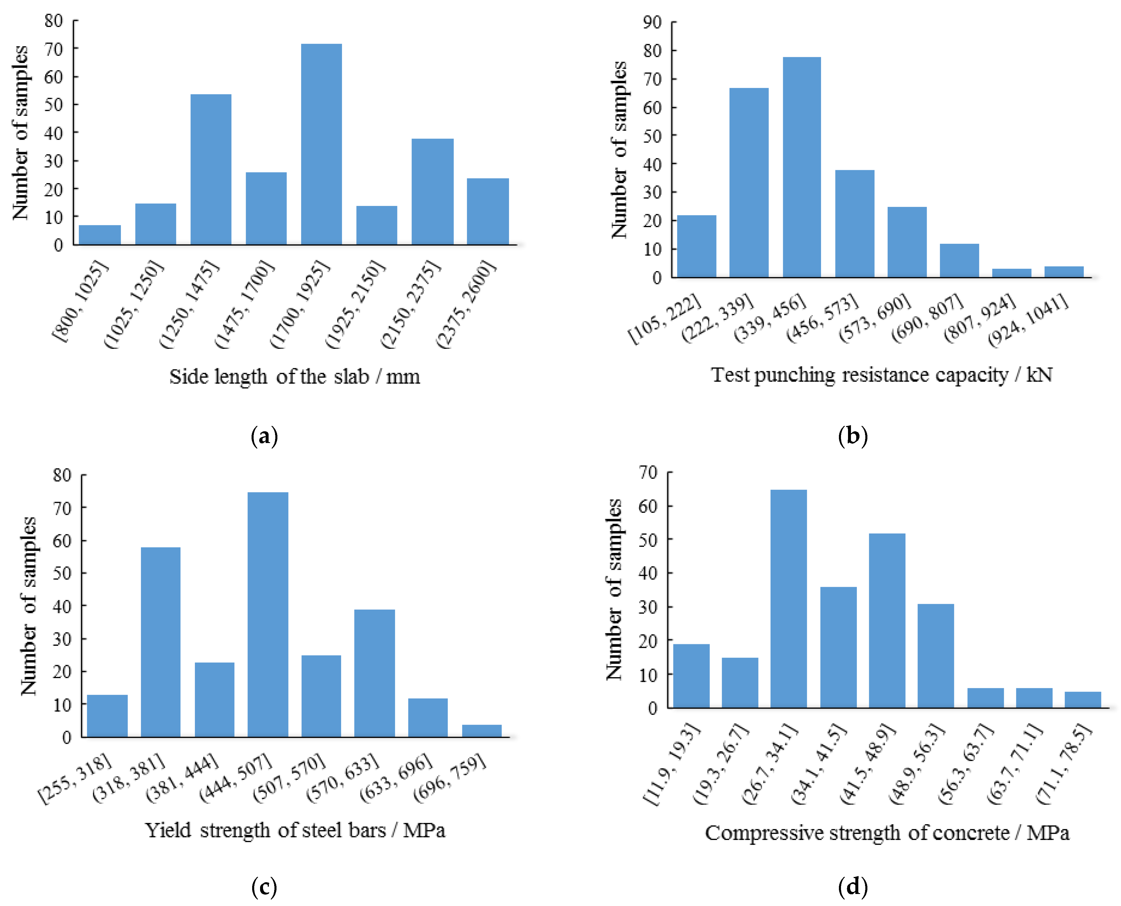
The database established in this paper has the characteristic of a small amount of extreme data and adequate specimens. It is suitable for the various research aspects of the slab–column joints without punching shear reinforcement in further work.
(2)
There are some differences in the parameters included in the design codes. The design codes proposed in this paper all consider the relative of punching shear capacity with the concrete strength. Where only GB50010 [49] uses tensile strength in the equation, the other design codes use compressive strength. Moreover, only EC2 [52] and JSCE [53] consider the effects of reinforcement ratio for punching shear. Other parameters, such as the position of the column, the size effect and the critical perimeter are not the same.
(3)
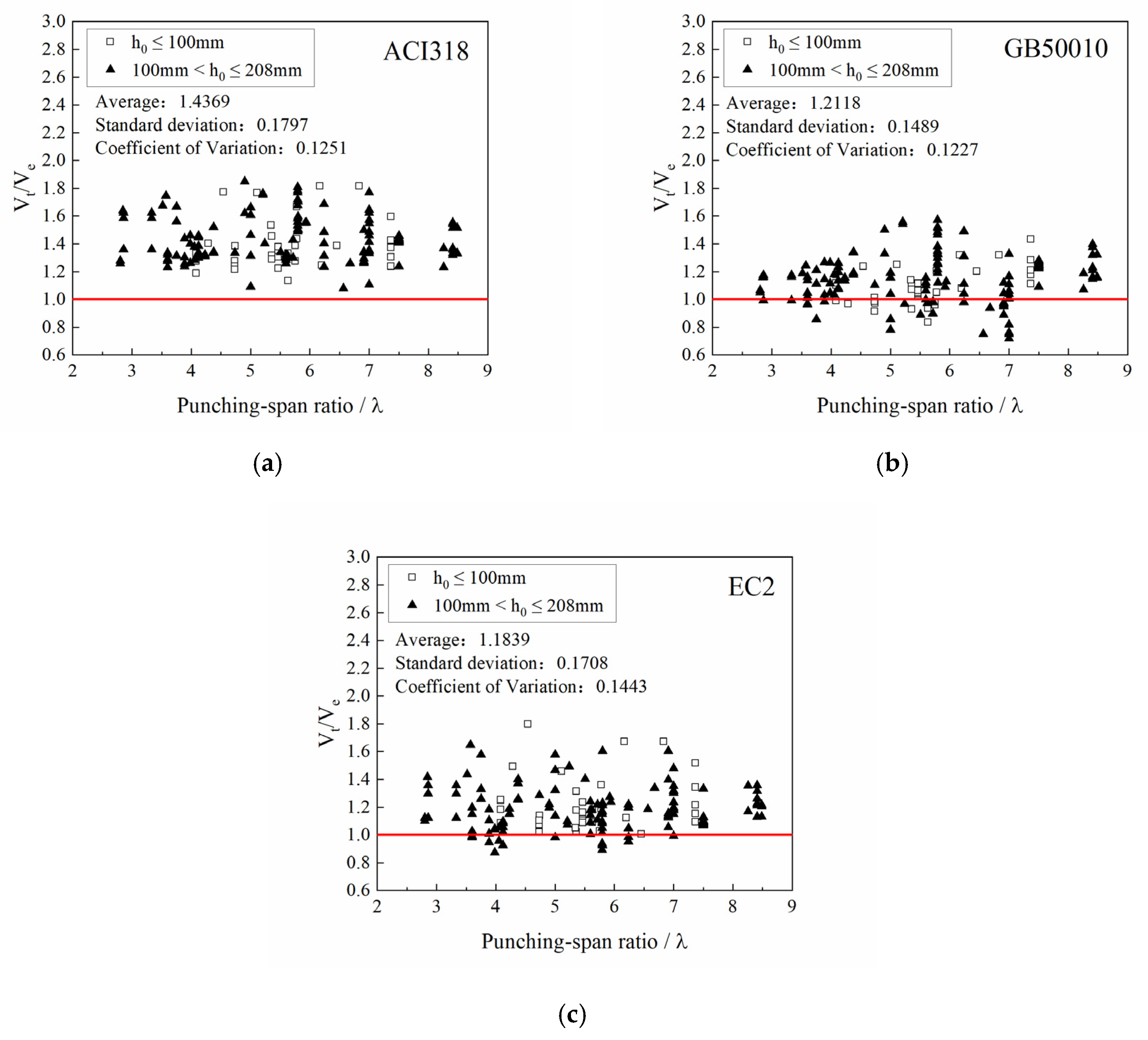
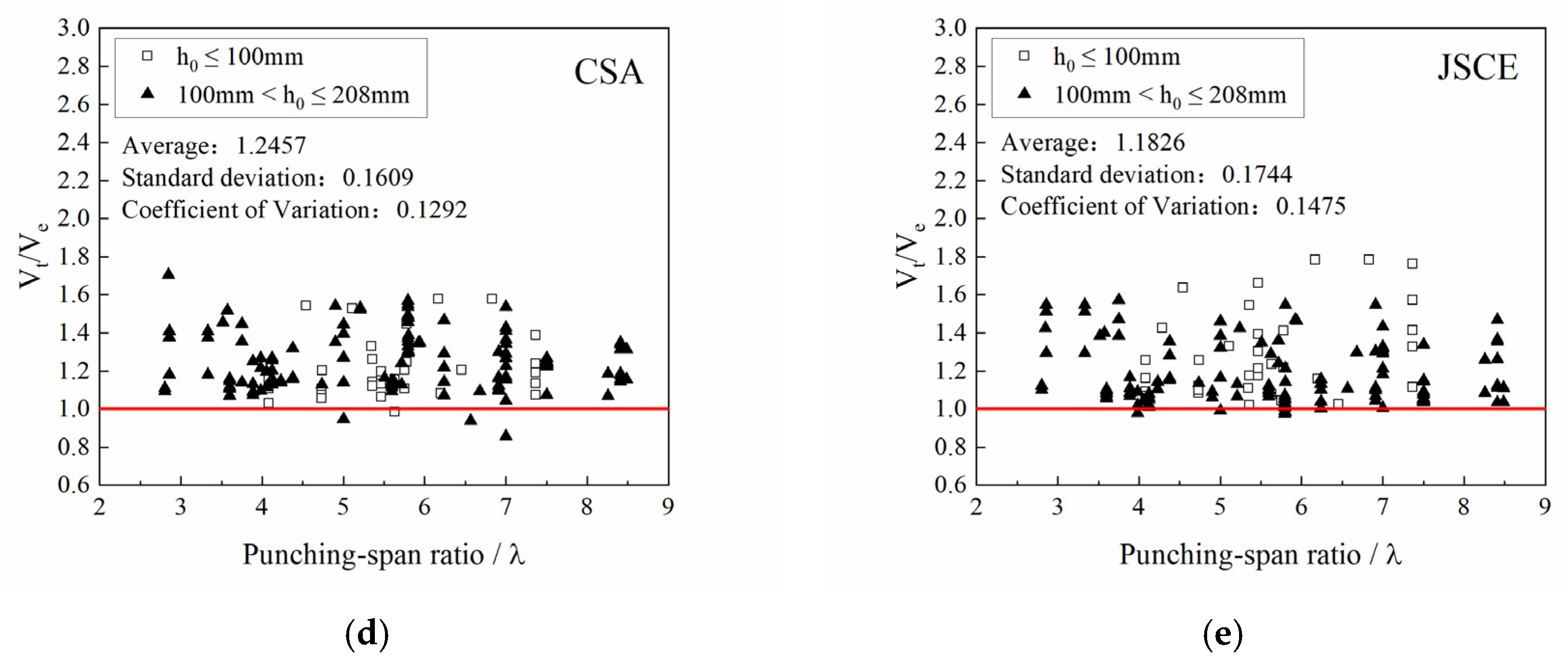
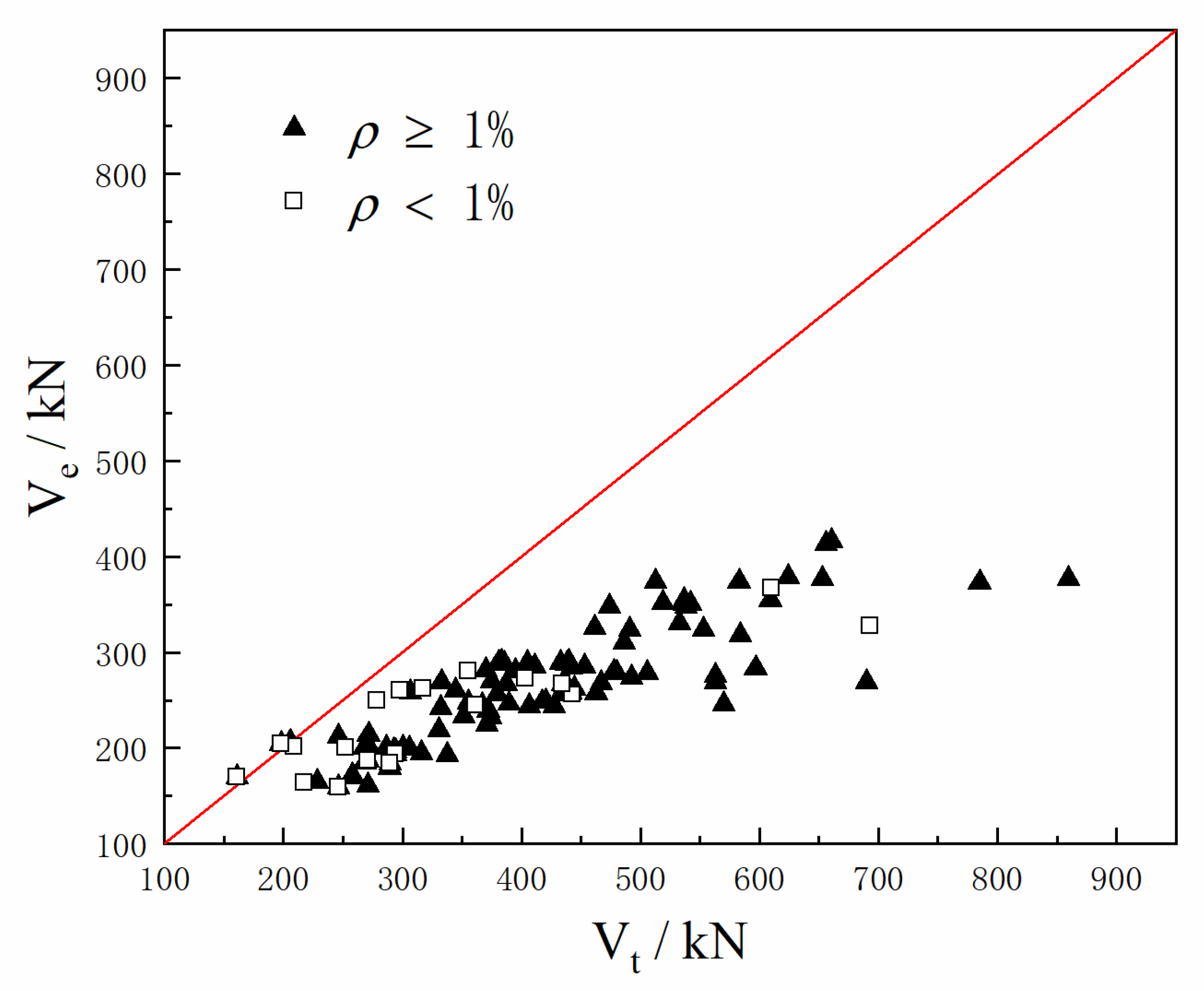
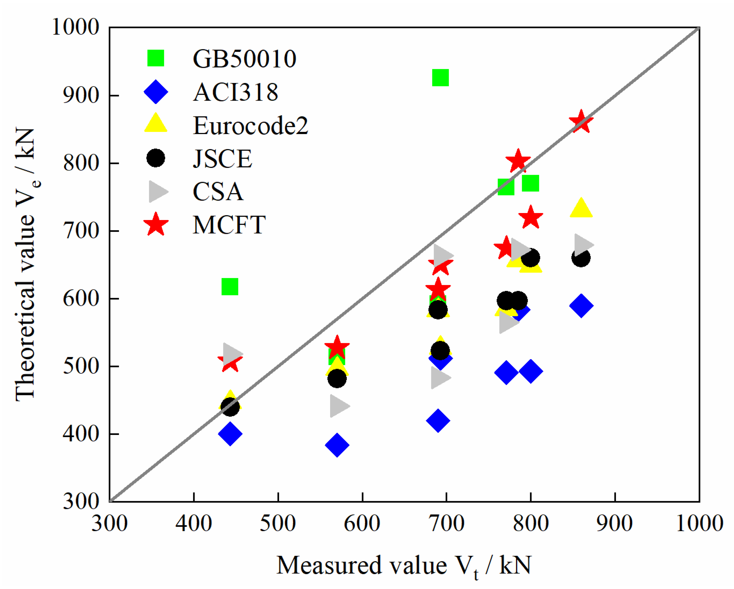
Design codes have different results in predicting punching shear for the database in this paper. ACI318 [50] has a relatively small coefficient of variation and a low degree of discreteness. But the predicting values are visibly higher than the experimental results which indicate conservative results. JSCE [53] has a large coefficient of variation. EC2 [52] has a large dispersion, but the average value is the smallest of other design codes. GB50010 [49] has a small dispersion and average value, but the applicable range of the equation is small.
(4)
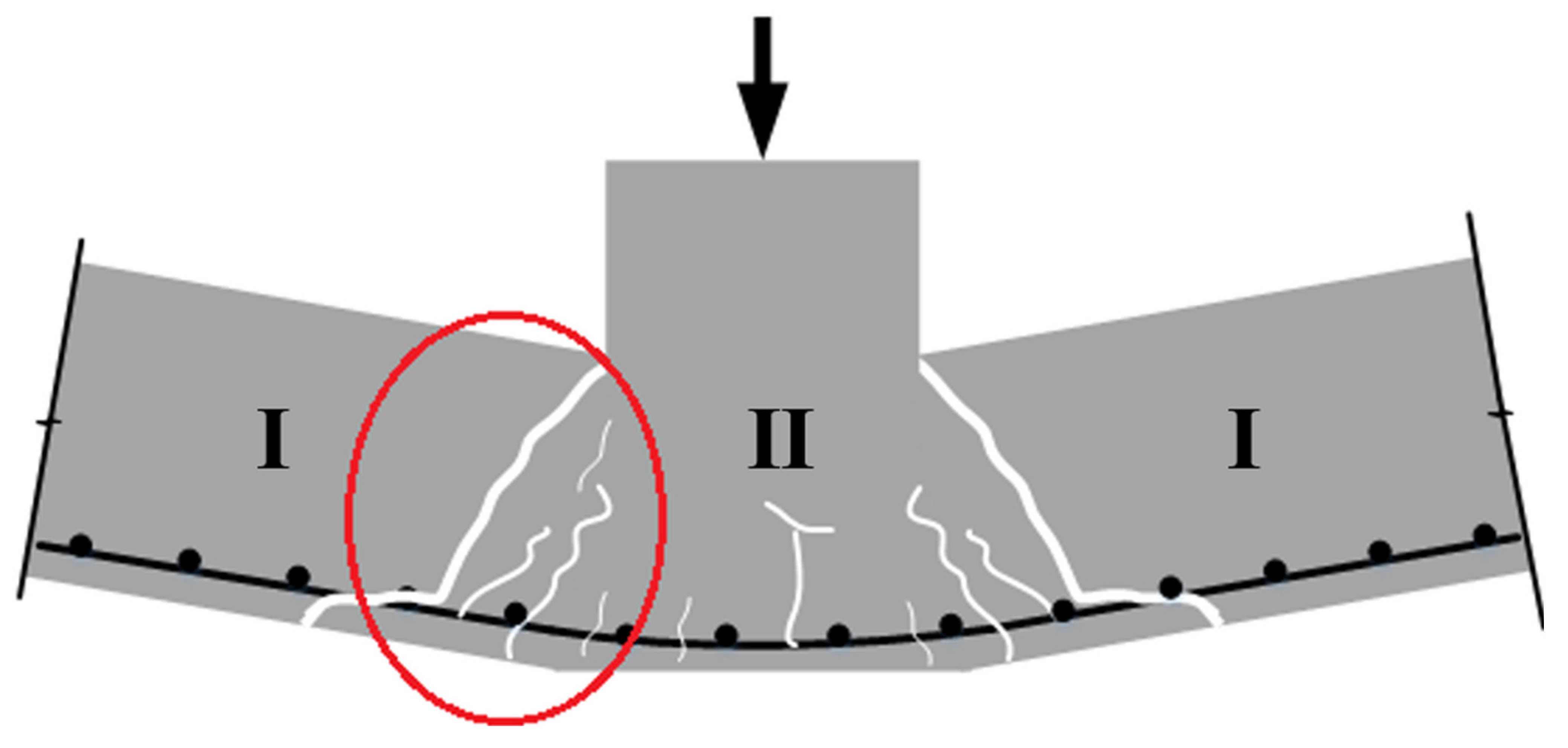
The punching shear failure criterion of RC slab–column (within vertical load) without punching shear reinforcement proposed are combined the shear diagonal tension failure of RC beams with a large shear-to-span ratio, and the failure is caused by the direct stress and shear stresses in the concrete.
(5)
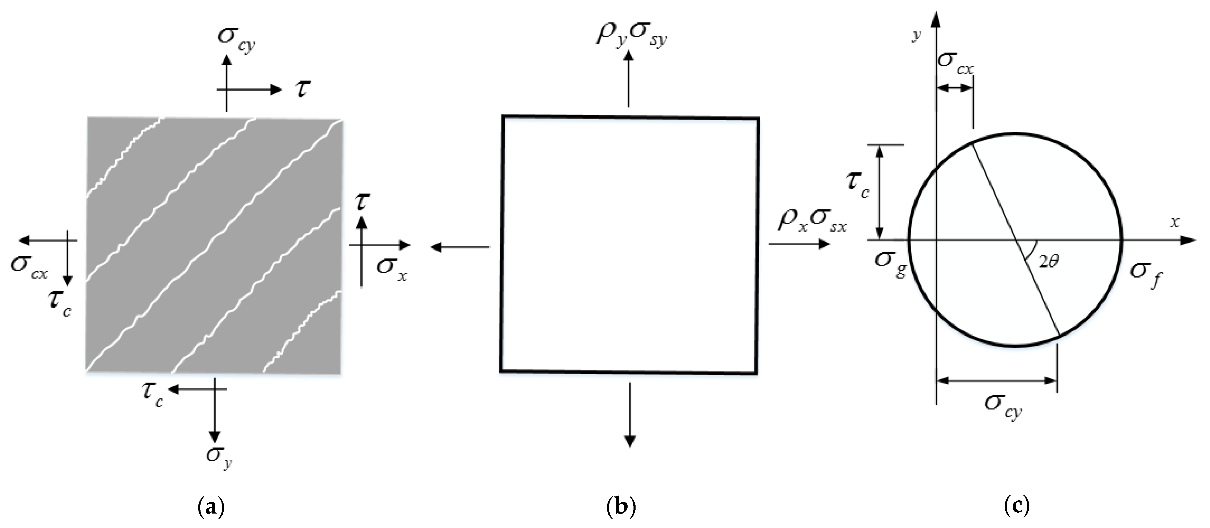
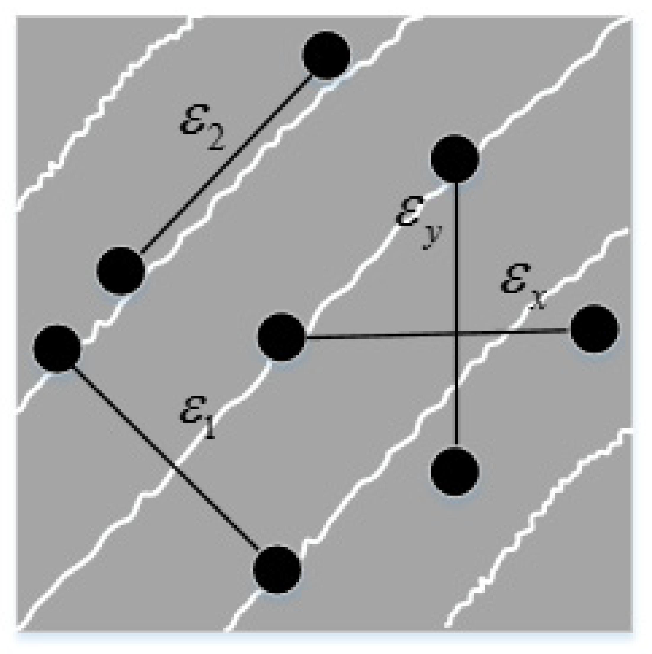
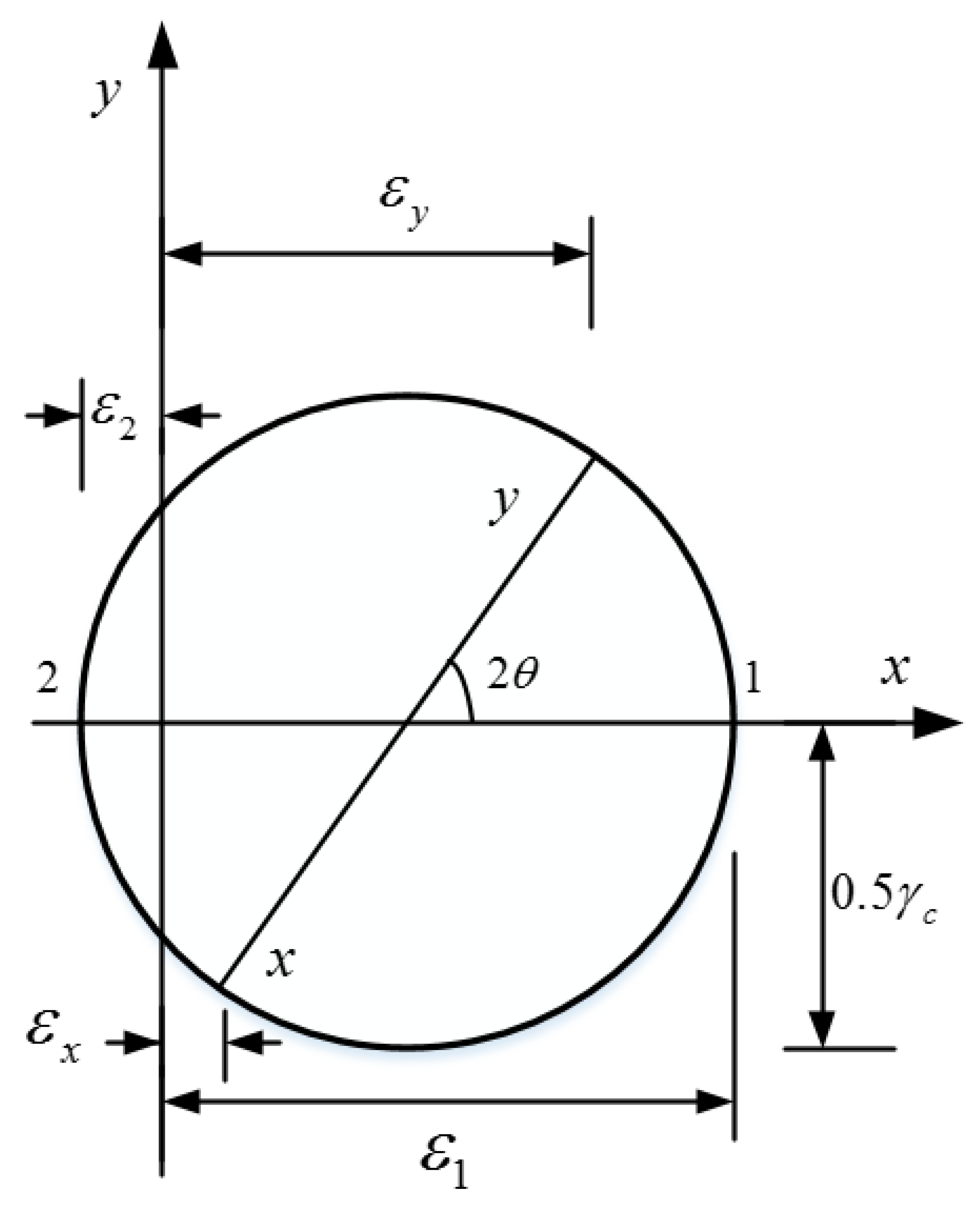
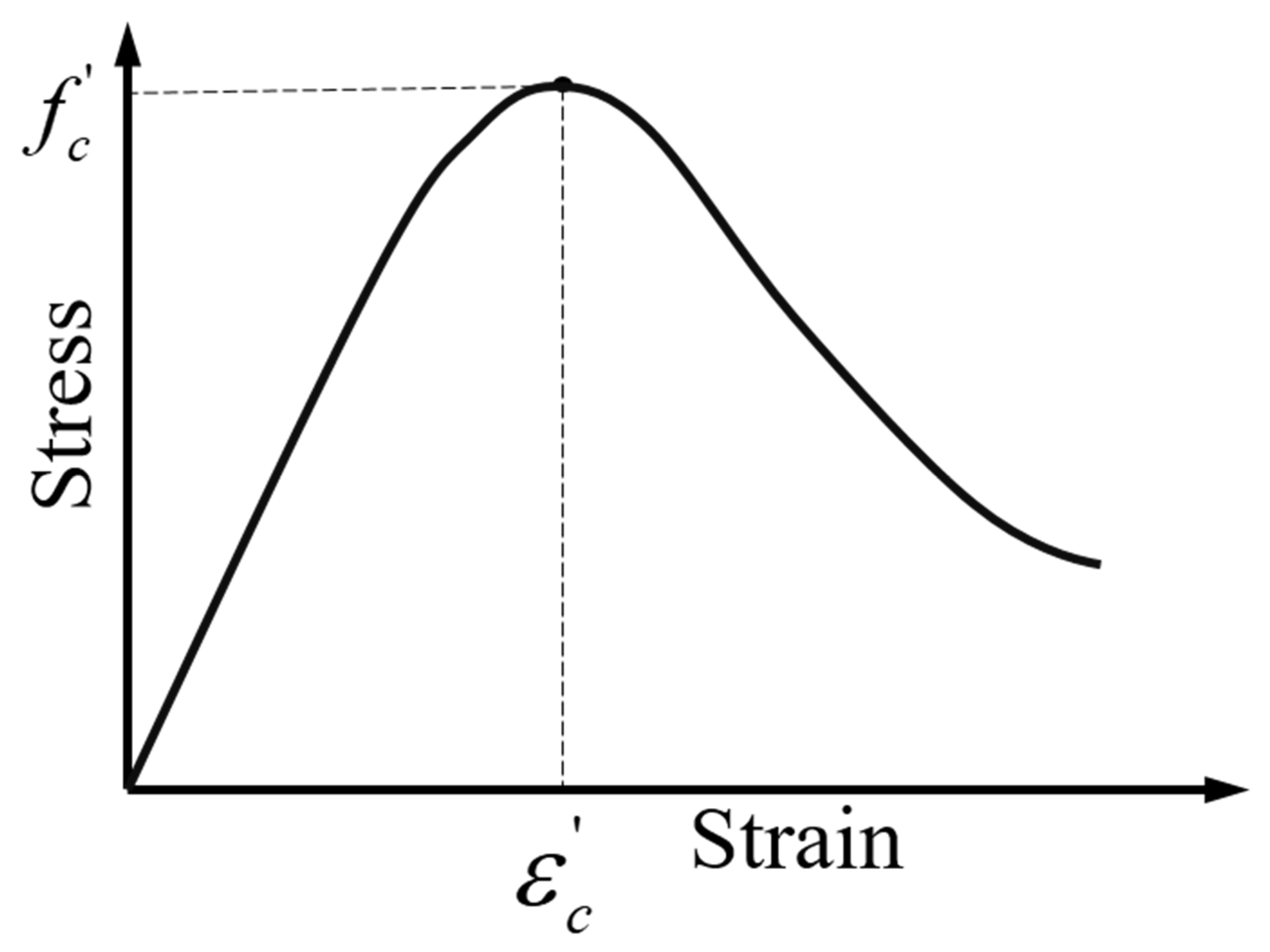
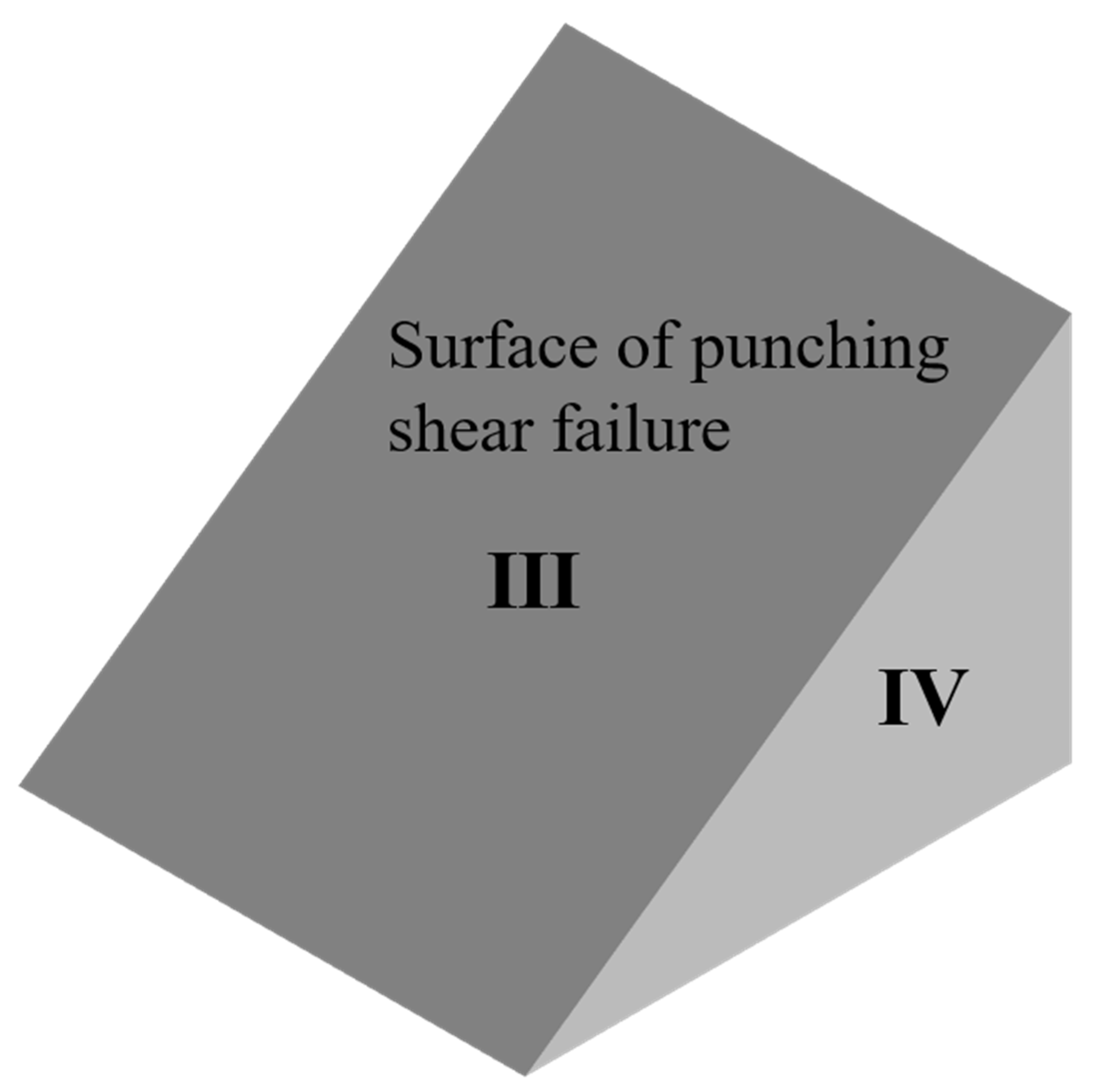
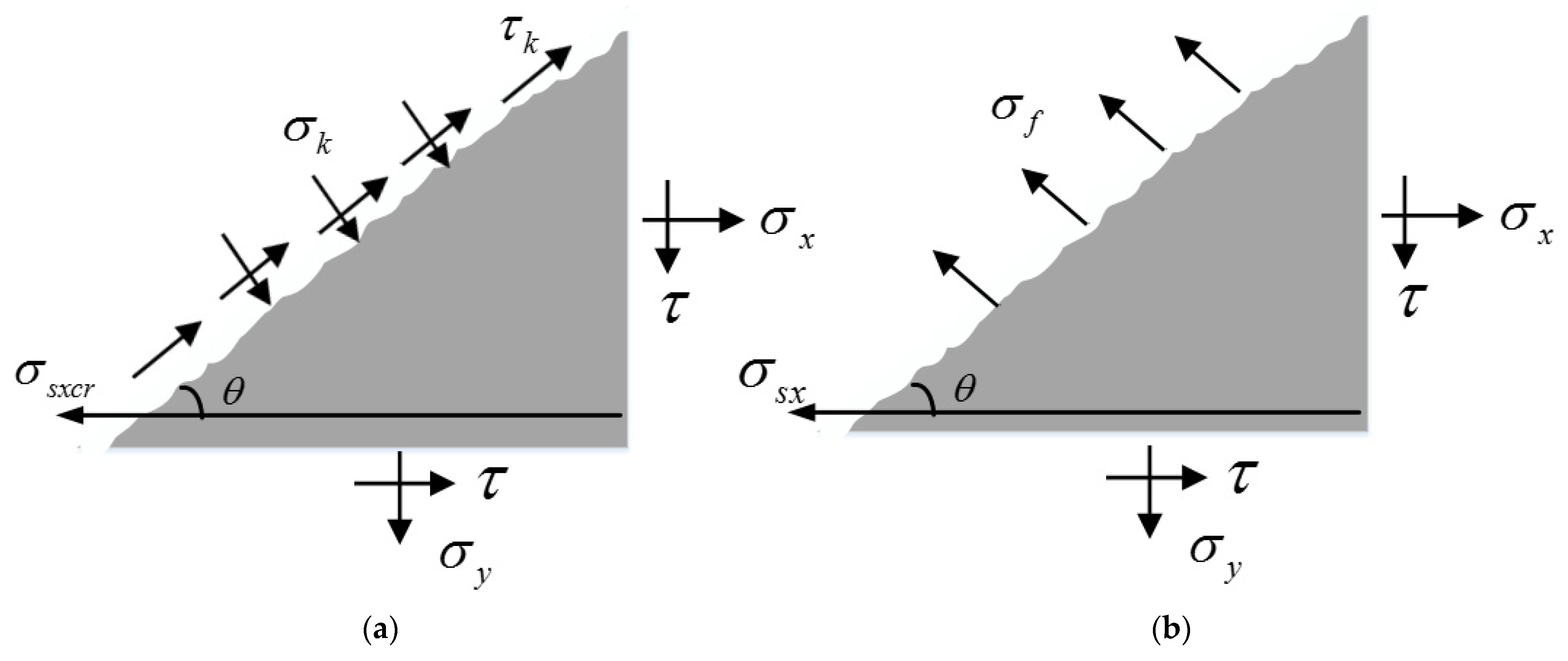
The model of MCFT can be used to predict the punching shear is based on three assumptions, which are essential to transform the three-dimensional mechanics into two-dimensional planar mechanics. The punching shear strength is decided by integrating the stress on the punching surfaces, which is proposed by the stress state of the cracked concrete units in the critical shear crack.
(6)
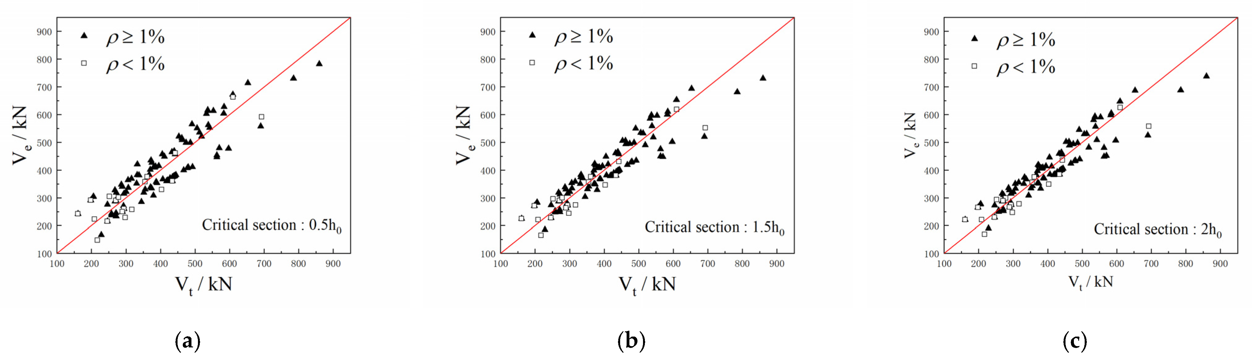
The punching shear capacity equation established based on the MCFT model has limitations before being modified, which is conservative. To ensure the accuracy of the equation, a regression analysis is also applied according to the database. It is shown by the comparison between existing design codes and the proposed model that the model is more accurate when the reinforcement ratio and critical section are considered. The characteristic of the equation established in this paper is that both have reliable theoretical support and summaries of a large number of test results, as well as high prediction accuracy and low dispersion.

Author Contributions

Conceptualization, L.W. and S.L.; methodology, L.W. and S.L.; formal analysis, L.W., T.H., Y.T. and S.L.; investigation, L.W., T.H., Y.T. and S.L.; resources, L.W., Y.T. and S.L.; data curation, L.W.; writing—original draft preparation, L.W., Y.T. and S.L.; writing—review and editing, S.L.; visualization, S.L.; supervision, S.L.; project administration, S.L. All authors have read and agreed to the published version of the manuscript.

Funding

This research was funded by Science Foundation of Zhejiang Province of China, grant number LY22E080016; National Science Foundation of China, grant number 51808499.

Institutional Review Board Statement

Not applicable.

Informed Consent Statement

Not applicable.

Data Availability Statement

Not applicable.

Acknowledgments

This work is supported by Zhejiang Sci-Tech University, who provided administrative and technical support.

Conflicts of Interest

The authors declare no conflict of interest.

References

  1. Park, H.G.; Choi, K.G.; Lan, C. Strain-based strength model for direct punching shear of interior slab-column connections. Eng. Struct. 2011, 33, 1062–1073. [Google Scholar] [CrossRef]
  2. Ruiz, M.F.; Muttoni, A. Applications of Critical Shear Crack Theory to Punching of Reinforced Concrete Slabs with Transverse Reinforcement. ACI Struct. J. 2009, 106, 485–494. [Google Scholar] [CrossRef]
  3. Kadhum, M.M.; Harbi, S.M.; Khamees, S.S.; Abdulraheem Mustafa, S.; Farsangi, E.N. Punching shear behavior of flat slabs utilizing reactive powder concrete with and without flexural reinforcement. Pract. Period. Struct. Des. Constr. 2021, 26, 04020060. [Google Scholar] [CrossRef]
  4. Menna, D.W.; Genikomsou, A.S. Punching shear response of concrete slabs strengthened with ultrahigh-performance fiber-reinforced concrete using finite-element methods. Pract. Period. Struct. Des. Constr. 2021, 26, 04020057. [Google Scholar] [CrossRef]
  5. Hueste, M.B.D.; Wight, J.K. Nonlinear punching shear failure model for interior slab-column connections. J. Struct. Eng. 1997, 9, 997–1008. [Google Scholar] [CrossRef]
  6. Li, D.G.; Shu, Z.F.; Yu, Z.W. Experimental study on the punching shear strength of reinforced concrete slab-column connections without punching shear reinforcement. J. Hunan Univ. 1986, 8, 22–35. [Google Scholar]
  7. Zhen, J.L.; Zhen, Z.J. Experimental research on punching shear strength of reinforced concrete slab. J. Fuzhou Univ. Nat. Sci. Ed. 1992, 2, 65–69. [Google Scholar]
  8. Koppitz, R.; Kenel, A.; Keller, T. Effect of punching shear on load-deformation behavior of flat slabs. Eng. Struct. 2014, 80, 444–457. [Google Scholar] [CrossRef]
  9. Vakhshouri, B.; Nejadi, S. Instantaneous deflection of light-weight concrete slabs. Front. Struct. Civ. Eng. 2017, 11, 412–423. [Google Scholar] [CrossRef]
  10. Milligan, G.J.; Polak, M.A.; Zurell, C. Finite element analysis of punching shear behaviour of concrete slabs supported on rectangular columns. Eng. Struct. 2020, 224, 111189. [Google Scholar] [CrossRef]
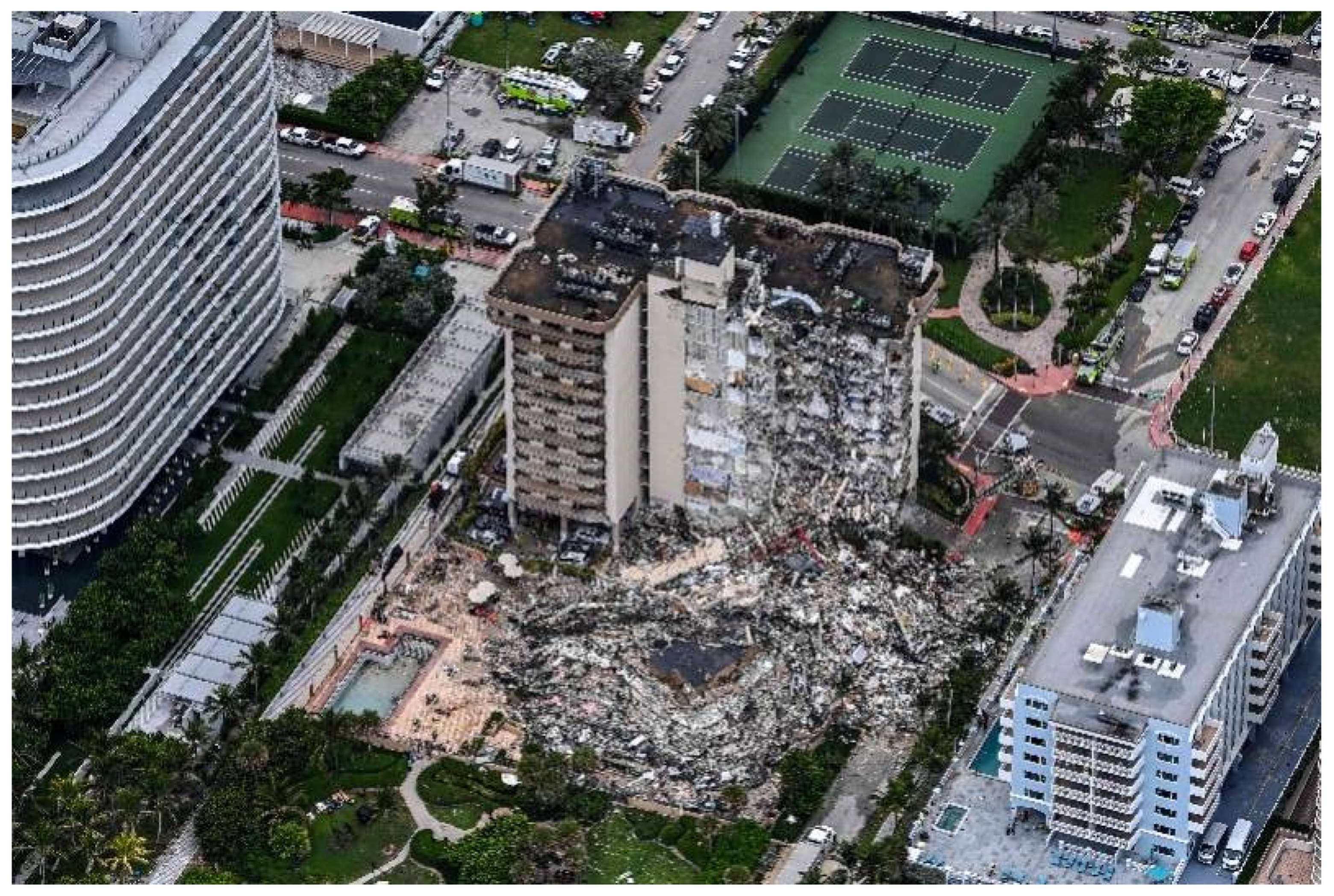
  11. Lu, X.; Guan, H.; Sun, H.; Li, Y.; Zuo, L. A preliminary analysis and discussion of the condominium building collapse in surfside, Florida, US, June 24, 2021. Front. Struct. Civ. Eng. 2021, 15, 1097–1110. [Google Scholar] [CrossRef]
  12. Broms, C.E. Elimination of flat plate punching failure mode. ACI Struct. J. 2000, 1, 94–101. [Google Scholar] [CrossRef]
  13. Pinto, V.C.; Branco, V.; Oliveira, D.R. Punching in two-way RC flat slabs with openings and L section columns. Eng. Comput. 2019, 36, 2430–2444. [Google Scholar] [CrossRef]
  14. Bazant, Z.P.; Cao, Z. Size effect in punching shear failure of slabs. ACI Struct. J. 1987, 1, 44–53. [Google Scholar]
  15. Hallgren, M. Punching Shear Capacity of Reinforced High Strength Concrete Slabs. Ph.D. Thesis, KTH Royal Institute of Technology, Department of Structural Engineering, Stockholm, Sweden, November 1996. [Google Scholar]
  16. Yankelevsky, D.Z.; Leibowttz, O. Punching shear in concrete slabs. Int. J. Mech. Sci. 1999, 41, 1–15. [Google Scholar] [CrossRef]
  17. Nielsen, M.P.; Hoang, L.C. Limit Analysis and Concrete Plasticity; CRC Press: Boca Raton, FL, USA, 2010. [Google Scholar]
  18. Johansen, K.W. Yield-Line Theory; Cement and Concrete Association: London, UK, 1962. [Google Scholar]
  19. Silva, R.J.C.; Regan, P.E.; Melo, G.S.S.A. Punching of post-tensioned slabs—Tests and codes. ACI Struct. J. 2007, 104, 123–132. [Google Scholar] [CrossRef]
  20. Cai, J.; Lin, F. Ultimate punching shear strength for concrete slabs based on twin-shear strength theory. Eng. Mech. 2006, 23, 110–113. [Google Scholar] [CrossRef]
  21. Huang, C.; Shuang, P.; Ding, B.; Srikanta, P. An analytical punching shear model of RC slab-column connection based on database. J. Intell. Fuzzy Syst. 2018, 35, 469–483. [Google Scholar] [CrossRef]
  22. Long, A.E. Punching failure of slabs—Transfer of moment and shear. J. Struct. Div. 1973, 8, 665–685. [Google Scholar] [CrossRef]
  23. Kinnunen, S.; Nylander, H. Punching of Concrete Slabs without Shear Reinforcement; KTH Royal Institute of Technology: Stockholm, Sweden, 1960. [Google Scholar]
  24. Broms, C.E. Concrete Flat Slabs and Footings—Design Method for Punching and Detailing for Ductility. Ph.D. Thesis, KTH Royal Institute of Technology, Stockholm, Sweden, 2005. [Google Scholar]
  25. Walraven, J.C. Fundamental analysis of aggregate interlock. J. Struct. Div. 1981, 11, 2245–2270. [Google Scholar] [CrossRef]
  26. Guandalini, S.; Burdet, O.; Muttoni, A. Punching tests of slabs with low reinforcement ratios. ACI Struct. J. 2009, 106, 87–95. [Google Scholar] [CrossRef]
  27. Pani, L.; Ftochino, F. Punching of reinforced concrete slab without shear reinforcement: Standard models and new proposal. Front. Struct. Civ. Eng. 2020, 48, 21–34. [Google Scholar] [CrossRef]
  28. Zaghlool, E.R.F.; Paiva, H.A.R.D. Tests of flat-plate corner column-slab connections. J. Struct. Div. 1973, 3, 551–572. [Google Scholar] [CrossRef]
  29. Bentz, E.C.; Vecchio, F.J.; Collins, M.P. Simplified modified compression field theory for calculating shear strength of reinforced concrete elements. ACI Struct. J. 2007, 103, 614–624. [Google Scholar]
  30. Urban, T.; Goldyn, M.; Krawczyk, L.; Sowa, L. Experimental investigations on punching shear of lightweight aggregate concrete flat slabs. Eng. Struct. 2019, 197, 109371. [Google Scholar] [CrossRef]
  31. Goldyn, M.; Krawczyk, L.; Ryzynski, W.; Urban, T. Experimental inverstigations on punching shear of falt slabs made from lightweight aggregate concrete. Arch. Civ. Eng. 2018, 64, 293–306. [Google Scholar] [CrossRef] [Green Version]
  32. Sun, J.J.; Yang, Q.N.; Mao, M.J.; Zhang, W.B. Effect of punching shear-span ratio on punching strength of reinforced concrete slab. Ind. Constr. 2018, 48, 84–88. [Google Scholar] [CrossRef]
  33. Caratelli, A.; Imperatore, S.; Meda, A.; Rinaldi, Z. Punching shear behavior of lightweight fiber reinforced concrete slabs. Compos. Part B Eng. 2016, 99, 257–265. [Google Scholar] [CrossRef]
  34. Carmo, R.N.F.; Costa, H.; Rodrigues, M. Experimental study of punching failure in LWAC slabs with different strengths. Mater. Struct. 2016, 49, 2611–2626. [Google Scholar] [CrossRef]
  35. Youm, K.S.; Kim, J.J.; Moon, J. Punching shear failure of slab with lightweight aggregate concrete (LWAC) and low reinforcement ratio. Constr. Build. Mater. 2014, 65, 92–102. [Google Scholar] [CrossRef]
  36. Peng, J. Experimental Research on Punching Shear Resistance of Reinforced Concrete Slab-Column Joints. Master’s Thesis, Hunan University, Changsha, China, 2013. [Google Scholar]
  37. Yang, J.M.; Yoon, Y.S.; Cook, W.D.; Mitchell, D. Punching shear behavior of two-way slabs reinforced with high-strength steel. ACI Strcutural J. 2010, 4, 468–475. [Google Scholar] [CrossRef]
  38. Widianto; Bayrak, O.; Jirsa, J.O. Two-way shear strength of slab-column connections: Reexamination of ACI 318 provisions. ACI Struct. J. 2009, 106, 160–170. [Google Scholar]
  39. Zhang, Y.W. Experimental Research on Punching Shear Resistance of Reinforced Concrete Slabs. Master’s Thesis, Hunan University, Changsha, China, 2010. [Google Scholar]
  40. Lee, J.-H.; Yoon, Y.-S.; Lee, S.-H.; Cook, W.D.; Mitchell, D. Enhancing performance of slab-column connections. J. Struct. Eng. 2008, 3, 448–457. [Google Scholar] [CrossRef]
  41. Teng, S.; Cheong, H.K.; Kuang, K.L.; Geng, J.Z. Punching shear strength of slabs with openings and supported on rectangular columns. ACI Struct. J. 2004, 5, 678–687. [Google Scholar] [CrossRef]
  42. Ospina, C.E.; Alexander, S.D.; Roger, C.J.J. Punching of two-way concrete slabs with fiber-reinforced polymer reinforcing bars or grids. ACI Struct. J. 2003, 82, 431–446. [Google Scholar] [CrossRef]
  43. Reineck, K.H.; Kuchma, D.A.; Kang, S.K.; Marx, S. Shear database for reinforced concrete members without shear reinforcement. ACI Struct. 2003, 2, 240–249. [Google Scholar] [CrossRef]
  44. Liu, G.Y.; Liu, X.D. Experimental research on punching problem of plate with anti-punching bent ribs. J. Harbin Inst. Civ. Eng. Archit. 1994, 3, 47–52. [Google Scholar]
  45. An, Y.J.; Zhao, G.F. Experimental research on the punching shear resistance of reinforced steel fiber concrete slabs. J. Build. Struct. 1994, 2, 11–14. [Google Scholar]
  46. Marzouk, A.H.H. Punching shear analysis of reinforced high-strength concrete slabs. Can. J. Civ. Eng. 1991, 5, 954–963. [Google Scholar] [CrossRef]
  47. Regan, P.E. Symmetric punching of reinforced concrete slabs. Mag. Concr. Res. 1986, 136, 115–128. [Google Scholar] [CrossRef]
  48. Mowrer, R.D.; Vanderbilt, M.D. Shear strength of lightweight aggregate reinforced concrete flat plates. ACI Struct. J. 1967, 64, 722–729. [Google Scholar] [CrossRef]
  49. GB50010-2010 (2015); Code for Design of Concrete Structures. Ministry of Housing and Urban-Rural Development: Beijing, China, 2015.
  50. ACI-318 (2019); Committee 318—Building Code Requirements for Structural Concrete (ACI 318-19) and Commentary on Building Code Requirements. American Concrete Institute: Farmington Hills, MI, USA, 2019.
  51. CSA (2019); Design of Concrete Structures. Canadian Standards Association: Rexdale, ON, Canada, 2019.
  52. EC2 (2004); EN 1992-1-1:2004: Eurocode 2: Design of Concrete Structures—Part 1-1: General Rules and Rules for Buildings. National Standards Authority of Ireland: Dublin, Ireland, 2014.
  53. JSCE Concrete Committee. Standard Specifications for Concrete Structures—2007; Japan Society of Civil Engineers: Tokyo, Japan, 2007. [Google Scholar]
  54. El-Gendy, M.G.; El-Salakawy, E.F. GFRP shear reinforcement for slab-column edge connections subjected to reversed cyclic lateral load. J. Compos. Constr. 2020, 24, 04020003. [Google Scholar] [CrossRef]
  55. Mostofinejad, D.; Jafarian, N.; Naderi, A.; Mostofinejad, A.; Salehi, M. Effects of openings on the punching shear strength of reinforced concrete slabs. Structures 2020, 25, 760–773. [Google Scholar] [CrossRef]
  56. Hassan, M.; Fam, A.; Benmokrane, B.; Ferrier, E. Effect of column size and reinforcement ratio on shear strength of glass fiber-reinforced polymer reinforced concrete two-way slabs. Struct. J. 2017, 114, 937–950. [Google Scholar] [CrossRef]
  57. Zhao, J.; Yi, W.J. Calculation and study on punching bearing capacity of slab-column joints without shear reinforcement. Build. Struct. 2019, 13, 120–131. [Google Scholar] [CrossRef]
  58. Vecchio, F.J.; Collins, M.P. The modified compression-field theory for reinforced concrete elements subjected to shear. ACI J. Proc. 1986, 2, 219–231. [Google Scholar] [CrossRef]
  59. Vecchio, F.J.; Collins, M.P. Predicting the response of reinforced concrete beams subjected to shear using modified compression field theory. ACI Struct. J. 1988, 3, 258–268. [Google Scholar] [CrossRef]
  60. Eladawy, M.; Hassan, M.; Benmokrane, B.; Ferrier, E. Lateral cyclic behavior of interior two-way concrete slab-column connections reinforced with GFRP bars. Eng. Struct. 2020, 209, 109978. [Google Scholar] [CrossRef]
  61. Li, Z.P.; Mao, M.J.; Yang, Q.N. Effect of reinforcement ratio on punching capacity of reinforced concrete bridge deck. Ind. Constr. 2020, 50, 44–51. [Google Scholar] [CrossRef]
  62. Chen, W.J.; Bian, J.J.; Wang, N.; Su, Y.P. Punching shear capacity analysis of a slab-column connection considering the effect of different reinforcement ratios. China Earthq. Eng. J. 2016, 38, 525–532. [Google Scholar] [CrossRef]
  63. Yi, W.J.; Hong, F.; Peng, J. Experimental investigation of punching shear failure of reinforced concrete slab-column conections. Build. Struct. 2016, 46, 11–18. [Google Scholar] [CrossRef]
Figure 1. Collapsed condominium building (photo via Agence France-Presse) [11].
Buildings 12 00226 g001
Figure 2. Distribution of specimens: (a) Side length of the slab; (b) Test punching resistance capacity; (c) Yield strength of reinforcement; (d) Compressive strength of concrete; (e) Reinforcement ratio; (f) Effective height; (g) Axial tensile strength of concrete; (h) Side length of column.
Buildings 12 00226 g002aBuildings 12 00226 g002b
Figure 3. Punching shear resistance of different design codes: (a) ACI318; (b) GB50010; (c) EC2; (d) CSA; (e) JSCE.
Buildings 12 00226 g003aBuildings 12 00226 g003b
Figure 4. Stress state of RC element and average stress Mohr circle: (a) Cracked concrete element; (b) Reinforcement element; (c) Mohr circle.
Buildings 12 00226 g004
Figure 5. Strain of cracked concrete element.
Buildings 12 00226 g005
Figure 6. Mean strain Mohr circle.
Buildings 12 00226 g006
Figure 7. The stress-strain relationships of concrete.
Buildings 12 00226 g007
Figure 8. The stress-strain relationships of reinforcement.
Buildings 12 00226 g008
Figure 9. Schematic diagram of punching failure.
Buildings 12 00226 g009
Figure 10. The prism free-body of punching shear failure.
Buildings 12 00226 g010
Figure 11. Stress at the crack: (a) Crack local stress; (b) Average stress.
Buildings 12 00226 g011
Figure 12. Calculation result of the uncorrected bearing capacity equation.
Buildings 12 00226 g012
Figure 13. Punching shear capacity of different critical section perimeter: (a) um = 4 (c + h0 ); (b) um = 4 (c + 3h0 ); (c) um = 4 (c + 4h0 ).
Buildings 12 00226 g013
Figure 14. Comparison of MCFT with design codes.
Buildings 12 00226 g014
Table 1. Design codes for punching shear resistance.
Design CodesPunching Shear Strength
GB50010 [49] V G B = 0.7 β h f t η u m h 0 η = min { η 1 = 0.4 + 1.2 β s η 2 = 0.5 + α s h 0 4 u m
ACI318 [50] V A C I 1 = 0.17 ( 1 + 2 β s ) ξ f c u m h 0   V A C I 2 = 0.083 ( a s h 0 u m + 2 ) ξ f c u m V A C I 3 = 0.33 ξ u m h 0 f c
CSA [51] V C S A = min { 0.38 f c u m h 0 ,   0.19 ( 1 + 2 β c ) f c u m h 0 ,   ( 0.19 + α s c h 0 u m ) f c u m h 0 }
JSCE [53] V J S C E = β c β p β r f p u m h 0 β d = 1000 / h 0 4 1.5   β p = ( 100 ρ ) 1 / 3 1.5
β r = 1 + 1 / ( 1 + 0.25 u m / h 0 )   f p = 0.2 ( f c ) 1 / 2 1.2
EC2 [52] V E C = 1 s c [ 0.18 k ( 100 ρ f c ) 1 / 3 0.1 σ ] u m h 0 1 s c u m h 0 ( 0.028 k 3 / 2 f c 0.1 σ ) k = 1 + ( 200 / h 0 ) 0.5 2
ρ = ( ρ x ρ y ) 0.5 2 %
The section height influence coefficient β h = 1.0 ; η 1 is the influence coefficient of the shape of loaded area; η 2 is the influence coefficient ( u m / h 0 ); u m is the critical perimeter; (The critical section does not consider the angle). β s is the ratio of long side to short side ( 2 β s 4 for GB50010 [49]); α s is the column position influence coefficient, which is taken as 40, 30, 20 for the inner, edge and corner column; α s e is taken as 1.15, 1.4, 1.5 for the inner, edge and corner column. α s e is taken as 4, 3, 2 for the inner, edge and corner column; ξ is the size effect factor, which is taken 1 (normal weight concrete) or 0.75 (lightweight concrete); k is the size effect coefficient.
Table 2. Comparison between various punching shear equations.
ParameterACI318 [50]GB50010 [49]EC2 [52]CSA [51]JSCE [53]
Compressive strength of concrete 0.33 f c f t ( f c ) 1 / 3 0.38 f c 0.2 f c
Ratio of flexure reinforcement// ρ 1 / 3 / ρ 1 / 3
Location of critical section 0.5 h 0 0.5 h 0 2 h 0 0.5 h 0 0.5 h 0
Size effect//
Column position//
Table 3. Comparison of punching shear resistance between various design codes.
Design CodesAverage Value of V t / V e Standard DeviationCoefficient of VariationMaxMinValue of Max–MinOver-Average Percentage
ACI318 [50]1.43690.17970.12001.85391.07840.757539.04%
GB50010 [49]1.21180.14890.12271.57180.71780.854032.67%
EC2 [52]1.18390.17080.14431.68380.87250.811336.65%
CSA [51]1.24570.16090.12921.70340.85490.848535.46%
JSCE [53]1.18260.17440.14751.81240.97580.836640.63%
Table 4. Comparison of punching shear with different critical section perimeter.
Critical Section Position α Average RatioStandard DeviationCoefficient Of VariationOver-Average Percentage
0.5 h 0 2.601.000.1802470.18024739.8%
1.5 h 0 1.561.000.1489220.14892242.3%
2.0 h 0 1.301.000.1391130.13911342.3%
Table 5. Specimens parameters.
Number h 0 / mm f c / MPa ρ f y / MPa λ V t / kN
C70-30-1 [63]15032.290.86%604.07443
C70-30-1 [63]15029.691.28%604.07570
C70-30-1 [63]15035.561.73%453.67690
C70-30-1 [63]15052.960.86%604.07693
C70-30-1 [63]15048.561.28%604.07771
C70-30-1 [63]15048.981.73%453.67800
Publisher’s Note: MDPI stays neutral with regard to jurisdictional claims in published maps and institutional affiliations.

