1. Introduction
A vibration isolation system is essentially a device that enables the dissipation of vibrations. This technology can be used in various industrial applications such as heavy machinery, buildings, and even household items like washing machines or refrigerators. In addition, vibration isolation systems are used to mitigate environmental vibrations. This technology aims to reduce the transmission and propagation of energy from one place to another, providing a safer and more comfortable environment for people who work or live around machinery that produces excessive vibration.
Failure of vibrating machinery, especially rotating ones, has been the primary reason for industrial accidents, human injuries, and fatalities. Uncontrolled machine vibrations can be transmitted through nearby walls and cause structural damage leading to severe human injuries. Therefore, installing vibration isolators and other protective systems is essential.
Klembczyk [
1] discussed the costs of using vibration isolation systems and how many companies are still not adhering to these essential safety measures. According to Klembczyk [
1], the companies which use this technology ultimately protect their employees and ensure a safe workplace. In addition, another study conducted by Simmons [
2] found that despite the awareness of vibration control products, a large percentage of companies were still not using these systems. The company that conducted the study found this to be unacceptable. They put their workers at significant risk due to machines and equipment with no vibration isolator installed. A vibration isolator’s proper use and application require a sound knowledge of the design principles and proper installation techniques. Furthermore, it is essential to understand the application requirements before selecting an appropriate product. Several important factors should be considered when choosing an isolator, such as its capacity rating (e.g., in pounds), frequency range (e.g., from 10–250 Hz), and isolation method (such as rubber, air, springs, and fluid).
A vibration analysis should be conducted to determine the appropriate isolator type as part of the design process. Vibration isolators are standard in many industries, such as power generation, oil and gas, mining, and construction. Vibration control products are also helpful in reducing effects of natural origin, such as earthquakes, or artificial ones such as explosions. Technical disciplines such as elevator lifting, mine hoisting, and suspension bridges use wire ropes. These cables consist of helically twisted wires laid around a core to form strands, eventually weaved together. The efficiency of wire ropes for these particular areas of use can be attributed to their inherent benefits, which are nonlinearity in the force-displacement relation and the energy-absorbing capability.
Velinsky [
3,
4,
5] and his studies have reported nonlinearity in its force-displacement behavior. Another determinant of wire rope characteristics is found, according to Ni et al. [
6,
7], by observing the inherent frictional damping mechanism. This article intends to explore what would constitute practical wire rope applications; one of the most important properties is its flexural rigidity. Tinker and Cutchins [
8] commented on this property with examples of how stiffness determines load-carrying ability, whereas Ni et al. [
6,
7] stated that wire ropes are suitable for energy dissipation.
Friction creates damping, which has “effective applications” for shock or vibration control, as Tinker and Cutchins [
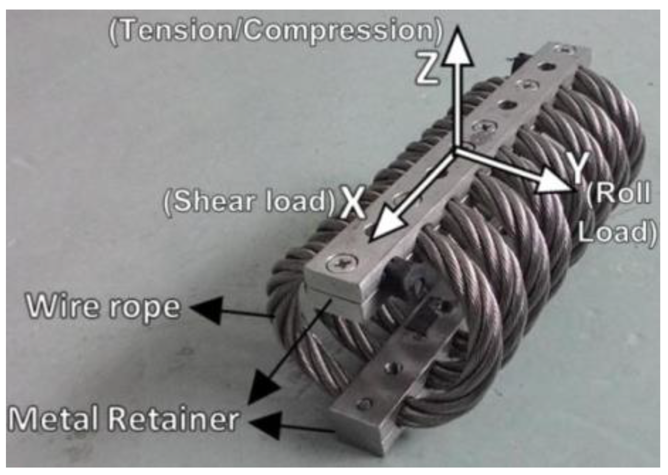
8] noticed in two examples of rocket engines dissipating 70% of energy at critical moments to avoid catastrophic events towards the end. An affordable and lightweight vibration control device such as wire rope is worth studying since it can be used on various scales, has nonlinearity in force-displacement relation, and has an inherent damping capability. A wire rope isolator (WRI) consists primarily of wire ropes (
Figure 1); its main response components are stiffness (hardening through the geometric arrangement commonly found for this type of application) and damping (generated by the inherent frictional tension caused between wires) [
4,
6]. The monotonic loading test can be performed for the static stiffness of a WRI in each direction. The WRI static stiffness possesses the details of the hardening and softening nature of wire ropes at increasing deformations. Most research on WRIs has focused on cyclic loading behavior, but minimal research is available on static stiffness. Ni et al. [
7] identified that the WRI static stiffness depends on the wire rope properties and geometric characteristics, and there is a need for an analytical model with these parameters, but the available literature lacks in-depth work on the stiffness characteristics of WRIs. Tse et al. [
9] developed a stiffness model for Elliptical Leaf Springs (ELS) using Castigliano’s second theorem, which enables the application of a similar methodology to establish the stiffness characteristics of WRIs.
The WRI exhibits a hysteresis behavior under cyclic loading; hysteresis is a natural mechanism for structural and mechanical systems to develop restoring forces against movements and dissipate energy. Tinker and Cutchins [
8] identified how the friction between the wire strands of a WRI dissipates the vibration energy. They found this by studying the hysteresis curve of WRIs against the hysteresis curve of Coulomb friction. Ni et al. [
6] studied the hysteresis behavior of WRIs under cyclic loading. The symmetric hysteresis curve is observed for smaller displacement amplitude, but asymmetric was observed for higher displacement. They also proposed two parameters to analyze the hysteresis curve—effective stiffness and hysteresis area. Demetriades et al. [
11] performed a study on the behavior of WRIs under various loadings. They suggested that the hardening and softening can be due to the wire strands’ interaction under tension and compression loading. Wang et al. [
12] and Ni et al. [
7] studied the influence of displacement amplitude on the effective stiffness and observed that the effective stiffness was reduced at higher displacements. They also observed that the hysteresis area increases with increased displacements. Studies have, interestingly, found that the hysteresis behavior under shear is similar to the hysteresis behavior under roll [
11,
13]. The WRI has been taken for study in earlier works to understand its stiffness and damping properties, and a discussion of the previous studies on WRIs is presented in the
Section 2.
2. Review of Previous Studies on WRIs
Leblouba et al. [
14] presented a study of polycal wire rope isolators (PWRIs), and they tested 12 isolators with different geometries and determined the damping, energy dissipation, and stiffness. The new mathematical model proposed to represent the hysteresis behavior of PWRIs in shear was found to replicate the soft-hardening symmetric hysteresis loops observed in the tests. They observed that all tested PWRIs displayed symmetric, rate-independent, soft-hardening hysteresis behavior. Further, they observed softening behavior at small deformations and hardening behavior at large deformations. The effective stiffness, energy dissipated per cycle, and damping varied with the mechanical and geometrical properties of the isolators. The proposed mathematical model was found to simulate the shear behavior of tested isolators with satisfactory accuracy. Their study concluded that the proposed mathematical model is a suitable tool to represent the hysteresis behavior of PWRIs in shear and can predict the energy dissipation and damping for different geometries and loading rates. In terms of implications, the findings of that study could be used to design more effective PWRIs for use in naval and aerospace structures.
Lee et al. [
15] studied a novel isolation system having separate rubber and wire isolators to understand its dynamic properties. They performed pure shear, compressive, compressive-stress dependence, and shear-strain dependence tests on 22 specimens. They identified that the increase in shear strain increases the energy dissipation but decreases the damping ratio, whereas the increase in compressive stress increases the damping ratio. Furthermore, they also developed a macro-model for the load-displacement response of the isolation system, and the prediction results were in good agreement with the experimental results.
Cen et al. [
16] used finite element analysis (FEA) to create a simplified model of a polycal wire rope isolator. This simplified model was then used to study the vertical static stiffness of the WRI. The results of the FEA showed that the vertical static stiffness of the WRI was reduced as the degree of compression deformation increased. Additionally, the steel wires in the WRI exhibited significant displacement changes when subjected to axial tensile and compress loads. Finally, the authors concluded that the simplified FEA method presented in this paper is an effective tool for studying the vertical static stiffness of a WRI. The findings of this paper have practical implications for the design and selection of WRI specifications. Additionally, the results may predict the load capacity and energy dissipation of a WRI under various loading conditions.
Barbieri et al. [
17] conducted an experimental and mathematical study of wire rope isolators. The authors used the Bouc–Wen model to study the nonlinear hysteresis behavior of a Stockbridge damper and WRI. The experimental vibration signals were obtained using the accelerometers placed on the sample. The WRI system was tested using an electromechanical shaker with constant acceleration excitation, and a cam mechanism with different profiles was used to excite the Stockbridge damper. The experimental and numerical data were approximated using the particle swarm optimization method and it found a good agreement between them. This also shows that the model of Bouc–Wen is well suited for the dynamic analysis of such nonlinear systems. They found that the physical parameters used in a Bouc–Wen model can be identified using the PSO method by comparing the studied systems’ numerical and experimental test data. Their study also found that adjustments to tune Bouc–Wen model parameters using experimental and numerical were efficient.
Balaji et al. [
18] performed cyclic tests on wire rope isolators to study their behavior. They found that the stiffness of the isolators increased under tension and decreased under compression, making the hysteresis curve asymmetrical. They also found that the energy loss ratio decreased with increasing displacement amplitude. The wire rope diameter, the number of coils, and the displacement amplitude strongly affected the isolators’ effective stiffness. The authors concluded that the wire rope isolator possesses a good ability in damping through its stiffness and high-energy dissipation capability. In another study, Balaji et al. [
19] studied the static stiffness of WRI in the vertical direction and developed its analytical model. Monotonic loading tests were conducted to validate the developed analytical model. The geometric parameters of the WRIs studied included the wire rope diameter, height, width, and the number of turns. The effects of these parameters on the vertical stiffness were analyzed. They found that the number of turns is directly proportional to the vertical stiffness of a WRI. They also found that the diameter of the wire rope primarily affects the vertical stiffness more than the other geometric parameters.
Additionally, an increase in the wire rope diameter was shown to increase the vertical stiffness of WRIs. However, an increase in the width or height of the WRI results in a decrease in vertical stiffness. The authors’ findings have a practical impact on the design of WRIs. An increase in the wire rope diameter can be used to increase the vertical stiffness of a WRI. However, if the width or height of the WRI is restricted, then the wire rope diameter should be increased to achieve the desired vertical stiffness.
Recently, Balaji and Selvakumar [
20] reviewed nonlinearity applications in passive vibration control devices. They looked at how nonlinearity is applied to achieve practical isolation levels. They also looked at potential nonlinearity applications in energy harvesting and vibration isolation devices. They found that the nonlinearity induced in the isolation systems has more significant benefits than in linear isolation systems. They found that nonlinear devices are efficient with broad bandwidth capability and can deliver better vibration isolation than linear devices. They also found that the nonlinear energy harvesting system shows great potential for energy harvesting in a wide range of excitations. Their findings have implications for the design of passive vibration control devices. They show that nonlinearity can be used to improve the performance of the devices. The results suggest that nonlinearity may be helpful in other applications, such as energy harvesting and vibration isolation.
Most recently, Salvatore et al. [
21] investigated the vibration isolation capability of a nonlinear wire rope spring using experimental and numerical studies. They isolated a structure consisting of two cantilever beams having lumped tip mass and measured the hysteresis cycles of the isolator. They found that the restoring force contains a distinct non-symmetry and exhibits hardening under tension and softening under compression. They also identified the dynamic response of the device using a mechanical model and obtained the frequency responses for various levels of the vertical base excitations. The comparison between the frequency responses of the isolated and the non-isolated structures showed a significant transmissibility reduction in a broad frequency range. They also employed a device model to predict the nonlinear dynamic response using the parameters identified from the static response. They found that the model was in good agreement with the experimental response. They suggested that the usefulness of a WRI in vibration-damping applications is due to its significant dissipation rate. They also observed good agreement between numerical and experimental responses, highlighting the presence of odd and even superharmonics that could cause undesirable amplification.
Rashidi and Ziaei-Rad [
22] studied industrial WRI behavior under various static and dynamic loads. They used a series of experiments to measure the isolator’s response to quasi-static and dynamic loads. They also suggested a modification in the Bouc–Wen model to predict the quasi-static behavior of the isolator. Finally, they proposed an artificial neural network model to simulate the isolator behavior in all loading conditions. They also found that the industrial helical wire rope isolator exhibits hysteresis behavior under static and dynamic loads. The artificial neural network model can predict the behavior of the isolator in all loading conditions with reasonable accuracy. Vaiana et al. [
23] conducted static and dynamic tests on different WRIs to study their mechanical characteristics in three displacement ranges. They used a 1D nonlinear exponential model to predict the WRI dynamics behavior in the two principal horizontal directions. The developed model was validated with the experimental data from cyclic tests with those predicted analytically. They found that wire rope isolators have a high equivalent damping ratio and effective stiffness in small displacements, but this decreases in the relatively large displacements range. The shape of the hysteresis loops was also found to change according to the displacement range. A predominant nonlinear stiffening behavior was observed at large horizontal displacements. WRIs are effective as base isolation of lightweight structures against seismic excitations in the small and relatively large displacement ranges. Furthermore, Lu et al. [
24] studied the combination of linear with nonlinear isolators to improve low-frequency isolation and found this to be effective in vibration isolation. Hence, their study showed that there is also a possibility of combining isolators to obtain enhanced characteristics.
This literature review on WRIs shows that earlier work has studied WRI properties and performance. Higher stiffness and damping can be achieved with a larger WRI since the wire rope diameter influences those properties. The stiffness and damping property of the WRI depends on the geometric properties, and it is challenging to achieve high stiffness or damping in a small-size WRI. Hence, there is a need for WRI designs that can provide a versatile option to achieve the required properties within dimensional limitations. Furthermore, earlier studies primarily focused on the commercially available WRI designs, and the literature lacks studies on new possible design variants of WRIs. This study proposes two new configurations for the WRI, a spring-incorporating WRI called S-WRI and a double WRI configuration called D-WRI, to improve the stiffness and damping properties in a relatively smaller size. In the present study, monotonic and quasi-static cyclic loading tests are carried out on conventional wire rope isolators and the two variants to study their load-carrying capacity, stiffness, and damping properties.
3. Vertical and Lateral Static Stiffness of Conventional WRIs
Monotonic loading tests on wire rope isolators were performed using an INSTRON 5982 machine (Instron, Norwood, MA, USA). The tests were performed in compression and roll mode for vertical and lateral loading, respectively. The geometric properties and test setup are shown in
Figure 2. The tests were performed on conventional WRIs manufactured per MIL-STD-810 and MIL-STD-167 standards. The specifications of test specimens are shown in
Table 1. The test determines the static stiffness in vertical (i.e., compression/tension) and roll directions. For the quasi-static loading condition, the loading was applied to each WRI at a 2 mm/min rate. The load was applied in compression and roll mode, and the corresponding displacement was recorded after every load step. The displacement-controlled load was applied only up to 2 mm displacement. The work of Moussa et al. [
25] showed that the WRI exhibits independent rate behavior, for which they studied the effect of displacement rates from 2 mm/min to 128 mm/min. Hence, in this work, the lower displacement rate was chosen for the study. Moreover, Balaji et al. [
19,
26] studied WRI static stiffness and observed that the WRI exhibits linear stiffness characteristics at small deformations.
It should be noted that the test configuration used for the shear/roll direction was a single specimen configuration, as in Demetriades et al. [
11] and Rashidi and Ziaei-Rad [
22]. There are, in fact, several options in test configurations: single, dual, and multiple specimen configurations [
27]. All test configurations have advantages and disadvantages, offering a trade-off between the test facility’s complexity and the experimental data’s uniqueness [
28]. For instance, the single specimen configuration is unique to the specimen and is the most complex, whereas the dual configuration provides the average response of two specimens. Three of the four major test facilities in the world adopted the single specimen configuration, and only one uses the dual specimen configuration [
28]. It is worth noting that the hysteresis behavior of wire rope isolators in shear is the same as in roll, so even if rotation takes place, the test results will not differ.
The static stiffness in the vertical and roll directions is shown in the last two columns of
Table 1. The results demonstrate that the stiffness of the wire rope isolator depends on its overall geometric properties and the diameter of the wire rope. A WRI with a thicker rope can be designed to have a lower stiffness than one with a smaller diameter by adjusting the width and height of the device.
The wire rope diameter significantly influences the stiffness of a WRI. Alternatively, it can be understood that the wire rope diameter can be controlled to design a WRI with suitable static stiffness. When the diameter of the wire rope is increased from 9 mm to 15 mm, this increases the stiffness by (15.9/9.5)4 7.85 times. This trend can be attributed to the higher wire rope resistance to lateral deformation (i.e., flexural rigidity) because of the higher inertia of individual wires due to larger diameters.
Moreover, the stiffness of wire rope isolators is affected by the coil’s width and height and the rope diameter. Widening the coil decreases the stiffness, while increasing the height increases the stiffness. A higher height-to-width ratio increases the stiffness of a given diameter wire rope.
The number of turns in a wire rope isolator affects its stiffness, affecting the equipment’s stability. A stiffer WRI should have a larger number of turns. For instance, a WRI with eight turns is more rigid than one with six turns. Additionally, the WRI is typically manufactured with an even number of turns to provide adequate stability.
4. The Need to Upgrade WRIs for Larger Load-Carrying Capacity
The WRI as a vibration protection device is desirable because it is effective in all planes and any orientation, and hence, it can provide vibration isolation from excitations in all directions. The stiffness of a WRI is essential for achieving the desired vibration isolation. Therefore, the excitation direction must be carefully identified to effectively isolate the target system from undesirable vibrations.
A larger WRI has higher lateral stiffness and can better isolate the system from excitations acting in that direction. However, it also has a higher vertical stiffness, which may be undesirable or unnecessary in some applications. Conversely, a smaller WRI has less lateral and vertical stiffness, making it more suitable for some applications where the weight-carrying capability is more critical than lateral stiffness.
To improve the weight-carrying capability of the WRI, one can either increase the size of the WRI or enhance its material properties. A larger WRI will have increased lateral stiffness and better isolate the target system/equipment from excitations in that direction (
Figure 3). However, larger size also increases weight, which may not be desirable or necessary in some applications. Alternatively, by improving the material properties of the WRI, it will have increased lateral stiffness while keeping its weight relatively low. However, this would make it more suitable for some applications where vertical weight-carrying ability is more important than lateral stiffness. Therefore, there is an interest in improving the weight-carrying capability of the WRI so a smaller WRI with less lateral stiffness can be used in specific applications.
Furthermore, selecting a WRI for an application depends on the percentage of isolation required and the available space to place the WRI. A smaller-sized WRI must be applied to support a heavy mass in space-limited applications. It can be challenging to support the weight of heavy machinery and equipment and isolate them simultaneously without taking up a lot of space (
Figure 4). These problems are addressed in the
Section 5 and
Section 6 through two proposed improvements.
5. Combined Spring and WRI: An Experimental Investigation
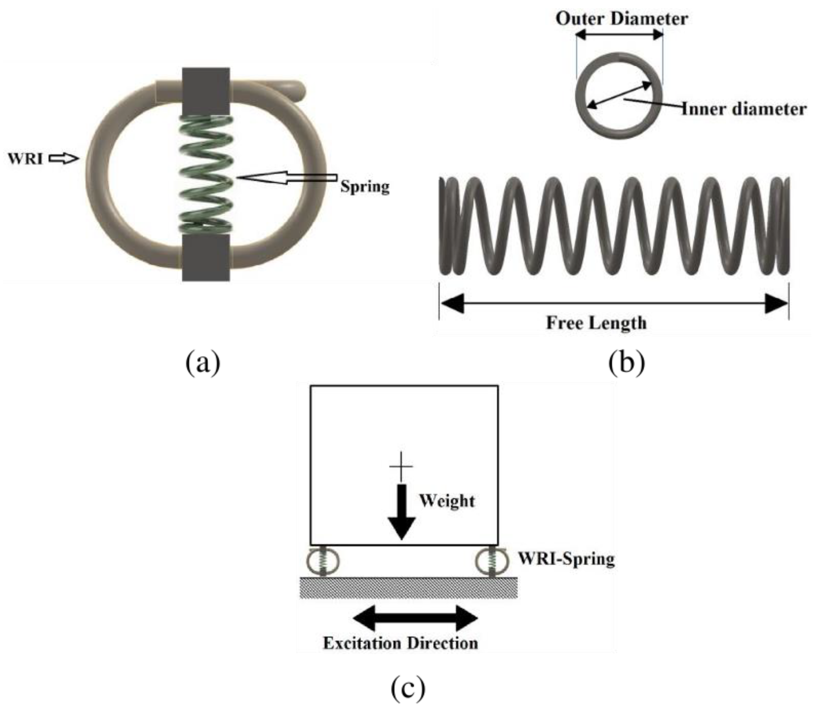
This section investigates the use of springs in conjunction with WRI (S-WRI) to improve its vertical load-carrying capacity. The configuration of the improved S-WRI (see
Figure 5 and
Figure 6) was investigated to determine the performance improvement. To that end, three S-WRIs were fabricated in the lab.
Table 2 shows the specifications of the springs, and
Table 3 reports the configurations of the S-WRIs fabricated by welding on the springs.
Figure 6 shows the S-WRI configurations. The primary reason behind making three sets of S-WRIs was to identify and verify the ability of the springs to provide similar benefits to all three cases. Hence, three WRIs, each having different wire rope diameters, were used to fabricate the S-WRIs. The spring was expected to improve the vertical loading carrying ability of the WRI; the loading in the vertical direction was performed to evaluate the stiffness of the S-WRI. The improved isolators were subjected to vertical monotonic loading using the same setup as the conventional WRI. Monotonic loading tests in the vertical and lateral directions assuming a small displacement range were performed for each S-WRI to identify the spring contribution to the stiffness of the original WRI. The test setup is shown in
Figure 7.
Table 4 reports the stiffness of each S-WRI and the stiffness ratios in both directions. It was found that the spring can improve the vertical stiffness of the WRI and simultaneously maintain the flexibility for lateral excitation. In addition, this observation was valid for all three cases. Hence, it can be concluded that the addition of springs inside a conventional WRI can improve the vertical stiffness of the WRI, making it better suited for applications that require both vertical and lateral stiffness. Furthermore, the results show that the spring acts in parallel configuration with the WRI to effectively support the system’s mass. Moreover, it can also be seen that the increased stiffness is achieved in the same geometrical size. Hence this design incorporation effectively improves the stiffness without a significant need for change in the higher dimensions.
The vertical stiffness of the S-WRI can be computed using the following equation:
where
is the vertical stiffness of the S-WRI configuration,
is the number of springs,
is the stiffness of the spring in the vertical direction, and
is the vertical stiffness ratio. Equation (1) can be used to design an S-WRI with the required stiffness to carry the weight of the equipment/machine. Of course, there is always the flexibility to add a different number of springs with other stiffness properties. This observation shows the easy-to-configure nature of the S-WRI to obtain the required stiffness property. Mainly, the parallel spring arrangements assist the WRI in its vertical load-carrying ability; in addition, the lateral stiffness is also increased.
6. Double Wire Rope Isolator: An Experimental Investigation
This section investigates a new design for wire rope isolators that enhances their stiffness and damping properties. This Double-WRI (D-WRI) design involves inserting a small WRI inside the space of a big WRI, as shown in
Figure 8, where “big” refers to the outer WRI and “small” refers to the inner WRI. The small WRI is placed inside the big WRI and depends on the geometric compatibility between the two WRIs. Three variations of the D-WRI were developed in the research lab. The big or outer WRIs used were isolators No. 3, 5, and 8 for each design and had different wire rope diameters. The WRI combinations were developed based on the available WRIs.
Meanwhile, for the S-WRI design, three WRIs were already available, and hence the geometrically compatible ones were merged with the remaining WRIs in stock. For isolators #3 and #5, two small WRIs, Sm.1 and Sm.2, were purchased to fabricate new D-WRIs. The isolators used in the D-WRI configurations are shown in
Table 5 and
Table 6.
The D-WRI design differs from the S-WRI design in that it uses two smaller WRIs instead of one large WRI. The D-WRI designs were developed to simultaneously improve the damping and stiffness of the big WRI by combining it with a smaller WRI. The advantages of both WRIs are combined in these configurations. They can be customized to fit any required stiffness and damping as per the application requirement within the available space.
Quasi-static cyclic loading tests were carried out to study the D-WRI characteristics. The experimental test setup is shown in
Figure 9. The two WRIs were joined by welding at their metal retainers to make them act unified in all directions. This design is flexible since several smaller WRIs can always be placed inside the bigger ones to achieve the desired stiffness and damping enhancement within the limited space dictated by the outer WRI. However, in the case of more than two WRIs, care should be taken to provide sufficient space between the WRIs so any hindering can be avoided from each other during displacement.
The cyclic loading tests were carried out to investigate how the WRIs act together.
Figure 10 shows the cyclic loading behavior of the D-WRI. The effective damping ratio and effective stiffness of the D-WRI were evaluated for various displacement amplitudes and the results are shown in
Table 7 and
Table 8. A comparative study was also carried out on the effective stiffness and effective damping ratio of the D-WRI with the single WRI (Big) to understand the enhancement from the equivalent height of the isolator. The effective damping ratio and effective stiffness were evaluated as per Balaji et al. [
18] and they are given by Equations (2) and (3), respectively.
where
is the hysteresis loop area, and
and
are the maximum and minimum forces, respectively.
and
are the maximum and minimum displacements, respectively.
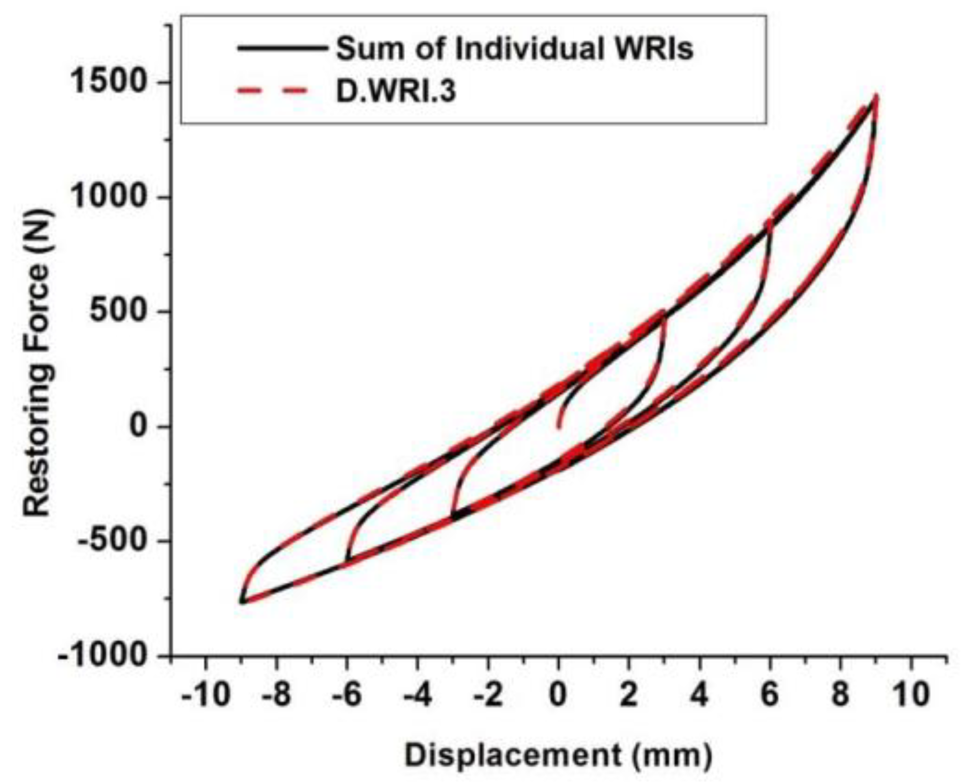
It can be observed that both stiffness and damping are improved in this D-WRI design. Suitable WRI combinations can be made as per the application requirements. This study shows that the hysteresis characteristics due to cyclic loading of the D-WRI can be given as the sum of the hysteresis curves of the individual WRIs (
Figure 11). Therefore, the improvement in this D-WRI design can be estimated using the individual hysteresis curves of the WRIs, provided they are also geometrically compatible. The results of the hysteresis show that the D-WRI has a parallel arrangement of both the WRIs that were combined in the D-WRI. Further, this configuration provides an increase in both stiffness and damping. The cyclic loading test results of
Figure 10 show the individual hysteresis characteristics, and when they are combined with D-WRI configurations, their behavior sums up together. This nature also provides a way to identify what combinations can be made for the required hysteresis behavior. However, in addition to the cyclic behavior requirements, the dimension compatibility also needs to be verified for design compatibility.
7. Summary and Conclusions
In the present study, monotonic and quasi-static cyclic loading tests were performed on conventional wire rope isolators and two variants to improve load-carrying capacity, stiffness, and damping. The tests were carried out in compression/tension and roll mode.
The first investigation on conventional wire rope isolators found that their stiffness significantly depends on the wire rope diameter. For instance, increasing the wire rope diameter from 9 mm to 15 mm increases the WRI stiffness by a factor of eight. Additionally, the stiffness of a wire rope isolator is affected by the coil width, height, and diameter of the wire rope. Widening the coil or decreasing the height decreases the stiffness, while increasing the height increases the stiffness, and hence a higher height-to-width ratio gives higher stiffness of a given diameter wire rope.
The number of turns in a wire rope isolator affects its stiffness, affecting the equipment’s stability. Therefore, a stiffer WRI should have a greater number of turns. WRIs are typically manufactured with an even number of turns to provide adequate stability.
The WRI is desirable because it is effective in all planes and any direction. A larger WRI has more lateral and vertical stiffness, while a smaller WRI has less lateral and less vertical stiffness.
The objectives of the second and third experimental investigations were proposed improvements to the conventional design of WRIs. These were deemed essential for applications in which the mass of the target structure/equipment is large or the space to insert bigger isolators is limited.
To achieve the second main objective of this study, we investigated the use of springs in conjunction with a WRI (S-WRI) experimentally to improve its vertical load-carrying capacity. Three sets of S-WRIs were fabricated and tested in the vertical and lateral directions. It was found that the addition of springs inside a conventional WRI can improve the vertical stiffness of the WRI, making it better suited for applications that require both vertical and lateral stiffness.
Another design was proposed to achieve the third main objective of this study. The design was called D-WRI and involved inserting a smaller WRI inside the space of a big WRI. This development aimed to improve the stiffness and damping of the big WRI simultaneously. The experimental investigation demonstrated that the D-WRI design is flexible in that it can be tailored to suit any required stiffness and damping and overcome any space limitations.
Furthermore, these quasi-static cyclic loading tests showed that the hysteresis characteristics of the D-WRI can be expressed as the sum of the hysteresis curves of the big (outer) and small (inner) WRIs, provided both WRIs are geometrically compatible. This configuration suggests that the improvement in the D-WRI can be estimated using the individual hysteresis curves of the WRIs. The scientific contribution of the present work is these configurations which can be beneficial in applications for heavy-mass equipment and limited space. Furthermore, the configurations proposed were studied for their behavior to support these applications. From this study, it can be observed that WRIs can be combined with other isolators to enhance the characteristics per the application requirements.
Author Contributions
Conceptualization, M.L. and M.E.R.; methodology, P.S.B.; software, P.S.B.; validation, M.L., P.S.B. and M.E.R.; formal analysis, M.L. and P.S.B.; investigation, M.L., P.S.B. and M.E.R.; resources, M.E.R.; writing—original draft, M.L. and P.S.B.; writing—review & editing, M.L. and M.E.R.; visualization, P.S.B.; supervision, M.L. and M.E.R.; project administration, M.E.R.; funding acquisition, M.L. and M.E.R. All authors have read and agreed to the published version of the manuscript.
Funding
This paper is based upon work supported by the Ministry of Higher Education (MOHE), Malaysia, under the ERGS grant scheme. The University of Sharjah provided partial support.
Institutional Review Board Statement
Not applicable.
Informed Consent Statement
Not applicable.
Data Availability Statement
The datasets used and analyzed during the current study are available from the corresponding author upon reasonable request.
Acknowledgments
This work has been supported by the Ministry of Higher Education of Malaysia. Partial support was provided by Curtin University Malaysia and the University of Sharjah. This support is highly appreciated.
Conflicts of Interest
The authors declare that they have no known competing financial interests or personal relationships that could have appeared to influence the work reported in this paper.
References
- Klembczyk, A.R. Introduction to Shock and Vibration Isolation and Damping Systems. Available online: https://www.taylordevices.com/wp-content/uploads/74-Introduction-to-Shock-and-Vibration.pdf (accessed on 25 April 2014).
- Simmons, R. Vibration isolation. ASHRAE J. 2007, 49, 30. [Google Scholar]
- Velinsky, S.A. Compressive Loading of Stiffened, Wire-Strand Based Structures. Mech. Based Des. Struct. Mach. 2004, 32, 101–113. [Google Scholar] [CrossRef]
- Velinsky, S.A. Design and Mechanics of Multi-Lay Wire Strands. J. Mech. Transm. Autom. Des. 1988, 110, 152–160. [Google Scholar] [CrossRef]
- Velinsky, S.A. On the Design of Wire Rope. J. Mech. Transm. Autom. Des. 1989, 111, 382–388. [Google Scholar] [CrossRef]
- Ni, Y.Q.; Ko, J.M.; Wong, C.W.; Zhan, S. Modelling and identification of a wire-cable vibration isolator via a cyclic loading test. Part 1: Experiments and model development. Proc. Inst. Mech. Eng. Part I J. Syst. Control Eng. 1999, 213, 163–172. [Google Scholar] [CrossRef]
- Ni, Y.Q.; Ko, J.M.; Wong, C.W.; Zhan, S. Modelling and identification of a wire-cable vibration isolator via a cyclic loading test. Part 2: Identification and response prediction. Proc. Inst. Mech. Eng. Part I J. Syst. Control Eng. 1999, 213, 173–182. [Google Scholar] [CrossRef]
- Tinker, M.; Cutchins, M. Damping phenomena in a wire rope vibration isolation system. J. Sound Vib. 1992, 157, 7–18. [Google Scholar] [CrossRef]
- Tse, P.; Lau, K.; Wong, W.; Reid, S. Spring stiffnesses of composite circular springs with extended flat contact surfaces under unidirectional line-loading and surface-loading configurations. Compos. Struct. 2002, 55, 367–386. [Google Scholar] [CrossRef]
- Selvaraj, B.P. An Analytical and Experimental Study on Wire Rope Isolators for Vibration Isolation of Equipment and Structures. Ph.D. Thesis, Curtin University, Perth, Australia, 2017.
- Demetriades, G.; Constantinou, M.; Reinhorn, A. Study of wire rope systems for seismic protection of equipment in buildings. Eng. Struct. 1993, 15, 321–334. [Google Scholar] [CrossRef]
- Wang, H.-X.; Gong, X.-S.; Pan, F.; Dang, X.-J. Experimental Investigations on the Dynamic Behaviour of O-Type Wire-Cable Vi-bration Isolators. Shock. Vib. 2015, 2015, 869325. [Google Scholar]
- Alessandri, S.; Giannini, R.; Paolacci, F.; Malena, M. Seismic retrofitting of an HV circuit breaker using base isolation with wire ropes. Part 1: Preliminary tests and analyses. Eng. Struct. 2015, 98, 251–262. [Google Scholar] [CrossRef]
- Leblouba, M.; Rahman, M.; Barakat, S. Behavior of polycal wire rope isolators subjected to large lateral deformations. Eng. Struct. 2019, 191, 117–128. [Google Scholar] [CrossRef]
- Lee, S.-J.; Truong, G.T.; Lee, J.-E.; Park, S.-H.; Choi, K.-K. Dynamic characteristics of combined isolation systems using rubber and wire isolators. Nucl. Eng. Technol. 2021, 54, 1071–1084. [Google Scholar] [CrossRef]
- Cen, B.; Lu, X.; Zhu, X. Research of numerical simulation method on vertical stiffness of polycal wire rope isolator. J. Mech. Sci. Technol. 2018, 32, 2541–2549. [Google Scholar] [CrossRef]
- Barbieri, N.; Barbieri, R.; da Silva, R.A.; Mannala, M.J.; Barbieri, L.D.S.V. Nonlinear dynamic analysis of wire-rope isolator and Stockbridge damper. Nonlinear Dyn. 2016, 86, 501–512. [Google Scholar] [CrossRef]
- Balaji, P.S.; Moussa, L.; Rahman, M.E.; Vuia, L.T. Experimental investigation on the hysteresis behavior of the wire rope isolators. J. Mech. Sci. Technol. 2015, 29, 1527–1536. [Google Scholar] [CrossRef]
- Balaji, P.S.; Moussa, L.; Rahman, M.E.; Ho, L.H. An analytical study on the static vertical stiffness of wire rope isolators. J. Mech. Sci. Technol. 2016, 30, 287–295. [Google Scholar] [CrossRef]
- Balaji, P.S.; Selvakumar, K.K. Applications of Nonlinearity in Passive Vibration Control: A Review. J. Vib. Eng. Technol. 2020, 9, 183–213. [Google Scholar] [CrossRef]
- Salvatore, A.; Carboni, B.; Chen, L.-Q.; Lacarbonara, W. Nonlinear dynamic response of a wire rope isolator: Experiment, identification and validation. Eng. Struct. 2021, 238, 112121. [Google Scholar] [CrossRef]
- Rashidi, S.; Ziaei-Rad, S. Experimental and numerical vibration analysis of wire rope isolators under quasi-static and dynamic loadings. Eng. Struct. 2017, 148, 328–339. [Google Scholar] [CrossRef]
- Vaiana, N.; Spizzuoco, M.; Serino, G. Wire rope isolators for seismically base-isolated lightweight structures: Experimental characterization and mathematical modeling. Eng. Struct. 2017, 140, 498–514. [Google Scholar] [CrossRef]
- Lu, Z.-Q.; Liu, W.-H.; Ding, H.; Chen, L.-Q. Energy Transfer of an Axially Loaded Beam with a Parallel-Coupled Nonlinear Vibration Isolator. J. Vib. Acoust. 2022, 144, 051009. [Google Scholar] [CrossRef]
- Leblouba, M.; Balaji, P.; Muhammad, E. Quasi-static cyclic behavior of wire rope isolators: Comprehensive experimental study and improved mathematical modeling. Heliyon 2022, 8, e10944. [Google Scholar] [CrossRef] [PubMed]
- Balaji, P.S.; Moussa, L.; Rahman, M.E.; Ho, L.H. Static lateral stiffness of wire rope isolators. Mech. -Based Des. Struct. Mach. 2016, 44, 462–475. [Google Scholar] [CrossRef]
- Shenton, H.W., III. Draft Guidelines for Prequalification and Prototype Testing of Seismic Isolation Systems. In Proceedings of the NISTIR 5359, March 1994; National Institute of Standards and Technology: Gaithersburg, MD, USA, 1996. [Google Scholar]
- Shenton, H.W.I. Guidelines for Pre-Qualification, Prototype and Quality Control Testing of Seismic Isolation Systems; National Institute of Standards and Technology: Gaithersburg, MD, USA, 1996. [CrossRef]
| Publisher’s Note: MDPI stays neutral with regard to jurisdictional claims in published maps and institutional affiliations. |
© 2022 by the authors. Licensee MDPI, Basel, Switzerland. This article is an open access article distributed under the terms and conditions of the Creative Commons Attribution (CC BY) license (https://creativecommons.org/licenses/by/4.0/).


