Article

Experimental Analysis of Surface Application of Fiber-Reinforced Polymer Composite on Shear Behavior of Masonry Walls Made of Autoclaved Concrete Blocks

Department of Civil Engineering, Silesian University of Technology, Akademicka 5 St., 44-100 Gliwice, Poland
Buildings 2022, 12(12), 2208; https://doi.org/10.3390/buildings12122208
Submission received: 10 November 2022 / Revised: 2 December 2022 / Accepted: 8 December 2022 / Published: 13 December 2022
(This article belongs to the Special Issue Fiber Reinforced Polymer (FRP) Composites for Construction)

Abstract

:
This paper presents the results of an experimental study of the shear behavior of masonry walls made of aero autoclaved concrete (AAC) blocks strengthened by externally bonded fiber-reinforced polymer (FRP) composites. Fifteen small wall specimens were constructed and tested in a diagonal compression scheme. Two types of composite materials—carbon- and glass-reinforced polymers—were arranged in two configurations of vertical strips, adopted to the location of the unfilled head joints. The effect of the strengthening location and strengthening materials on changes in the strength and deformability parameters are discussed and the failure process of unstrengthened walls is also presented. The placement of the composite on unfilled head joints proved to be a better solution. Carbon-fiber-reinforced polymer (CFRP) strips provided a threefold increase in stiffness, a 48% increase in load-bearing capacity and a high level of ductility in the post-cracking phase. Glass-fiber-reinforced polymer (GFRP) strips offered a 56% increase in load-bearing capacity but did not change the stiffness of the masonry and provided relatively little ductility. Placing the composite between unfilled joints was only reasonable for CFRP composites, providing a 35% increase in load-bearing capacity but with negligible ductility of the masonry.

1. Introduction

Aero autoclaved concrete blocks (AAC) are commonly used to erect load-bearing walls in low-rise buildings, as well as the infill walls in a frame system [1,2]. The popularity of this material is mainly due to its very good physical parameters, particularly its excellent thermal insulation properties, relatively high fire resistance and low density (resulting in the weight of the elements made of AAC) [3,4]. The second positive aspect is the widespread workability and very large variety of available products. This material can be easily processed (cutting on site), transported, and it provides a fast and simple technique for erecting walls with thin horizontal joints and unfilled vertical joints (a huge advantage in terms of the time investment required). Unfortunately, this technology makes walls made of AAC blocks sensitive to shear forces.
Enhancement of the shear parameters of existing masonry walls can be carried out through the application of externally bonded nonmetallic materials, such as fiber-reinforced polymer (FRP) composites [5,6,7,8]. This material has long been used to effectively strengthen reinforced concrete elements [9,10,11,12], primarily due to its very good strength parameters and the corrosion resistance of the composites [13,14,15]. The FRP system uses laminates or fabrics reinforced with high-strength carbon, glass or other nonmetallic fibers. These materials are glued to the surface of the elements using systemic epoxy adhesives.
There are numerous studies available in the literature describing the high effectiveness of this method in terms of increasing the load-bearing capacity of the masonry walls made of ceramic or stone elements subjected to static in-plane shearing [16,17]. However, the epoxy resins used here (adhesive layer) significantly deteriorate the diffusivity of such strengthened walls. Therefore, in order to ensure at least a partial diffusion of water vapor from the strengthened masonry elements, the composite is arranged in one-way strips, a grid setup or diagonal configuration (in the direction of the tensile stresses in the wall being sheared). An important finding of the study conducted by Valluzi et al. [18] was that the diagonal configuration of the FRP strips is more efficient, in terms of shear capacity, than the grid setup; however, the grid arrangement offers a better stress redistribution. Similar conclusions were reached by Kalali and Kabir [19], and Bui et al. [20]. Santa-Maria et al. [21] indicated that horizontally placed CFRP strips were more effective in crack propagation than a diagonal arrangement, which, in contrast, increased energy dissipation. It has been proven that the less stiff FRP material (with lower E-modulus) appeared to be more effective in terms of the ultimate strength and stiffness increase in the masonry panels [18,22]. Luccioni and Rougier [23] compared the impact of different CFRP configurations in retrofitted and repaired solid clay walls, indicating that the strip arrangement of FRP in repairing techniques presents the same benefits as FRP retrofitting. Noteworthy are the studies of two research teams, Kwiecień et al. [24,25] and Umair et al. [26], which successfully attempted to eliminate the major disadvantage of the FRP solution, namely the delamination of the strengthening due to the low stiffness of the adhesive and the composite itself, compared to the relatively highly deformable masonry substrate. In the study [24], flexible polymer joints were used to achieve more ductile behavior of the strengthened structures with a simultaneous increase in their load-bearing capacity. Umair et al. [26] proposed the use of a combination of different FRP materials (CFRP, AFRP and GFRP strips) and PP bands (polypropylene), which are characterized by a high tensile failure strain. Such a combination of materials has not only increased the initial strength and deformation capacity, but also the residual strength of masonry wall panels. The positive effects of the PP band are also presented by Sathiparan and Meguro [27].
AAC blocks are unusual masonry materials that are not very well recognized in research. There are very few studies reporting the influence of FRP strengthening system on the load-bearing capacity of such walls. The first experiments were initiated by a team led by Kubica [28,29]. Their studies indicated the positive influence of strengthening in the form of vertical FRP strips, providing a significant (30–75%) increase in load-bearing capacity and deformability of the walls, depending on the composite used. Saad et al. [30] presented the results of testing two walls made of AAC blocks and subjected to lateral static loads. The walls were strengthened in a single grid configuration (vertical and horizontal strips) using CFRP fabrics, which wrapped the entire wall. An almost two-and-a-half fold increase in the load capacity and stiffness of the strengthened walls was indicated. Interesting conclusions from explosion tests, which were conducted on 10 cm thick panels made of AAC, were presented in the work of the team lead by Wang [31]. The panels were strengthened using CFRP sheets. Such operations made it possible to achieve an increase in mechanical properties and excellent anti-blast resistance of strengthened panels. In addition to these singular studies, it is also possible to find some analysis of the impact of full-surface strengthening applications using various types of glass [32] and basalt [33] meshes, systemic PBO materials [34] or highly ductile concrete cover [35,36]. However, this research involves a different type of wall strengthening based on TRM systems.
Taking into account the results of the studies shown in [28,29] and the conclusions derived from the work by [18,22], this paper presents a detailed analysis of the influence of the vertical strips made of CFRP and GFRP materials on the behavior of small masonry walls. The most feasible way of laying the FRP material was chosen, i.e., vertical strips covering (type a) or not covering (type b) the unfilled head joints. The specimens were tested in a diagonal compression scheme according to recommendation in [37]. The first part of the paper presents the results of the laboratory tests and analyzes the behavior of the walls in the pseudo-elastic phase (until full load-bearing capacity is reached) and post-cracking phase, depending on the location and type of the strengthening material used. The second part includes discussion of the failure process of the unstrengthened and selected strengthened walls and comparative analysis of the impact of strengthening mode, with respect to the unstrengthened walls. Such a detailed qualitative analysis of the issue and describing the failure process of unstrengthened and strengthened walls made of AAC blocks has not been performed before. The information provided in the cited studies is fragmentary and does not allow for a proper recognition of the changes that occur in walls strengthened using this method.
The investigation presented in this paper is the first part of a large research program to identify an effective method for enhancing the shear parameters of AAC block walls and to develop a simple calculation method that takes into account the increase in load-bearing capacity and deformability of such walls.

2. Materials and Testing Procedure

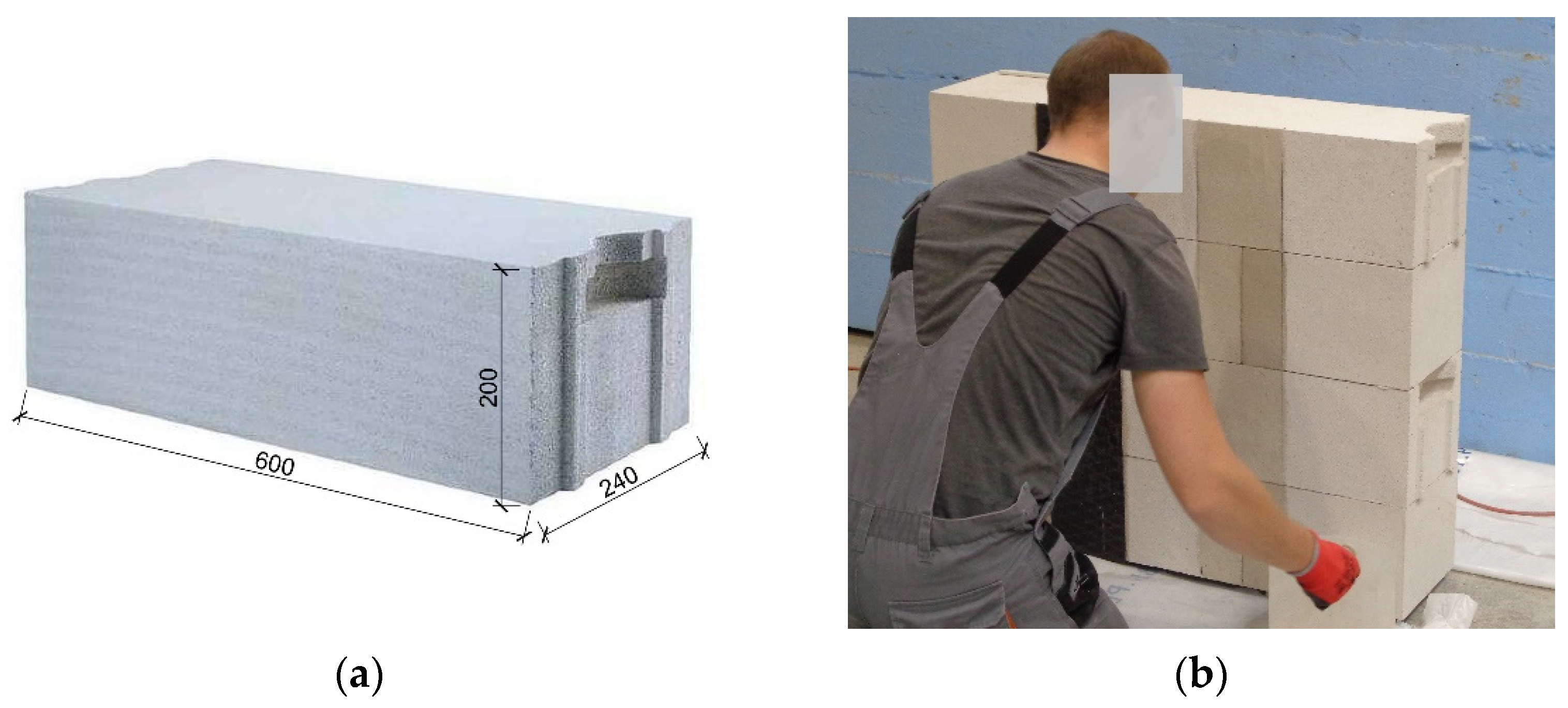
2.1. Characteristic of the Masonry Walls

Laboratory tests were carried out on small masonry walls according to the recommendations in Rilem Lumb 6 [37]. The dimensions of the elements were 805 × 900 mm, with a thickness of 240 mm. Each wall consisted of four rows of one and a half AAC blocks. The dimensions of a single block were 200 × 600 × 240 mm. The walls were made using the typical erecting technique for AAC blocks, i.e., with thin bed joints (up to 3 mm) and unfilled head joints. Figure 1 presents the AAC block and the preparation of the specimens.
The compressive strength of AAC blocks was determined according to EN 772-1:2000 [38]. The normalized mean compressive strength of masonry units are specified in Table 1. The standard deviation is given in brackets.
The mortar used for the thin bed joints was tested in accordance with the recommendations in EN 1015-11 [39]. According to very limited data obtained from the mortar manufacturer, the base of the mortar is Portland cement, dust from the Portland cement production and calcium hydroxide, with their mass content below 40%, 1% and 3%, respectively. The flexural strength of the mortar was determined on typical beams of 40 × 40 × 160 mm, and then the compressive strength of the beam halves was determined. The strength parameters are specified in Table 1.

2.2. Characteristics of the FRP Strengthening

The walls were strengthened with two types of FRP composite, produced by S&P Company. The carbon-fibers-reinforced polymer (CFRP) was C-Sheet 240, with a weight of fibers 200 g/m2, and the glass-fiber-reinforced polymer (GFRP) used was G-Sheet AR 90/10. The sheets were glued to the masonry surface using two-component epoxy resin dedicated to a given strengthening system—S&P Resin 55. Two types of FRP configuration were adopted: (a) the FRP strips held together the unfilled vertical joints and (b) the strips were placed in the areas between the unfilled vertical joints. The strengthening arrangement is shown in Figure 2. In the case of the carbon sheets, the strengthening strips were 150 mm wide, while the glass sheets were 200 mm wide. The FRP strengthening was made on both sides of the wall. The parameters of the sheets and the epoxy—according to the manufacturer’s data—are summarized in Table 2.

2.3. Experimental Program

In total, 15 single ACC walls were made and tested. The experimental program was divided into three main groups: unstrengthened elements, wallets strengthened using CFRP sheets and GFRP sheets. In each series, three elements were tested and a summary of all the tested wallets is given in Table 3.

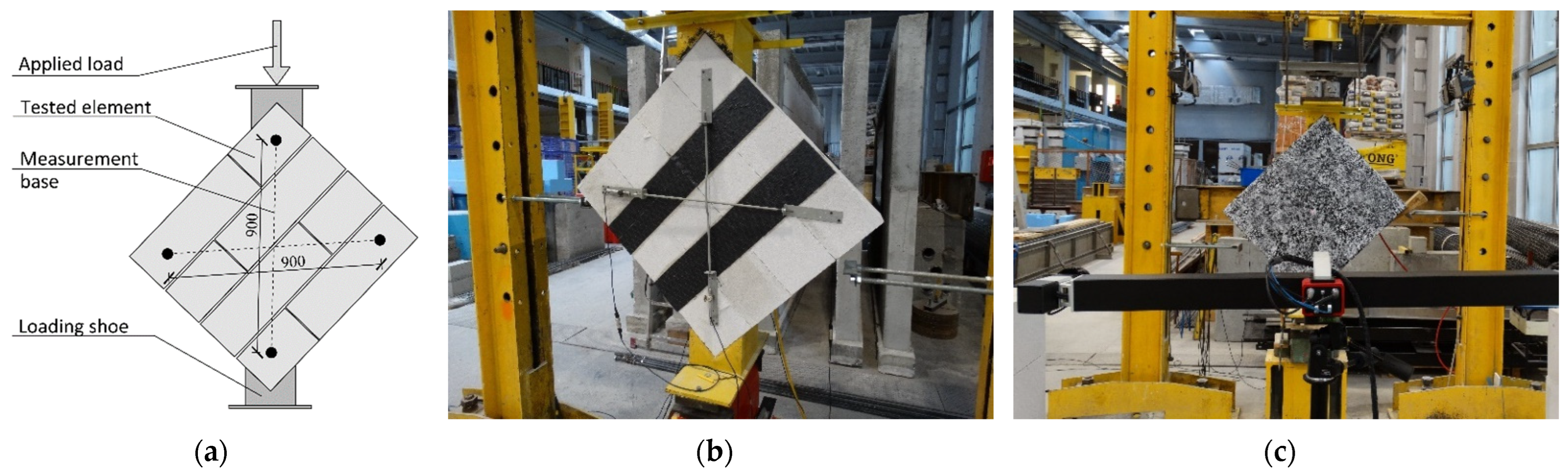
2.4. Testing Protocol

The walls were tested in a diagonal tension scheme according to the RILEM Lumb 6 [37] standard. The loading was applied using a manually activated hydraulic jack, placed on the upper edge of the panel. The speed load was approximately 0.15 kN/s.
During the test, the applied load and the diagonal displacements were measured and recorded by two linear variable displacement transducers (LVDT) on each side. The base measurement of the LVDT was 900 mm. In two of the models, one unstrengthened and one from the Y-CFRP-a series, an optical measurement of the displacement of the wall surface was performed using the ARAMIS measurement system. Figure 3 shows the test setup, model with the traditional measurement system (inductive gauges) and the Y-CFRP-a series model with optical measurement, which were prepared for testing.

2.5. Analyzed Strength and Deformation Parameters

2.5.1. Shear Strength

Traditionally, diagonal compression testing of masonry walls is used to determine the tensile strength of the elements, which results in the failure mode—diagonal cracking. Such an assumption is made by assuming that the panel starts to collapse at its center when the principal tensile stress attains its maximum value. Therefore, the strength parameter determines the principal tensile stress in the center of the panel, assuming its isotropic elastic properties.
The strength parameter is calculated as:
S d t = 0.707 P i A n
where Pi is the load value and An is the net area of the panel section determined using all dimensions of the masonry wall (h—height, l—length, t—thickness) as:
A n = l + h 2 · t

2.5.2. Shear Deformation Parameters

In addition to determining the strength, the deformation analysis is important for defining the deformation capacity of the panels. Based on the measurements of the elongation along the diagonals, the angular strain (shear strain) is calculated as:
γ = Δ V + Δ H l g
where ΔV is the vertical shortening, ΔH is the horizontal lengthening and lg is the gauge length equal to 900 mm. To improve readability, the stress–strain relationship diagrams were made independently for each type of strengthened wall; an identical scale was used for easier comparison.
The displacements of the wall in a vertical (compression) and horizontal (tensile) direction are also presented.
An important parameter that describes the stiffness of the masonry in the elastic phase is the shear modulus (G). The G modulus is defined as the secant modulus between 10 and 40% of the maximum shear stress:
G = σ 0.4 σ i γ 0.4 γ i
where σ0.4 and γ0.4 are the stress and strain at 40% of the maximum load, respectively. The initial stress and strain (σi and γi) were taken at a load level of 10% of the maximum diagonal load [40].
In many cases of the analyzed strengthened walls [20,41], the first cracks were followed by a phase of so-called ‘pseudo-ductile’ behavior. The pseudo-ductility coefficient (μd) best characterizes this phase of the structure’s operation. It describes the behavior of the wall in the post-elastic or post-peak phase. This coefficient is a ratio between the ultimate and elastic strain. The ultimate strain corresponds to the largest strain experienced during the test or, in the case of ambiguous identification of the moment of damage, the strain at a level of shear stress 20% below the peak, if the stress–strain diagram continues with a descending branch [41]. The definition of elastic strain (sometimes called cracking or yielding strain) was adopted, depending on the behavior of the masonry in the elastic phase. The elastic strain can be defined differently [41]: at the bend-over point where the stress–strain curve tends to be flat (yielding strain) or when the shear strain amounted to 70% or 75% of the peak load. In this paper, the ultimate strain (γu) corresponds to a strain value at a level of shear stress 20% below the maximum shear stress (or, if the failure occurs faster, at the ultimate load); the elastic strain (γcr) is taken at the moment when the first crack appears.
μ d = γ u γ c r

3. Results

It should be emphasized that the behavior and mode of failure of the tested walls are related to the adopted method of testing (diagonal compression) and do not fully reflect the work of the actual wall. The test stand for determining the tensile strength of a masonry wall in a diagonal compression scheme does not limit the possibility of displacement of the wall in the plane, which, in the actual structure, is ensured by further wall fragments or perpendicular walls. Additionally, the specimens are rotated with no contact to the ground. This is most evident in unstrengthened walls, as their failure mode differs from the actual mode.

3.1. Unstrengthened Wallets

In unstrengthened elements (Y-US) tested under diagonal compression, only one phase was distinguished—up until the cracking. The appearance of the crack was identified in a state of complete damage to the tested models. Therefore, the failure was characterized by one wide open crack with an almost diagonal orientation. No previous cracking was observed and the damage itself appeared suddenly and proceeded rapidly. The element split into two independent pieces (Figure 4a,b). The crack runs through unfilled joints and through masonry elements. It can also be seen that the bond capacity of the thin joint is insufficient as, each time, there was a detachment of the masonry elements in the plane of their horizontal connection.
The characteristics of the tested models were determined by the stress–strain relationship, which was linear in each case, with a proportional increase in stress as a function of the strain. So, the elements exhibited pseudo-elastic behavior, ending with the brittle failure of the wall. The stress–strain relationships of unstrengthened walls are shown on the graphs, along with the characteristics of the strengthened masonry walls, which allow a better assessment of the impact of strengthening.
Table 4 summarizes the values of the ultimate load (which is both the cracking load and the load-bearing capacity of the wall), the recalculated stresses, the strains and the shear modulus. The table does not include a pseudo-ductile coefficient, as the unstrengthened walls did not exhibit a ductile stage.

3.2. Walletes Strengthened Using FRP Materials

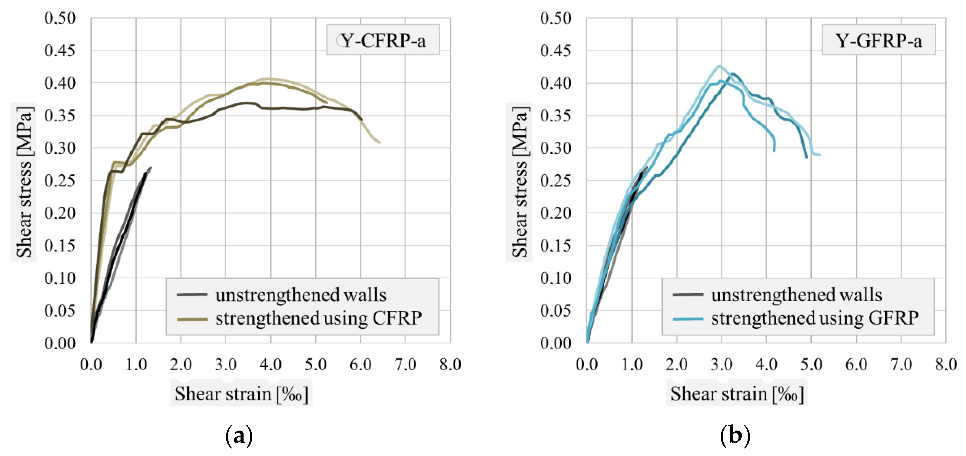
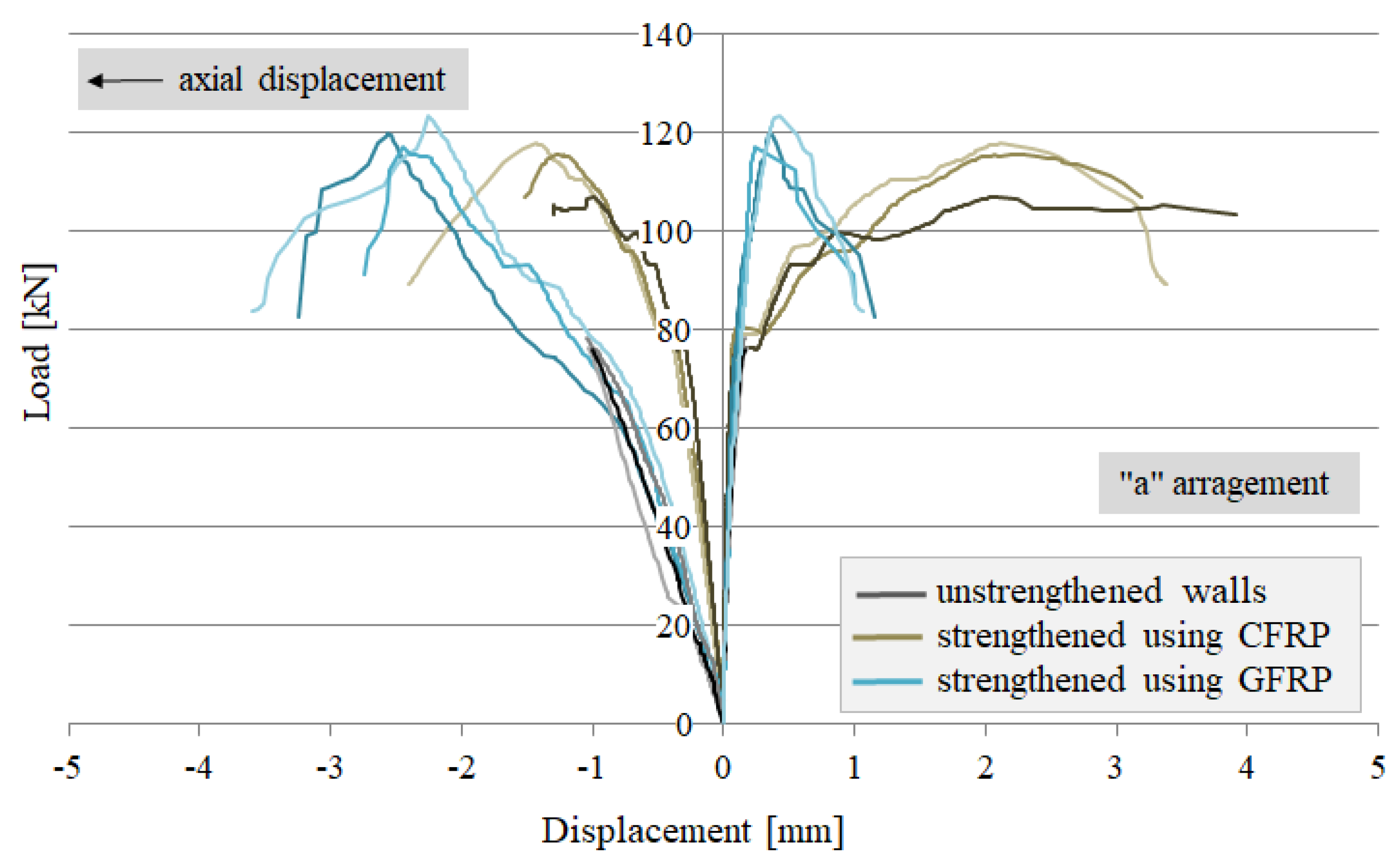
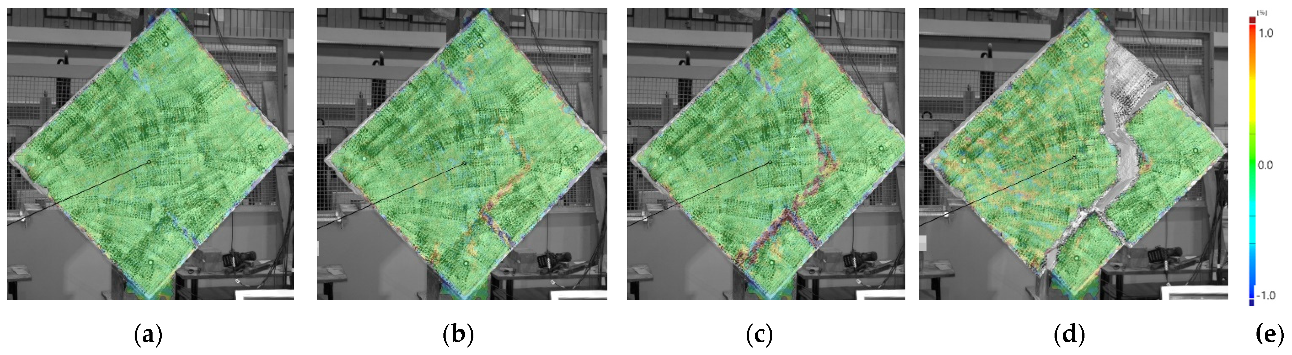
3.2.1. Characterization of Walls Strengthened in Configuration ‘a’

Walls strengthened using FRP strips covering unfilled head joints (configuration ‘a’) behaved similarly, regardless of the strengthening material used. Three phases of the element’s operation can be distinguished: the period up until the cracking (phase I), reaching full load-bearing capacity (phase II) and the final damage (phase III). These phases are clearly visible in the stress–strain relationship shown in Figure 5a,b. Figure 6 shows the build-up of the displacement in the direction of the main stresses (compression—axial direction and tension—horizontal direction) as a function of the applied load. In addition, Table 5 summarizes the shear stress values that correspond to the characteristic points, namely: cracking, load-bearing capacity and ultimate damage. Table 6 lists the deformation parameters of the strengthened walls.
In the first phase, the elements exhibited a pseudo-elastic behavior that ended in cracking. Within this range, the modulus of elasticity was determined. It can be seen that the CFRP sheets provided much higher wall stiffness (2.5 times higher than GFRP sheets) which is related to a significant reduction in structural deformation at cracking. The strain of the walls of series Y-CFRP-a was only 0.517‰, while the cracking strain of the walls strengthened with GFRP strips was over 80% higher. A positive aspect of the use of CFRP sheets—in comparison with the application of GFRP sheets—was also the increase in cracking forces, which led to extension of the uncracked condition.
The second phase, ending in reaching full load-bearing capacity, varied depending on the material used. Carbon sheets provided a certain level of ductility to the structure; the deformation increased much faster than the loads. Therefore, it can be considered that the structure exhibited elasto-plastic behavior, which is confirmed by the high pseudo-ductility coefficient (Table 6). The GFRP sheets prevented the uncontrollable growth of deformation in the structure (the AAC blocks were gradually moving apart in the area of the unfilled joints) and, therefore, we do not observe the ductility effect. The value of the pseudo-ductility coefficient is smaller than 5, which confirmed the above. Eventually, a similar load-bearing capacity was obtained in both test series, with a slight advantage in favor of glass sheets. The GFRP sheets also provided less deformation at maximum force, but it was only 15% less.
In both configurations, the FRP materials provided the post-peak phase, i.e., the post-failure capacity. Both graphs (Figure 5a,b) show a descending branch of the curves.

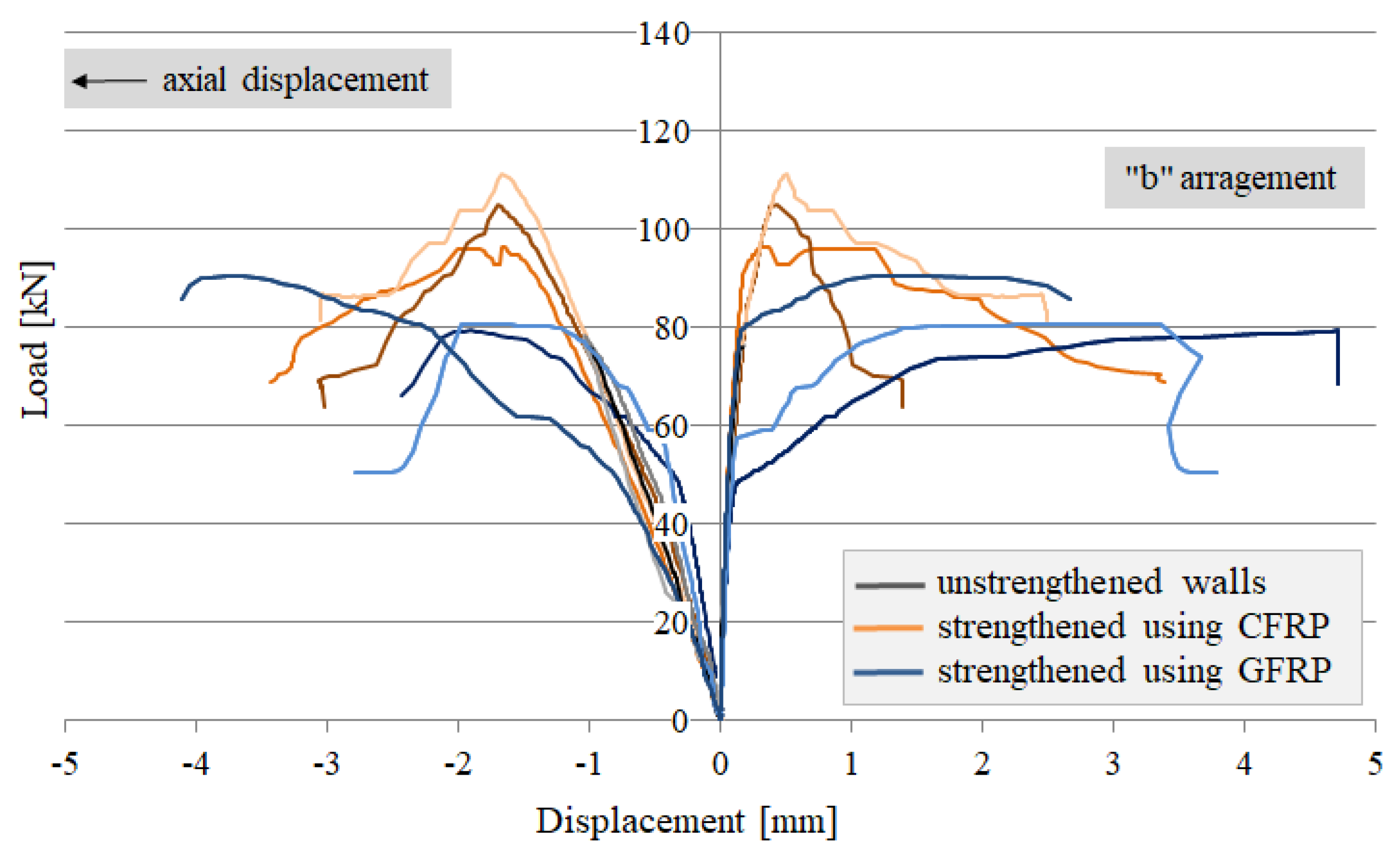
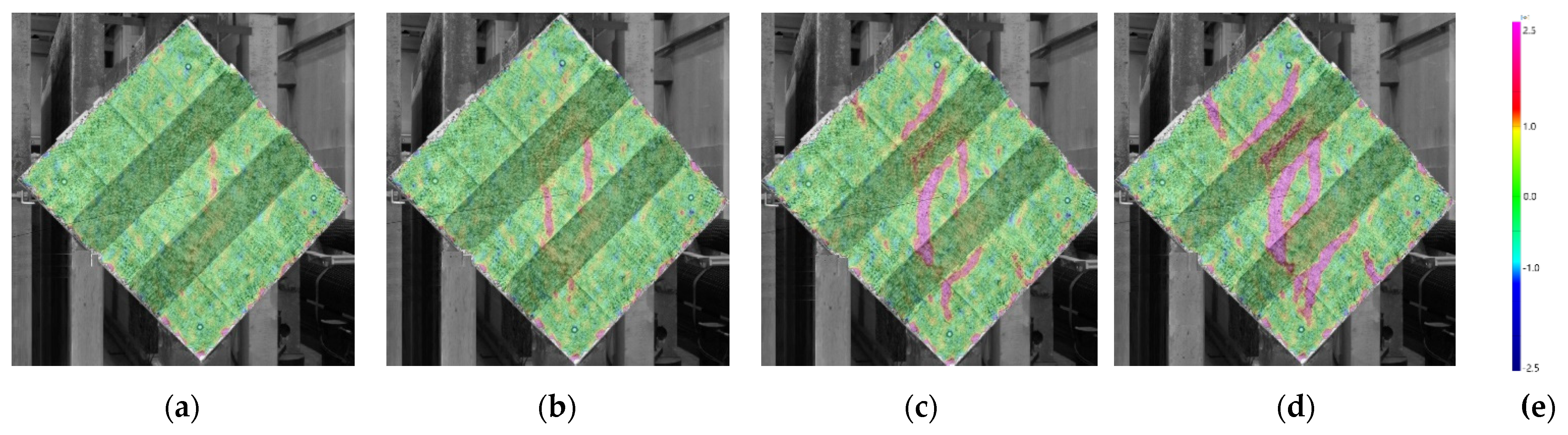
3.2.2. Characterization of Walls Strengthened in Configuration ‘b’

The application of the FRP sheets in the areas between unfilled head joints (configuration ‘b’) significantly changed the behavior of the elements, depending on the type of strengthening material. Figure 6 shows the successive work phases of the walls strengthened with CFRP (Figure 7a) and GFRP (Figure 7b) composites. Table 7 and Table 8 contain the relevant quantities (force, stress, strain, shear modulus and coefficient) determined at characteristic points—cracking, load-bearing capacity and failure.
The use of CFRP sheets resulted in a significant increase in cracking forces—which should be considered to be positive—but the appearance of the cracks was equivalent to reaching the full load-bearing capacity of the walls. Up to this point, the walls exhibited pseudo-elastic behavior; the elasto-plastic phase was not recorded here. The stiffness of the walls did not change, compared to the unstrengthened walls. In contrast, the lack of stabilization of unfilled joints and the use of GFRP sheets caused a significant acceleration of the cracking; the cracking force was twice as small as in the walls of the Y-CFRP-b series. In the pseudo-elastic phase observed in these walls, a highly variable stiffness modulus was noted. The cracking was followed by a process of rapid strain increase, accompanied by a minimal increase in bearing capacity (Figure 7b)—the clear ductile phase appeared.
In this strengthening configuration, the load-bearing capacity of elements from the Y-GFRP-b series was almost identical to the unstrengthened elements, while the use of CFRP sheets provided 25% higher load-bearing capacity than GFRP sheets and allowed for a significant reduction in strain at this point. The average deformation (shear strain) of the walls with CFRP was 2.657‰, while it was as high as 6.205‰ when GFRP sheets were used.
Generally, the post-peak phase was only observed in the walls strengthened with CFRP sheets. However, due to a relatively fast decrease in force in this phase and high cracking force, the value of the pseudo-ductile coefficient—determined for a 20% decrease in maximum force—was very small (less than 2, see Figure 8). In walls from the Y-GFRP-b series, no post-peak phase was observed but the walls were characterized by very high pseudo-ductility coefficients (Figure 8). However, it should be kept in mind that the load-bearing capacity of these walls was achieved just before the damage was slightly higher than that of unreinforced walls. Thus, the high level of safety of the masonry cannot be analyzed here, since its plasticity occurs at very low forces.

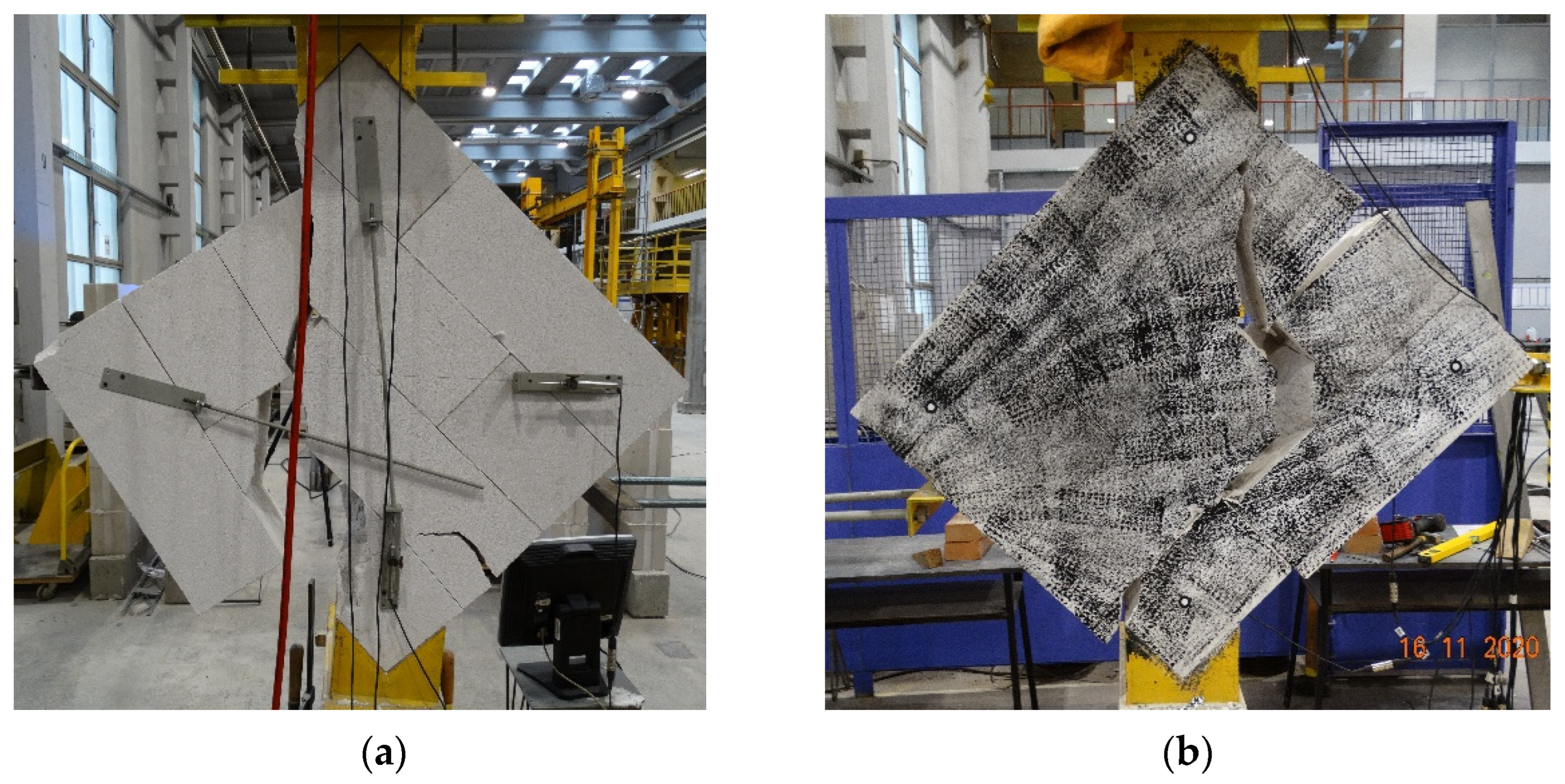
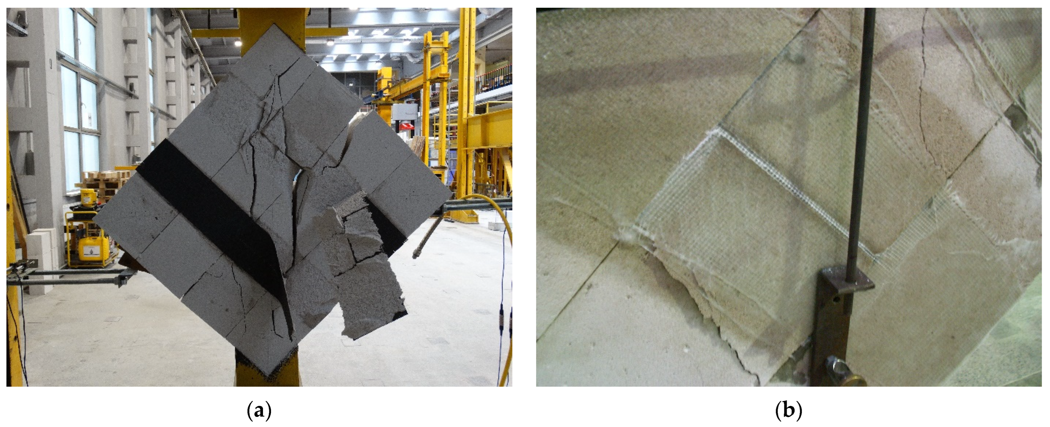
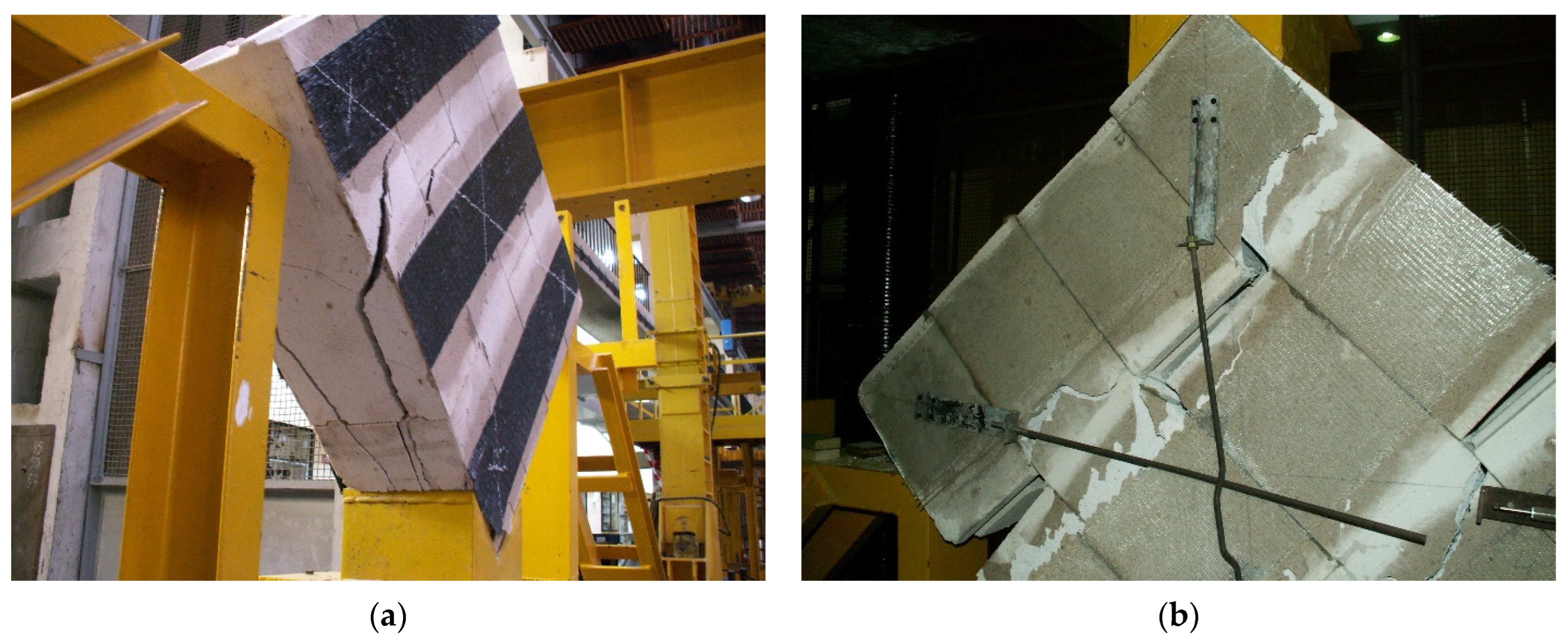
3.2.3. Failure Mode of Strengthened Walls

The final failure pattern of the walls with FRP strips glued on unfilled joints (configuration ‘a’) was the delamination of the strengthening materials from the masonry surface (Figure 9a,b). However, the precursory phenomenon of the delamination was different. In the case of the CFRP sheets, there was diagonal cracking of the masonry panels; then, delamination of the composite occurred due to the gradual widening of the cracks. Figure 9a clearly shows diagonal cracks running through the masonry and a detached part of the CFRP sheet (along with pieces of the masonry element). The intensity of the damage was very large and the walls were destroyed in their entirety. In the case of GFRP sheets, the deformation of the unfilled head joints took place, which led to ‘tensioning’ of the composite. Finally, through the use of a rigid epoxy adhesive, the outer layer of the masonry block was cut almost on the plane of the wall (delamination). Figure 9b shows a widened vertical joint, as well as the delamination of the GFRP sheets nearby.
The application of the strengthening between unfilled joints resulted in a different failure pattern, depending on the type of FRP material. The masonry with CFRP strips did not show diagonal failure; almost no cracks were observed on the masonry surface (Figure 10a). The damage occurred due to the separation of larger pieces of masonry—cracks in the masonry plane—along with the composite adhered to them. In the walls of Y-GFRP-b series, the excessive deformation of the unfilled head joints is clearly visible (Figure 10b). This led to the cracks in the planes of the vertical joints and led to the element breaking into vertical fragments, separated by strengthened pieces.

4. Discussion

4.1. Failure Initiation and Analysis

The use of an optical strain measurement system made it possible to determine the points initiating the failure of the unstrengthened masonry walls. Due to the unexpected and sudden damage to this type of specimen, it was not possible to capture the failure process with the naked eye. Figure 11 shows the successive steps in the process of strain growth and strain concentration. It is clearly visible that, in the initial phase of loading (about 50% of the maximum force), the strains increase in the areas of unfilled head joints (blue zone in Figure 11a). Subsequently, the widening of the head joints initiated the loss of adhesion within the thin bed joints, leading to a sudden growth of deformation in this area (Figure 11b). Thus, a strong strain concentration is observed at the crossing of these two joints (Figure 11c) and this is the point of masonry damage (Figure 11d).
As described in Section 3.2.3, the use of strengthening influenced the masonry failure; the type of strengthening material was crucial. Strengthening with CFRP sheets—regardless of their arrangement—eliminated the strain concentration in the joints (initially, unfilled joints and, then, thin joints), making the masonry become a more homogeneous and uniform material. This is evident when observing the surface deformation of the Y-CFRP-a series element, where an optical strain measurement system was used. Figure 12 shows the process of strain growth in the element with CFRP strips in configuration ‘a’. Figure 12a shows the location of the first strain concentration, which occurred at the force, causing cracking/failure of the unstrengthened walls (about 78 kN). There is no noticeable strain increase within the unfilled joins and thin bed joints. With successive loading, the diagonal character of the areas with intense color (the growth of the deformation) become more and more pronounced (Figure 12b). The places where delamination of the CFRP material begins also become clear (Figure 12c). At this level (about 95% of the maximum force), only a slight increase in deformation in the unfilled joint can be seen noticed. However, the deformation values are much smaller than in the other areas. Figure 12d shows the masonry just before failure, where the areas of the highest strain concentration, and, therefore, damage, are visible.
In the case of the application of a much more deformable strengthening material (GFRP sheets), an excessive deformation of the unfilled joints was not avoided. However, the strengthening location prevented—in different ranges—the masonry from very rapid damage or from falling apart, which was observed in the case of unstrengthened elements.

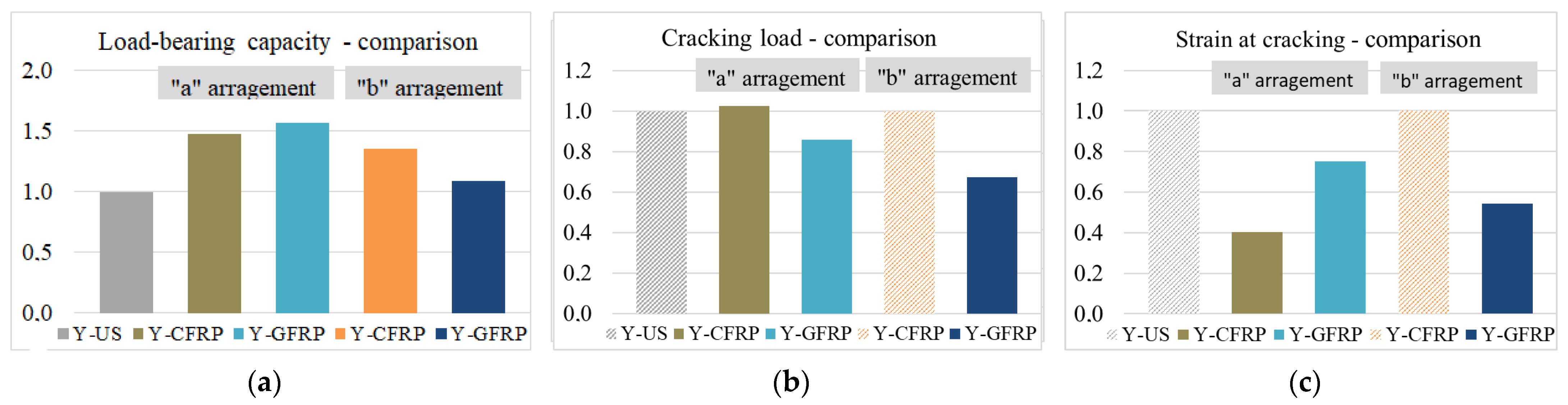
4.2. Comparison Analysis

A quantitative comparison of the behavior of the strengthened walls was made by summarizing the significant values for all the series tested. Figure 13a–c show the relative increases in load capacity, cracking load and strain at cracking, respectively, in accordance with the unstrengthened walls (value = 1.00). The dashed pattern denotes elements in which the appearance of the first cracks was equivalent to full load-bearing capacity. Figure 14a,b show the values of shear modulus and pseudo-ductility coefficient, respectively. In Figure 14b the dashed pattern refers to the average value, which is debatable due to the very large discrepancies in the partial results.
The strengthening made using CFRP strips in configuration ‘a’ was found to be the most effective solution. The strengthening combination provided a high level of cracking force, a significant increase in stiffness, an almost 50% increase in load-bearing and a high ductile coefficient (very desirable in terms of the occurrence of dynamic actions). This type of strengthening eliminated an important drawback of the technology of erecting these walls (unfilled joints initiate the failure process) by ensuring the uniformity of the structure. The application of CFRP sheets in the areas between the unfilled joints also has a positive effect, however, significantly smaller. This strengthening is characterized by the smallest load-bearing capacity, pseudo-ductility coefficient and the fact that the appearance of cracking is equivalent to reaching the load-bearing capacity of the wall results in a negligible safety reserve in the post-cracking phase.
The GFRP sheets in configuration ‘a’ offered high load-bearing capacities; however, they did not provide a clear elasto-plastic phase, nor a sufficient level of ductility. The use of GFRP outside of unfilled joints turned out to be completely ineffective. This solution results in the fast cracking and a negligible increase in the load-bearing capacity. The panels exhibit ductile behavior, which indicates a failure process; however, all this takes place at relatively low loads (equal to the failure loads of unreinforced masonry) and very high deformation of the structure.
Obtaining better characteristics of masonry walls by using CFRP materials (instead of GFRP) is the opposite of the trend presented in the literature [18,22]. This phenomenon is due to the specification of the masonry walls, i.e., relatively large masonry units and atypical erection technology. Excessive deformation of the unfilled joints, which leads to the insufficient adhesion in thin joints, is responsible for the failure of the unstrengthened walls. The stiff composite limits the excessive separation of unfilled joints (in configurations ‘a’), significantly reducing the deformation when the first cracks appear (Figure 13c) and changing the distribution of cracks in the entire structure (Figure 12b).

5. Conclusions

The enhancement of the shear capacity of masonry walls is a necessary action wherever there are horizontal forces acting in the plane of the wall. A good example of this is areas exposed to the seismic actions or influence of mining operations. The problem is particularly important for walls made with unfilled head joints, including those made of AAC blocks, which have poor resistance to any shear forces.
In the literature, a number of examples of shear strengthening of walls using FRP materials can be found but mostly concerning walls (mainly ceramic) with all solid joints. On this basis, it was deemed worthwhile to study the surface strengthening of very popular AAC block walls in an attempt to select an effective strengthening system due to the materials used for this purpose. Therefore, a series of laboratory tests on small walls made of AAC blocks were performed in accordance with the recommendations of the standard [37]. This assumed them to be representative in terms of recognition of the issue. Based on the results of the laboratory tests, the following conclusions were made:
(1)
Analysis of the failure process in unstrengthened AAC masonry walls identified the critical points in the structure that initiate its final damage. These were unfilled head joints in which displacement of adjacent blocks occurred, resulting in overloading and subsequent destruction of the bed joints.
(2)
The application of CFRP sheets—regardless of their arrangement—changed the behavior of the masonry, which now worked as an almost homogeneous material. There was no deformation of the unfilled head joints. This provided positive effects, in terms of the crack delay, an increase in stiffness (more than two times higher than in the unstrengthened walls) and load-bearing capacity by 48% (with strips on unfilled joints) and 35% (with strips between the vertical joints). In the first case, the failure was in the form of diagonal cracking with a final sheet detachment; in the second case, there was a splitting in the wall plane of the entire specimens.
(3)
The use of much deformable GFRP sheets did not avoid the excessive deformation of the unfilled head joints. At the same time, with strips applied to unfilled joints, the load capacity of the specimens increased by 56% and, in the case of GFRP strips located between head joints, by only 9%. In the first case, there was delamination of the sheets after large mutual displacements of the blocks. In the second, there were pronounced cracks parallel to the sheets (in the line of the head joints).
(4)
The advantage of application of CFRP sheets was revealed primarily in the greater ductility and stiffness of such strengthened walls, which seems to be valuable in the case of dynamic loads (e.g., seismic/paraseismic effects). In typical situations of quasi-static loads (e.g., uneven settlement or the effect of continuous mining deformations), the aspect of ductility is less important and, here, a clear advantage of using GFRP strengthening is their price; the GFRP sheets are about four times cheaper than CFRP sheets in presented configurations.
(5)
The tests performed were preliminary and recognizable, and, so, quantitative analyses of the results should be regarded as indicative. Nevertheless, the qualitative analysis is fully reliable, because the tests were carried out on wall fragments with the actual layout of the joints and the real strengthening intensity. The superiority of a strengthening system directly applied to unfilled head joints over strengthening applied in a random arrangement (here, the most unfavorable one was between the head joints) can clearly be seen.

Funding

This publication was performed with financial support by the project BK-225/RB6/2022 in Silesian University of Technology, Department of Structural Engineering.

Data Availability Statement

Not applicable.

Conflicts of Interest

The authors declare no conflict of interest. The funders had no role in the design of the study; in the collection, analyses, or interpretation of data; in the writing of the manuscript.

References

  1. Fudge, C.; Fouad, F.; Klingner, R. Autoclaved Aerated Concrete. In Developments in the Formulation and Reinforcement of Concrete, 2nd ed.; Mindess, S., Ed.; Woodhead Publishing: Sawston, UK, 2019; pp. 345–363. ISBN 978-0-08-102616-8. [Google Scholar]
  2. Wittmann, F.H. Advances in Autoclaved Aerated Concrete. In Proceedings of the 3rd RILEM International Symposium, Zürich, Switerland, 14 October 1992; pp. 1–374. [Google Scholar]
  3. Jerman, M.; Keppert, M.; Výborný, J.; Cerný, R. Hygric, Thermal and Durability Properties of Autoclaved Aerated Concrete. Constr. Build. Mater. 2013, 41, 352–359. [Google Scholar] [CrossRef]
  4. Aroni, S. Autoclaved Aerated Concrete—Properties, Testing and Design; Rilem Technical Committees; CRC Press: Boca Raton, FL, USA, 1993. [Google Scholar]
  5. Coccia, S.; Di Carlo, F.; Imperatore, S. Masonry Walls Retrofitted with Vertical FRP Rebars. Buildings 2020, 10, 72. [Google Scholar] [CrossRef] [Green Version]
  6. Babatunde, S.A. Review of Strengthening Techniques for Masonry Using Fiber Reinforced Polymers. Compos. Struct. 2017, 161, 246–255. [Google Scholar] [CrossRef]
  7. de Lorenzis, L. Strengthening of Masonry Structures with Fibre-Reinforced Polymer (FRP) Composites. In Strengthening and Rehabilitation of Civil Infrastructures Using Fibre-Reinforced Polymer (FRP) Composites; Hollaway, L.C., Teng, J.G., Eds.; Woodhead Publishing: Sawston, UK, 2008; pp. 235–266. ISBN 978-1-84569-448-7. [Google Scholar]
  8. Tinazzi, D.; Nanni, A. Assessment Of Techonologies Of Masonry Retrofitting With FRP; Center of Infrastructure Engineering Studies, University of Missouri-Rolla: Rolla, MO, USA, 2000. [Google Scholar]
  9. Abdel-Jaber, M.S.; Walker, P.R.; Hutchinson, A.R. Shear Strengthening of Reinforced Concrete Beams Using Different Configurations of Externally Bonded Carbon Fibre Reinforced Plates. Mater. Struct. 2003, 36, 291–301. [Google Scholar] [CrossRef]
  10. Kałuża, M.; Ajdukiewicz, A. Comparison of Behaviour of Concrete Beams with Passive and Active Strengthening by Means of CFRP Strips. ACEE 2008, 1, 51–64. [Google Scholar]
  11. Hollaway, L.C.; Teng, J.G. Strengthening and Rehabilitation of Civil Infrastructures Using Fibre-Reinforced Polymer (FRP) Composites; Woodhead Publishing Series in Civil and Structural Engineering: Sawston, UK, 2008. [Google Scholar]
  12. Singh, S. Analysis and Design of FRP Reinforced Concrete Structures; McGraw-Hill Education—Europe: New York, NY, USA, 2015; ISBN 0-07-184789-8. [Google Scholar]
  13. Mosallam, A. Composites: Construction Materials For The New Era. In Advanced Polymer Composites for Structural Applications in Construction; Hollaway, L.C., Chryssanthopoulos, M.K., Moy, S.S.J., Eds.; Woodhead Publishing: Sawston, UK, 2004; pp. 45–58. ISBN 978-1-85573-736-5. [Google Scholar]
  14. Grellmann, W.; Seidler, S. Mechanical Properties of Polymers. In Polymer Testing, 2nd ed.; Grellmann, W., Seidler, S., Eds.; Carl Hanser Verlag: Munich, Germany, 2013; pp. 73–231. ISBN 978-1-56990-548-7. [Google Scholar]
  15. Bakis, C.E.; Bank Lawrence, C.; Brown, V.L.; Cosenza, E.; Davalos, J.F.; Lesko, J.J.; Machida, A.; Rizkalla, S.H.; Triantafillou, T.C. Fiber-Reinforced Polymer Composites for Construction—State-of-the-Art Review. J. Compos. Constr. 2002, 6, 73–87. [Google Scholar] [CrossRef] [Green Version]
  16. Saghafi, M.H.; Safakhah, S.; Kheyroddin, A.; Mohammadi, M. In-Plane Shear Behavior of FRP Strengthened Masonry Walls. APCBEE Procedia 2014, 9, 264–268. [Google Scholar] [CrossRef] [Green Version]
  17. Capozucca, R.; Magagnini, E. Experimental Response of Masonry Walls In-Plane Loading Strengthened with GFRP Strips. Compos. Struct. 2020, 235, 111735. [Google Scholar] [CrossRef]
  18. Valluzzi, M.R.; Tinazzi, D.; Modena, C. Shear Behavior of Masonry Panels Strengthened by FRP Laminates. Constr. Build. Mater. 2002, 16, 409–416. [Google Scholar] [CrossRef]
  19. Kalali, A.; Kabir, M.Z. Experimental Response of Double-Wythe Masonry Panels Strengthened with Glass Fiber Reinforced Polymers Subjected to Diagonal Compression Tests. Eng. Struct. 2012, 39, 24–37. [Google Scholar] [CrossRef]
  20. Bui, T.-L.; Si Larbi, A.; Reboul, N.; Ferrier, E. Shear Behaviour of Masonry Walls Strengthened by External Bonded FRP and TRC. Compos. Struct. 2015, 132, 923–932. [Google Scholar] [CrossRef]
  21. Santa-Maria, H.; Alcaino, P.; Luders, C. Experimental Response of Masonry Walls Externally Reinforced with Carbon Fiber Fabrics. In Proceedings of the 8th U.S. National Conference on Earthquake Engineering, San Francisco, CA, USA, 18 April 2006; Volume 1402, p. 11. [Google Scholar]
  22. Marcari, G.; Manfredi, G.; Prota, A.; Pecce, M. In-Plane Shear Performance of Masonry Panels Strengthened with FRP. Compos. Part B Eng. 2007, 38, 887–901. [Google Scholar] [CrossRef]
  23. Luccioni, B.; Rougier, V.C. In-Plane Retrofitting of Masonry Panels with Fibre Reinforced Composite Materials. Constr. Build. Mater. 2011, 25, 1772–1788. [Google Scholar] [CrossRef]
  24. Kwiecień, A.; Kubica, J.; Stecz, P.; Zając, B. Flexible Joint Method (FJM)—A New Approach to Protection and Repair of Cracked Masonry. In Proceedings of the First European Conference on Earthquake Engineering and Seismology, Geneva, Switerland, 3–8 September 2006; Volume 282. [Google Scholar]
  25. Kwiecień, A. Polimerowe Złącze Podatne—Innowacyjna Metoda Naprawy i Konserwacji Obiektów Zabytkowych. Wiadomości Konserw. 2009, 26, 234–244. [Google Scholar]
  26. Umair, S.; Numada, M.; Amin, M.; Meguro, K. Fiber Reinforced Polymer and Polypropylene Composite Retrofitting Technique for Masonry Structures. Polymers 2015, 7, 963–984. [Google Scholar] [CrossRef] [Green Version]
  27. Sathiparan, N.; Meguro, K. Shear and Flexural Bending Strength of Masonry Wall Retrofitted Using PP-Band Mesh. Constr. J. 2013, 14, 3. [Google Scholar]
  28. Kubica, J.; Kałuża, M. Diagonally Compressed AAC Block’s Masonry—Effectiveness of Strengthening Using CRFP and GFRP Laminates. In Proceedings of the 8th International Masonry Conference, Dresden, Germany, 4 July 2010; International Masonry Society: Dresden, Germany; pp. 1–10. [Google Scholar]
  29. Kubica, J.; Galman, I. Comparison of Two Ways of AAC Block Masonry Strengthening Using CFRP Strips—Diagonal Compression Test. Procedia Eng. 2017, 193, 42–49. [Google Scholar] [CrossRef]
  30. Saad, A.S.; Ahmed, T.A.; Radwan, A.I. In-Plane Lateral Performance of AAC Block Walls Reinforced with CFPR Sheets. Buildings 2022, 12, 1680. [Google Scholar] [CrossRef]
  31. Wang, B.; Wang, P.; Chen, Y.; Zhou, J.; Kong, X.; Wu, H.; Fan, H.; Jin, F. Blast Responses of CFRP Strengthened Autoclaved Aerated Cellular Concrete Panels. Constr. Build. Mater. 2017, 157, 226–236. [Google Scholar] [CrossRef]
  32. Kałuża, M. Effectiveness Of Shear Strengthening Of Walls Made Using AAC Blocks—Laboratory Test Results. Arch. Civ. Eng. 2020, 66, 33–44, LXVI. [Google Scholar] [CrossRef]
  33. Kałuża, M. The Influance of FRCM System with a Basalt Mesh on the Shear Ptoperties of AAC Masonry Walls. In Brick and Block Masonry—From Historical to Sustainable Masonry; Taylor & Francis Group: London, UK, 2020; pp. 1–10. [Google Scholar]
  34. Drobiec, Ł.; Jasiński, R.; Mazur, W.; Jonkiel, R. The effect of the strengthening of AAC masonry walls using FRCM system. Cem. Wapno Beton. 2020, 25, 376–389. [Google Scholar] [CrossRef]
  35. Lyu, H.; Deng, M.; Ma, Y.; Yang, S.; Cheng, Y. In-Plane Cyclic Tests on Strengthening of Full-Scale Autoclaved Aerated Concrete Blocks Infilled RC Frames Using Highly Ductile Concrete (HDC). J. Build. Eng. 2022, 49, 104083. [Google Scholar] [CrossRef]
  36. Deng, M.; Zhang, W.; Yang, S. In-Plane Seismic Behavior of Autoclaved Aerated Concrete Block Masonry Walls Retrofitted with High Ductile Fiber-Reinforced Concrete. Eng. Struct. 2020, 219, 110854. [Google Scholar] [CrossRef]
  37. RILEM. LUMB6Diagonal Tensile Strength Tests of Small Wall Specimens. In RILEM; Technical Recommendations for the Testing and Use of Construction Materials: London, UK, 1994. [Google Scholar]
  38. EN 772-1; Methods of Test for Masonry Units—Part 1: Determination of Compressive Strength. CEN/TC 125: Brussels, Belgium, 2011.
  39. EN 1052-1; Methods of Test for Masonry—Part 1: Determination of Compressive Strength. CEN/TC 347: Brussels, Belgium, 1998.
  40. Borri, A.; Corradi, M.; Sisti, R.; Buratti, C.; Belloni, E.; Moretti, E. Masonry Wall Panels Retrofitted with Thermal-Insulating GFRP-Reinforced Jacketing. Mater. Struct. 2016, 49, 3957–3968. [Google Scholar] [CrossRef] [Green Version]
  41. Babaeidarabad, S.; De Caso, F.; Nanni, A. URM Walls Strengthened with Fabric-Reinforced Cementitious Matrix Composite Subjected to Diagonal Compression. J. Compos. Constr. 2014, 18, 04013045. [Google Scholar] [CrossRef]
Figure 1. The view of element: (a) AAC block; (b) masonry wall before the application of strengthening.
Buildings 12 02208 g001
Figure 2. Two arrangements of the FRP strengthening.
Buildings 12 02208 g002
Figure 3. Masonry wallets prepared for tests: (a) test setup; (b) model with traditional measurement system; (c) model with surface prepared for optical measurements.
Buildings 12 02208 g003
Figure 4. Damage of the unstrengthened wallets: (a) element no 1; (b) element no 2.
Buildings 12 02208 g004
Figure 5. The stress–strain relationships for the wallets strengthened in configuration ‘a’ and unstrengthened walls: (a) the elements with carbon strips; (b) the elements with glass strips.
Buildings 12 02208 g005
Figure 6. Horizontal and vertical displacement of the tested walls—configuration ‘a’.
Buildings 12 02208 g006
Figure 7. The stress–strain relationships for the wallets strengthened in configuration ‘a’ and unstrengthened walls: (a) the elements with carbon strips; (b) the elements with glass strips.
Buildings 12 02208 g007
Figure 8. Horizontal and vertical displacement of the tested walls—configuration ‘b’.
Buildings 12 02208 g008
Figure 9. Failure pattern observed in walls strengthened in configuration ‘a’: (a) the elements with carbon strips; (b) the elements with glass strips.
Buildings 12 02208 g009
Figure 10. Failure pattern observed in walls strengthened in configuration ‘b’: (a) the elements with carbon strips; (b) the elements with glass strips.
Buildings 12 02208 g010
Figure 11. The process of strain growth in unstrengthened wall of Y-US series: (a) beginning of deformations in vertical joints; (b) loss of adhesion in bed joints; (c) deformation just before failure; (d) damage of wall; (e) deformation scale.
Buildings 12 02208 g011
Figure 12. The process of strain growth in strengthened wall of Y-CFRP-a series: (a) deformations at force causing destruction of the Y-US series wall; (b) diagonal character of deformation; (c) beginning of CFRP delamination; (d) deformation just before failure; (e) deformation scaleIn walls strengthened with CFRP sheets (both configurations), the location of the composite detachment was arbitrary and did not depend on the location of unfilled joints. The relatively stiff CFRP composite effectively integrated the wall, preventing the joints from deformation. This ensured uniform masonry operations and relatively high safety of use.
Buildings 12 02208 g012
Figure 13. Relative changes in significant quantities for all tested series in a range of: (a) load-bearing capacity; (b) cracking loads; (c) strains at cracking.
Buildings 12 02208 g013
Figure 14. Comparison of significant values for all tested series in a range of: (a) shear modulus; (b) pseudo-ductile coefficient.
Buildings 12 02208 g014
Table 1. Main strength parameters of masonry components.
MaterialsCompressive Strength
(N/mm2)
Flexural Strength (N/mm2)Density
(kg/m3)
AAC blocks4.65 (0.49)-600
Mortar16.91 (1.74)4.57 (0.51)-
Table 2. Main strength parameters of FRP strengthening.
MaterialUltimate Stress
(N/mm2)
E-Modulus
(kN/mm2)
Ultimate Strain (%)Longitudinal Fiber Fraction (%)
C-Sheet 240 38002401.55100
G-Sheet AR≥2400734.5090
Resin 55≥100 (in compression)≥3.201.73-
Table 3. Summary and designations of all test series.
SpecimensNumber of SpecimensType of StrengtheningDescription
Y-US3unstrengthenedwallets without strengthening
Y-CFRP-a3FRP strengtheningwalls strengthened with carbon strips in arrangement ‘a’
Y-CFRP-b3FRP strengtheningwalls strengthened with carbon strips in arrangement ‘a’
Y-GFRP-a3FRP strengtheningwalls strengthened with glass strips in arrangement ‘b’
Y-GFRP-b3FRP strengtheningwalls strengthened with glass strips in arrangement ‘b’
Table 4. Specific values characterized the unstrengthened walls.
SpecimensCracking ≅ Load-Bearing CapacityG Modulus
(GPa)
Force (kN)Stress (MPa)Strain (‰)
Y-US-s.1-178.280.2701.331260
Y-US-s.1-276.400.2641.297192
Y-US-s.1-375.880.2621.228268
Mean value76.850.2651.285240
Table 5. Specific forces and stresses characterizing the walls strengthened in configuration ‘a’.
SpecimensCracking Load-Bearing CapacityDamage
Force (kN)Stress (MPa)Force (kN)Stress (MPa)Force (kN)Stress (MPa)
Y-CFRP-a-178.970.273117.800.40689.290.308
Y-CFRP-a-280.590.278115.410.398107.030.369
Y-CFRP-a-376.540.264106.990.369103.530.357
Mean value78.700.272113.400.39199.950.345
Y-GFRP-a-161.340.212119.900.41482.770.286
Y-GFRP-a-268.660.237123.310.42683.920.290
Y-GFRP-a-367.400.233116.990.40485.550.295
Mean value65.800.227120.070.41484.080.290
Table 6. Deformation parameters characterized the walls strengthened in configuration ‘a’.
SpecimensShear Strain (‰)G Modulus (GPa)Pseudo-Ductility Coefficient
CrackingLoad CapacityDamage
Y-CFRP-a-10.5743.9366.42153310.8
Y-CFRP-a-20.5263.6545.24358110.0
Y-CFRP-a-30.4513.4525.79972712.9
Mean value0.5173.6815.82161311.2
Y-GFRP-a-10.9643.2404.8922264.9
Y-GFRP-a-20.9232.9765.1842845.0
Y-GFRP-a-31.0062.9844.1692304.1
Mean value0.9643.0674.7482474.7
Table 7. Specific forces and stresses characterizing the walls strengthened in configuration ‘b’.
SpecimensCracking Load-Bearing CapacityDamage
Force (kN)Stress (MPa)Force (kN)Stress (MPa)Force (kN)Stress (MPa)
Y-CFRP-a-196.120.33296.120.33268.960.238
Y-CFRP-a-2104.820.362104.820.36263.630.220
Y-CFRP-a-3111.190.384111.190.38481.310.281
Mean value104.040.359104.040.35971.300.246
Y-GFRP-b-148.760.16879.360.27465.910.227
Y-GFRP-b-257.600.19980.770.27950.400.174
Y-GFRP-b-349.120.16990.470.31285.660.296
Mean value51.820.17983.530.28867.320.232
Table 8. Deformation parameters characterizing the walls strengthened in configuration ‘b’.
SpecimensShear Strain (‰)G Modulus (GPa)Pseudo-Ductility Coefficient
CrackingLoad CapacityDamage
Y-CFRP-b-13.1973.1977.5861982.0
Y-CFRP-b-22.3672.3676.4562401.5
Y-CFRP-b-32.4062.4066.1742202.0
Mean value2.6572.6576.7392191.8
Y-GFRP-b-10.5267.3697.64745015.1
Y-GFRP-b-20.6375.9426.4363179.9
Y-GFRP-b-30.9385.3177.5271888.0
Mean value0.7006.2097.6203318-
Publisher’s Note: MDPI stays neutral with regard to jurisdictional claims in published maps and institutional affiliations.

