Article

Experimental and Parametric Study on Seismic Behavior of Steel Frame with ALC Panels

School of Civil Engineering, Anhui Jianzhu University, Hefei 230601, China
*
Author to whom correspondence should be addressed.
Buildings 2022, 12(12), 2070; https://doi.org/10.3390/buildings12122070
Submission received: 25 October 2022 / Revised: 21 November 2022 / Accepted: 23 November 2022 / Published: 25 November 2022

Abstract

:
This paper presents a new type of connector which is used in prefabricated structures for attaching the autoclaved lightweight concrete panels to the steel frame. The new type of connector is composed of an L-node plate and a Z-node plate and is termed as the “pendulous Z-plate connector”. For examining the seismic behavior of the new connector, two full-scale steel frames with cladding panel walls, in which the ALC panels are connected to the steel frame by both classical and new connectors, were tested under quasi-static loading. The failure mode, hysteresis performance, energy dissipation, and stiffness degradation of the structures were measured and compared. The experimental results indicate that the new connector facilitates a better structural performance of cladding panel walls than the classical connector in terms of the coordinating deformation, the energy dissipation, and the load-carrying capacity at the yielding and the ultimate stages. In addition, for in-depth analysis of the failure mechanism, the finite element modeling was conducted and validated based on the comparison with the experimental results. Further parametric studies are carried out to find out the effect of bolt grades on the structure.

Graphical Abstract

1. Introduction

Recent earthquake disasters have shown that prefabricated structure damage occurs primarily in cladding panel walls and the connection [1,2,3]. The use of the autoclaved lightweight concrete (ALC) panels in external wall cladding has become widespread, especially in prefabricated buildings, due to their light weight, high insulation, fire-proofing, and high durability [4,5]. Although most structural engineers treat enclosure walls as nonstructural components for steel structures during the structural design process, there is concern that they may have a significant impact on structural behavior at very high deformation levels [6,7,8]. By surveying precast buildings that have collapsed or been damaged, it can be found that the structural failure is mainly due to the irrational type of connectors used to attach the ALC panels to the steel frame, another important factor in addition to the quality of the panel walls [9,10,11]. Furthermore, the external wall cladding’s eventual collapse may result in serious injuries and significant economic losses [12,13,14,15]. Therefore, the study of the effect of ALC panels and their connection to the seismic behavior of steel frames is important to promote the development of prefabricated buildings.
In recent years, scholars have conducted a lot of research on the ALC panel and the connectors. Palsson et al. [16] simulated the dynamic response of a high-rise steel structure. The result shows that the ALC panel provides lateral stiffness, which should be considered in seismic design. Aref et al. [17] investigated quasi-static loading tests on steel frames with in-filled panels and discovered that the bearing capacity of overall structure is greater than that of the pure steel frame. Wang et al. [6] studied quasi-static loading tests on the frameworks, and it reveals that exterior panel has little effect on the structure’s bearing capacity, ductility, and stiffness, but the integrity of the ALC panel after surface treatment is improved. Wang X. et al. [18] investigated the seismic response of the frameworks with exterior panels and evaluated the structure’s seismic behavior using numerical simulation. Wilson et al. [19] studied the influence of the ALC panel on the main structure under the earthquake. The result shows that the stress in the ALC panel depends on the form of connection of the connector between the steel frame and the ALC panel. Okazaki et al. [20] proposed a pre-buried steel pipe anchor connector, pointing out that the connector has good seismic behavior, but the embedded parts are installed with high precision and are not conducive to standardized production. Zhang et al. [21] compared the effects of the traditional hook connector and two new connectors on the seismic performance of ALC panels by quasi-static loading, showing that the seismic performance of the two new connectors is better than that of the traditional hook connector, but no further variation of the new connector was investigated. In summary, there is a lack of research on the synergistic deformation and damage characteristics of wall panels and the connectors used to attach the wall panel to the framework of high-rise or super high-rise structures under the seismic behavior [22].
In this study, a novel type of connector-pendulous Z-plate connector is proposed aiming to solve the adaptability issue of the main structure’s deformation as well as the wall damage issue. Compared with the classical connector, the new connector is easier to install between steel frames and walls, making it easier to ensure structural safety and reliability. The working mechanism of the new connector is introduced and tested using horizontal low-cyclic loading in the following Sections of the paper. The failure modes, the load carrying capacities, stiffness degradation, and energy dissipation capacities of the new connector are examined comparatively with their classical connector. As part of this research project, parametric study of connectors with various grade bolts is carried out. The results of the experimental tests and parametric study are presented and discussed, and some recommendations for design are provided.

2. Details and Research

2.1. Design and Principle of The Pendulous Z-Panel Connector

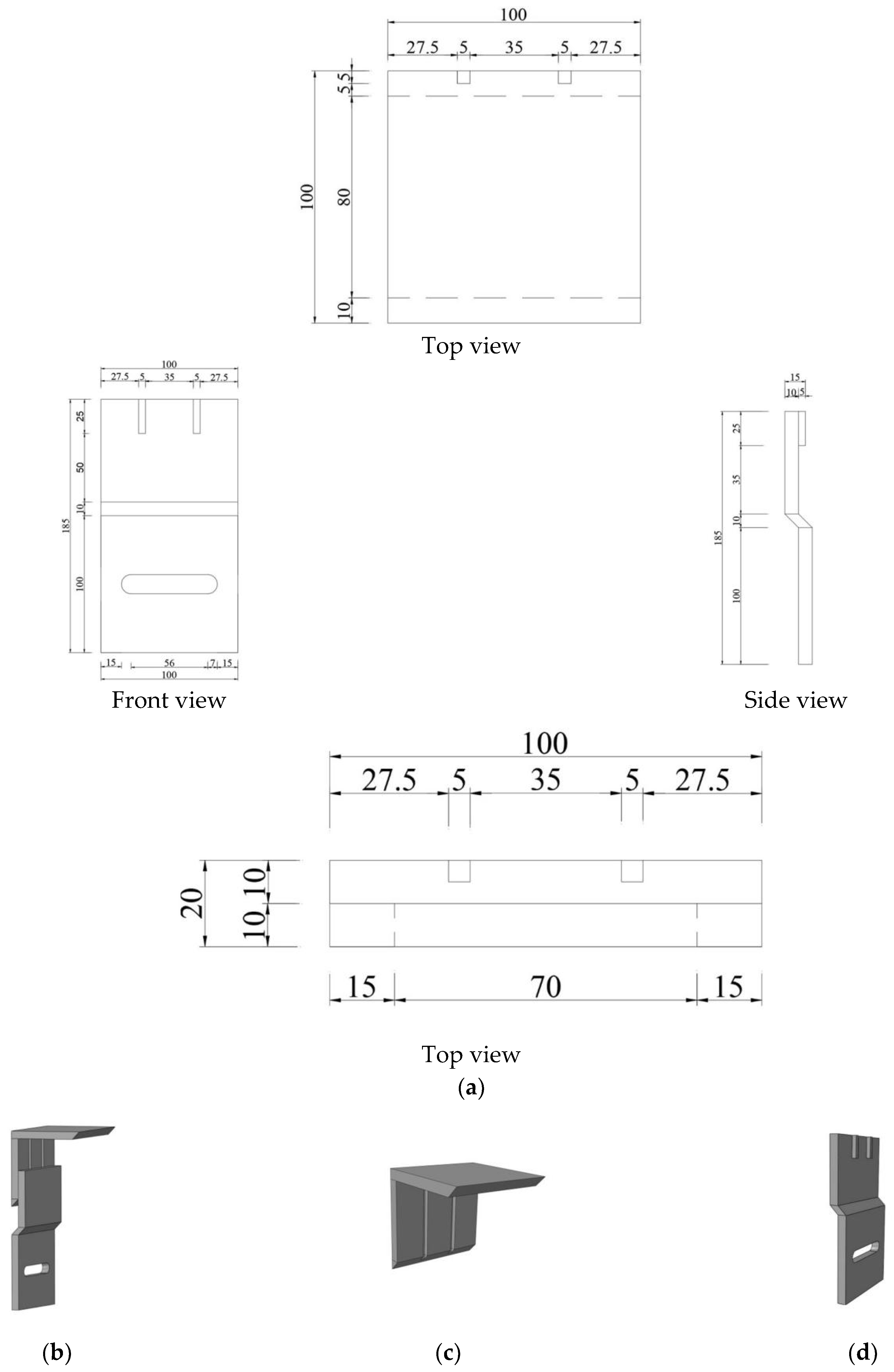
The new connector is divided into both upper and lower nodes. In which, the upper node is composed of an L-node plate and a Z-node plate, and the horizontal hole with a sliding displacement of 75 mm is designed into the lower part of the Z-node plate. The two impact dampers in the upper part of the Z-node plate provide convenience for assembling with the notch of the L-node plate. Vertical slotted holes are split in the vertical face of the lower node as the lower load-bearing node to solve the assembly error problem. The sliding mechanism transfers the load of the ALC panels to the friction force between the connector and the main structure, which effectively protects the ALC panel from serious damage. Figure 1 introduces the diagrammatic chart of the connector.
A new connector is proposed in this paper which meets the requirements of the earthquake-resistant code [23]. In a small earthquake, the ALC panel is tightly connected to the steel frames by the preload force of the bolts. The ALC panel provides lateral stiffness together with the steel frame. In a frequently occurring earthquake, the design of the connector with a long circular hole can avoid the stress concentration of the ALC panel. This design facilitates the enhancement of coordinating deformation between wall panels and the main structure. The main deterioration of the ALC panels is concentrated at the corner of the wall panels, and in the rarely occurring earthquake, because of the limited sliding displacement mechanism, this ensures that the ALC panels do not fall off.

2.2. Test Specimens

The structural systems of these two specimens are identical, but the connection type is not. DC is the classical connector of the L-hooked bolt between wall panels and main structure, and DN is a new type of connector, which is used to attach the ALC panels to the steel frame. Table 1 shows the specimen’s main connection method.
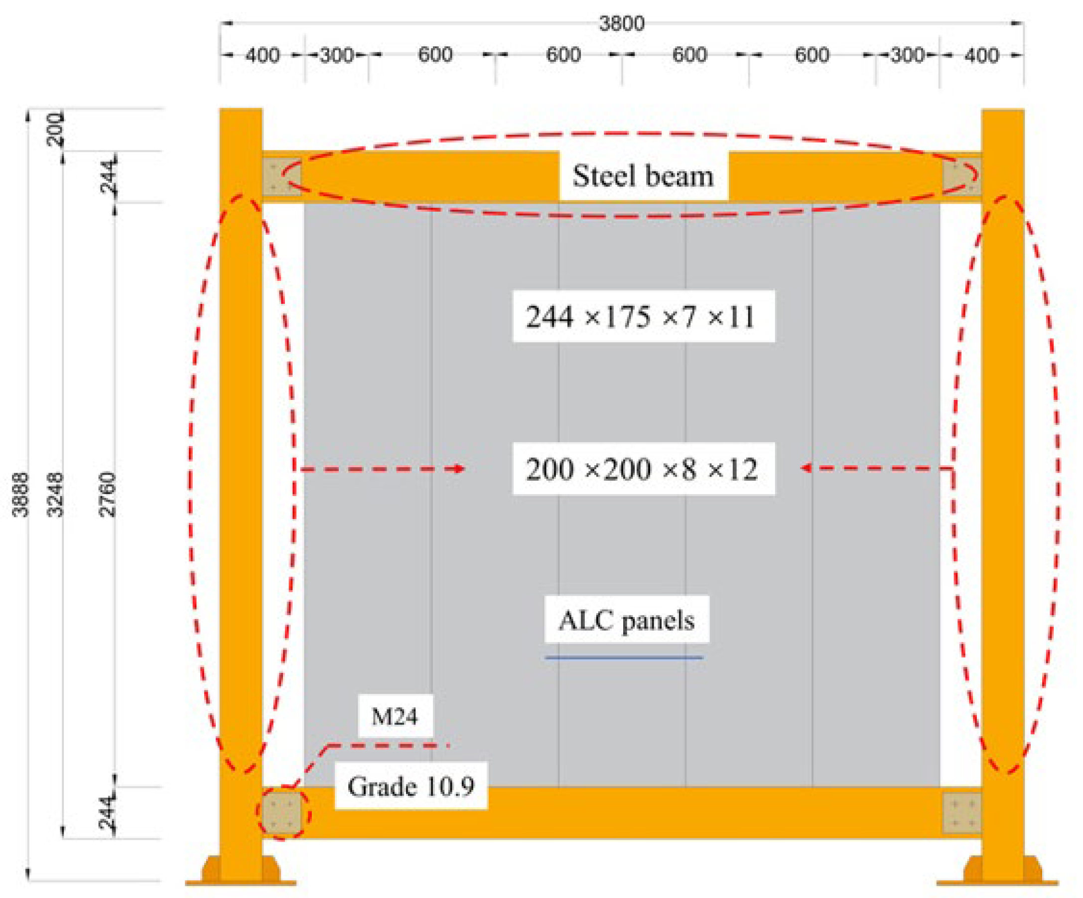
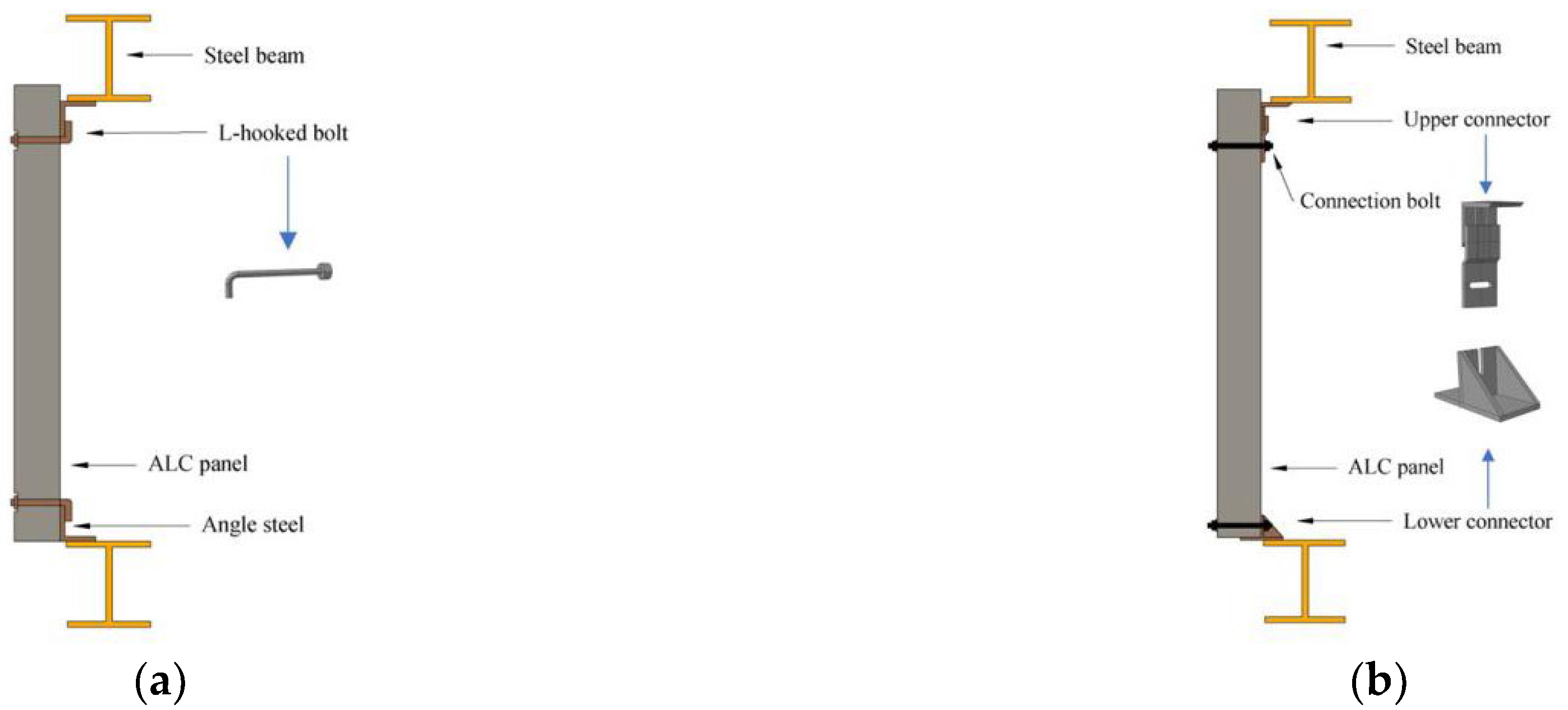
The span of the full-scale steel frame is 3800 mm and its floor height is 3000 mm, and Q235 is used for the steel beams and the steel columns. Exceptionally, the steel beam-column is assembled by the grade 10.9 of high-strength bolts and the diameter of the bolt is 24 mm. The ALC panels are designed as 200 mm × 600 mm × 3000 mm and the category of the ALC panel is A3.5 B05 standard, in which the diameter of the connecting bolt is 14 mm and the grade of the bolt is 8.8. The main parameters of the steel frame are shown in Table 2. The geometric dimension of the steel frames is shown in Figure 2. The detail of the connectors is shown in Figure 3. Connection types between the ALC panels and steel frames are shown in Figure 4. Test setups are shown in Figure 5.

2.3. Experimental Device and Loading System

2.3.1. Experimental Device

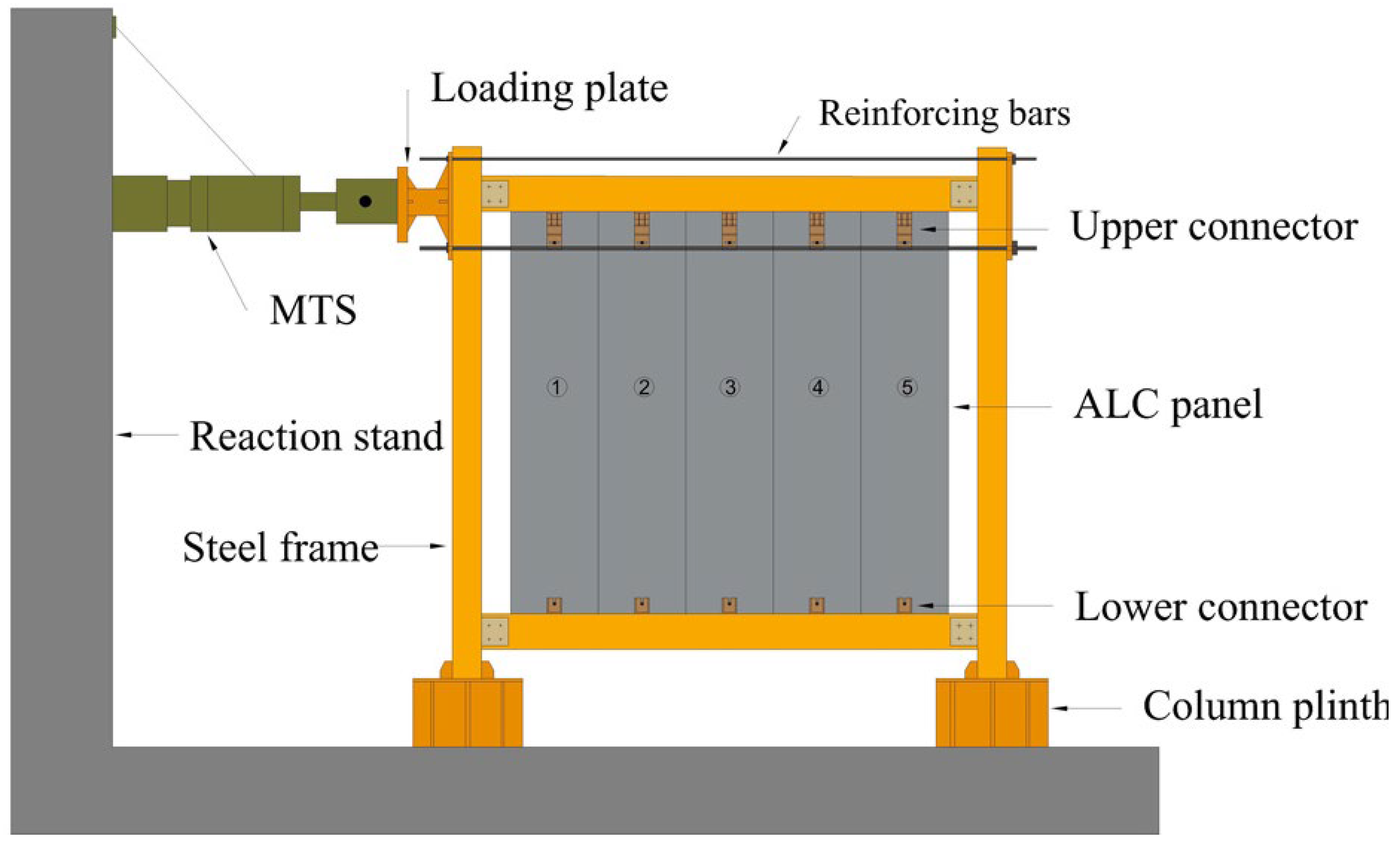
Horizontal low-cyclic loading was applied to the steel frame with the ALC panels by MTS. To reduce the influence of the steel frame’s stiffness, the frame beams and frames columns were hinged to the column plinth. Inserting four reinforcing bars which tighten bolts in the reserved holes of the top plate of the steel column could prevent the steel frames with the ALC panel from overturning during the test. Figure 6 describes the diagrammatic chart of the loading device.

2.3.2. Loading System

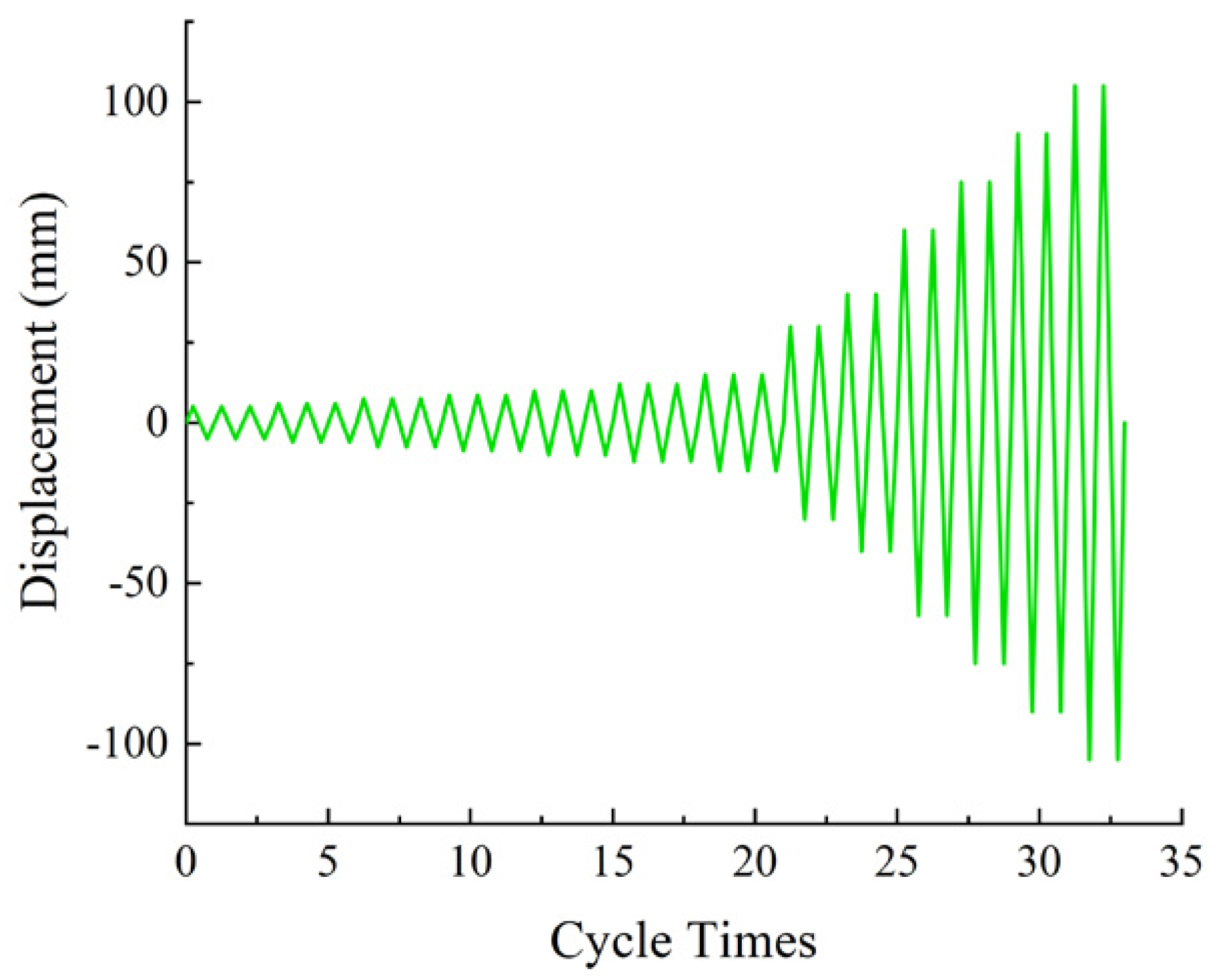
In this test, MTS was used to load horizontal low-cyclic loading for the steel frames system with the ALC panels, and the displacement-controlled loading method was used in the test. Pre-loading before the formal loading of the test was used, to check that all instruments were working properly. Then the test started the formal loading. The maximum inter-story displacement angle of frames structure requirements is referred to as the standard [23]: for light and medium earthquakes, the limit value of inter-story displacement angle is 1/250, and for rare earthquakes, the limit value is 1/50. Three turns of loading per stage until the displacement angle reaches 1/250 cycle, and two turns per stage thereafter. Figure 7 conveys a loading system.

2.4. Material Properties

The ALC cubes were poured and maintained according to the requirements of the standard of the autoclaved lightweight concrete [24]. All the specimens were constructed by ALC cubes with six sizes of 100 mm × 100 mm × 100 mm and three sizes of 100 mm × 100 mm × 300 mm. The material properties of ALC panels were determined through laboratory tests. The results reveal that the ALC panel’s average compressive strength is 3.56 MPa and the ALC panel’s average elastic modulus is 1170 GPa. Steel samples were taken from different positions of the structural model and tensile tests were carried out for steel properties [25]. The steel properties are shown in Table 3. Figure 8 illustrates the details of the material property test.

2.5. Measuring Point Arrangement

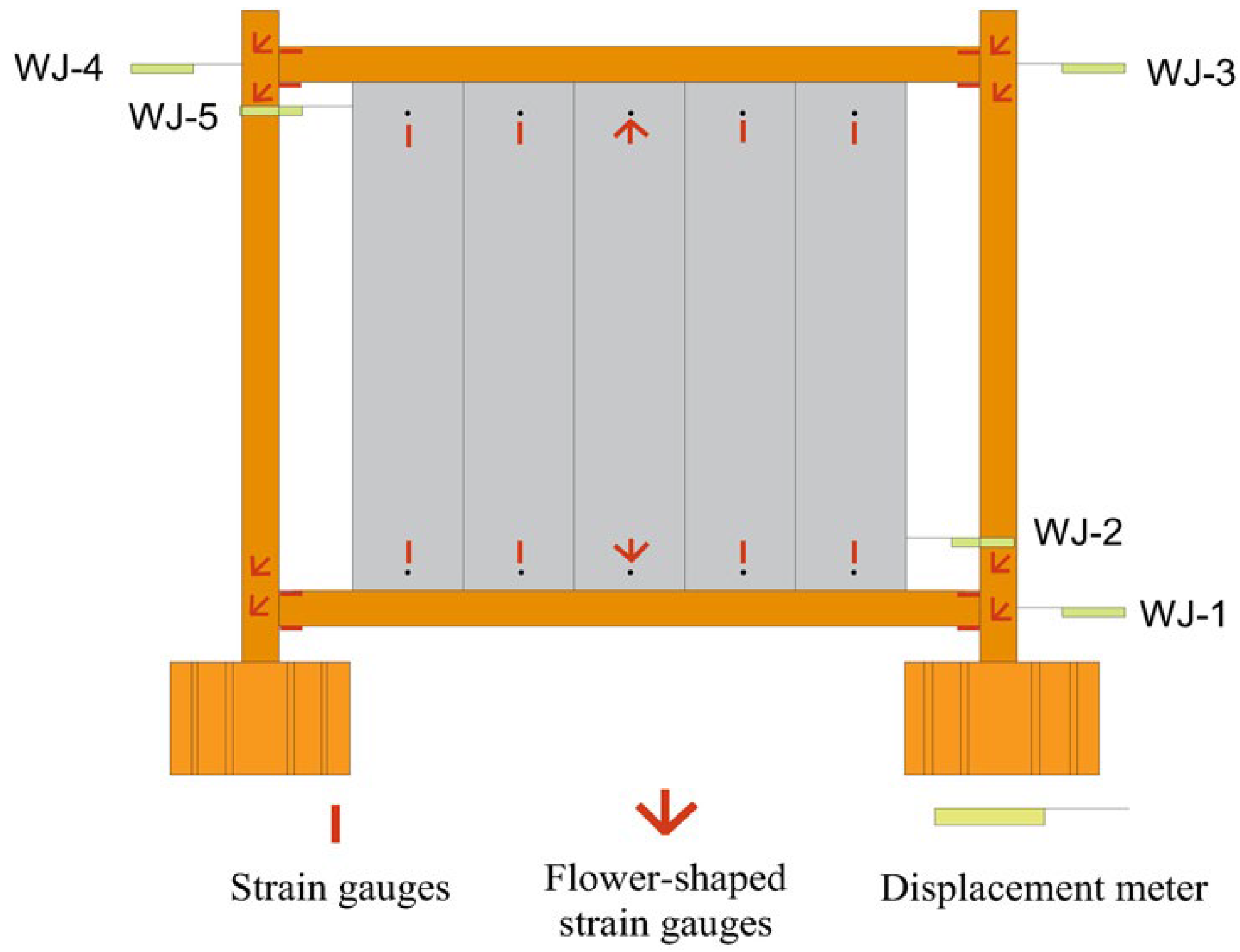
During the test, in order to determine the damage pattern of DC and DN, strain gauges were pasted at key locations such as steel frame beam-column welds, wall panels, and the connectors. It is used to observe the crack development and wall panel failure patterns and to observe the seismic behavior. Displacement meters were installed in the steel frames’ superior and inferior steel beams, which numbered WJ-1, WJ-2, WJ-3, WJ-4, and WJ-5. WJ-1 is used to monitor the slip value of the ground beam during the test and eliminates the influence of the overall slip value of the steel frames on the members in the later data analysis. WJ-2 is used to monitor the displacement at the bottom of ALC panels. WJ-3 is the displacement value of horizontal low-cyclic loading. WJ-4 is used to monitor the displacement of the upper part of the ALC panel. WJ-5 is used to monitor the displacement of the frame column during the test. Figure 9 depicts the arrangement of the measuring points.

3. Experimental Investigation

3.1. Experimental Phenomenon

3.1.1. Specimen DC

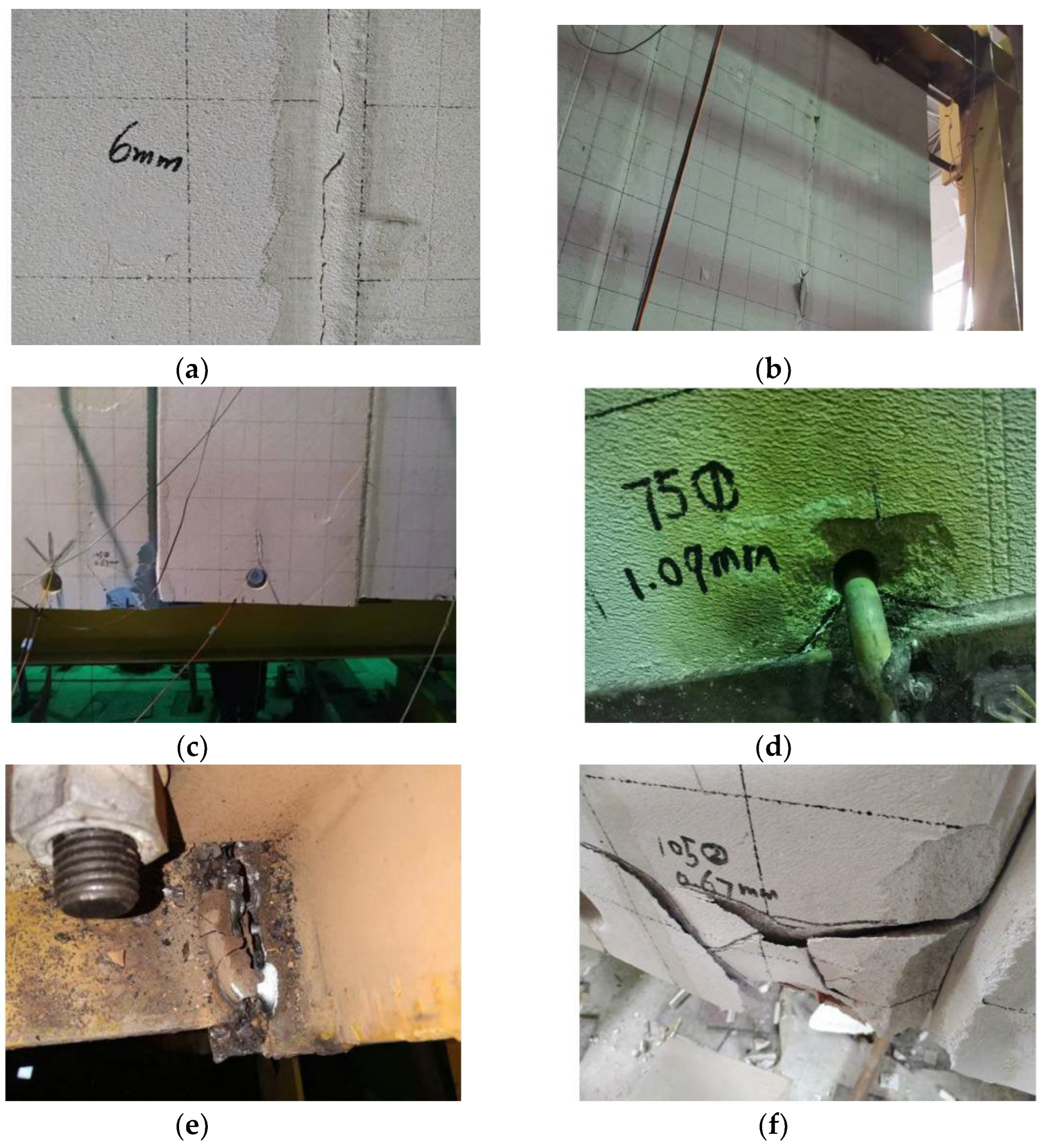
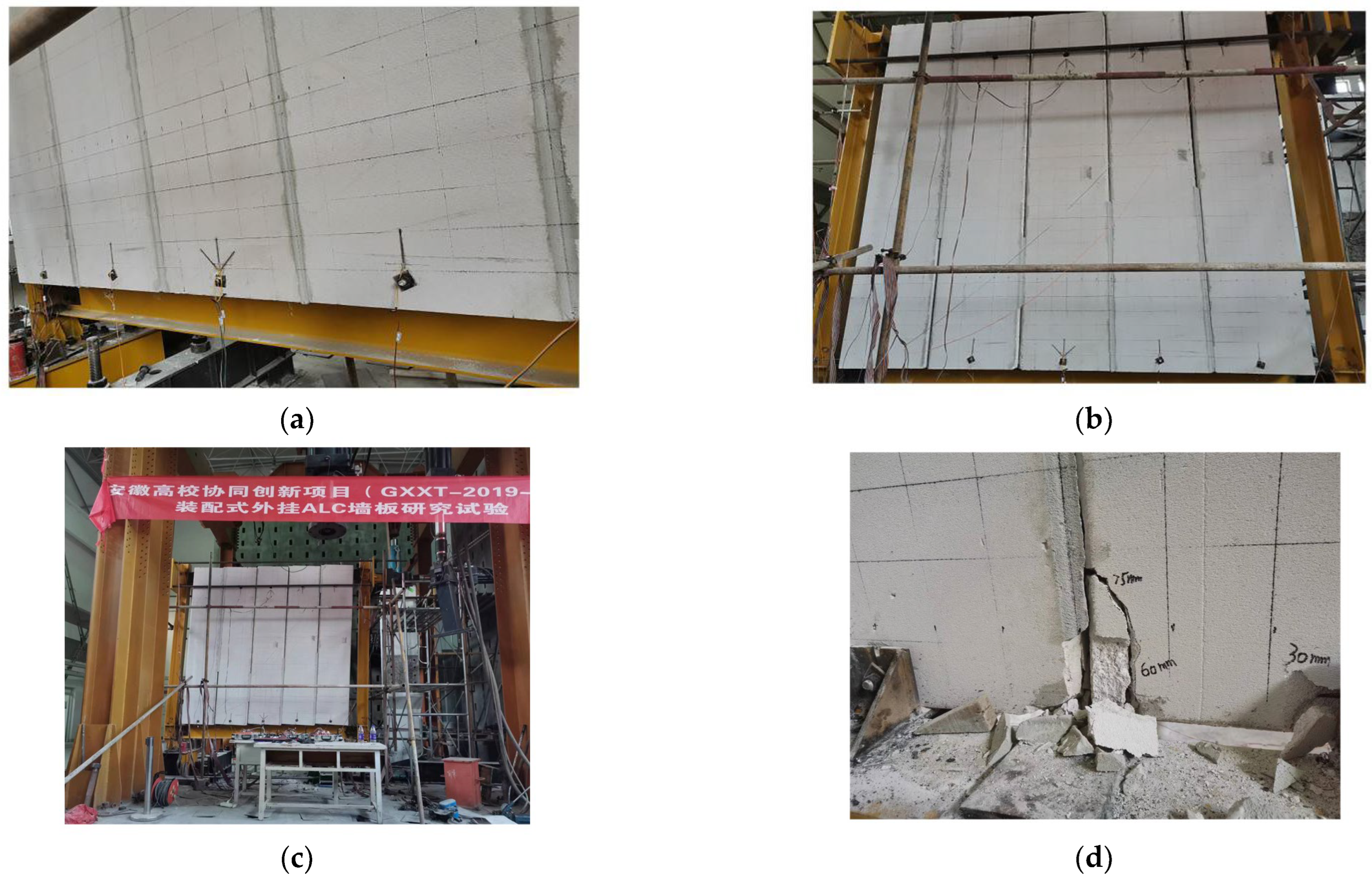
There was no obvious phenomenon at the beginning of loading. The bonding mortar between the ALC panel was not cracked. Every panel was intact and L-hooked bolts were not loose. Figure 10a showed a crack in the bonding mortar between the No. 1 and No. 2 panels during the 1/500 ( ± 6 mm) displacement angle. As the displacement angle increased, the crack expanded, and ALC panel fragments fell off, as illustrated in Figure 10b. The sound of friction between the ALC panel and the steel frame could be heard clearly during the 1/200 ( ± 15 mm) displacement angle, and obvious dislocation occurred between ALC panels where the bonding mortar was removed, as illustrated in Figure 10c. The angle steel welded to the steel beams in the upper part of the No. 2 panel fractured during the 1/75 ( ± 40 mm) displacement angle, and a splayed crack appeared around the holes of the L-hooked bolts in the lower part of the No. 3 panel, as shown in Figure 10d. Weld seams between the L-hooked bolt and angle steel on the upper part of ALC panel near the MTS mobility aid were broken during the 1/40 ( ± 75 mm) displacement angle, and there were a lot of adhesive mortars falling off. Cracks appeared in welds at the steel beam to column joints when loaded to 3/100 ( ± 90 mm), as depicted in Figure 10e. Loading the displacement angle to 7/200 ( ± 105 mm), the weld seams at the steel beam-column connection at many places of the steel frame were cracked, and the concrete at the corner of the ALC panel was crushed, as shown in Figure 10f. The test ended.

3.1.2. Specimen DN

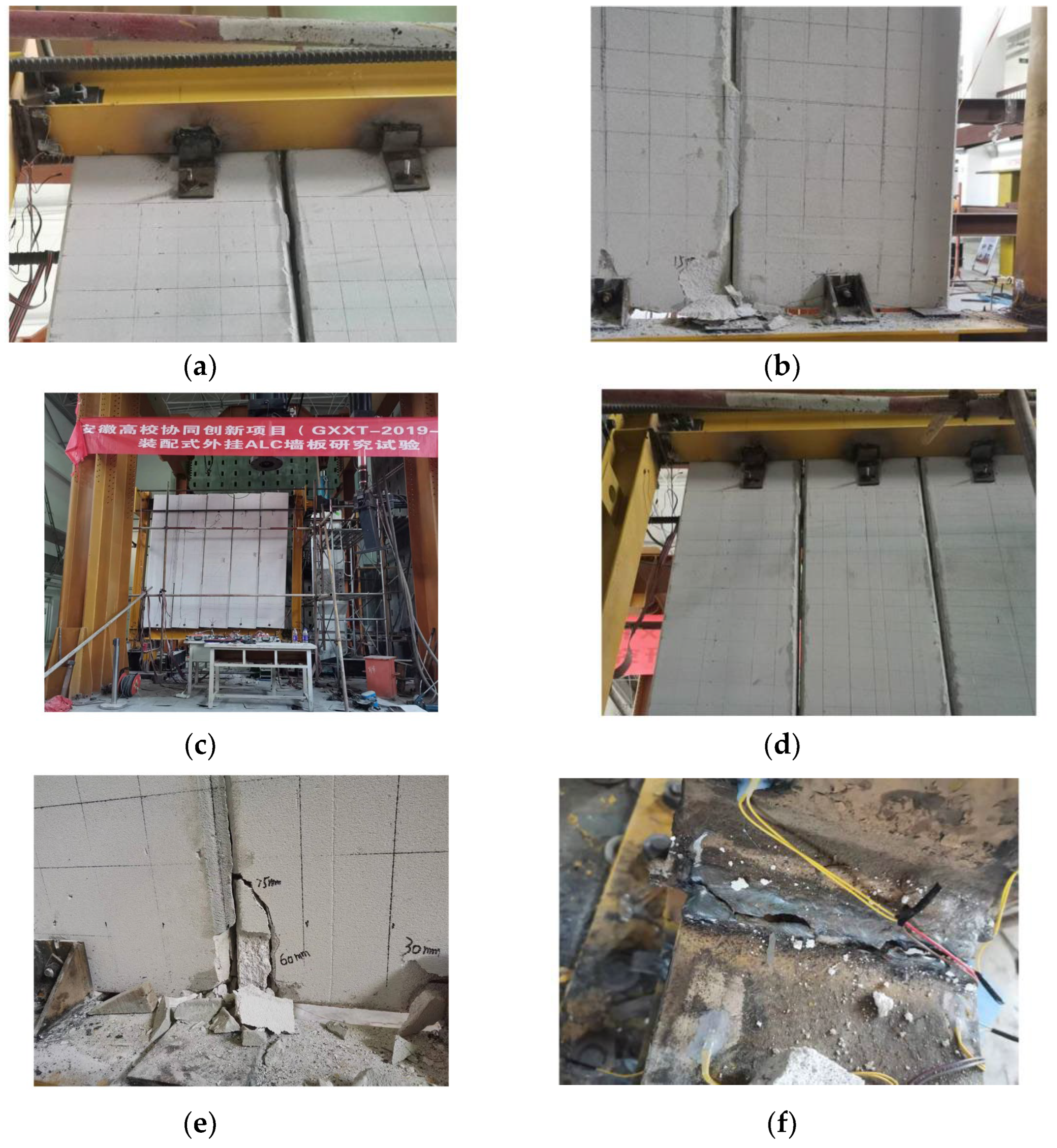
At the beginning of the loading, there were no obvious cracks occurring in the bonding mortar between the ALC panels. Moreover, the connecting bolts between the ALC panel and the new connector did not slip significantly. The loading on the ALC panel overtook the friction between the connectors and the shims when the displacement angle was loaded to 1/300 ( ± 10 mm), and the upper connecting bolts started to slightly slip in the long circular hole of the new connector. The bonding mortar between the No. 4 and No. 5 panels was dropping off, as illustrated in Figure 11a. The bolt in the connector slipped obviously during the 1/200 ( ± 15 mm) displacement angle, and there was no cracking at the connection between the ALC panels and connecting bolts. Concrete fragments were falling from the corner of the ALC panels, as shown in Figure 11b. There were no significant cracks at the connection between the ALC panel, and the connector during the displacement angle was 1/75 ( ± 40 mm). However, there was obvious dislocation in the ALC panels where the bonding mortar came off, as shown in Figure 11c. The connecting bolt moved to the boundary of the long circular hole of the pendulous Z-plate connector, as illustrated in Figure 11d. Loading the displacement angle to 1/50 ( ± 60 mm), the concrete at the corner of the ALC panels was crushed. The main damage to the ALC panel was concentrated at the corner of the ALC panel when the displacement angle was loaded to 3/100 ( ± 90 mm), as illustrated in Figure 11e. The weld seams at the steel beam-column connection at the lower left of the steel frames cracked when the displacement angle was loaded to 7/200 ( ± 105 mm), as shown in Figure 11f, and the test ended.

3.2. Experimental Results and Discussion

3.2.1. Hysteresis Curves

The hysteresis curves of the steel frames with the ALC panels under two different connection methods are compared and analyzed, as shown in Figure 12.
Similarities: (1) At the beginning of the test loading, both specimens are in the elastic stage. All parts are firmly connected, and the hysteresis curve is approximately linear. (2) With the increase of displacement, both specimens gradually enter the elastic–plastic phase from the elastic stage, and the shape of the hysteresis curve is an inverse S-shape. The envelope area of the hysteresis curve gradually becomes larger. The structure absorbs the energy by rubbing, sliding, and damaging ALC panels. (3) During the whole loading process, the hysteresis curve shows a pinned phenomenon. It indicates that the structure has slippage during loading.
Differences: (1) The hysteresis curve of DN is fuller than that of DC, which implies that specimen DN has a better energy dissipation effect than DC. (2) The two groups of tests have different pinned reasons. The main reasons for the slip deformation of DC are gaps between the bolt hole and the L-hooked bolt during the test. However, the slip deformation of DN is the design of the long circular hole. (3) The ultimate bearing capacity of DN is larger than that of DC. It indicates that the new connector has a better load-bearing capacity.

3.2.2. Coordinating Deformation Analysis

During the test for DC, the displacement of the ALC panels in and out of panels is restricted, resulting in cracks around the L-hooked bolt holes. It shows poor coordination of deformation between ALC panels and the steel frame.
DN has come up with good improvements to address this problem. The new connector combines the advantages of rigid and flexible connectors, giving full play to the lateral stiffness of the ALC panel and having good synergistic deformation between the ALC panels and the steel frame. In particular, the connection does not need to be pre-embedded and is easy to construct. For DN, in a small earthquake, the ALC panel is tightly connected to the steel frames by the preload force of the bolts. The ALC panel provides lateral stiffness together with the steel frames. In a frequently occurring earthquake, the design of the connector with a long circular hole can avoid the stress concentration of the ALC panel. This design facilitates the enhancement of coordinating deformation between wall panels and main structure, in which the main deterioration of the ALC panels is concentrated at the corner of wall panels. In the rarely occurring earthquake, because of the limited sliding displacement mechanism, it ensures that the ALC panels do not fall off. The collaboration mechanism of the wall panels and main structure is shown in Figure 13.

3.2.3. Comparison of Skeleton Curves

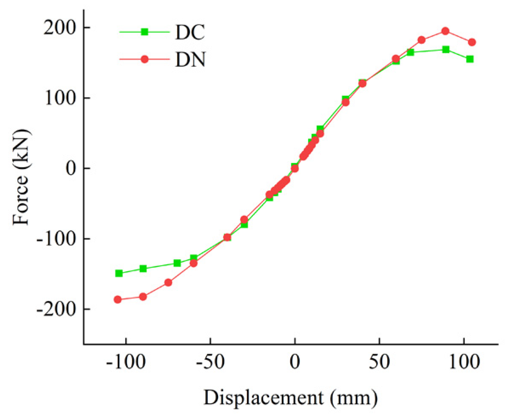
Figure 14 depicts a comparison of the two sets of skeleton curves. As can be seen from the graph:
(1)
The structure is in the elastic stage during the initial loading stage, and the ALC panels bear lateral stiffness together with the steel frame. The skeleton curve of two groups of members is nearly linear.
(2)
With the increase in displacement, the bonding mortar between ALC panels fell off and the connector slipped, indicating that ALC panels gradually withdraw from the supply of stiffness. When the structure transitions to the elastic–plastic stage, the slope of the skeleton curve gradually decreases. At this stage, the load capacity of DN is slightly lower than that of DC because of the sliding mechanism of the new connector.
(3)
When the loading displacement reached 40 mm, the connecting bolt moved to the edge of the oblong hole. The ALC panels provide lateral stiffness again with the steel frames. The skeleton curve of DN exceeds that of DC. The ultimate load of the DN appears after the connectors reach the edge of the oblong hole, indicating that the Pendulous Z-plate connector improves the bearing capacity of the structure.
(4)
Table 4 shows the characteristic value of the skeleton curve. The displacement of the yield, load yield, ultimate displacement, and ultimate load of the structure can be obtained from the table. It can be observed that the yield load of DN is 11.61% higher than the yield load of DC, and the ultimate load of DN is 14.90% higher than the ultimate load of DC.

3.2.4. Degradation of Stiffness

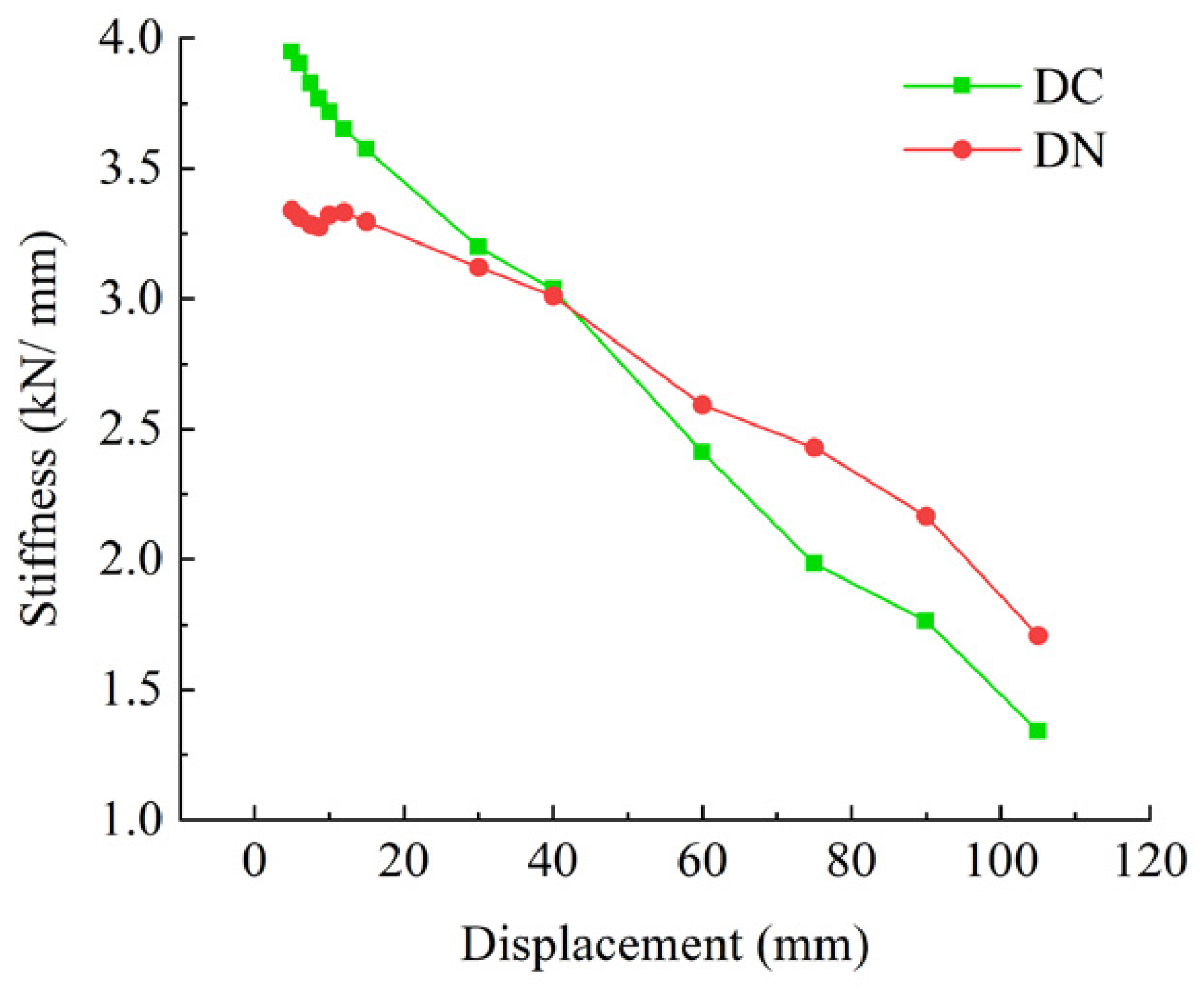
The slope K i of the line connecting each point of the skeleton curve to the origin indicates the stiffness of the specimens [26]. Figure 15 depicts how the stiffness of the two groups of the specimen degenerates over time. The initial stiffness of DC is greater than that of DN. When the loading displacement reaches 40 mm, the stiffness of DN is greater than that of DC. For DN, the main reason is that the connecting bolts slip to the boundary of the long circular hole, and the ALC panels provide lateral stiffness again with the steel frame. However, the weld in DC is cracked between the bolt with an L-hook and the angle steel, reducing stiffness. When the displacement angle is loaded to 3/100, the cracks in the steel beam-column of the weld seams appeared, and the stiffness of the two groups of the tests decreased rapidly.

3.2.5. Energy Dissipation

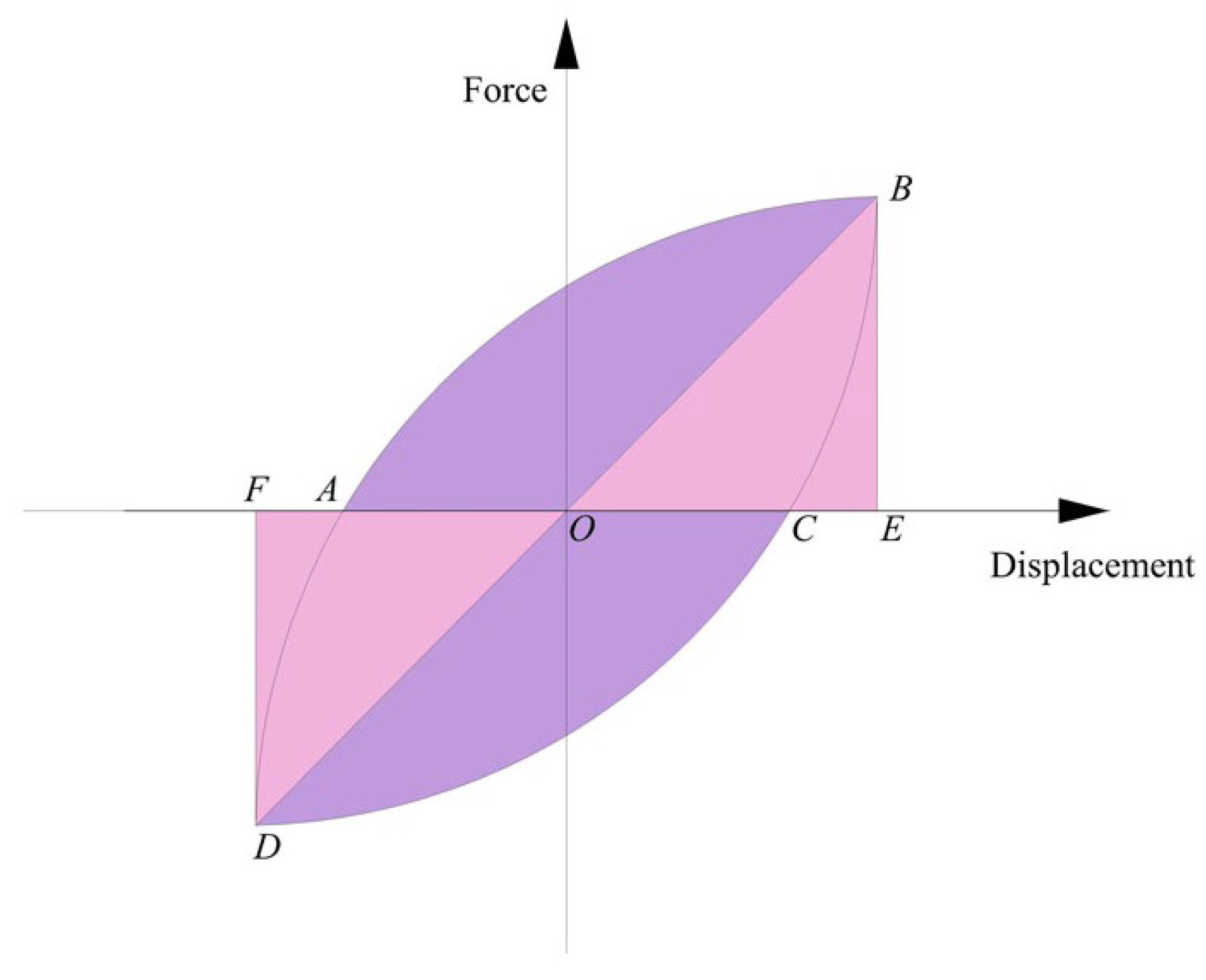
The dissipation of energy is a crucial indicator for inspecting the seismic behavior of the structure. It absorbs and transmits energy from earthquakes at the cost of plastic deformation. The better energy dissipation, the higher the structural safety and stability. The equivalent viscous damping coefficient and energy dissipation coefficient are two performance indicators of energy dissipation capacity, which are used to evaluate the energy dissipation capacity of the structure. Energy dissipation capacity indicators of the two groups of specimens are shown in Table 5. The hysteresis curve is shown in Figure 16. The equivalent viscous damping coefficient and energy dissipation coefficient are calculated by the following equation [27]:
  ξ e = 1 2 π · S A B C A + S A D C A S O B E + S O D F
E   = S A B C A + S A D C A S O B E + S O D F
where S A B C A and S A D C A is the area enclosed by ABCA and ADCA, respectively; S O B E and S O D F are the area enclosed by OBE and ODF.
As can be seen from Table 5, the total energy dissipation of DN is increased by approximately 79.95% compared to DC. The equivalent viscous damping coefficient of DN is increased by approximately 20.00% compared to DC. The energy dissipation coefficient of DN is increased by approximately 19.35% compared to DC. Overall, the steel frame structure of ALC panels connected by DN enhances energy consumption performance.

4. Finite Element Analysis

Engineers have traditionally used laboratory testing to investigate the structural performance of the steel structures subjected to earthquake loads. However, the reliance on time-consuming and costly laboratory testing has stifled progress in prefabricated structures. The use of advanced finite element tools in the building industry has improved efficient building products, and reduce the number of time-consuming and costly large-scale experiments required [28]. In this paper, finite element modeling was used to conduct an in-depth analysis of the failure mechanism and validate the results through comparison with experimental results. This paper referred to the finite element models studied by many scholars. Gad et al. [29] investigated the role of plasterboard in the lateral resistance of cold-formed steel-framed residential structures and created a finite element model. It is concluded that the presence of these boundary conditions affects the relationship between wall length and ultimate lateral load-carrying capacity of the wall system. Ding et al. [30] made the experimental tests and finite element simulations of the new connector and the traditional connector (L-hooked bolt), concluding that the analytical results of the finite element model are successfully validated against the results of the experimental tests. These works provided some useful reference for the finite element part analysis [31].

4.1. Finite Element Model

The model was created using finite element software, and the steel frame’s seismic behavior with the pendulous Z-plate connectors was investigated. To simulate the steel beams, steel columns, ALC panels, and the pendulous Z-panel connector, a hexahedral linear reduction integral solid element (C3D8R) was used. The internal reinforcement mesh of the ALC panel was simulated using the linear truss element (T3D2).
The model created by ABAQUS software was consistent with the material properties and test methods in the test. Two analysis steps were established in the model, in which the first analysis step was pre-loading and the second analysis step was controlled by the displacement loading. Furthermore, the “Tie” of the constraint condition was adopted between the steel beams and the steel columns in the model, and the “Tie” of the constraint condition was adopted between the pendulous Z-panel connector and the steel beam. In the interaction, the reinforcement mesh was embedded in the ALC panels. The coupling point XP1 was set at the loading plate at the top of the steel column. The displacement control and boundary conditions were applied at the coupling point. In particular, the steel beam-columns are connected by grade 10.9 high-strength bolts and the diameter of the bolts is 24 mm. The diameter of connecting bolt of the new connector is 14 mm, and the grade of the bolt is 8.8. Figure 17 depicts the completed model and mesh subdivision.

4.2. Comparison of Simulation and Test Results

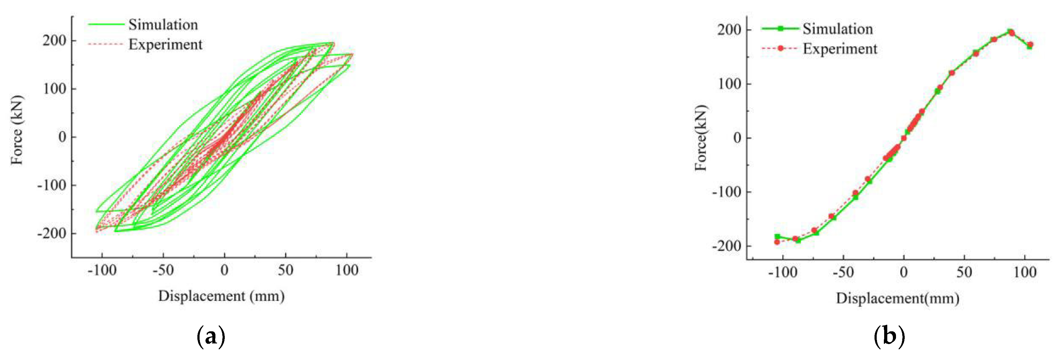
The model established by ABAQUS software is compared to the test results to ensure its accuracy. Figure 18 depicts a comparison of finite element analysis and experimental phenomena. Figure 19 depicts the comparison of simulation and experimental data results.
Figure 18 demonstrates that the ALC panel presents “saw tooth” damage in test and finite element simulations [32]. When the displacement is loaded to 40 mm, the connecting bolts move to the boundary of the new connector, which is consistent with the finite element simulation results.
Figure 19 shows that the simulated hysteresis curve is fuller than the hysteresis curve obtained from the test because the environment of finite element simulation is more ideal than the environment of the test. The trend of the two skeleton curves is similar. The pinch effect of the test is more visible than the simulation because the gaps between the specimens and the ground beam slipped during loading.
To sum up, ignoring the influence of extraneous factors, the results demonstrate that the finite element software simulation results are in agreement with the test results, and the results of the finite element simulation have a specific reference value.

4.3. Parametric Study

The connector is an essential component for ensuring a secure connection between the ALC panel and the main structure. The failure of the connector means that the panels will fall off. The connecting bolt bears the shear and tension from the ALC panel and the preload applied in the bolt, which plays a vital role in the pendulous Z-plate connector. The ordinary bolts of grade 5.6 and high-strength bolts of grade 8.8 are studied through finite element simulation to provide a reference for the depth study of the pendulous Z-plate connector in order to study the influence of bolt strength on the seismic behavior of the structure. In this article, we focus on the bolt grades M-1and M-2. The model numbers are shown in Table 6.
Two groups of finite element models with different bolt grades are established through ABAQUS software. The stress nephogram comparison of the two groups of specimens is shown in Figure 20.

4.3.1. Degradation of Stiffness

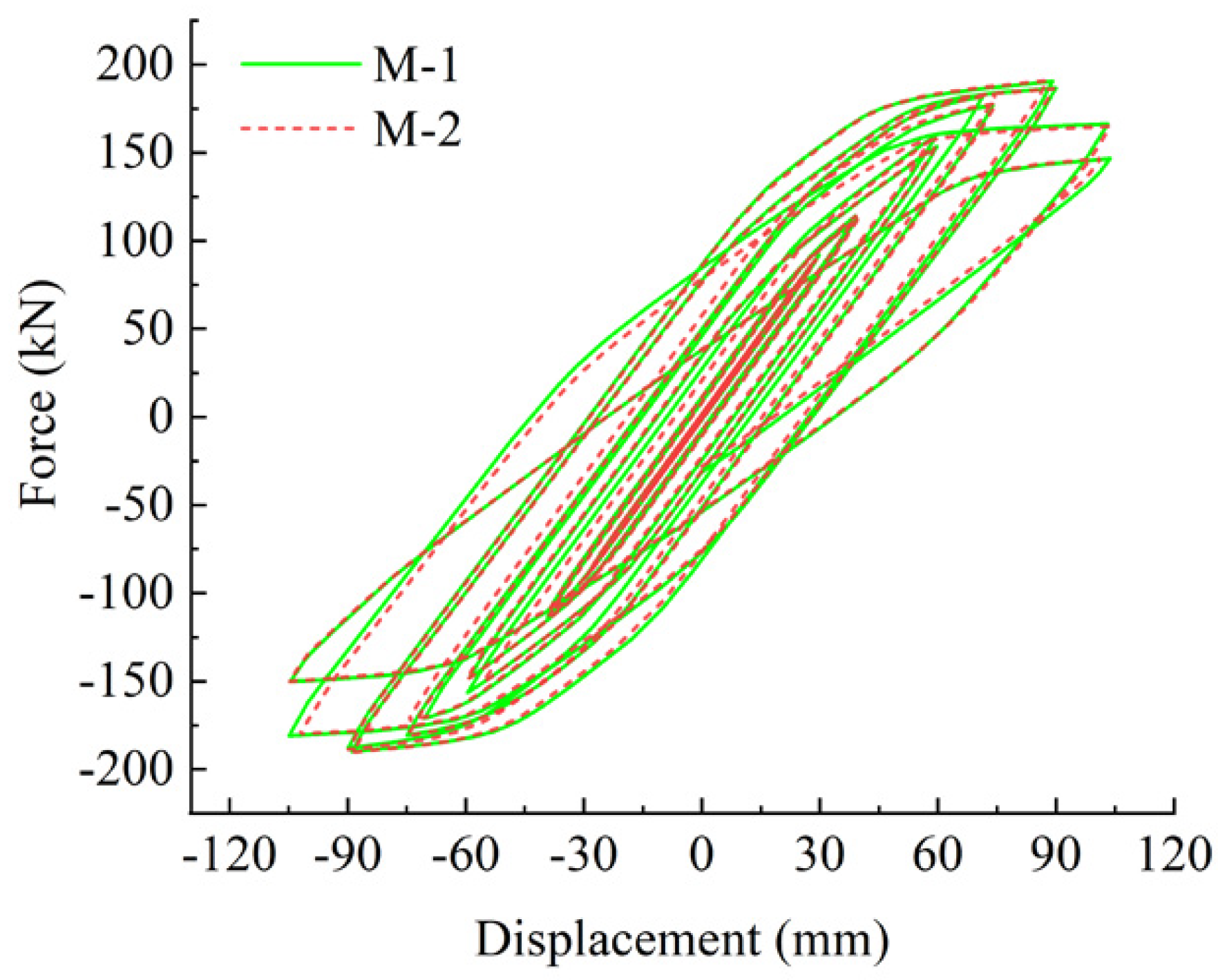
Figure 21 depicts the hysteresis curve for various bolt strengths. By comparing the two groups of hysteresis curves, the following results can be obtained:
(1)
The two groups of hysteresis curves show an inverse S-shape, and the area of the hysteresis loop increases with displacement, indicating that the two groups of specimens have good seismic behavior.
(2)
By comparing the hysteresis curves of the two groups, it is found that there is little difference between the hysteresis curves of the two groups of specimens. The hysteresis curves of M-1 are slightly fuller than those of M-2.

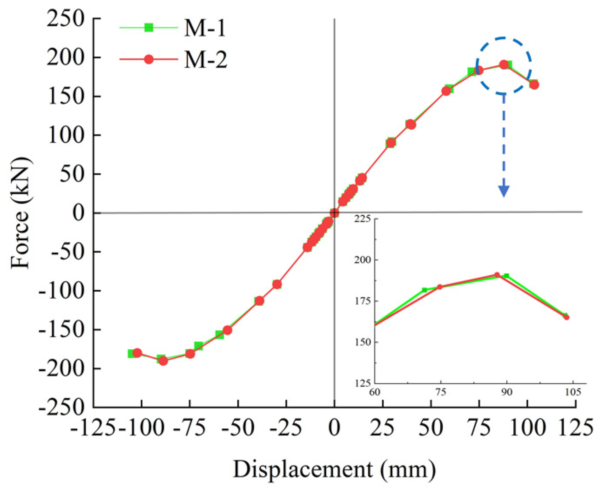
4.3.2. Skeleton Curves of Different Bolt Grades

Figure 22 depicts a comparison of skeleton curves of M-1 and M-2. Figure 22 shows that the general trend of the two groups’ skeleton curves is essentially the same, and the ultimate load capacity of M-2 is a little higher than that of M-1. It shows that M-2 has a slightly greater load bearing capacity than M-1, but the effect is not particularly obvious.

4.3.3. Energy Dissipation of Different Bolt Grades

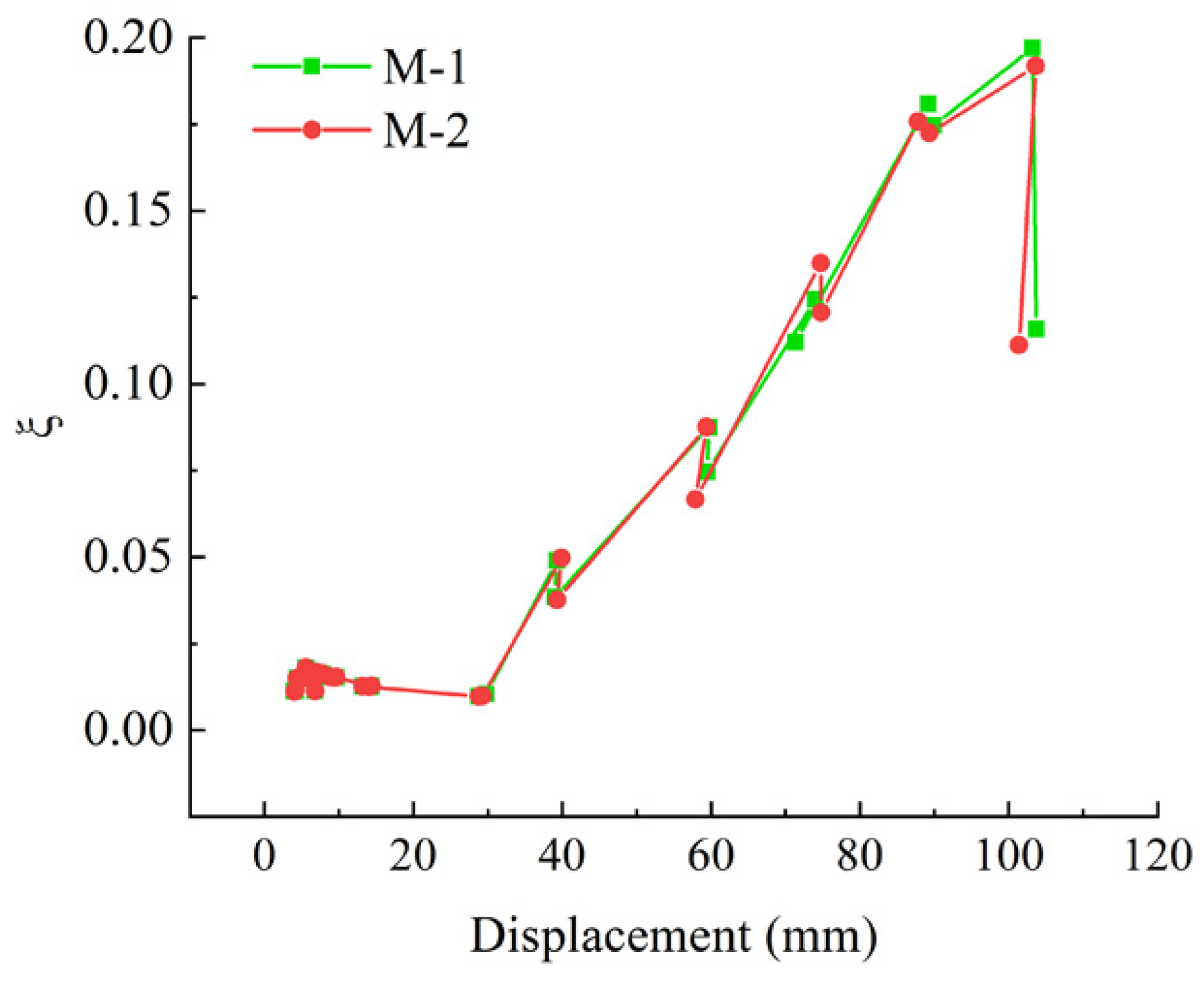
Figure 23 shows the equivalent viscous damping coefficient of M-1 and M-2. The graph clearly shows that as displacement increases, so does the equivalent viscous damping coefficient of the two groups of tests. When the displacement is loaded to 30 mm and beyond, the difference between the equivalent viscous coefficients of the two groups becomes more and more obvious. The equivalent viscous damping coefficient of M-1 and M-2 are 0.01~0.20 and 0.01~0.19, respectively. M-1 has a slightly greater energy consumption capacity than M-2, but the effect is not particularly pronounced.

5. Conclusions

This paper presents the experiments and the finite element simulations of steel frames with the classical connector and the new connector, and the seismic behavior of different bolt grades for the new connector are analyzed. The following are the significant conclusions:
(1)
The test shows that both sets of the ALC panels provide lateral stiffness together with steel frames in a small earthquake. In the frequently occurring earthquake (displacement angle of 1/250), DN provides better coordinating deformation between the ALC panel and the steel frame than that DC. In the rarely occurring earthquake (displacement angle of 1/50), the new connector keeps the ALC panel from falling off. This new connection mode conforms to the design objectives and meets the seismic minimum standards.
(2)
Based on the results of the test data analysis, it was found that the new type connector has a higher bearing capacity and energy dissipation. The hysteresis curves of specimens both gradually approached the inverse S-shape, in which DN is fuller, indicating that its energy dissipation is better. In addition, in terms of skeleton curves, the yield-bearing capacity and ultimate load-carrying capacity of DN are higher by 11.61% and 14.90%, respectively, than those of DC, and the total energy dissipation of DN is increased by approximately 79.95% compared to DC.
(3)
In the aspect of simulation, the steel frame with the ALC panel model is established based on the test. Its findings show that the simulation results agree well with the test results. This finite element model can objectively reflect the loading features of the specimens.
(4)
A parametric study was conducted using finite element software to study the influence of bolt grades on the structural performance of the new connectors. The simulation results indicate that grade 5.6 bolts are not obviously different in the structural performance than grade 8.8 bolts, in which the loading-carrying capacity of grade 8.8 bolts increases slightly, and the fullness degree of hysteresis curve does not change obviously, and the difference of the energy dissipation is not particularly pronounced compared to the grade 5.6 bolts. In consideration of the engineering costs, grade 5.6 bolts are recommended.

Author Contributions

Conceptualization, methodology, resources, supervision, writing—review and editing, K.D.; methodology, software, formal analysis software, validation, formal analysis, investigation, writing—original draft preparation, X.K.; conceptualization, investigation, S.H. and D.Z. All authors have read and agreed to the published version of the manuscript.

Funding

This research was financially supported by the University Synergy Innovation Program of Anhui Province (GXXT-2019-005).

Institutional Review Board Statement

No ethical approval was required for this study.

Data Availability Statement

The data presented in this study are available on request from the corresponding author.

Conflicts of Interest

The authors declare no conflict of interest.

References

  1. De Matteis, G.; Landolfo, R. Diaphragm action of sandwich panels in pin-jointed steel structures: A seismic study. J. Earthq. Eng. 2000, 4, 251–275. [Google Scholar] [CrossRef]
  2. Guri, M.; Brzev, S.; Lluka, D. Performance of prefabricated large panel reinforced concrete buildings in the November 2019 Albania earthquake. J. Earthq. Eng. 2021, 26, 5799–5825. [Google Scholar] [CrossRef]
  3. Cao, X.Y.; Shen, D.; Feng, D.C.; Wang, C.L.; Qu, Z.; Wu, G. Seismic retrofitting of existing frame buildings through externally attached sub-structures: State of the art review and future perspectives. J. Build. Eng. 2022, 57, 104904. [Google Scholar] [CrossRef]
  4. Arslan, M.E.; Aykanat, B.; Subaşı, S.; Maraşlı, M. Cyclic behavior of autoclaved aerated concrete block infill walls strengthened by basalt and glass fiber composites. Eng. Struct. 2021, 240, 112431. [Google Scholar] [CrossRef]
  5. Ishida, T.; Tenderan, R.; Kohtaki, K.; Kishiki, S.; Iyama, J.; Hasegawa, T.; Seike, T.; Yamada, S. Experimental study on full-scale steel moment-resisting frames with nonstructural walls subjected to multiple earthquakes. Eng. Struct. 2021, 242, 112549. [Google Scholar] [CrossRef]
  6. Wang, J.; Li, B. Cyclic testing of square CFST frames with ALC panel or block walls. J. Constr. Steel Res. 2017, 130, 264–279. [Google Scholar] [CrossRef]
  7. Ye, M.; Jiang, J.; Chen, H.M.; Zhou, H.Y.; Song, D.D. Seismic behavior of an innovative hybrid beam-column connection for precast concrete structures. Eng. Struct. 2021, 227, 111436. [Google Scholar] [CrossRef]
  8. Getz, D.R.; Memari, A.M. Static and cyclic racking performance of autoclaved aerated concrete cladding panels. J. Archit. Eng. 2006, 12, 12–23. [Google Scholar] [CrossRef]
  9. Dal Lago, B.; Biondini, F.; Toniolo, G. Experimental tests on multiple-slit devices for precast concrete panels. Eng. Struct. 2018, 167, 420–430. [Google Scholar] [CrossRef]
  10. Binici, B.; Canbay, E.; Aldemir, A.; Demirel, I.O.; Uzgan, U.; Eryurtlu, Z.; Bulbul, K.; Yakut, A. Seismic behavior and improvement of autoclaved aerated concrete infill walls. Eng. Struct. 2019, 193, 68–81. [Google Scholar] [CrossRef]
  11. Latour, M.; Rizzano, G. Seismic behavior of cross-laminated timber panel buildings equipped with traditional and innovative connectors. Arch. Civ. Mech. Eng. 2017, 17, 382–399. [Google Scholar] [CrossRef]
  12. Furtado, A.; Rodrigues, H.; Arede, A.; Varum, H. Experimental investigation on the possible effect of previous damage, workmanship and test setup on the out-of-plane behaviour of masonry infill walls. J. Earthq. Eng. 2021, 26, 5647–5678. [Google Scholar] [CrossRef]
  13. Cao, X.Y.; Xiong, C.Z.; Feng, D.C.; Wu, G. Dynamic and probabilistic seismic performance assessment of precast prestressed reinforced concrete frames incorporating slab influence through three-dimensional spatial model. Bull. Earthq. Eng. 2022, 20, 6705–6739. [Google Scholar] [CrossRef]
  14. Cao, X.Y.; Feng, D.C.; Wang, Z.; Wu, G. Parametric investigation of the assembled bolt-connected buckling-restrained brace and performance evaluation of its application into structural retrofit. J. Build. Eng. 2022, 48, 103988. [Google Scholar] [CrossRef]
  15. Dai, X.M.; Zong, L.; Ding, Y.; Li, Z.X. Experimental study on seismic behavior of a novel plug-in self-lock joint for modular steel construction. Eng. Struct. 2019, 181, 143–164. [Google Scholar] [CrossRef]
  16. Palsson, H.; Goodno, B.J.; Craig, J.I.; Will, K.M. Cladding influence on dynamics response of tall buildings. Earthq. Eng. Struct. Dyn. 1984, 12, 215–228. [Google Scholar] [CrossRef]
  17. Aref, A.J.; Jung, W.Y. Energy-dissipating polymer matrix composite-infill wall system for seismic retrofitting. J. Struct. Eng. 2003, 129, 440–448. [Google Scholar] [CrossRef]
  18. Wang, X.; Liu, X.; Ma, L.; Zhou, X. Experimental research on seismic behavior of prefabricated ALC external panels. Steel Constr. 2017, 32, 26. [Google Scholar]
  19. Wilson, J.L.; Robinson, A.J.; Balendra, T. Performance of precast concrete load-bearing panel structures in regions of low to moderate seismicity. Eng. Struct. 2008, 30, 1831–1841. [Google Scholar] [CrossRef]
  20. Okazaki, T.; Nakashima, M.; Suita, K.; Matusmiya, T. Interaction between cladding and structural frame observed in a full-scale steel building test. Earthq. Eng. Struct. Dyn. 2007, 36, 35–53. [Google Scholar] [CrossRef]
  21. Zhang, C.; Ding, K.; He, S. Seismic performance of panel connectors with steel frame based on autoclaved lightweight concrete (ALC). Buildings 2022, 12, 372. [Google Scholar] [CrossRef]
  22. Wang, B.; Wang, J.; Wan, H.; Hou, H.; Wang, J. Research on capacity and connector structure of filling wall of high-rise steel structure building under cyclic loading. Constr. Steel Struct. Prog. 2015, 17, 44–50. [Google Scholar]
  23. PRC. GB 50011-2010; Code for Seismic Design of Buildings. China Building Industry Press: Beijing, China, 2011.
  24. PRC. GB/T 11969-2020; Test Methods of Autoclaved Aerated Concrete. China Building Industry Press: Beijing, China, 2021.
  25. PRC. GB/T 228.1-2020; Metallic Materials-Tensile Testing. China Building Industry Press: Beijing, China, 2011.
  26. Ding, K.; Zhang, Y. Experimental study on seismic performance of fabricated bolted joint under low-cycle reciprocating loads. Results Eng. 2021, 9, 100208. [Google Scholar] [CrossRef]
  27. Ma, Y.; Jia, J. The influence of different parameter on the seismic behavior of SRUHSC frame. Adv. Mater. Sci. Eng. 2017, 2017, e3495150. [Google Scholar] [CrossRef] [Green Version]
  28. Mahendran, M. Applications of finite element analysis in structural engineering. In Proceedings of the International Conference on Computer Aided Engineering, Indian institute of Technology Madras, Madras, Indian, 13–15 December 2007. [Google Scholar]
  29. Gad, E.F.; Chandler, A.M.; Duffield, C.F.; Stark, G. Lateral behavior of plasterboard-clad residential steel frames. J. Struct. Eng. 1999, 125, 32–39. [Google Scholar] [CrossRef]
  30. Ding, K.; Zhang, C.; He, S.; Liu, Y. Hysteresis behavior and design of the new autoclaved lightweight concrete (ALC) external panel connector with the steel frame. Adv. Mater. Sci. Eng. 2022, 2022, e8319044. [Google Scholar] [CrossRef]
  31. Ding, K.; Ye, Y.; Ma, W. Seismic performance of precast concrete beam-column joint based on the bolt connection. Eng. Struct. 2021, 232, 111884. [Google Scholar] [CrossRef]
  32. Tian, H.; Chen, Y. Experimental research and finite element analysis on lateral shearing behavior of ALC spliced-connection wallboard. J. Build. Struct. 2009, 30, 85–91. [Google Scholar]
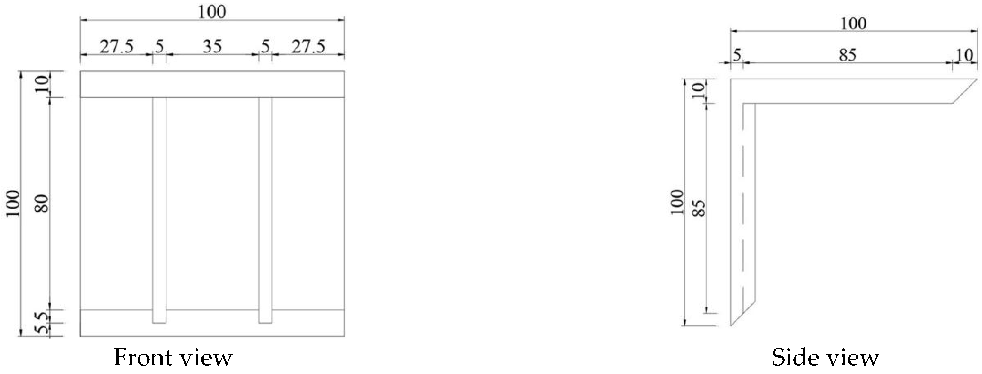
Figure 1. The diagrammatic chart of the connector. (a) Upper node, three views. (b) Upper node. (c) The L-node plate. (d) The Z-node plate. (e) Lower node, three views. (f) Front of lower node. (g) Side of lower node.
Buildings 12 02070 g001aBuildings 12 02070 g001bBuildings 12 02070 g001c
Figure 2. Dimensions of specimens (unit: mm).
Buildings 12 02070 g002
Figure 3. Detail of connectors. (a) L-hooked bolt. (b) Upper node. (c) Lower node.
Buildings 12 02070 g003
Figure 4. Connection types between ALC panel and steel beams (unit: mm). (a) The L-hooked bolt connector. (b) The pendulous Z-plate connector.
Buildings 12 02070 g004
Figure 5. Test setups. (a) Specimens of DC. (b) Specimens DN.
Buildings 12 02070 g005
Figure 6. Diagrammatic chart.
Buildings 12 02070 g006
Figure 7. Test loading scheme.
Buildings 12 02070 g007
Figure 8. Test loading scheme detailed of the material properties test. (a) The ALC cubes. (b) Steel specimens.
Buildings 12 02070 g008
Figure 9. The measuring point arrangement.
Buildings 12 02070 g009
Figure 10. Test phenomenon of DC. (a) Adhesive mortar cracking. (b) Adhesive mortar falling off. (c) Dislocation between panels. (d) A splayed crack. (e) The weld seam cracked at beam-column welding. (f) Concrete at the corner of ALC panels was crushed.
Buildings 12 02070 g010
Figure 11. Test phenomenon of DN. (a) Adhesive mortar cracking. (b) Adhesive mortar falling off. (c) Obvious dislocation between panels. (d) Connecting bolt slipped. (e) Crushed concrete at the corner of wall panels. (f) The weld seam cracked at beam-column welding.
Buildings 12 02070 g011
Figure 12. Hysteresis curves of specimens DC and DN. (a) Hysteresis curve of DC. (b) Hysteresis curve of DN.
Buildings 12 02070 g012
Figure 13. Collaborative mechanism of ALC panels and steel frame. (a) No earthquake effect. (b) Light and medium earthquakes. (c) Relative dislocation of ALC panels. (d) ALC panels cracking.
Buildings 12 02070 g013
Figure 14. Skeleton curves of specimens DC and DN.
Buildings 12 02070 g014
Figure 15. Degradation of stiffness of DC and DN.
Buildings 12 02070 g015
Figure 16. Hysteresis curve.
Buildings 12 02070 g016
Figure 17. The constructed model and mesh subdivision. (a) Finite element model. (b) Cyclic loading. (c) Boundary conditions. (d) Mesh subdivision.
Buildings 12 02070 g017
Figure 18. Comparison of results by finite element analysis and test. (a) Comparison of failure modes of ALC panels. (b) Comparison of the slipping of connecting bolts.
Buildings 12 02070 g018
Figure 19. Comparison of test and simulation data. (a) Hysteresis curves of simulation and experiment. (b) Skeleton curves of simulation and experiment.
Buildings 12 02070 g019
Figure 20. Comparison of stress nephograms of different bolt grades. (a) Stress nephogram of the grade 5.6 bolts. (b) Stress nephogram of the grade 8.8 bolts.
Buildings 12 02070 g020
Figure 21. Hysteresis curves of M-1 and M-2.
Buildings 12 02070 g021
Figure 22. Skeleton curves of M-1 and M-2.
Buildings 12 02070 g022
Figure 23. The equivalent viscous damping coefficient of M-1 and M-2.
Buildings 12 02070 g023
Table 1. Specimen’s main connection method.
SpecimenConnection Type
DCL-hooked bolt connector
DNThe pendulous Z-plate connector
Table 2. The steel frame’s main dimensions.
SpecimensCross-Sectional Specifications
Frame columnHW 200 mm × 200 mm × 8 mm × 12 mm
Frame beamHM 244 mm × 175 mm × 7 mm × 11 mm
Table 3. Material properties index of steel.
SpecimensThickness (mm)Yield Stress (N/mm2)Ultimate Stress (N/mm2)Elongation Stress
Steel beam web7275.3411.322.3%
Steel column web8278.2409.820.8%
Steel beam flange11263.4401.625.2%
Steel column flange12289.5435.524.7%
The new connector10376.6510.119.6%
Table 4. Characteristic value of skeleton curves.
Loading MethodYield Displacement (mm)Yield Loading (kN)Ultimate Displacement (mm)Ultimate Loading (kN)
DC50.05137.2968.58168.70
DN58.82153.2388.35193.83
Table 5. Parameters of energy dissipation.
SpecimenLoading Displacement (mm)Total Energy Dissipation (kN·mm)The Equivalent Viscous Damping CoefficientEnergy Dissipation Coefficient
DC1059633.250.100.62
DN10517,335.470.120.74
Table 6. Finite element model.
Model NumberBolt Diameter (mm)Bolt Grade
M-1145.6
M-2148.8
Publisher’s Note: MDPI stays neutral with regard to jurisdictional claims in published maps and institutional affiliations.