Article

Architectural Formation of Growable Light Steel Structure and Its 3D Visualisation Design and Construction Method

1
Department of Civil Engineering, School of Architectural Engineering, Jinling Institute of Technology, 99 Hongjing Avenue, Jiangning District, Nanjing 211169, China
2
Department of Civil and Environmental Engineering, College of Design and Engineering, National University of Singapore, 21 Lower Kent Ridge Road, Singapore 119077, Singapore
3
Department of Civil Engineering and Environmental Management, School of Computing, Engineering and Built Environment, Glasgow Caledonian University, Glasgow G4 0BA, UK
4
Department of Architectural Science and Technology, School of Architecture, Southeast University, Si-Pai-Lou 2#, Nanjing 210096, China
*
Authors to whom correspondence should be addressed.
Buildings 2022, 12(11), 2041; https://doi.org/10.3390/buildings12112041
Submission received: 15 September 2022 / Revised: 1 November 2022 / Accepted: 18 November 2022 / Published: 21 November 2022

Abstract

:
With the applications of new construction technologies and design ideas, innovative construction methods and architectural designs promote overall productivity and enrich architectural impressions. However, faced with the contradictions between construction efficiency, project benefits, and sustainability, together with the dynamically variable social demands and monotonous design of current temporary light steel structures, a new type of growable light steel structure with parameterisable and assembled architectural units is proposed. Besides, a fast-assembled track foundation that can be detachable and recycled is adopted. Both can promote the growth of light steel units. To be specific, its architectural spaces can be extended and contracted, and the structural form and service space can be adjusted by the reorganisation and optimisation of unit arrangements. Meanwhile, due to the advantages of information integrations and 3D visualisations of BIM technology, a BIM-based design and construction method of growable light steel structures is studied. Based on the arrangements of track and parametrically transformed light steel units, this study expands the architectural forms of light steel structures. It explores their respective applications in practical architectural design to solve current shortages of land resources, properly respond to variable building environments, simultaneously enrich the design schemes of current light steel structures, improve the utilisation rate of structural spaces, and enhance the aesthetic sensations of buildings.

Graphical Abstract

1. Introduction

Temporary buildings are generally defined as buildings or structures that are constructed for temporary use, e.g., post-disaster shelters, temporary exhibitions, or public activities, which will be demolished within a specified period of time [1]. During the global COVID-19 pandemic period, a mobile cabin hospital, known as Fangcang Hospital in Wuhan, China, a typical type of temporary building, was rapidly built to accommodate and treat infected patients, eventually helping prevent the continuous spread and outbreak of the viruses [2]. As a good example of temporary buildings, this temporary hospital presented large advantages of rapid construction, high flexibility, and sustainability by adopting light steel materials, modular construction methods, and BIM-aided technologies. However, in the past, due to the short life cycle and poor awareness of sustainability and environmental protection, many non-recyclable economic materials, such as concrete, were used for construction [3] to reduce the costs, which makes this type of rigid structure less adaptable and variable for dynamically changing environments or recycling applications and finally leads to a waste of materials after demolitions [4].
In recent years, more and more research has focused on how to improve the sustainability [5] and human comfort of temporary buildings while maintaining the rapid construction characteristics at the same time by applying new materials [6,7] or proposing new design schemes. Grosso and Thiebat [8] proposed a life-cycle environmental assessment method based on the embedded energy calculations of respective components related to foundations, structures, and envelopes of buildings made of different construction materials. Through a case study, considerations of energy efficiency and environmental impacts proved to be necessary, especially during the early design phase of a project. Yun et al. from Yonsei University in Korea [6] came out with a practical solution to adopt phase change materials (PCMs) to help stabilise and control room temperatures in temporary hospitals (Figure 1) in case excessive temperature differences would cause more dissolved viruses in the humid air and increase the infection risks, verifying this solution based on box experiments. This idea was also proposed and discussed by other researchers [9,10,11] through numerical simulations. Zhu et al. [9] noticed that applying single-orientation PCMs with reasonable thicknesses could obviously improve indoor thermal comforts, and optimised multi-orientation PCMs could ensure a comfortable indoor temperature under extreme closed conditions without any mechanical cooling systems in temporary lightweight buildings. Regarding novel design ideas, Köhler believed that the traditional holistic, top-down completion thought could be replaced by a discrete design [12], i.e., the design of discrete components or functional units. Based on this idea, Chen et al. [3] gained their inspiration from traditional Chinese mortise and tenon structures, made use of a self-developed program based on the Rhino platform, designed a novel aluminium SUP structural system (Figure 2), and initially verified its structural stability through experiments.
Similarly, as for public buildings, energy efficiency has been a critical topic explored by many researchers and architects. Some studies concluded from case studies [13] that under the COVID-19 restrictions and easing policies, the energy consumption of some public buildings, especially museums, libraries, and school buildings, would present apparent drops compared to the pre-pandemic situations due to the changed lifestyle and use frequency. However, after more measures were released in many countries, rapid recoveries can be seen for service industries and social activities. As hosting facilities, these public buildings have to re-accommodate the increasing number of visitors and spend extra expenditure on indoor ventilation and hygiene maintenance, which means that more energy would be consumed and more necessities are considered. He and Zhang [14] established a bi-objective optimisation model to minimise the energy consumption and investment costs of a university office building in Qingdao, China, by considering its architectural and social environments. Similarly, Guo et al. [15] from Tianjin University, China, proposed and verified a three-level comprehensive evaluation model based on the analytical hierarchy process (AHP) and the fuzzy mathematics theory by outputting a unified score from several performance indicators, which could help and establish improvement measures in a specific way. Wang [13] also noticed the energy consumption issue but paid more attention to the assessments and evaluations of indoor environment quality and operation performance before and after the COVID pandemic. Through the comprehensive analysis of two engineering cases in Dalian, China, it was found that adopting energy-saving air conditioning systems and other equipment would enhance economic efficiency. Meanwhile, various evaluation indicators, such as PM2.5 and CO2 concentration, sunshine duration, and humidity, have been significantly improved. However, social benefits are insufficient due to unreasonable space design and utilisation.
With the era of Industry 4.0 coming, more innovative technologies and ideas are put into practice within the architectural engineering domain. Modular construction systems (MCSs), normally defined as the manufacture of components and pre-assembly of elements or modules in the factory before final installation into the planned location, have been researched and adopted in several countries, e.g., China, Malaysia, and Singapore [16,17,18]. Li and Deng [1] from Southeast University in China adopted an idea from the container buildings and honeycomb structures and designed a new lightweight reconfigurable structure system. Through the numerical simulations and field experiments, the structural stability, comfort degree, and operating energy consumption were assessed and proved to meet the demands of people of different ages and even different social strata. Prefabricated Prefinished Volumetric Construction (PPVC) is a specific term in Singapore to describe a construction method. Hence, free-standing volumetric modules completed with finishes for walls, floors, and ceilings, see Figure 3, are constructed and assembled or manufactured and assembled [18]. Through considerate designs and abundant engineering practices, PPVC has been proven to greatly improve productivity by up to 40%, reduce the input of on-site manpower and help create better construction environments and quality controls.
Connection is the key part of the structural design of modular steel buildings. It must meet the requirements of multi-modular rapid connection formation, high strength, reasonable erection, reliable force transmission, etc. Lyu et al. [19,20] conducted comprehensive research on a full-scale corner-supported modular building assembled with splice connections (Figure 4) and the basic bending behaviors of these splice connections (Figure 5). Zhai et al. [21] conducted full-scale experiments on the connections under monotonic and cyclic loadings, and the failure modes and static and hysteretic performances of the connections were manifested.
In addition to modular constructions, growable architecture and movable structure are two new concepts proposed by some architects in order to create more possible architectural formations, and present more aesthetic appearances and changeable structural spaces in response to currently diverse and uncertain project demands, especially in this post-pandemic period. Zhou [22] proposed a growable and changeable school building in 2010, a basic double-frame structure growing in a plane extension mode, and initially discussed its growth possibility, applicability in variable ground levels and prospects for sustainable development. Recently, a design team from Institute for Advanced Architecture of Catalonia (IAAC) in Spain [23] expressed their ideas, which are originated from cell growth, and took advantage of Grasshopper and the Anemone plug-in, based on iterative algorithmic strategies, starting from elementary spatial building blocks and finally forming a coherent architectural system.
As to the structural space modifications, Angeletou [24], a project designer from Austria, came out with a public movable structure system (PMSS) to realise space customisation by the users. In Figure 6, it is clear to see a basic structural unit and the rail on the ground. By properly sliding the units and connecting them using reliable mechanical bolts, a specific structural space would be created for holding public activities. It could be set together and placed on one side to release the free public space again.
Thus, with the increasing diversity and uncertainty of urban construction demands, the contradictions between the construction cycle, service life, and function of buildings have been increasingly prominent [25]. Temporary buildings are usually adopted as a practical solution to this issue. Light steel temporary buildings with short construction periods, economy, mobility, and sustainability have been favoured by many architects and engineers. At the same time, China is encouraging building informatisation, green architecture, and construction industrialisation, and advocating applying cutting-edge technologies to practical projects.
For example, BIM technology is applied in the planning and design of prefabricated steel structure engineering, component prefabrication, on-site construction, etc. It plays a vital role in productivity improvement and sustainable development of the building industry. However, as the general structural form of temporary buildings in China [26], light steel structure is relatively simple and traditional, i.e., lacking innovation and transformation, leading to monotonous designs and similar architectural performances. Therefore, based on the reviewed design ideas and current research status, this study would propose a new growable and movable structural system to cater to demands of sustainability, rapid construction, modifiable structural spaces oriented by users’ needs, and building functions, combined with the advantages of highly integrated information management platforms to finally realise a rewarding circle of multiple architectures, environments, and social benefits.

2. Characteristics of the Proposed Novel Type of Growable Light Steel Structure

This study puts forward a new growable light steel structure by learning lessons from the biological process of cell division growth, which adapts cross-shaped equilateral steel angles with a column foot panel as the basic unit. The layout of structural units is carried out in conjunction with the track foundation, and the overall architectural space is completed through its horizontal and vertical developments, i.e., the initial growth of structural units. When the building function and external environment change, the overall structure can still rely on the movement of units and the transformation of the foundation track to realise the extension and contraction of the space, adjusting the structural form and utilisation space [27], i.e., the second growth of the building space, reorganisation, and optimisation.

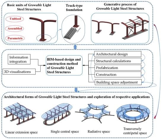
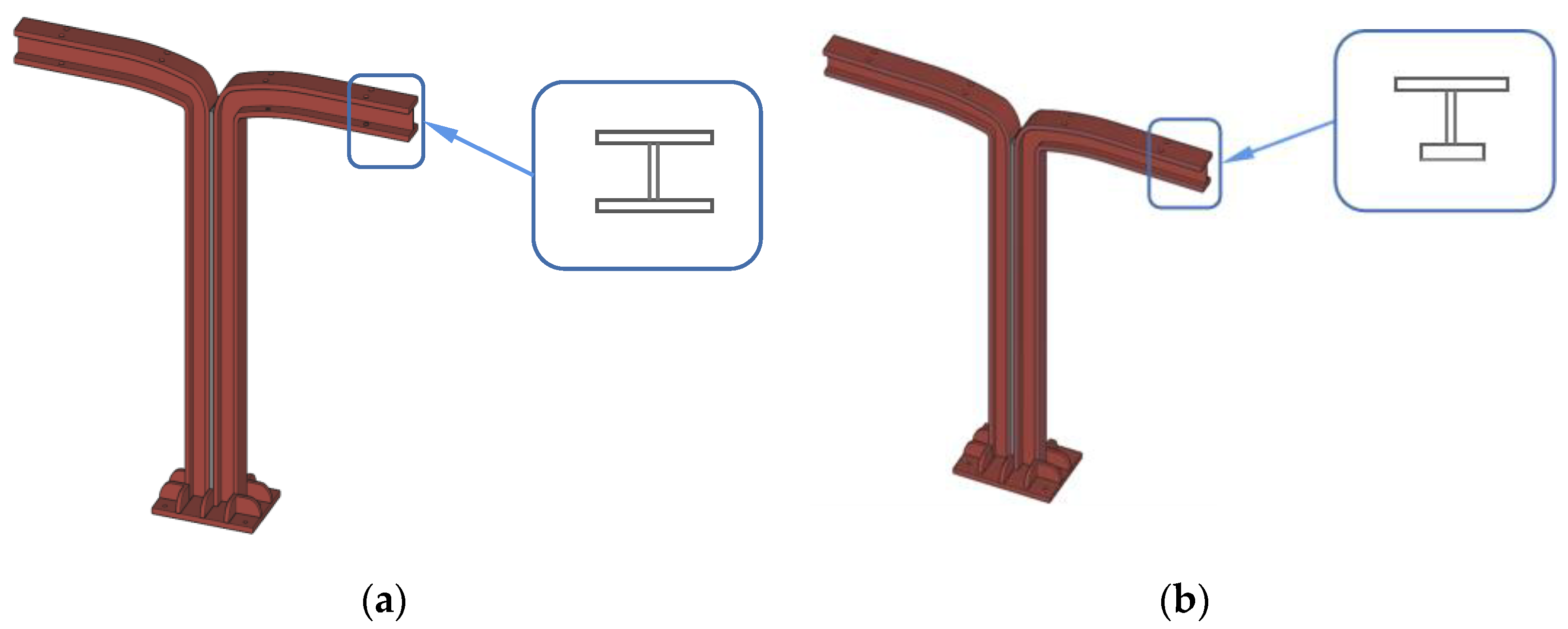
2.1. Proposed Basic Units of Growable Light Steel Structures

Considering the disadvantages of the existing light steel structures with monotonous forms and lack of innovations, combined with three factors, i.e., environment, structural space demand, and function, a basic unit for new growable light steel structures, as shown in Figure 7, is proposed, including overhanging steel cantilever, column body, and column base.
The dimensions of the basic units can be selected during the design process according to the building requirements. The height of the basic unit, as shown in Figure 7, is 4.5 m, and the span of the cantilever is 3 m. In Figure 7, the column section is a cross-shaped section composed of 4 steel angles and the filled plates, and a single angle steel is an equilateral steel angle of 180 mm × 18 mm. Meanwhile, the beam is a T-shaped section composed of two equilateral steel angles. Therefore, the height of the beam is 180 mm. The finite element analysis was used to analyse the mechanical properties of the structure, and the von Mises stress and deformation contours of the unit model were obtained (Figure 8). Due to the dynamically variable social demands, growable light steel structures are proposed as temporary light steel structures, which have low requirements on the load-bearing capacity. During the finite element analysis, vertical loads are applied onto the structure, which is considered the combination of the permanent load (including the dead loads of structural and non-structural members applied on the structure) and the variable load (including live roof load, snow load, and ash load). It is clear that the basic unit is the cantilever component with a simple structure, reasonable stress, and a clear force transmission path. The cantilever transfers the vertical loads to the base through the steel column.
To expand the application range of growable light steel structures, various sections could meet more architectural requirements. Two new forms of sections, as shown in Figure 9, are proposed for designers to choose from. In future study, the cross-section form of the basic unit in Figure 9 will be taken as the research object.

2.2. Characteristics of Basic Units of Growable Light Steel Structure

The basic unit of a light steel structure contains three characteristics [28], i.e., unitised, assembled, and parametric [27], where unitised implies the foundation, assembled the process, and parametric the method. All the above concepts are unified in the construction of the growth-type building.
(1) Unitised: The basic unit is the fundamental of growable light steel structures. By reasonable assembly and connection of structural units, the final building formation can be determined. At the same time, it is also the basis of the structural, spatial reorganisation, and optimisation of the growable light steel structure to realise growth in multiple directions.
(2) Assembled: The basic unit and the spatial structure formed by this kind of growable light steel structure belong to the prefabricated steel structure. The components and the connectors between the units are almost standard. They can help promote prefabrication in the factory, simplify the construction technique, reduce the construction process, save labour input, and improve construction efficiency.
(3) Parametric: To further improve the space utilisation rate, further develop the architectural function, and at the same time express the aesthetic feelings of space based on the form and size of the standard units, the height and span of the unit are parameterised to meet different building functions and modeling requirements. According to the parametric variations in the height and span, the basic unit can be divided into three categories, i.e., different spans of the same height, different heights of the same span, and different heights and spans, as shown in Figure 10. Based on specific terrain conditions and site planning, parameterised units can be properly adopted in the design process of structural layout and architectural shape formation for the changeable construction areas and the upper space, combined with reasonable building interior functional partitions to further expand the service functions. In addition, the building façades can also reflect scattered and undulating heights and express aesthetic feelings about the space.

3. Architectural Formation of Growable Light Steel Structures

By making use of the proposed light steel units, tie bar system, and track-type foundation, the main structure skeleton could be formed. Combined with external walls, roof panels, and other envelopes, the final building entity can be built. The number and spacing of a single frame and the number of basic units contained in the whole structure are not limited and are designed to realise the free growth of the building space horizontally and vertically according to practical engineering needs.

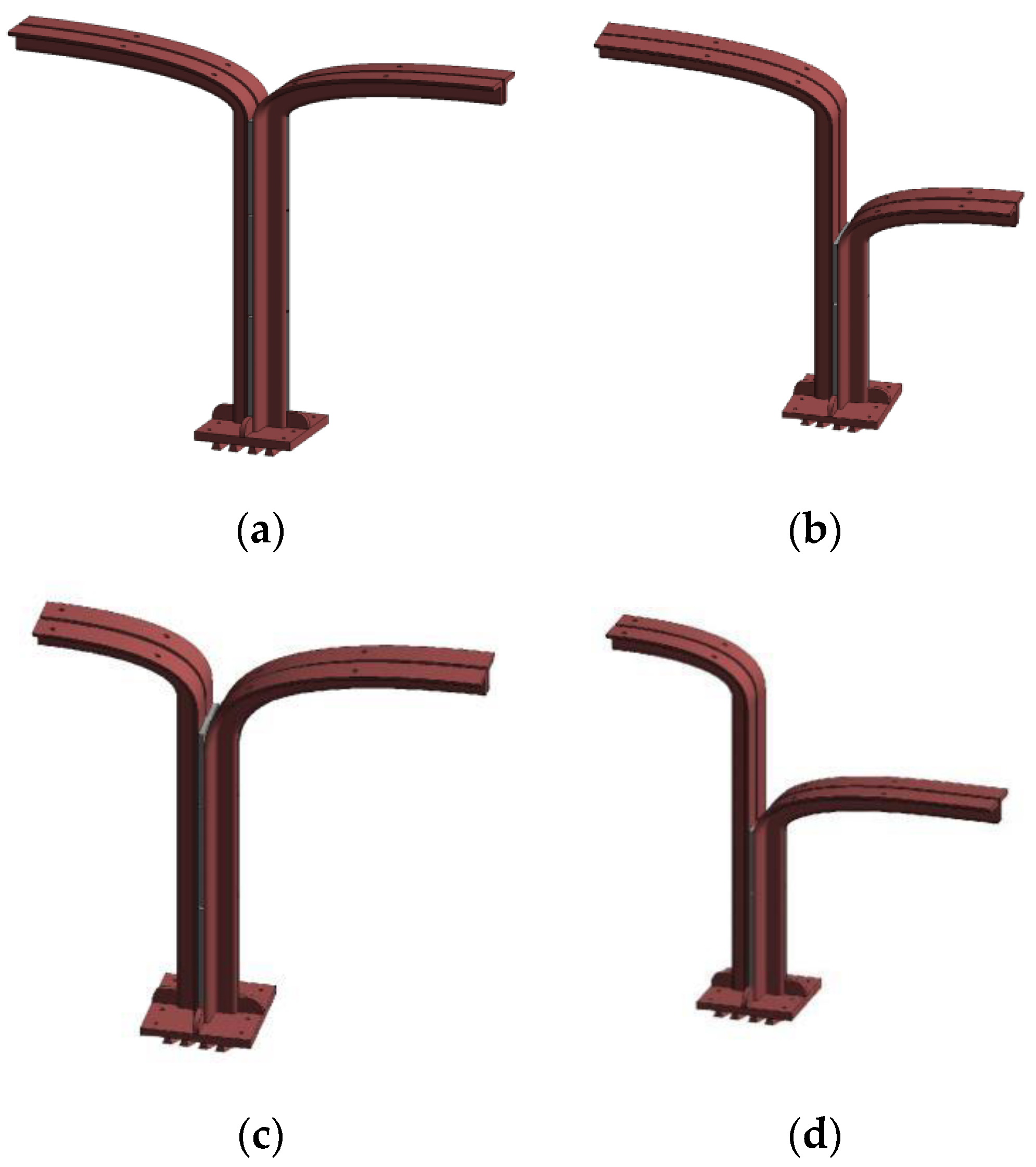
3.1. Superstructure of the Growable Light Steel Building

The superstructure of the growable light steel structure can be connected by the basic units to form a multi-span transverse rigid frame. Take a single steel frame formed by two standard units connected by a steel plate as an example of structural design, as shown in Figure 10a. The steel frame is 4.5 m high, the overhang cantilever side span is 3.6 m, and the middle span is 7.2 m. In Figure 10b,c, the rigid frame in this form presents reasonable stress distributions with small deformations and strong applicability.
Based on the parametric characteristics of the light steel units, reasonable parametric variations can be calculated and analysed in terms of a single frame. The values of the height and span of the frame constituted by various variable parametric units are shown in Table 1. By analysing the numerical simulation results, when the vertical unit load is applied to the rigid frame formed by the three types of units with variable parameters, appropriate parameter adjustment of height and span have little influence on the mechanical performance of the rigid frame, and the stress distributions are similar (Figure 11). The assembled structural frame can work in a safe and stable state.
Figure 12 shows the von Mises stress and deformation contours of three rigid frames with variable parameters, i.e., rigid frame with the same span, different heights and taller internal cantilevers, rigid frame with the same span, different heights and taller external cantilevers, and rigid frame with the same height, different spans and longer internal cantilevers. As shown in Figure 12, larger compressive stresses appeared on the columns and over the arches, while larger displacements appeared at both ends of the cantilever parts.

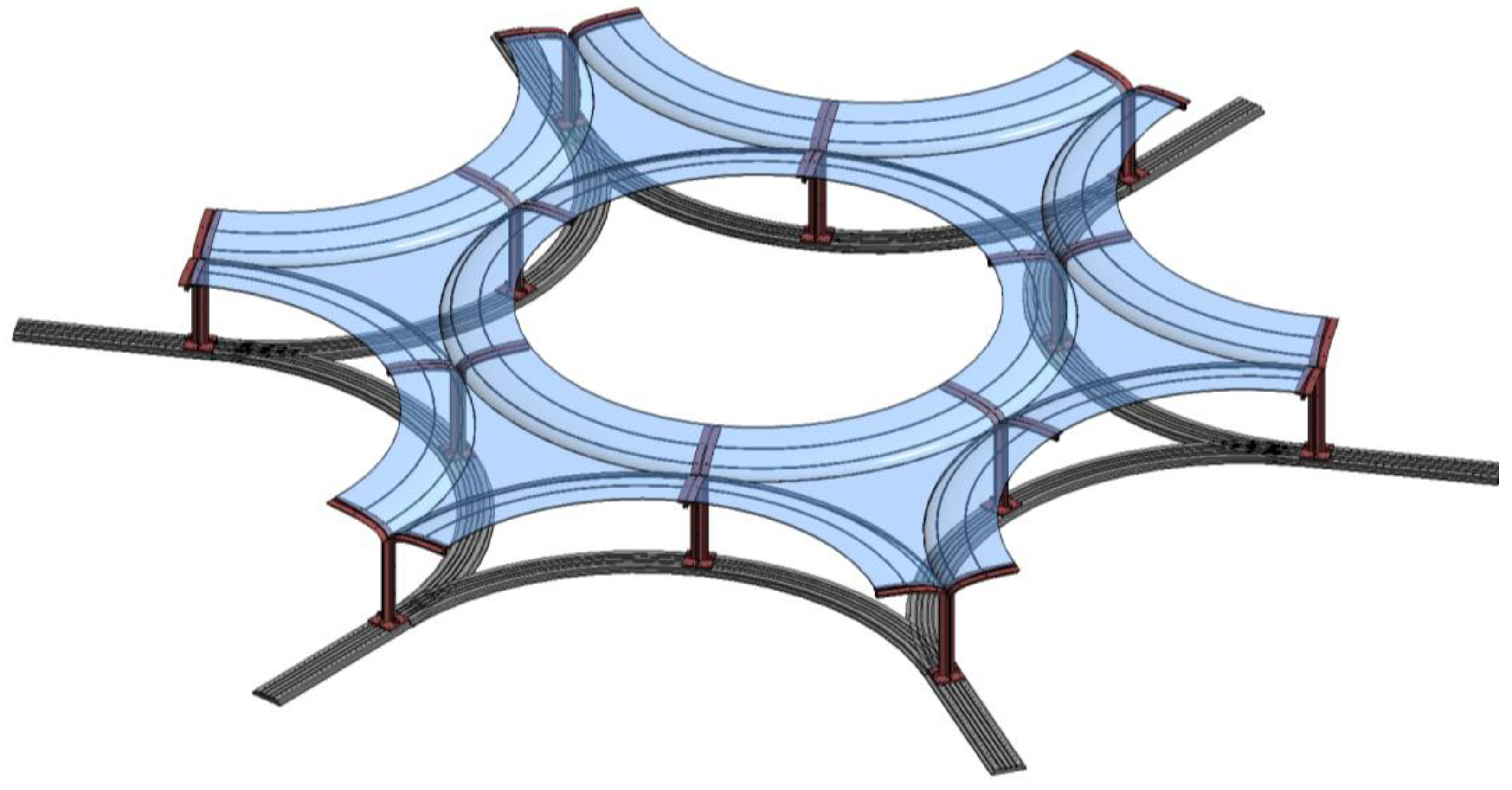
3.2. Foundation of the Growable Light Steel Structure

In view of the existing common reinforced concrete foundation, the construction process is relatively complicated and has a greater impact on the environment, in combination with the light steel structure itself, which has lightweight, uniform sections and fewer requirements for ground conditions and selected foundation. This study adopts a new track-type foundation supporting the growable light steel structure. As shown in Figure 13 and Figure 14, the two new types of foundations, which will be made of steel instead of the in situ concrete, can be prefabricated in the factory.
Two different forms of foundations proposed by our research group will be used for the foundations of the growable light steel structures. The basic unit is connected with mortise and tenon interlocks within the rail, and mechanical bolts with standard spacing bolt holes are reserved on the track and bottle panel. As shown in Figure 14, the foundation is aligned with the column foot. The rigid frame of the units can be moved to the positions required by the designers and be connected by bolts to strengthen the connections between the foundation and the superstructure and improve their ability to resist lateral loadings.
As shown in Figure 14, different from the first form of foundation, there are transmission rolls within the track. By activating the transmission rolls within the track, the rigid frame of the units can be moved to the positions required. The form of the foundation, shown in Figure 14, will provide a possible choice for the designer.
At the same time, the arrangement of the column foot has a high degree of flexibility. In other words, this operation realises the fast position of the structural units and free restrictions on the width and span variations between individual structural frames. It will be suitable for the light steel structure as a temporary building with the characteristics of being detachable and multiple recycling. The track-type foundation for the growable steel structure can be split by members. Therefore, the factory can prefabricate the transmission track and its matched column foot panels, which all can be quickly installed on the construction site. In this way, the construction process can be simplified, productivity can be greatly improved, and the rapid construction of the light steel structure can be truly realised.

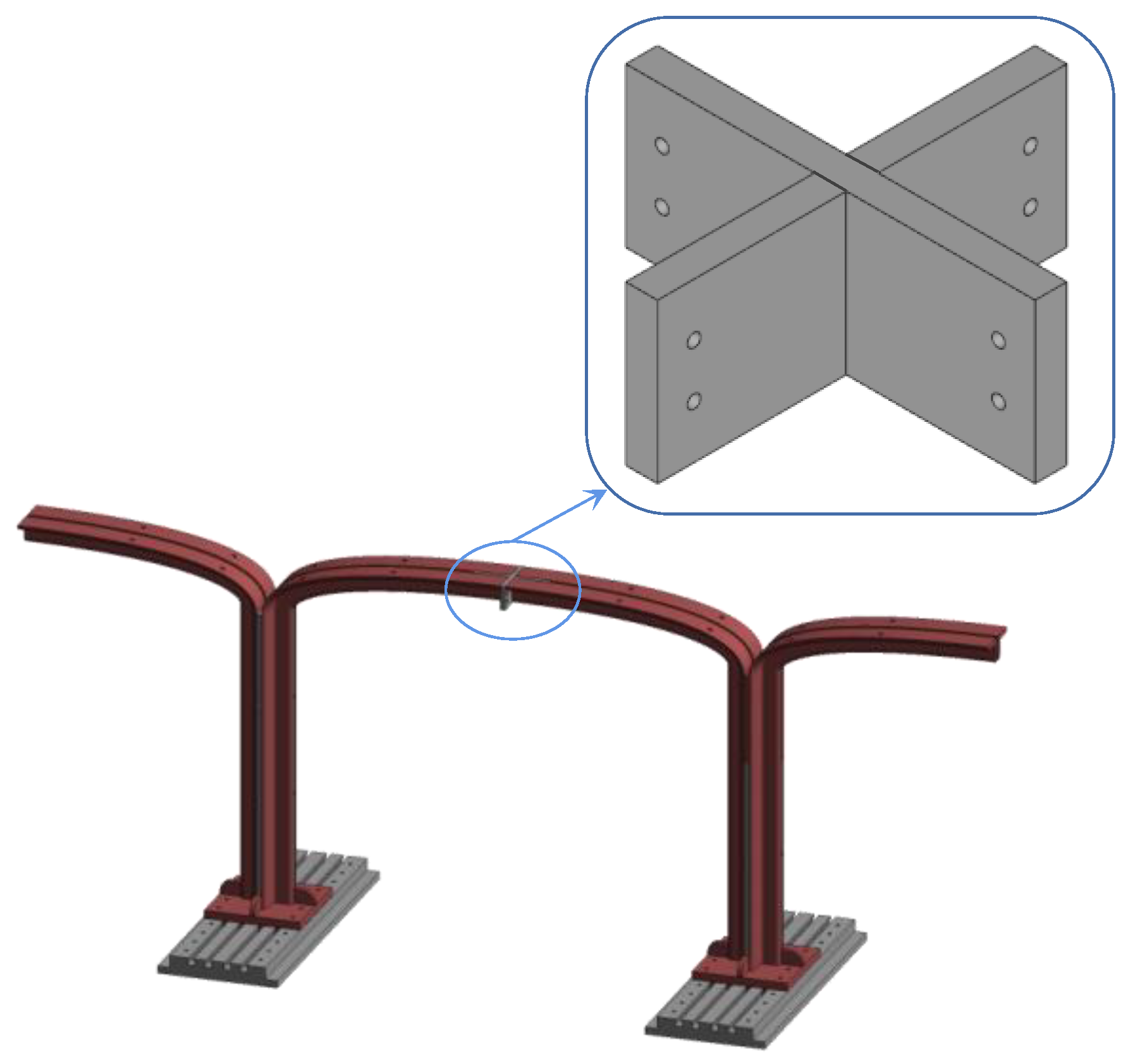
3.3. Braces and Connections

The connections between the units can significantly influence the behaviour and construction of the whole structure. The connecting rods, as shown in Figure 15, are assembled with three types of components. Prefabricated connecting rods can be installed with the distances between the units.
A cross-connector, as shown in Figure 16, is used to connect two basic units. The connecting plate parallel to the beam is used to connect the two T-sections, while a vertical connecting plate is used to connect the transverse horizontal braces at the midspan.

4. Expansions of the Architectural Form of the Diversified Growable Light Steel Units and Structures

Currently, urban land resources are limited while the development and expansion speeds are accelerated, and lightweight buildings and temporary buildings have almost no proportions in urban buildings [29]. How to highly utilise land resources, reduce the construction cycle, improve construction efficiency, enrich urban building types and forms, and at the same time put light steel structures into urban buildings and their supporting facilities to promote the integration of daily office, entertainment, and leisure life for urban residents will be an urgent problem to be solved. Based on the core idea of growable and parametric characteristics of the basic unit, reasonable layout, design, and combination of parametric structural units can greatly improve the overall environmental adaptability of structures and space utilisation rate and enrich the service function. The expanded architectural space forms are discussed as follows.

4.1. Linear Extension Space

The layout of a basic unit is presented in Figure 17, a new type of longitudinally and transversely extendable spatial structures which can be used for single-span and multi-span light steel industrial plants. It has the advantages of high assembly, industrialisation, environmental protection, and energy saving, and possesses the characteristics of good seismic performances of light steel structures and high space utilisation rates.

4.2. Single Central Space

The layout of a basic unit is shown in Figure 18. The basic unit used in the structure is of the unit types with the same span but different heights. The foundation track adopts the circular guide rail composed of straight-line and circular arc segments on both sides.
Each unit body on the straight track is transversely connected to form a rigid frame. Two external insertion units on the circular track are connected with the rigid frame cross plates at both ends of the straight track using bolts. The truss of each frame is connected with a tie rod, which is covered with roofing boards or films to form the final building entity. The main body of the building has a large single central space, which can be used as a large restaurant, customer reception, service centre, or temporary shelter to serve a large number of people and stay for a short time.

4.3. Transversely Centripetal Space

The layout of each basic unit is shown in Figure 19. The buildings adopt two types of basic units with the same span but different heights and different spans and different heights. The foundation track is composed of two concentric circular rails at certain intervals. The long-span semi-bodies of the two basic units are connected by a cross-shaped plate, where the short-span semi-bodies with the same height face the outside of the concentric circle track, and the half-bodies with different heights face the inside of the concentric circle track to form a frame with steel units.
Based on a steel frame, the final building can be formed by rotating symmetrical elements. The transversely centripetal space architecture has the beauty of both central and axial symmetry. Based on the parametric design and splicing of the units, the service space is adjusted to make the overall spatial structure well-proportioned and the functional partition clear. It can be applied to temporary stadiums or concert venues, etc., and the overall space utilisation and function divisions are efficient and complete.

4.4. Radiative Space

The layout of a basic unit is illustrated in Figure 20, which is composed of the type with the same height but different spans and the type with the standard unit. The two types of basic units have the same height. The base orbit consists of six circular orbits that are tangential to each other and symmetrical to the individual centres. The basic unit of the type with the same height but different spans has a long-span semi-body facing the interior of the hexagon centre, while the short-span semi-body is placed at the midpoint of the arc orbit. The standard units are placed at the end of the arc track, and the adjacent units are connected to the tie rods to form the overall building space. The building with radiative space is a regular hexagon geometry in a plane. The circular arc on each side satisfies any two adjacent arcs to be tangential to each other, making the overall track form have the aesthetic expressions of central symmetry and axial symmetry. This type of building can be applied to large-scale cultural, art exhibition halls, and historical relic museums because of its spatial aesthetic advantage and large covering space, to make the architectural structure form consistently with the use function.
The four above-mentioned architectural space forms are derived from the novel growable structures with steel units proposed in this study. In the practical design and construction process, designers can innovate and adjust the track-type foundation, connection joints and space layout based on the parameterisation of the new light steel units according to the requirements of different clients and building environments. In this way, the architectural forms of the new growable light steel structures can be enriched, and their development and utilisation can be promoted in practical projects.

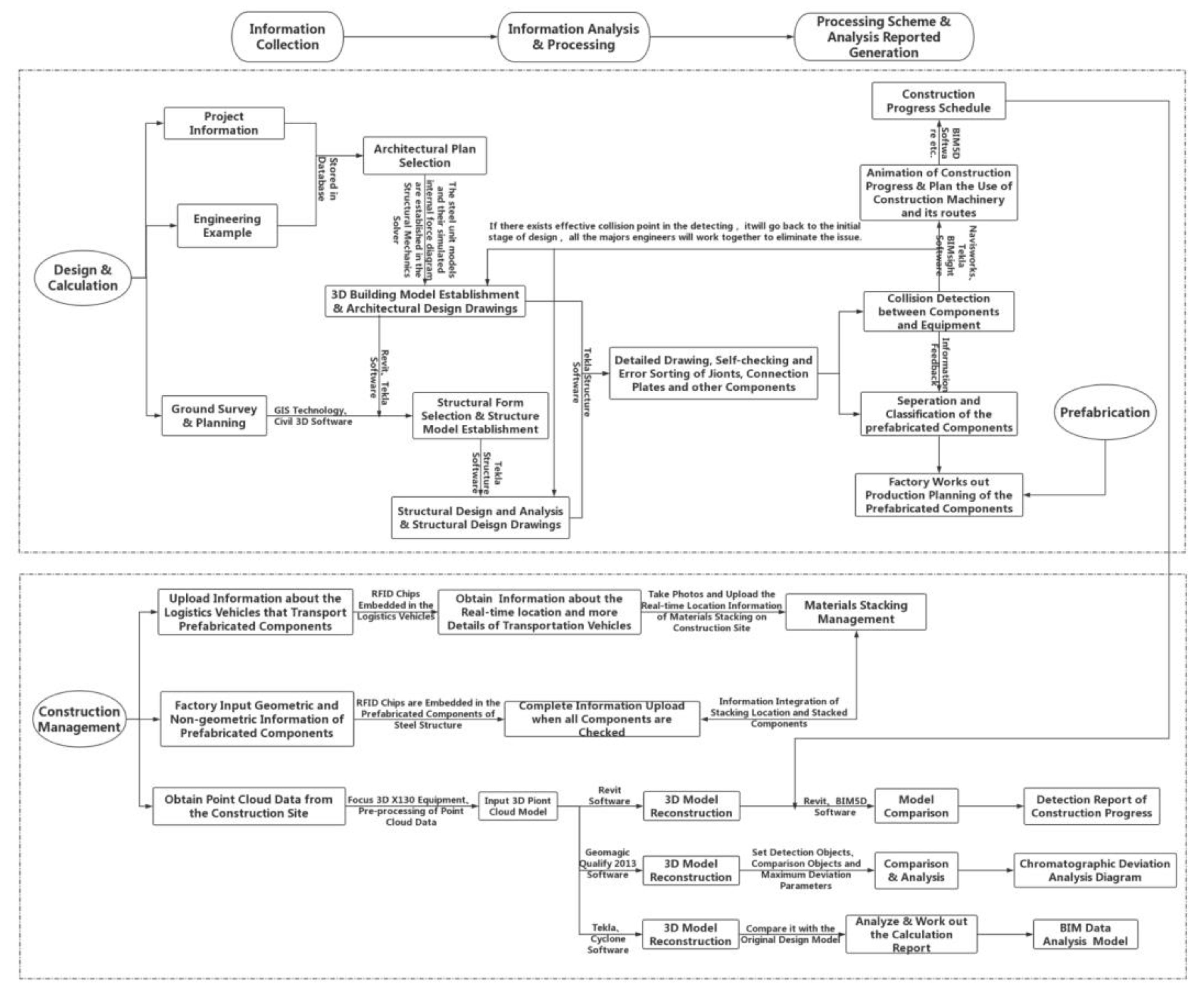
5. Design and Construction Method of the Growable Light Steel Structure Based on BIM Technology

By taking advantage of information sharing and 3D visualisation of BIM technology, the relevant information of the design and calculations, component prefabrications, and construction of the new type of growable light steel buildings can be systematically integrated to establish an informative BIM building model. It can realise 3D visualised information management of steel building structures from design to component production to site construction. In this study, the specific applications of the growable light steel building design and construction based on BIM technology mainly include design and calculations, prefabrications, and construction management. Additionally, each step contains various operations for information updating within the whole BIM-based system. With the advantage of highly integrated and interactive information and the forms of three-dimensional intuitive expressions, it can greatly improve the design, construction efficiency, and engineering economic benefits.
Step 1 Design and Calculations. Architectural Design includes project information, plan selection, and modeling. Project information is imported through the existing project data, which makes it easy for architects to review and refer to. An architectural designer can select the basic components of a unit in the Plan Selection option. BIM commercial modeling software packages, such as Revit and Tekla, which are embedded in the system platform, are used to model the initial architectural design forms and to output the architectural design and construction drawings. Structural Design is combined with site survey and planning, selections of growable structural forms, and structural analyses and calculations. Combining GIS technology and Civil 3D BIM software, the complex site geographic information data are imported into Civil 3D for analyses and calculations, and the system automatically establishes the route model. MIDAS or other structural analysis software packages are used to simulate and calculate all common structural forms and their mechanical characteristics so that the structural engineer can choose useful structural forms according to the demands. The structural analysis calculation option adopts Tekla Structures software to build the 3D structure model, and the software automatically analyses the structure model to generate the structural analysis calculation book.
Step 2 Prefabrications. Prefabrications include detailed design, information on component divisions, the prefabrication process of components, and construction schedules determined by construction simulations. The detailed design option is generally based on the hardware of the graphic workstation, which can be realised by Tekla Structure, Revit, or other BIM commercial software packages. After the structural design is revised and corrected, detailed construction drawings and component processing information can be obtained. RFID technology will be introduced in the component prefabrication process by inserting chips into the component. The embedded RFID chips will be input with the component serials, project codes, material attributes, location codes, expansion areas, and other detailed component information. Combined with BIM software packages such as Revit, the processing information of components can be monitored in real-time to strictly control the quality of components. The factory can also create the standard library of precast components [30] in advance to store detailed information on the components, which can not only serve as the reference for the architectural design of the growable structures with light steel units but also provide data support for the subsequent component resolutions to improve the design and precast processing efficiency.
Step 3 Construction Management. Navisworks and Tekla BIM Sight software packages are adopted to realise collision detection in the construction process simulations. In other words, the construction process of the light steel unit structure is demonstrated in advance to avoid the rework problem in practical construction and provide a basis for determining the construction schedules. Construction Process Management is to adopt automatic and integrated means to plan and manage the transportation, acceptance, and stacking of prefabricated components and to realise intelligent monitoring of progress and quality control in the construction process. The material management option makes use of RFID technology, with the chips inserted in the prefabricated components as well as the transportation vehicles. Based on the system platform, data input and feedback are continuously carried out when components leave out of a factory, truck transportation, component acceptance, and material stacking on site to realise the efficient management of materials. The progress management option utilises 3D laser scanning technology to scan the construction site and obtain the point cloud data. After the pre-processing of the point cloud data, the point cloud model is imported into Revit, Tekla, or other commercial BIM application software to achieve 3D model reconstruction and compare the simulated construction schedule to clearly understand the current construction schedule information. Construction quality inspection is to inspect and supervise the construction process of the main prefabricated steel structure. The 3D laser scanning technology is still used to establish the 3D model of the practical structure by fitting the original BIM design model to conduct the analysis of the vertical displacement of the fabricated steel structure [31]. During this process, the model fitting and bias analysis will be implemented by the Geomagic Qualify detection software [32].
To sum up, as the project progresses, the implementation process of 3D visualisation design and construction method takes the order of information collection, information analysis and processing, and processing scheme and analysis report generation. The three implementation procedures illustrate the main idea of the whole system. With the help of GIS, RFID, and other external technologies, data information acquisition in the early stage is carried out. Besides, relevant data model establishment and information storage are realised in each BIM application software package embedded in the system. Finally, the system and related external software promote the completion of information analysis and processing. The detailed implementation process of the design and construction of the growable steel-unit structure is shown in Figure 21.
Based on the proposed implementation process of BIM, linear extension space building is analysed as a case, and the case is realised in four steps, as shown in Figure 22: architectural plan selection, structural design, calculations, and construction management. 1: new construction and construction management; 2: building space adjustment.

6. Conclusions

Combining three factors, i.e., environment, structural space design, and service function, new types of growable light steel-unit structures are proposed. By virtue of the building design and construction method integrated with BIM technology, the diverse architectural formations of the growing light steel unit structures can be realised. Based on this study, the following conclusions can be drawn:
  • The basic units of light steel structures are proposed, and their good mechanical properties are analysed and verified. The three characteristics of the basic units of growing-type light steel structures, namely utilised, parametric, and assembled, are analysed. Based on the parametric design, reasonable layout of structural units, and practical construction assembly, the diverse growth of light steel-unit structures can be realised;
  • To adapt to the growable light steel-unit structures, new track-type foundations are adopted, which not only bear and transfer the loadings from the upper light steel-unit structure but also promote the arrangement of the positions of light steel units through mechanical transmission. The track-type foundations can be divided into individual components. The transmission rails and supporting column foot panels can be prefabricated, which realises the integration of the building construction industry, mechanical engineering, and environmental protection, and reduces the damage to the construction site environment. It can also be recycled for energy saving and efficiency, further promoting the industrialisation and automation process;
  • Based on the characteristics of the growable light steel-unit structures, combined with the changes in the form of the basic tracks, the extension and contraction of the architectural space are realised, the structural form and service space are adjusted, the secondary reorganisation and optimisation of the structural space are completed, and the architectural forms with various service spaces are further expanded. This study explores the application of growability in new light steel structure buildings, which shows great advantages and potential in various aspects, such as enriching the use function of the building, making efficient use of site resources, and improving the utilisation rate of structural space;
  • Finally, this study explores the implementation method of the design and construction of growable light steel buildings based on BIM technology, systematically analyses the relevant information among the design calculations, component prefabrications, and construction process of the new growable light steel buildings, and executes the operations required in individual stages. By using highly integrated information interaction and 3D visual expression form, the design, construction efficiency, and project benefits of steel buildings are greatly improved.
In the future, the structural scheme of the growable light steel structure is to be explored. With the dynamically variable building demands, the details of the drawings and whole model analyses are to be completed in the follow-up study.

Author Contributions

Conceptualization, H.J., Z.L., B.Z., Y.S. and X.Z.; Data curation, H.J., Z.L. and B.Z.; Funding acquisition, H.J., Z.L., B.Z., Y.S. and X.Z.; Investigation, H.J., Z.L., B.Z. and X.Z.; Methodology, H.J., B.Z. and Y.S.; Resources, H.J., Y.S. and X.Z.; Software, H.J., Z.L. and Y.S.; Supervision, H.J., Z.L. and Y.S.; Validation, H.J., B.Z. and Y.S.; Visualization, H.J. and B.Z.; Writing—original draft, H.J., Z.L. and B.Z.; Writing—review & editing, H.J. and B.Z. All authors have read and agreed to the published version of the manuscript.

Funding

This research was funded by the Jiangsu Natural Science Foundation with Grant No. BK20211003, the Project of the Six Talent Peaks in Jiangsu Province with Grant No. jz-062, the Natural Science Fund for Colleges and Universities in Jiangsu Province with Grant No. 17KJB560004, the Jinling Institute of Technology High-Level Personnel Work Activation Fee to Fund Projects with Grant No. jit-b-201614, the Jinling Institute of Technology High-level Personnel Work Activation Fee to Fund Projects with Grant No. jit-b-201608 and the Program of National Natural Science Foundation No. 51608103.

Data Availability Statement

The data used to support the findings of this study are included within the article.

Acknowledgments

This project is supported by Department of Civil Engineering in the School of Architectural Engineering at Jinling Institute of Technology in Jiangsu Province, China, Nanjing Metro Group Co. Ltd. in Jiangsu Province, China, and the School of Computing, Engineering and Built Environment at Glasgow Caledonian University, Scotland, UK.

Conflicts of Interest

The authors declare that there is no conflict of interest regarding the publication of this paper.

References

  1. Li, S.; Deng, K. Lightweight reconfigurable structure system (LRSS): Rethinking temporary buildings. In Proceedings of the Eco-Architecture 2018, New Forest, UK, 2–4 October 2018; Available online: https://www.wessex.ac.uk/conferences/2018/eco-architecture-2018 (accessed on 28 July 2020).
  2. Li, H.; Lin, J.; Lian, H.; Chen, K.; Lyu, Y.; Chen, Y.; Ren, L.; Zheng, L.; Lin, Z.; Yu, X.; et al. The Performance of Mobile Cabin Hospital in Combatting COVID-19 in China. 2020. Available online: https://search.bvsalud.org/global-literature-on-novel-coronavirus-2019-ncov/resource/en/ppmedrxiv-20162206 (accessed on 28 July 2020).
  3. Chen, D.; Wang, G.; Chen, G. Lego architecture: Research on a temporary building design method for post-disaster emergency. Front. Archit. Res. 2021, 10, 758–770. [Google Scholar] [CrossRef]
  4. Kronenburg, R.; Lim, R.; Chii, W.Y. Transportable Environments; Taylor & Francis: London, UK, 2003. [Google Scholar]
  5. Hosseini, S.M.A.; Farahzadi, L.; Pons, O. Assessing the sustainability index of different post-disaster temporary housing unit configuration types. J. Build. Eng. 2021, 42, 102806. [Google Scholar] [CrossRef]
  6. Yun, B.Y.; Kang, Y.; Kim, U.Y.; Wi, S.; Kim, S. Practical solutions with PCM for providing thermal stability of temporary house, school and hospital in disaster situations. Build. Environ. 2022, 207, 108540. [Google Scholar] [CrossRef] [PubMed]
  7. Yang, S.; Wi, S.; Cho, M.H.; Park, J.H.; Yun, Y.B.; Kim, S. Developing energy-efficient temporary houses for sustainable urban regeneration: Manufacturing homes with loess, pearlite, and vermiculite. Sustain. Cities Soc. 2020, 61, 102287. [Google Scholar] [CrossRef]
  8. Grosso, M.; Thiebat, F. Life cycle environmental assessment of temporary building constructions. Energy Procedia 2015, 78, 3180–3185. [Google Scholar] [CrossRef] [Green Version]
  9. Zhu, L.; Yang, Y.; Chen, S.; Sun, Y. Numerical study on the thermal performance of lightweight temporary building integrated with phase change materials. Appl. Therm. Eng. 2018, 138, 35–47. [Google Scholar] [CrossRef]
  10. Zheng, P.; Wu, H.; Liu, Y.; Ding, Y.; Yang, L. Thermal comfort in temporary buildings: A review. Build. Environ. 2022, 221, 109262. [Google Scholar] [CrossRef]
  11. Ye, R.; Wang, J.; Jiang, H.; Xie, N. Numerical study on thermal comfort and energy-saving potential of a prefabricated temporary house integrated with composite phase change materials. Energy Build. 2022, 268, 112169. [Google Scholar] [CrossRef]
  12. Köhler, D. The Mereological City: A Reading of the Works of Ludwig Hilberseimer; Transcript: Bielefeld, Germany, 2016. [Google Scholar]
  13. Wang, L. Study on Operation Performance of Green Public Buildings in Dalian Affected by Epidemic Situation. Master’s Thesis, Dalian University of Technology, Dalian, China, 2021. [Google Scholar]
  14. He, L.; Zhang, L. A bi-objective optimization of energy consumption and investment cost for public building envelope design based on the E-constraint method. Energy Build. 2022, 266, 112133. [Google Scholar] [CrossRef]
  15. Guo, C.; Bian, C.; Liu, Q.; You, Y.; Li, S.; Wang, L. A new method of evaluating energy efficiency of public buildings in China. J. Build. Eng. 2022, 46, 103776. [Google Scholar] [CrossRef]
  16. BCA Committee. Design for Manufacturing and Assembly (DfMA): Prefabricated Prefinished Volumetric Construction; Building and Construction Authority (BCA): Singapore, 2020.
  17. Aziz, S.; Nasir, S.N.C.M.; Hatrom, R.; Bazuli, L.A.; Abdullah, M.R. Modular construction system (MCS) in Malaysia: Mass customization through combinatorial. IOP Conf. Ser. Earth Environ. Sci. 2019, 385, 012030. [Google Scholar] [CrossRef]
  18. Xu, Z.; Zayed, T.; Niu, Y. Comparative analysis of modular construction practices in mainland China, Hong Kong and Singapore. J. Clean. Prod. 2020, 245, 118861. [Google Scholar] [CrossRef]
  19. Lyu, Y.-F.; Li, G.-Q.; Cao, K.; Zhai, S.-Y.; Li, H.; Chen, C.; Wang, Y.-Z. Behavior of splice connection during transfer of vertical load in full-scale corner-supported modular building. Eng. Struct. 2021, 230, 111698. [Google Scholar] [CrossRef]
  20. Lyu, Y.-F.; Li, G.-Q.; Cao, K.; Zhai, S.-Y.; Wang, Y.-B.; Mao, L.; Ran, M.-M. Bending behavior of splice connection for corner-supported steel modular buildings. Eng. Struct. 2022, 250, 113460. [Google Scholar] [CrossRef]
  21. Zhai, S.-Y.; Lyu, Y.-F.; Cao, K.; Li, G.-Q.; Wang, W.-Y.; Chen, C. Experimental study on bolted-cover plate corner connections for column-supported modular steel buildings. J. Constr. Steel Res. 2022, 189, 107060. [Google Scholar] [CrossRef]
  22. Zhou, Y. Research on growable and changable educational buildings: A conceptual design of reconstruction of educational buildings after disaster. Ind. Constr. 2020, 40, 36–38. [Google Scholar]
  23. Graziano, A.; Bettucci, E. Growing Architecture: Iterative Growth and Cells Differentiation. 2022. Available online: https://www.iaacblog.com/programs/growing-architecture-syllabus-faculty/ (accessed on 5 April 2022).
  24. Angeletou, K. Modifiable Public Space: A System of Public Movable Structures to Enable Space Customization by the User. 2018. Available online: https://futurearchitectureplatform.org/projects/50411ca0-5b32-4a67-8ac1-52b6cd65d253/ (accessed on 5 April 2022).
  25. Song, F.; Chen, H. Sustainable utilization of detachable building. Des. Technol. 2018, 2, 17–24. [Google Scholar] [CrossRef]
  26. Peng, Z. Temporary Building’s Design Method Research Based on Rapid Construction. Master’s Thesis, Xi’an University of Architecture and Technology, Xi’an, China, 2015. [Google Scholar]
  27. Yan, H.; Luo, D. Discuss on demountable building. Hous. Sci. 2015, 35, 24–28. [Google Scholar] [CrossRef]
  28. Jia, Y. Research on the Newbud LGS System and Geometric Evolution. Master’s Thesis, Xi’an University of Architecture and Technology, Xi’an, China, 2012. [Google Scholar]
  29. Cao, Y. The Function and Research Value of Temporary Landscape in Urban Public Space. Ph.D. Thesis, Shanghai University, Shanghai, China, 2019. [Google Scholar]
  30. Wu, S.; Wang, L.; Han, S. Application of BIM technology in design and construction of multi-storey fabricated steel structure residential buildings. Build. Constr. 2019, 41, 691–693. [Google Scholar] [CrossRef]
  31. Yao, X.; Chen, H.; Jia, S.; Zhao, W. Application of 3D laser scanning and BIM technology in deformation monitoring of super high-rise steel structure. Ind. Constr. 2019, 49, 189–193. [Google Scholar] [CrossRef]
  32. Xie, H. The Application Research of 3D Laser Scanning Technology on Architecture Field. Master’s Thesis, Hefei University of Technology, Hefei, China, 2017. [Google Scholar]
Figure 1. (a) Temporary hospital units in Seoul Medical Centre, Korea. (b) Schematic diagrams of box experiments on the thermal properties of PCMs. Reprinted with permission from Ref. [6] ©2021, Elsevier Ltd.
Buildings 12 02041 g001
Figure 2. (a) 3D effect diagram of a proposed SUP structural unit and (b) its final physical construction result. Reprinted with permission from Ref. [3] ©2021, Chen*, Wang and Chen.
Buildings 12 02041 g002
Figure 3. Reinforced concrete and steel PPVC modules of Wisteria, an engineering case in Singapore. Reprinted with permission from Ref. [18] ©2019, Elsevier Ltd.
Buildings 12 02041 g003
Figure 4. Adopted modular building and module [19]. Reprinted with permission from Ref. [19] ©2020, Elsevier Ltd.
Buildings 12 02041 g004
Figure 5. The splice connections [20]. Reprinted with permission from Ref. [20] ©2021, Elsevier Ltd.
Buildings 12 02041 g005
Figure 6. Illustration of a movable structural unit and its application in a given public space [24].
Buildings 12 02041 g006
Figure 7. Basic unit of the growable light steel structure.
Buildings 12 02041 g007
Figure 8. Von Mises stress and deformation contours of the basic unit under vertical loadings.
Buildings 12 02041 g008
Figure 9. Two new forms of basic unit sections. (a) basic unit with a biaxial symmetrical I-section; (b) basic unit with a monosymmetrical I-section.
Buildings 12 02041 g009
Figure 10. Parameterised units of different configurations. (a) Standard unit; (b) Unit with the same span but different heights; (c) Unit with the same height but different spans; (d) Unit with different heights and spans.
Buildings 12 02041 g010
Figure 11. Schematic diagram and mechanical analysis of a single steel frame formed by two standard units and connected by a steel plate. (a) Schematic diagram; (b) Stress distribution under the vertical load; (c) Deformation under the vertical load.
Buildings 12 02041 g011
Figure 12. Stress distributions and displacement results of three rigid frames with variable parameters. (a) Rigid frame with the same span, different heights, and taller internal cantilevers; (b) Rigid frame with the same span, different heights, and taller external cantilevers; (c) Rigid frame with the same height, different spans, and longer internal cantilevers.
Buildings 12 02041 g012
Figure 13. Schematic diagram of the mortise-tenon foundation and its connection.
Buildings 12 02041 g013
Figure 14. Schematic diagram of the mechanical track-type foundation and its connection.
Buildings 12 02041 g014
Figure 15. Prefabricated connecting rods.
Buildings 12 02041 g015
Figure 16. Details of the cross connector between two basic units.
Buildings 12 02041 g016
Figure 17. Spatial form of a linearly extended basic unit.
Buildings 12 02041 g017
Figure 18. Spatial form of a single central building.
Buildings 12 02041 g018
Figure 19. Spatial form of a transverse centripetal building.
Buildings 12 02041 g019
Figure 20. Spatial form of a radiative building.
Buildings 12 02041 g020
Figure 21. Implementation process of the design and construction method of the growable steel-unit structures.
Buildings 12 02041 g021
Figure 22. The realization process of the linear extension space building.
Buildings 12 02041 g022aBuildings 12 02041 g022b
Table 1. Types and related parameters of the units with variable parameters.
Types of Parameter VariationHeight of Middle Span (m)Height of Side Span (m)Span of Middle Span (m)Span of Side Span
(m)
Different heights of the same span
(Internal cantilevers are taller)
64.57.23.6
Different heights of the same span
(External cantilevers are taller)
4.56.07.23.6
Different spans of the same height
(Internal cantilevers are longer)
4.54.59.03.6
Publisher’s Note: MDPI stays neutral with regard to jurisdictional claims in published maps and institutional affiliations.

