Article

Effects of Wall-to-Wall Supported Ceilings on Impact Sound Insulation for Use in Residential Buildings

1
Department of Architectural Engineering, University of Seoul, Seoulsiripdae-ro 163, Dongdaemun-gu, Seoul 02504, Korea
2
Architecture Research Group, Posco E&C, Incheon Tower-Daero, Yeonsu-gu, Incheon 22009, Korea
*
Author to whom correspondence should be addressed.
Buildings 2021, 11(12), 587; https://doi.org/10.3390/buildings11120587
Submission received: 6 October 2021 / Revised: 18 November 2021 / Accepted: 23 November 2021 / Published: 26 November 2021
(This article belongs to the Section Building Structures)

Abstract

:
In Korean residential buildings, floor impact sounds were reduced over the past few decades mainly through a floating floor system. However, ceiling constructions for impact sound reduction have not been applied actively because of a lack of useful information. This study focuses on the effects of wall-to-wall supported ceilings (WSC), which are designed with construction discontinuities between concrete slabs and ceilings, and the damping caused by porous absorbers for impact sound insulation. To examine the impact sound insulation according to ceiling conditions, measurements were performed in 25 floor–ceiling assemblies. The results indicate that ceiling treatment is mostly useful in reducing the floor impact sound. The floor impact sound owing to the WSC decreased by 2–7 dB and 2–8 dB in terms of the single number quantity for the tapping machine and rubber balls, respectively, compared with representative existing housing constructions wherein ceilings were attached on wooden sticks. Furthermore, the reduction effect of the WSC appeared to be more profound when it was applied to the floor–ceiling assembly with poor impact sound insulation. Thus, the WSC can be used to enhance the impact of sound insulation of existing housings without major repairs of floor structural layers.

1. Introduction

Floor impact sounds, such as walker footsteps, constitute one of the major complaints of apartment residents in various countries, including South Korea and European countries [1,2]. In South Korea, more than 60% of residents live in apartments and walk barefoot; hence, footstep noise or children’s running noise is frequently generated. As these noise types are a major reason for neighborhood conflicts, the South Korean government recommended a thicknesses of at least 210 mm for concrete slabs and imposed legal requirements in terms of impact sound insulation since 2005. Subsequently, various impact sound reduction techniques were considered in newly built apartments [3,4,5]. However, the apartments that were already built before enacting the minimum performance standards (hereinafter referred to as existing housing) account for 80% of the total apartments and have poor impact sound insulation performance. Therefore, issues regarding the impact sounds in existing housing remain unresolved. To this end, an impact sound reduction technique needs to be developed for existing housing through renovation; in particular, a facile method of renovation is necessary to reduce the time and cost involved in reducing impact sounds.
In South Korea, owing to the characteristics of the floor heating system with multilayer materials, various studies investigated floating floors and resilient materials [6,7]. A floating system with a resilient material is well known to be an effective construction for reducing the impact noise, and the acoustic performance of resilient materials has been actively studied [7,8,9,10,11]. In particular, resilient materials with low-dynamic stiffness were reported to be effective in reducing impact sounds [7]. Recently, Caniato et al. [11] showed that the static load over time has a paramount influence on resilient material and its final performance.
Even though floating floors represent a key method for reducing impact noise, suspended ceilings or structural discontinuities can be utilized to improve the impact sound insulation performance [12,13]. A few studies examined the impact sound insulation performance of suspended ceilings at the bottom parts of floor structures [14,15,16,17,18,19,20,21]. In these studies, the effects of the suspended ceilings on the impact sound insulation performance varied depending on the experimental conditions. Kim et al. [14] measured the effects of suspended ceilings on heavyweight impact sound. The ceiling was installed in a rectangular-shaped room with 210 mm-thick concrete slabs and a floating floor system. The results showed that the impact sound insulation owing to the air cavity depths in the range of 70–300 mm between the concrete base slab and drywall finish was not significant. Furthermore, according to the installation of a sound-absorbing material inside the air cavity, the impact sound insulation was not significant, and the impact sound level increased at a low-octave band (at a frequency of 63 Hz).
Ryu et al. [15] investigated the effects of a suspended ceiling in which a low-frequency resonant panel absorber was installed in the cavity. The heavyweight impact sound by the resonance panel absorber was reduced by 2 dB and 4 dB in terms of the single number quantity ( L i , F m a x , A w ) of KS F 2863-2 for the bang machine and rubber ball, respectively. These results were obtained from a rectangular room with dimensions 4.7 m × 5.3 m × 2.7 m, which was constructed with bare concrete slabs with thicknesses of 180 mm. Shin et al. [16] used a suspended ceiling with a perforated panel and porous absorbers and reported SNQ ( L i , F m a x , A w ) reductions of 1 dB and 2 dB for a bang machine and rubber ball, respectively. These results were obtained from a suspended ceiling installed at the bottom of the floating floor structures. Bettarello et al. [17] showed the influence on impact noise reduction by the floating floor and suspended ceiling on a building featuring a Cross Laminated Timber floor. The findings indicated that impact noise reductions offered by the suspended ceiling and floating floor were very similar for the tapping machine, while the suspended ceiling acted better than the floating floor for the ISO rubber ball, especially at low frequencies.
Some studies investigated the effects of the ceiling on the lightweight impact sound produced by the tapping machine. Souza et al. [18] studied some cases of impact sound pressure levels for one-way rib and hollow brick slabs using gypsum ceilings with air cavities (150 mm) and resilient layers (thickness equal to 10 mm). The results showed that the weighted values ( L n , A w ) for standard tapping machines were decreased from 13 dB to 16 dB by installing the gypsum ceiling. Meanwhile, Sipari [19] reported that the impact sound insulation effect of a resilient ceiling was observed at 50 Hz by a tapping machine. However, at frequencies below the 50 Hz band, wherein the footfall noise dominates, the resilient ceiling structure degraded the impact sound insulation properties. Huang [20] discussed the floor impact insulations of different floor systems and ceiling treatments. He emphasized that builders and apartment owners must consider floor impact insulation materials and ceiling construction treatments to minimize the impact noise in apartments at lower floors. Hui and Ng [21] proposed a new design concept for a floating ceiling with a special arrangement of stiffener beams and isolators to improve the vibration isolation performance. The proposed floating ceiling achieved a vibration reduction of 20 dB in the low-frequency range of 40–100 Hz. However, as the dimensions of the wooden panel in the field test are different from those of a real ceiling panel in a building, the application for usage in real apartment buildings is limited.
As a means for improving the impact sound insulation performance, the suspended ceiling is not as effective as the floor construction system. Thus, acoustic treatments on ceilings were not applied actively. However, the ceiling technique can use one of the methods to improve impact sound insulation. In particular, for the existing housing wherein the reinforcement of the impact sound insulation performance is required, the ceiling technique can be utilized as an effective construction method in terms of the time and cost advantages involved in reducing impact sounds.
According to previous studies, the reductions of impact sound due to ceiling treatment varied. The impact sound insulation performance depends on the design of ceiling systems as well as on the floor structures of a building. Therefore, empirical data on impact sound insulation using ceiling systems are required in the early design stage. In particular, the combined effect of floor–ceiling assemblies on impact sound insulation is rarely reported in comparison with the effect of floor structures, including resilient materials.
This study concentrates on the effects of the wall-to-wall supported ceiling, which is a new design concept formulated to reduce the impact sound in apartment buildings. The wall-to-wall supported ceiling and conventional ceilings were selected to compare the impact sound insulation responses. Measurements were performed in 25 floor–ceiling assemblies in four test rooms and three mock-up apartment buildings. The SNQ ratings of the 25 cases for lightweight and heavyweight impact sound insulation measured using a standardized tapping machine and a rubber ball were respectively reviewed and compared.

2. Experimental Methods

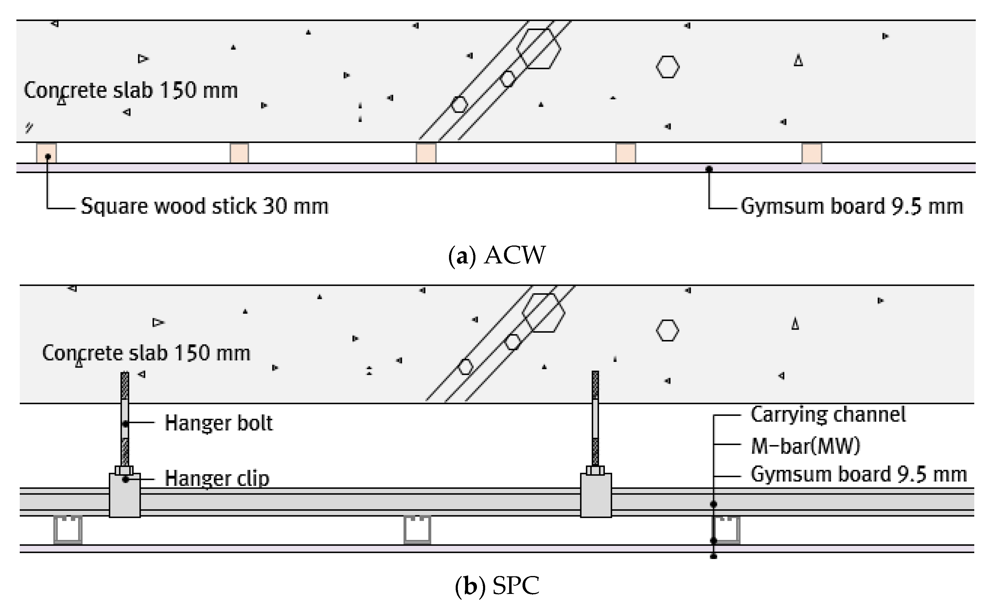
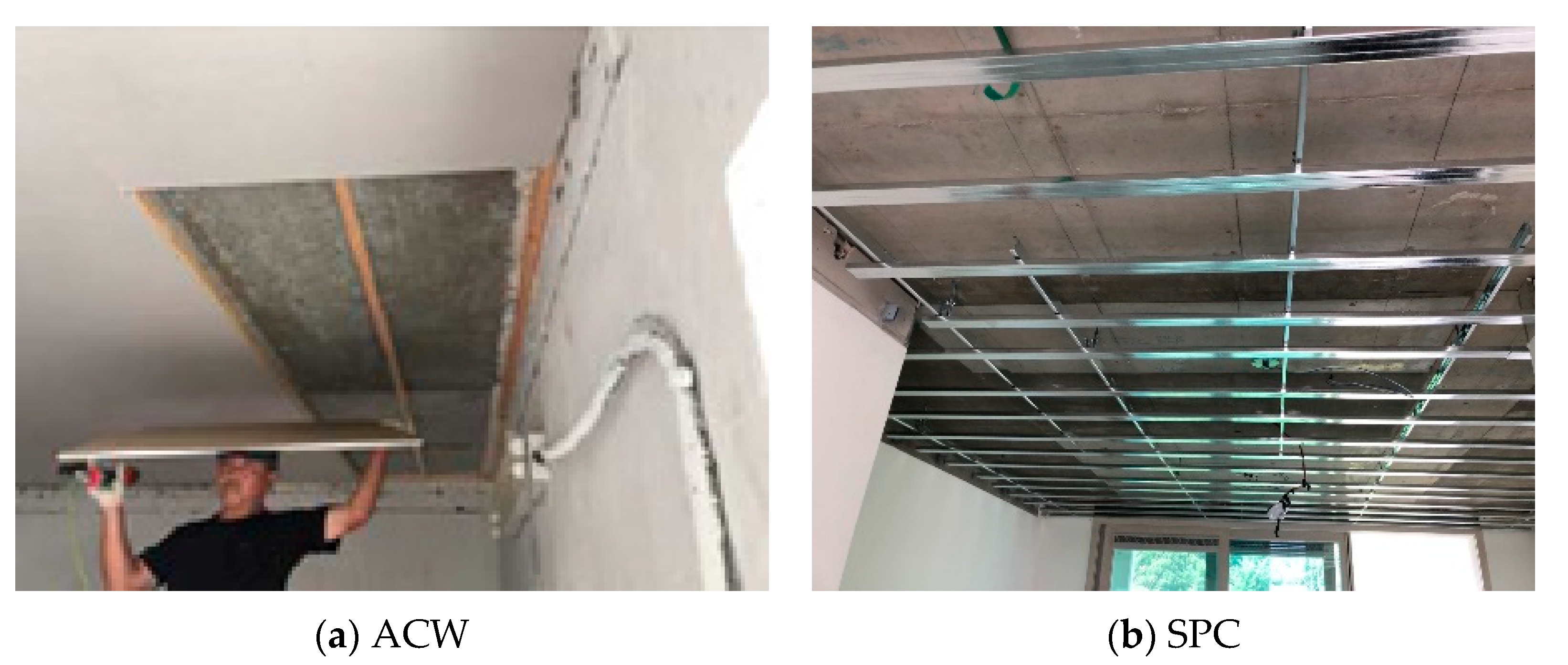
2.1. Ceiling Structures

The ceiling structures of Korean apartments were installed at the bottom parts of the concrete slab. In general, the plasterboard, which is a finishing material, was connected directly to concrete slabs with square wooden sticks or suspended grid channels. Recently, in Korean apartments, pipes, ducts, and lighting systems were installed inside the ceiling cavity; hence, ceiling structures are essential to screen these equipment types for clean finishing. To this end, in this study, we reviewed the effects of floor impact sound insulation using ceiling structures based on the use of two conventional ceiling structures used in South Korea as well as wall-to-wall supported ceiling structures developed for the reduction of floor impact sounds.

2.1.1. Conventional Ceiling Structure

Figure 1a,b show the two cross-sectional diagrams of the ceiling structures that are the most universally constructed in South Korean apartments. Figure 1a shows the attached ceiling on a square wooden stick (hereinafter denoted as “ACW”). The ACW structure can be often found in apartments built from the late 1980s to the 2000s in South Korea. It is the most typically used ceiling structure of the existing housing units built before the enactment of the legal requirements of impact sound insulation since 2005. Figure 1b shows the suspended ceiling (hereinafter, denoted as “SPC”) mostly used in newly built apartments. It is a suspension metal system composed of a m-bar of galvanized sheet iron and a carrying channel. It suspends the load of the ceiling by being directly connected to the concrete slab via a hanger. To conform with the new legal requirements for fire piping, sprinkler systems, and ventilation duct systems, an air cavity depth in the range of 150–200 mm is employed between the concrete slab and plasterboard, as adopted in newly constructed apartments.
These conventional ceiling structures have a structural shape in which the ceiling structure is directly connected to the bottom of the concrete slab with square wood sticks or hanger bolts; thus, they are vulnerable to impact sound insulation. Two types of conventional ceiling structures are shown in Figure 2.

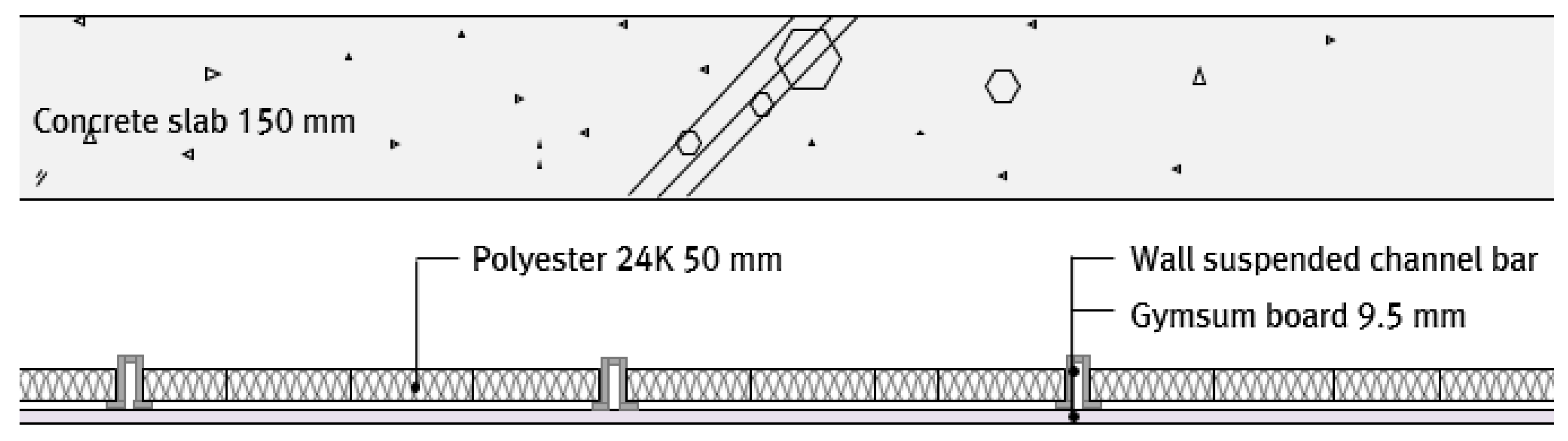
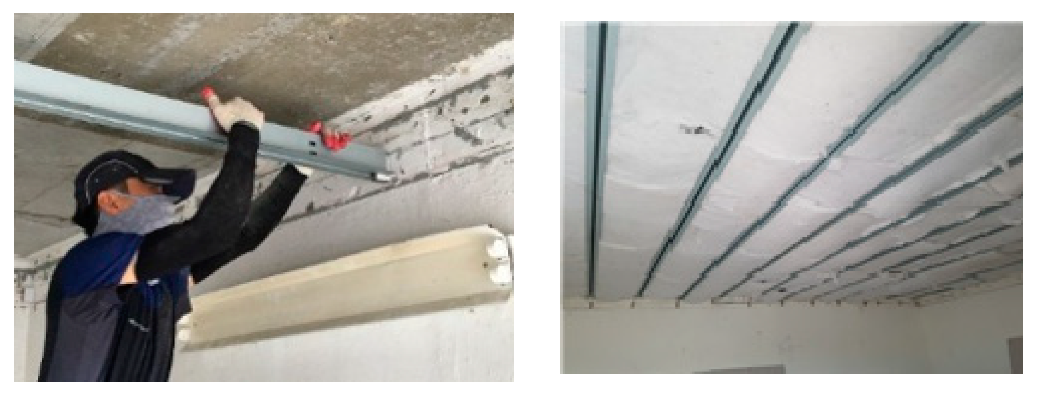
2.1.2. Wall-to-Wall Supported Ceiling (WSC)

The WSC is a ceiling structure developed as a new design concept for the improvement of floor impact sound insulation performance. The WSC was not directly connected to the concrete slab and was considered for faster constructions compared with conventional ceilings. The load of the ceiling structure was directly delivered to the bearing wall using horizontal steel channel bars without hangers. It was intentionally installed in such a way that it was not directly connected with the concrete slab, which can act as a sound bridge. Furthermore, to improve the impact sound insulation and reduce the mass–air–mass resonance effect, a porous material for sound absorption was installed between the steel channel bars inside the air cavity.
Figure 3 shows the cross-sectional diagram of each ceiling structure used in the experiments, and Figure 4 shows the installation of the wall-to-wall supported ceiling structure in the testing facility.

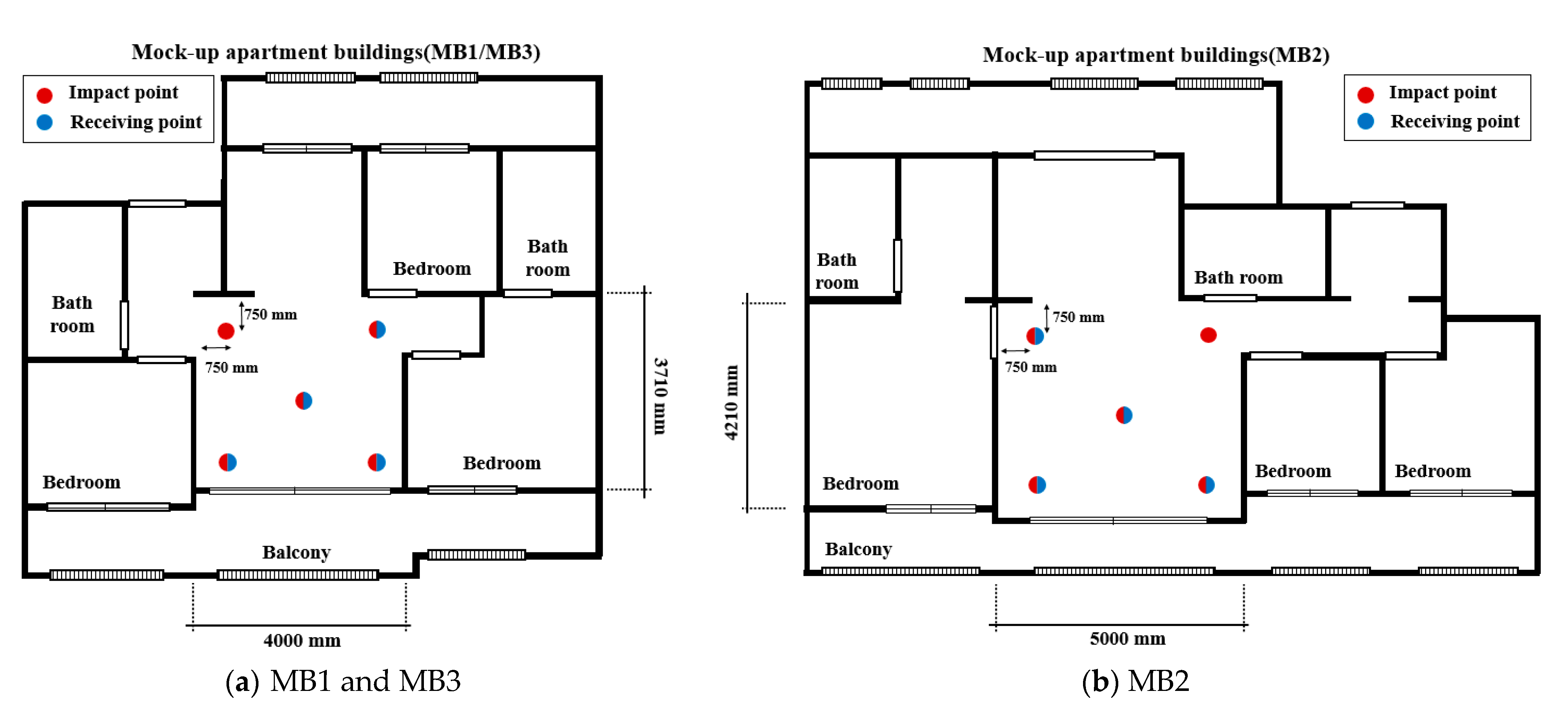
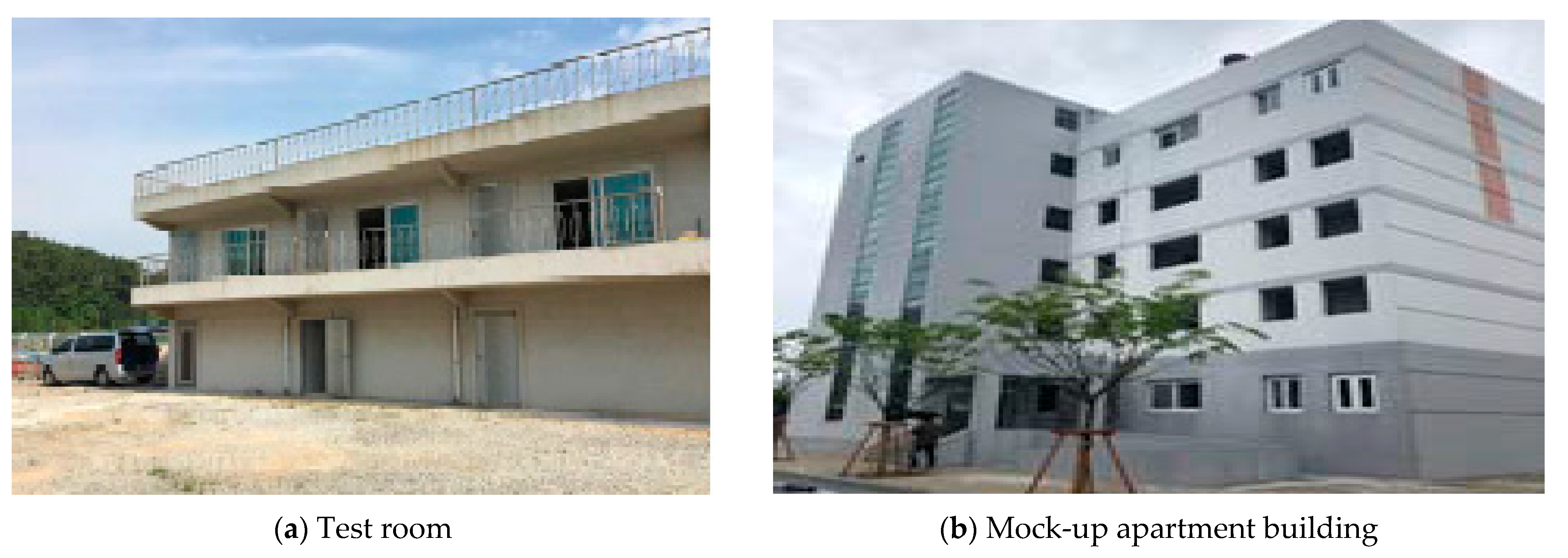
2.2. Test Buildings and Floor–Ceiling Assemblies

To compare the impact sound reduction effects of the conventional ceilings and the wall-to-wall supported ceiling, a total of 25 floor–ceiling assemblies were constructed. Table 1 summarizes an overview of the floor–ceiling assembly and the experimental site. The symbols of floor–ceiling assemblies are listed in alphabetical order. To observe the impact sound level according to the ceiling type and ceiling installation status, the constructions of all floor–ceiling assemblies were determined. The reduction effects of the ACW, that is, the representative ceiling of the existing housing, and the WSC were primarily compared. The sound absorption coefficient of the polyester material used in the air cavity of the WSC is listed in Table 2. The density and thickness of the polyester material were 24 kg/m3 and 50 mm, respectively.
The experiments were performed in test rooms (hereinafter, denoted as “TRn”) and mock-up apartment buildings (hereinafter, denoted as “MBn”) made of the RC wall system. The test room has a rectangular shape with dimensions equal to 4.5 m × 5.1 m × 2.6 m. For the mock-up apartment building, measurements were performed in the living room. Figure 5 and Figure 6 present the floor plans and measurement points for each experimental site, and Figure 7 shows the exterior view of the test room and mock-up apartment building.
The experiments were conducted in four test rooms and three sites of mock-up apartment buildings. The test rooms were named TR1 to TR4 depending on the test room number. Additionally, the experimental sites of mock-up apartment buildings were denoted as MB1 to MB3. The symbols representing the 25 cases of floor–ceiling assemblies were classified by marking the test room number and the representative areas of exclusive use (59 m2 and 84 m2) at the end of a unique alphabet letter, according to the floor plan of the mock-up apartment building. For the test room and mock-up apartment building, the source and receiving rooms were vertically connected with the same floor plan.

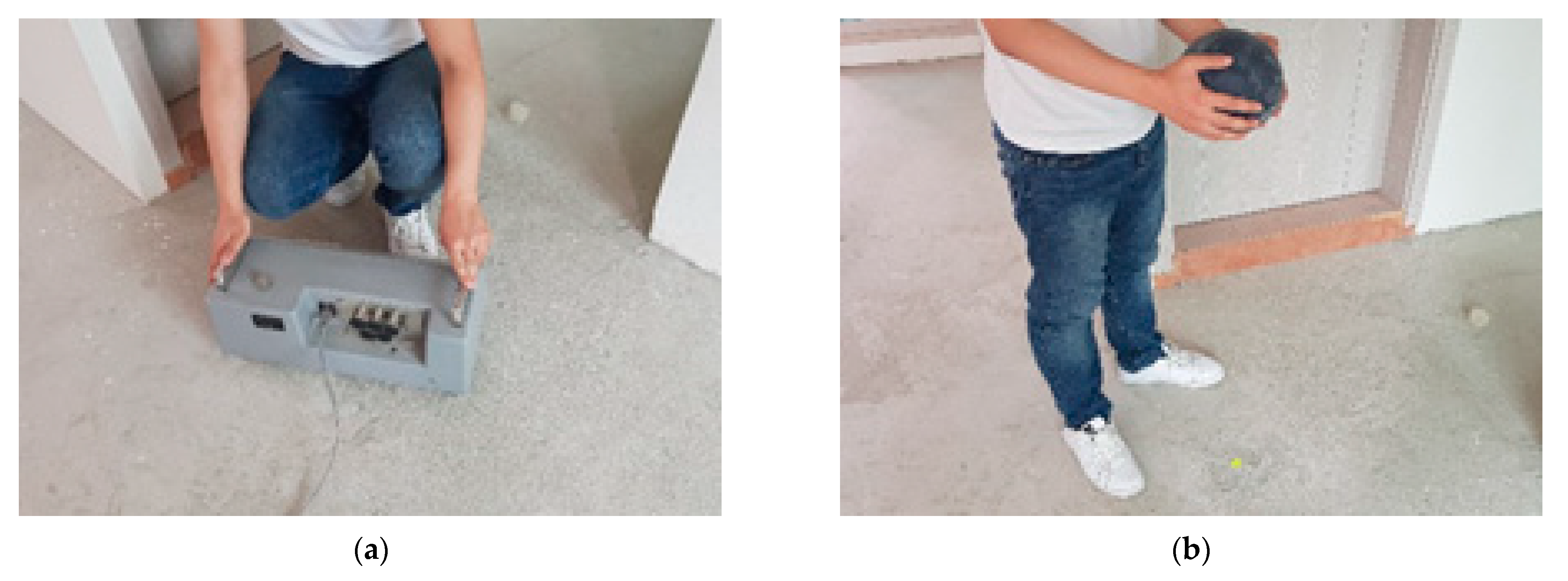
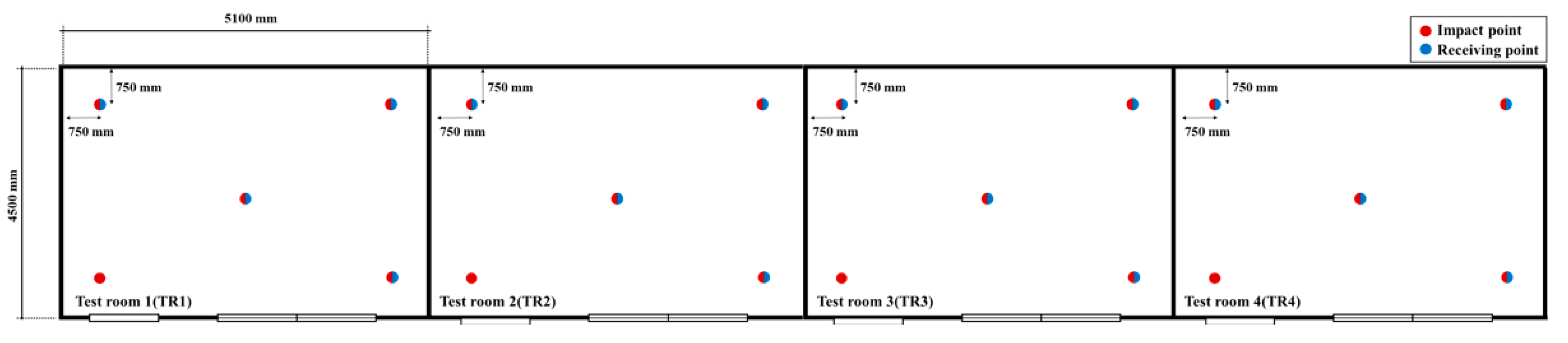
2.3. Measurement Methods

The floor impact sound was measured basically in accordance with ISO 16283-2 [22]. The ISO measurement method is approximately equal to KS F 2810-1 [23] for the tapping machine and KS F 2810-2 [24] for the rubber ball. Particularly, the rubber ball was also standardized in ISO 10140-5 [25] with consideration for heavy and soft impacts such as from walkers on bare feet or children’s running. The rubber ball generates an impulse sound, while the tapping machine generates a quasi-constant sound. Therefore, in the case of the rubber ball, the maximum sound pressure level is considered, and reverberation correction is not applied. According to the standards, two impact sources, the tapping machine as a light impact source and the rubber ball as a heavy impact source, were used. The numbers of impact points and receiving points were five and four, respectively, including the center point. Microphones were located at a height of 1.2 m in the receiving room. The rubber ball was dropped vertically in free fall from the height of 100 ± 1 cm. The equipment for the measurements is listed in Table 3. Figure 8 shows the tapping machine and the rubber ball used in this work.
The measured impact sound pressure levels were evaluated by KS F 2863-1 Annex A [26] for the tapping machine and KS F 2863-2 [27] for the rubber ball, as a rating method. These rating methods were selected to reflect the requirements for the accreditation of the impact sound insulation in Korean apartments. Both impact sources are the same in the reference curve for rating. However, the frequency ranges applied for ratings are partially different.
The reference curve by KS F 2863-1 Annex A and KS F 2863-2 is shown in Figure 9. The SNQ was acquired using the reference curve. The SNQ ( L n , A w ) for the tapping machine was calculated by shifting the reference curve in 1 dB steps until the sum of the octave band values in the range from 125 Hz to 2 k Hz reached a maximum but did not exceed 10 dB. Moreover, the SNQ ( L i , F m a x , A w ) for the rubber ball was calculated by shifting the reference curve in 1 dB steps until the sum in excess of the octave band values in the range from 63 Hz to 500 Hz reached a maximum but did not exceed 8 dB.

3. Results and Discussions

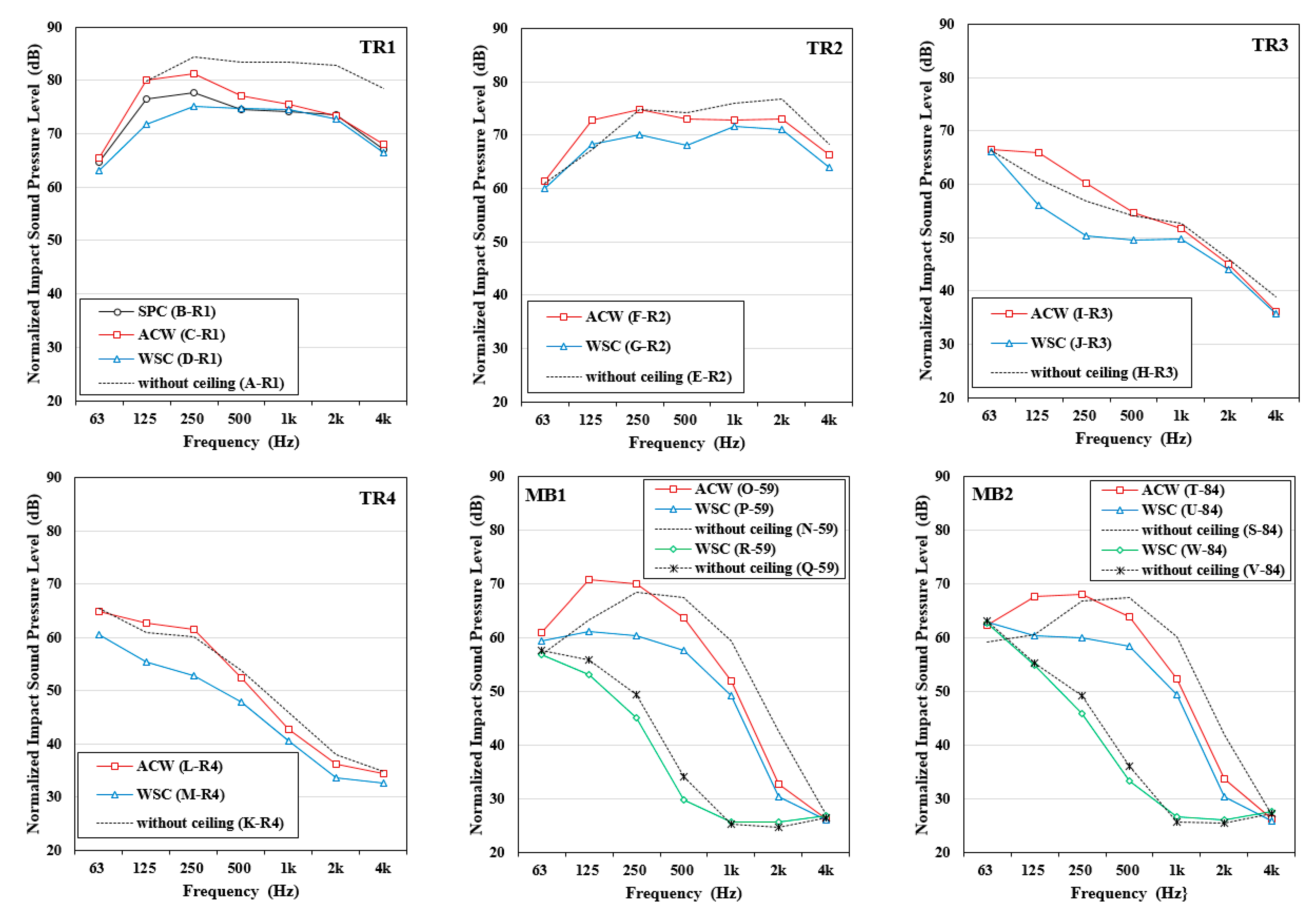
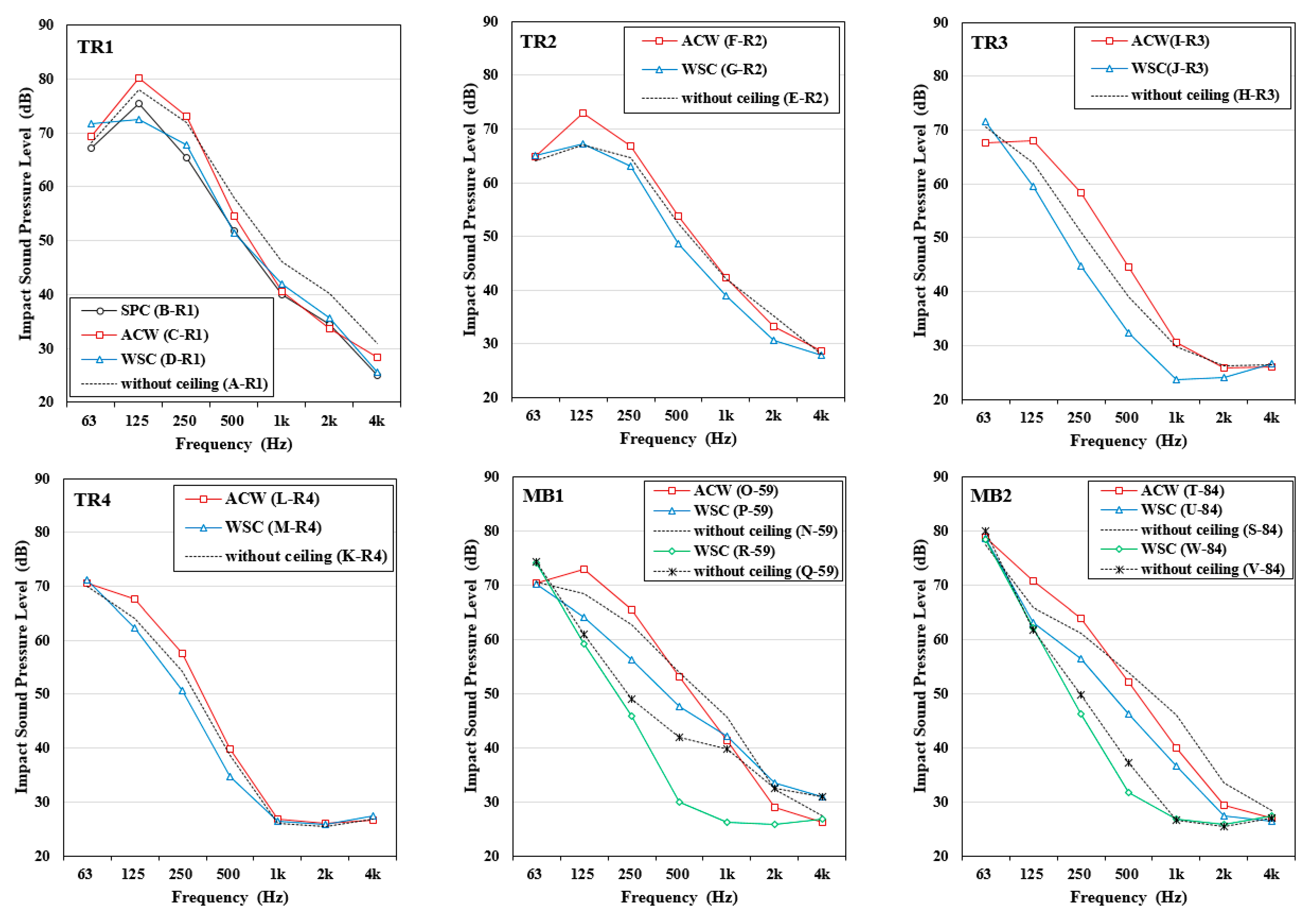
3.1. Impact Sound Pressure Levels

Figure 10 and Figure 11 present the measured results of the floor impact sound level. In each experimental site, the floor impact sound levels were acquired at the same conditions except for the ceiling conditions.
Figure 10 shows the measured results in terms of the normalized impact sound pressure level by a standard light impact source, namely, the tapping machine. The highest floor impact sound level was captured in Test Room 1 (TR1), which was composed of only a bare concrete slab. Test Room 2 (TR2) without the resilient material showed the second-highest impact sound level. TR3 and TR4 were constructed with floating floors by using resilient materials; hence, the floor impact sound level appeared to be lower at a higher frequency band. Furthermore, in MB1, with an exclusive use area of 59 m2, the floor impact sound level of the floor group (N-59, O-59, and P-59) with no resilient material and with PVC flooring yielded typical impact sound reduction characteristics of typical PVC flooring, with a reduced impact sound level in the middle-to-high frequency band [28]. Meanwhile, the floor impact sound level of the floor group (Q-59 and R-59) which used both the resilient material and PVC flooring was clearly lower than that of the floor group (N-59, O-59, and P-59) with only PVC flooring. In particular, from 250 Hz to 1 kHz, the floor impact sound level was significantly reduced, thus indicating that the floating floor system using the resilient material is effective in reducing the impact sound level [29]. The results obtained in MB2 with an exclusive use area of 84 m2 were similar to the measured results obtained in MB1, as mentioned above. Furthermore, it was identified that the difference in the floor impact sound level for each frequency band appeared diversely depending on the ceiling conditions in TR1–4, MB1, and MB2. These results indicate that the reduction in the impact sound level can be achieved by the ceiling structure.
Figure 11 shows the measured results in terms of the impact sound pressure level by the standard heavy impact source, namely a rubber ball, according to KS F 2810-2 Annex B and ISO 16283-2. The results in six experimental sites indicate the typical frequency characteristics of the rubber ball; that is, the floor impact sound level was maximized in the octave bands of 63 Hz or 125 Hz, and it became lower at higher frequencies.
In MB1, compared with the floor group with no resilient material (N-59, O-59, and P-59), the floor impact sound level of the floor group with a resilient material (Q-59 and R-59) decreased more rapidly at a higher frequency band. Similarly, in MB2, the floor impact sound level of the floor group with the resilient material (V-59 and W-59) decreased more rapidly at a higher frequency band than that of the floor group with no resilient material (S-59, T-59, and U-59). This suggests that the floating floor is somewhat effective in reducing the heavyweight impact sound in the middle-to-high frequency band [29]. Furthermore, similar to the measured results of the tapping machine, the impact sound level for each frequency band varied depending on the ceiling conditions in TR 1–4, MB1, and MB2. Based on these results, it is expected that installation of the ceiling structure in addition to the floating floor system will improve the impact sound insulation of heavyweight impact sound.

3.2. Effects of the Wall-to-Wall Supported Ceiling on Impact Sound Reduction

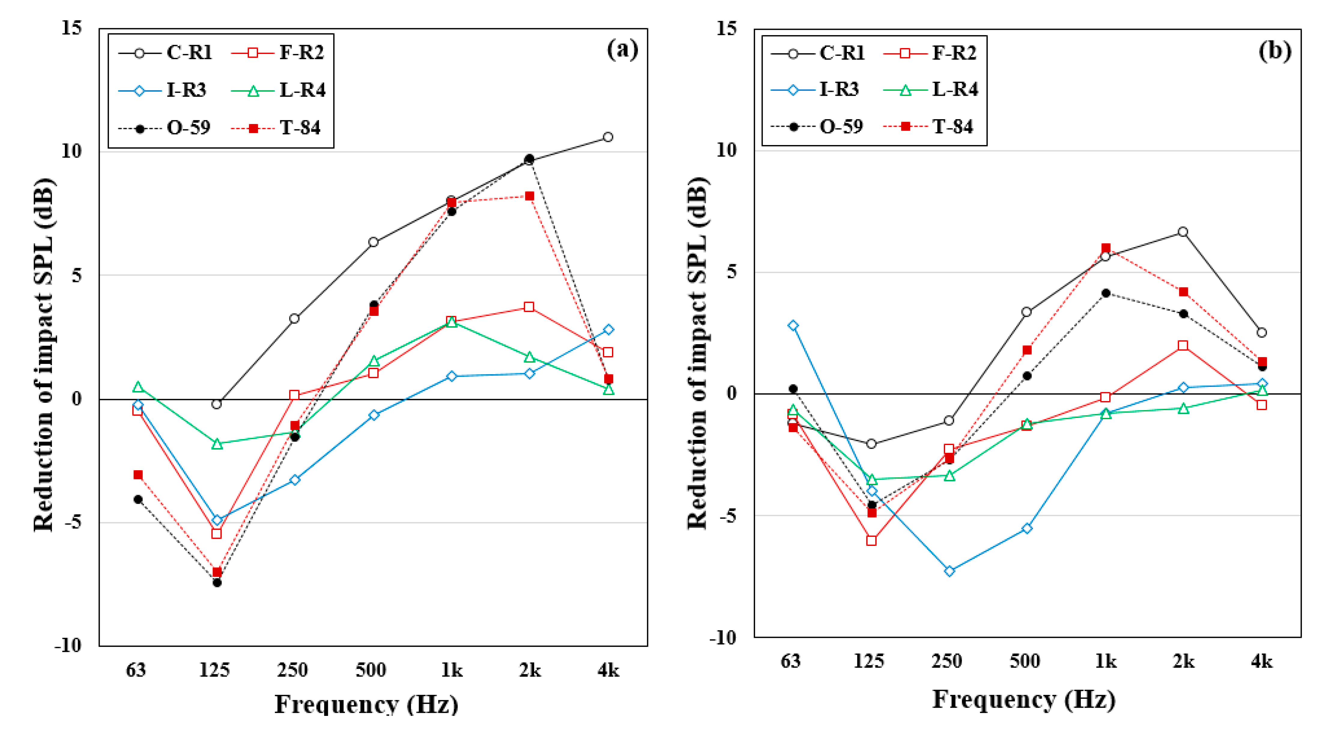
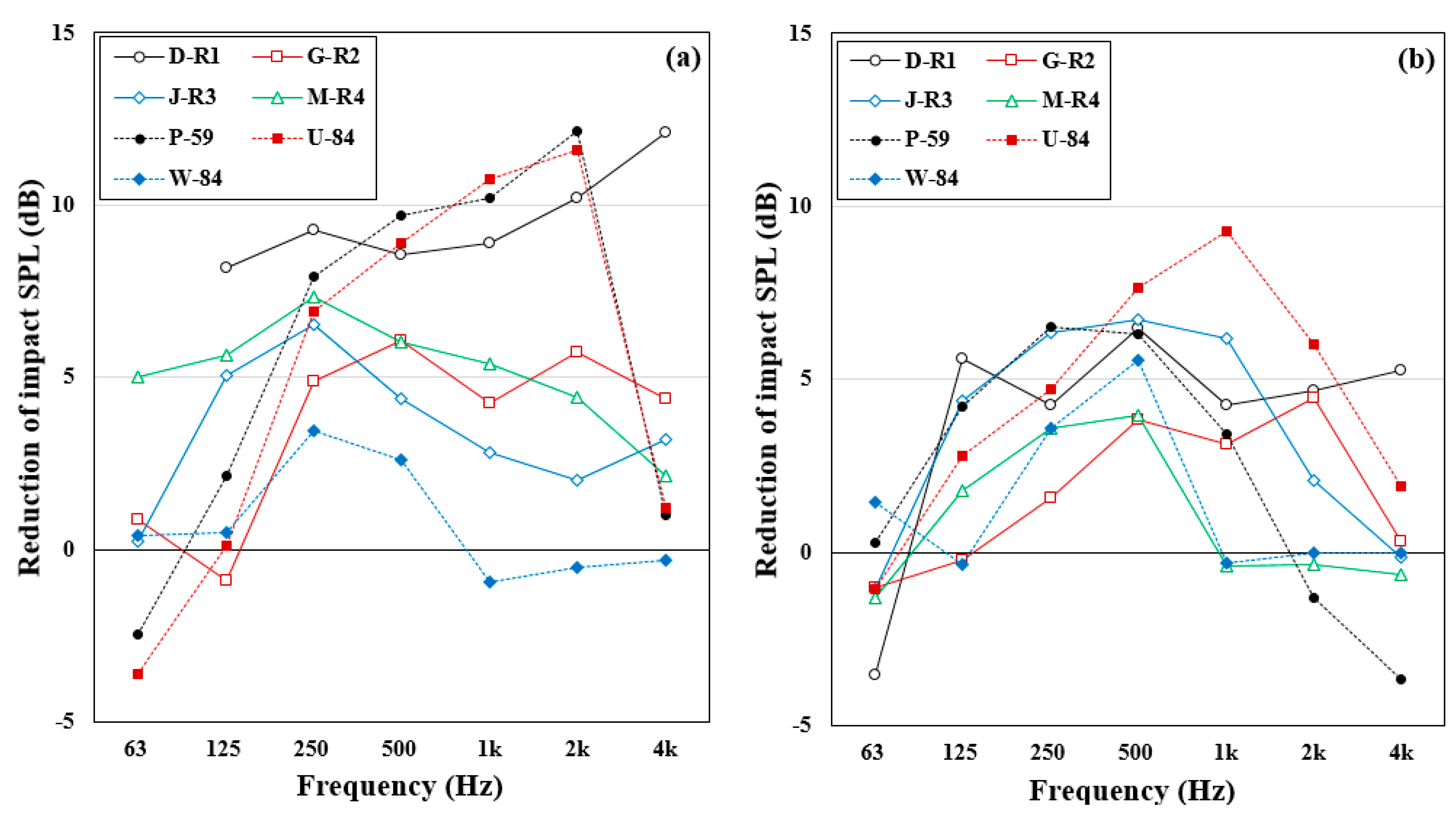
3.2.1. Reductions in Impact Sound Pressure Level

Figure 12 shows the reduction in the impact sound level for each octave band attributed to the installation of the ASW. As shown in Figure 12, a difference in the impact sound level before and after the installation of the ASW was observed up to approximately 10 dB in the middle- and high-frequency ranges (above 500 Hz). In contrast, in the low-frequency range of 63–250 Hz, the impact sound level was amplified after the installation of the ACW, and this amplification was the most pronounced in the frequency band of 125 Hz. Caniato et al. [30] also showed that the impact sound level increased around a frequency of 100 Hz by the screwed ceiling with an air cap of 50 mm.
The reason for this amplification is assumed to be a mass–air–mass resonance owing to the air trapped between the plasterboard and concrete slab which acted as a spring. The resonance frequency of the mass–air–mass system can be estimated as follows [30,31]:
f m a m = 600 m 1 + m 2 d · m 1 · m 2 2
where m 1 and m 2 are the surface densities of the two surfaces in kg/m2, and d is the separation distance between the sides in cm.
Considering the surface densities of 360 kg/m2 and 5.5 kg/m2 for the concrete slab and the plasterboard used as the finishing material of the ceiling, respectively, and the air cavity depth of the two materials (30 mm), the resonance frequency calculated using Equation (1) was set to 150 Hz. This corresponds to an octave band frequency of 125 Hz.
As shown in Figure 12, the amplification of the impact sound pressure level by the mass–air–mass resonance that appeared at approximately 125 Hz is commonly observed for both impact sources, that is, the tapping machine and the rubber ball. Moreover, the impact sound reduction effect at frequencies >500 Hz was more significant in the case of the tapping machine than for the rubber ball. However, footstep noise that is known as the highest complaint noise source in an apartment is significant at low-frequency ranges. Therefore, the typical ACW of the existing housing may induce harmful effects on impact sound insulation for the footstep noise. Therefore, to improve the impact sound insulation of an apartment with an ACW ceiling, ceiling supplementation should be considered.
Figure 13 shows the reduction in impact sound level for each octave band owing to the installation of the WSC. Unlike the suspended ceiling, in the WSC case, the dead load of the ceiling system is generated by the wall. Because there is no hanger that suspends the dead load of the ceiling system, a discontinuity between the ceiling structure and concrete slab is formed, and a porous sound absorber is installed inside the air cavity to reduce the impact sound. Based on the calculation results obtained using Equation (1), the resonance frequency occurred at approximately 58 Hz for an air cavity depth of 200 mm. However, because of the installation of the 50 mm thick polyester sound-absorbing material inside the cavity, the amplification by the mass–air–mass resonance marginally occurred at 63 Hz and 125 Hz. Compared with the ACW presented in Figure 12, it can be observed that the reduction in the impact sound level was significantly improved not only for the tapping machine but also for the rubber ball. Ultimately, the reduction in impact sound level shows an obvious difference depending on the design of the ceiling, and the ceiling structure should be actively utilized as a method to enhance the impact sound insulation.

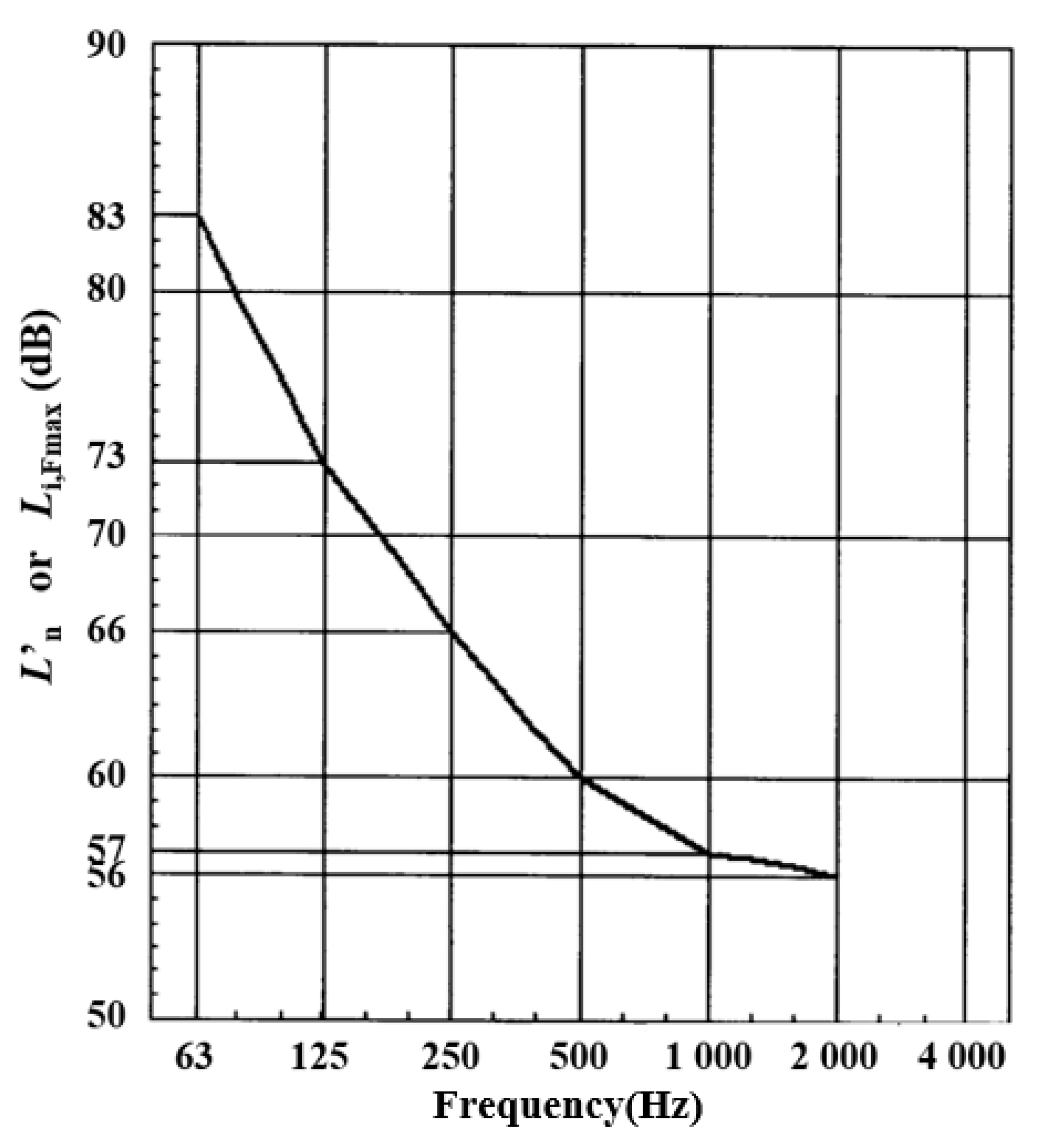
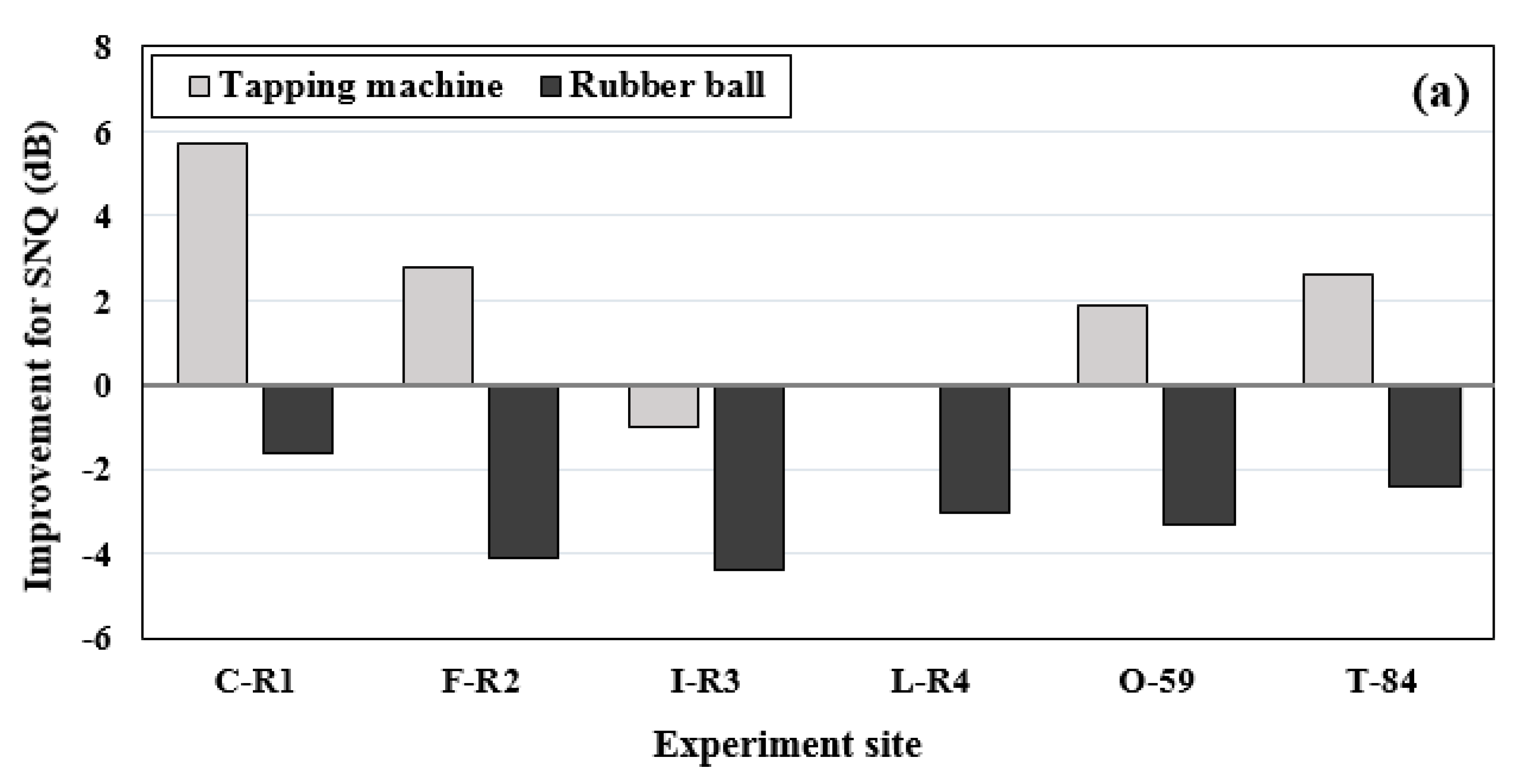
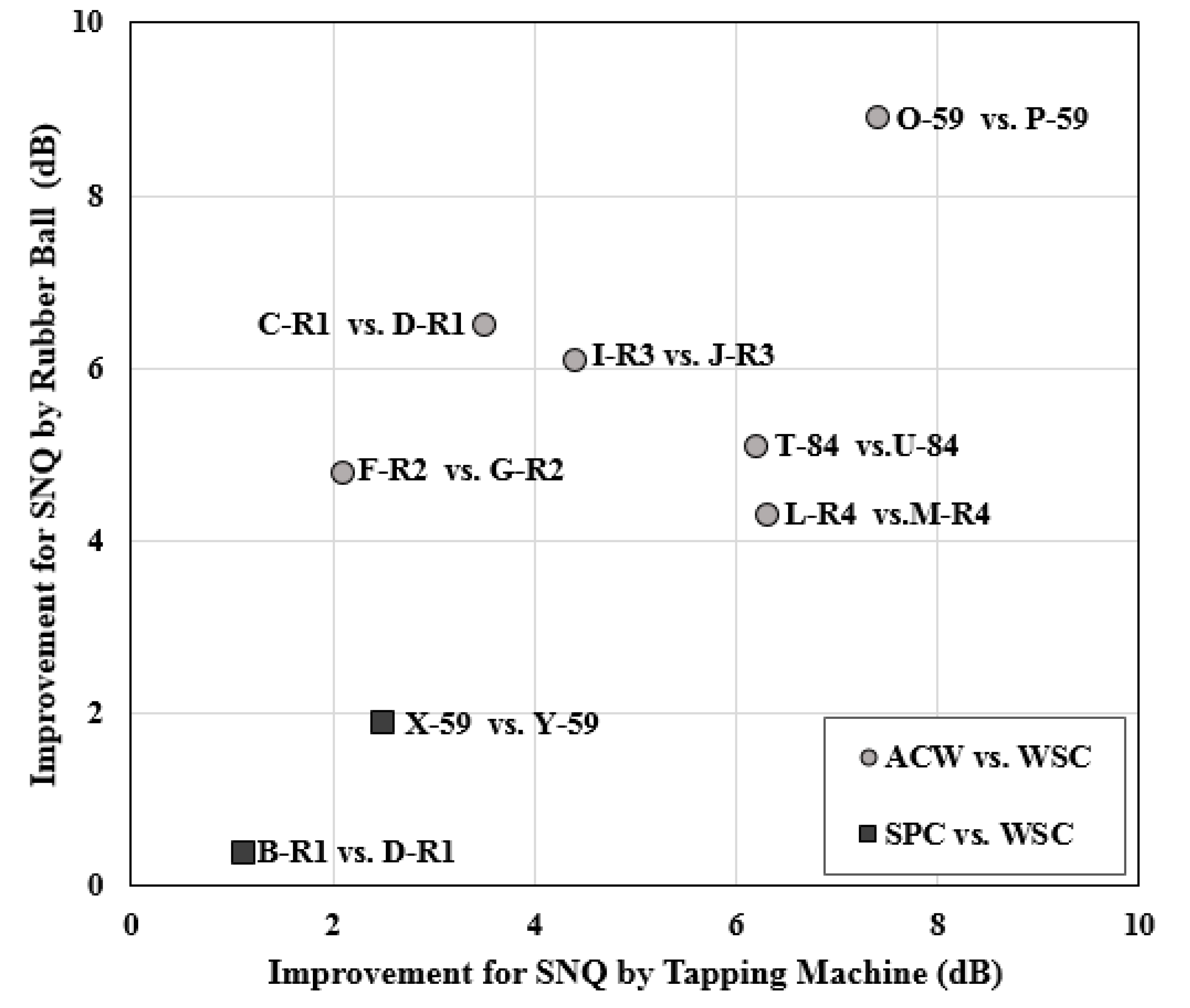
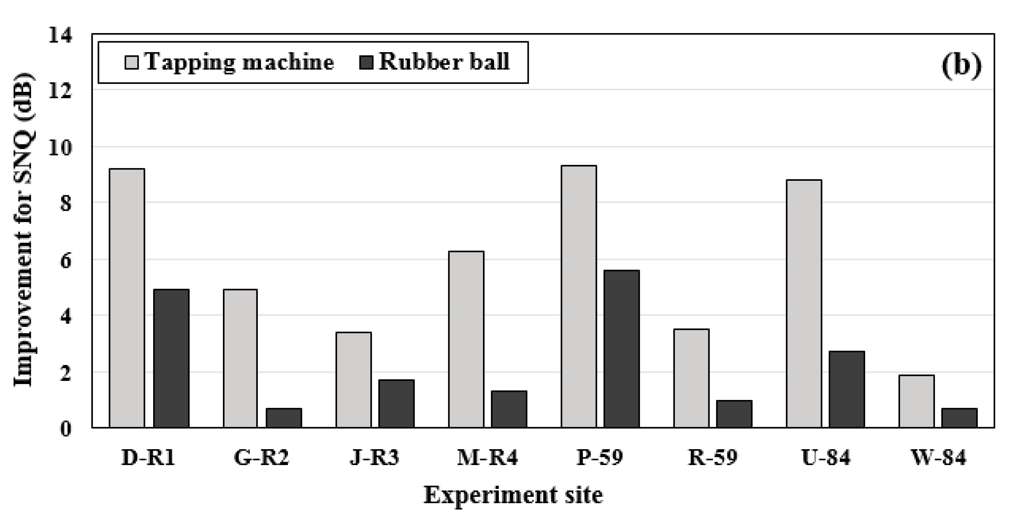
3.2.2. Improvement of the Impact Sound Insulation

Table 4 summarizes the SNQs of 25 floor–ceiling assemblies to represent the floor impact sound insulation performance. The SNQs are L n , A w for the tapping machine and L i , F m a x , A w for the rubber ball according to KS F 2863. Different ceiling conditions were used for each of the seven sites at which the tests were performed, but the concrete slab and floor layers were the same.
The cases tested in TR1, which is composed of a bare concrete slab only, and TR2, which is composed of a non-floating floor with no resilient material, exhibited higher SNQs compared with those of the cases tested in TR3 and TR4 with floating floor structures and resilient materials. Therefore, for both impact sources (namely, the tapping machine and rubber ball), the presence of the floating floor structure was found to have a significant effect on the impact sound insulation performance. Furthermore, the presence of PVC flooring and the wall-to-wall supported ceiling was also found to affect the SNQ. The SNQs of the test cases (M-R4, R-59, and W-84), where the resilient material, PVC floorings, and wall-to-wall supported ceiling were used, were 35–43 dB for the tapping machine and 45–49 dB for the rubber ball. These outcomes are indicative of great impact sound insulation performances.
Figure 14 shows the improvement in impact sound insulation in terms of SNQ based on the installation of the ACW and the WSC in comparison with the SNQ (no ceiling condition). This means that the larger the improvement for SNQ, the better the impact sound reduction induced by the ceiling installation. According to KS F 2863-1, 2 [22,23], the SNQ should be indicated as a whole number with a unit of 1 dB. However, for a more detailed analysis, in this study, SNQ was calculated and quantitatively compared at an accuracy of one decimal place.
Figure 14a shows the improvement of SNQ caused by the ACW, that is, the representative ceiling structure of the existing housing in six test sites. The improvement in SNQ ranged from −1.0 dB to 5.7 dB for the tapping machine, and from −1.6 dB to −4.4 dB for the rubber ball following the installation of the ACW. The impact sound insulation for the tapping machine was improved in four out of the six test sites. However, for the rubber ball, the impact sound insulation was found to deteriorate following the installation of the ACW at all six test sites. This can explain the fact that the typical impact sounds generated owing to the rubber ball’s impact were maximized at approximately 63 Hz and 125 Hz, while the impact sound insulation of the ACW deteriorated at frequencies within the 125 Hz band owing to its mass–air–mass resonance. Therefore, to enhance the floor impact sound insulation of the existing housings with the ACW, it is necessary to consider the improvement of the ceiling structure.
Figure 14b presents the SNQ improvement following the installation of the WSC devised to improve the impact sound insulation. It was found that in comparison with the SNQ in the no-ceiling condition, the improvement of SNQ ranged from 1.9 dB to 5.7 dB in the case of the tapping machine and from 0.7 dB to 5.6 dB in the case of the rubber ball. Even though the same WSC was installed below the concrete slab of the experimental sites, the improvement in SNQ varied in accordance with floor structure conditions above the concrete slab. The improvement in SNQ for non-floating floor structures made without resilient materials was more pronounced than that for floating floor structures made with resilient materials. In other words, the effect of the WSC on impact sound insulation was more noticeable for floor structures with poor impact sound insulation. For example, it was found that the SNQ improvement by the same WSC was less in R-59 (tapping M.: 3.5 dB, R. ball: 1.0 dB) in the floating floor case compared with P-59 (tapping M.: 9.3 dB, R. ball: 5.6 dB) for the non-floating floor case. Additionally, it can be observed that the SNQ improvement was less in W-84 (tapping M.: 2.7 dB, R. ball: 0.7 dB) for the floating floor case than in U-84 (tapping M.: 8.8 dB, R. ball: 2.7 dB) for the non-floating floor case.
The reason is estimated such that the resilient material played a leading role in the impact sound insulation of the floor-ceiling assembly. Hence, the improvement effect of the WSC was relatively decreased in floating floor structures with resilient materials. Therefore, this means the WSC can be used more effectively in a floor structure with poor sound insulation, such as a floor structures with no resilient material or no soft floorings, or thin concrete slabs, etc. Furthermore, in the case of renovation for impact sound reduction, because the WSC can be easily installed for repairing the existing ceiling without disassembling the floor structures, it can be utilized as a useful reduction method in impact sound in terms of cost and construction time.
Figure 15 shows the SNQ representing the reduction effect of the WSC devised for impact sound reduction, compared with that of ACW and SPC which are conventional ceilings. In other words, this signifies the improvement in the impact sound insulation to be expected when replacing an ACW or SPC with a WSC.
The SNQ difference between the ACW and the WSC ranged from 2.1 to 7.4 dB for the tapping machine and from 4.3 to 8.9 dB for the rubber ball in six experimental sites. The ACW performs poorly on impact sound insulation because of the effect of the mass–air–mass resonance and the large sound bridge area by the square wood stick between the concrete slab and the ceiling plate. Therefore, if the ACW is replaced with the WSC, the impact sound insulation performance is expected to be improved considerably for both the tapping machine and rubber ball. In addition, the SNQ difference between the SPC and WSC ranged from 1.1 to 2.5 dB for the tapping machine and from 0.4 to 1.9 dB for the rubber ball in the two experimental sites. This difference is attributed to the discontinuity composition between the ceiling structure and slab, and the installation of the porous sound absorber inside the cavity. Even though the SNQ difference between the SPC and WSC is not so large, it is important. Because SPCs have been used in newer apartments, various impact sound reduction techniques were already considered. Thus, it is expected that the performance will be improved owing to the difference in the ceiling structure. Additionally, replacing the ceiling structure will be used as one of the helpful reduction tools.

4. Conclusions

In this study, we investigated the effects of ceilings on impact sound reduction. The wall-to-wall supported ceiling and conventional ceilings used in apartments in South Korea were selected. The WSC is a ceiling structure developed as a new design concept for the reduction in floor impact sound. Measurements were performed in 25 floor–ceiling assemblies in test rooms and mock-up apartment buildings.
Based on the analysis results of various test cases, the improvement in impact sound insulation in terms of SNQ varied in accordance with floor structure conditions above the concrete slab in cases in which the ceilings were the same. Furthermore, the reduction degree in impact sound level by the installed ceiling was generally more pronounced for the tapping machine light impact source than for the rubber ball.
In the case of the ACW which was mainly employed for the ceiling of existing apartments, the impact sound insulation was found to deteriorate after the installation of the ACW owing to its mass–air–mass resonance. To enhance the floor impact sound insulation of the existing housings with the ACW, it is necessary to consider the improvement of ceiling structures.
In the case of the WSC, it was found that, in comparison with the SNQ in cases in which there were no ceilings, the improvement of SNQ ranged from 1.9 dB to 5.7 dB in the case of the tapping machine, and from 0.7 dB to 5.6 dB in the case of the rubber ball. Specifically, the effect of the WSC on impact sound insulation was more noticeable for floor structures with poor impact sound insulation, such as non-floating floor structures, constructed without resilient materials. This reduction by the WSC was attributed to the discontinuity composition between the ceiling structure and concrete slab, and to the installation of the porous sound absorber inside the cavity.
The SNQ differences between the ACW and the WSC ranged from 2.1 to 7.4 dB for the tapping machine, and from 4.3 to 8.9 dB for the rubber ball in six experimental sites. Additionally, the SNQ differences between the SPC and WSC were in the range of 1.1–2.5 dB for the tapping machine, and in the range of 0.4–1.9 dB for the rubber ball in two experiment sites. Therefore, if the conventional ceilings are replaced with the WSC, the impact sound insulation is expected to be significantly improved for both the tapping machine and rubber ball. In the case of renovation for impact sound reduction, because the WSC can be easily installed for repairing the existing ceiling without disassembling the floor structures, it can be effectively used as a useful reduction method in impact sound in terms of cost and construction time.
In this study, it was determined that not only floor structures but also ceiling treatments were useful for reducing the floor impact sound level. However, even for the same ceiling system, the reduction effect can change depending on the floor structure, floor assemblies, floor plane type, and receiving-room conditions; hence, additional in-depth studies are required to prepare the optimized ceiling design based on considerations of the impact sound insulation performance.

Author Contributions

Conceptualization, S.-T.K. and H.-M.C.; validation, S.-T.K. and H.-M.C.; formal analysis, H.-M.C. and M.-J.K.; investigation, S.-T.K. and H.-M.C.; data curation, S.-T.K. and M.-J.K.; writing—original draft preparation, S.-T.K. and H.-M.C.; writing—review and editing, M.-J.K.; visualization, S.-T.K.; supervision, M.-J.K.; project administration, S.-T.K.; funding acquisition, M.-J.K. All authors have read and agreed to the published version of the manuscript.

Funding

This research was supported by the Korean Agency for Infrastructure Technology Advancement (KAIA) grant funded by the Ministry of Land, Infrastructure, and Transport (Grant 21CTAP-C152256-03).

Institutional Review Board Statement

Not applicable.

Informed Consent Statement

Not applicable.

Data Availability Statement

The datasets used and analyzed during in the study are available in original languages from the corresponding author on reasonable request.

Conflicts of Interest

The authors declare no conflict of interest.

References

  1. Jeon, J.Y.; Ryu, J.K.; Lee, P.J. A Quantification Model of Overall Dissatisfaction with Indoor Noise Environment in Residential Buildings. Appl. Acoust. 2010, 71, 914–921. [Google Scholar] [CrossRef]
  2. Ljunggren, F.; Simmons, C.; Hagberg, K. Correlation between Sound Insulation and Occupants’ Perception—Proposal of Alternative Single Number Rating of Impact Sound. Appl. Acoust. 2014, 85, 57–68. [Google Scholar] [CrossRef]
  3. Yang, H.; Kim, T. Parametric Study on Floor Impact Sound with Design Factors of Layers Composing a Floating Floor in Multi-Residential Buildings. Trans. Korean Soc. Noise Vib. Eng. 2020, 30, 119–128. [Google Scholar] [CrossRef]
  4. Kim, T.; Bae, J.; Yang, H. The Study on Characteristic of Floor Impact Noise Using the Structural Vibration on Floor Slab: Effective Plate. Trans. Korean Soc. Noise Vib. Eng. 2020, 30, 276–285. [Google Scholar] [CrossRef]
  5. Song, G.; Kim, Y.; Ryu, J.; Kim, M. Analysis of Heavyweight Floor Impact Sound Level with Dynamic Stiffness and Thickness of EPS Type Resilient Materials. Trans. Korean Soc. Noise Vib. Eng. 2018, 28, 713–720. [Google Scholar] [CrossRef] [Green Version]
  6. Park, H.; Oh, B.; Kim, Y.; Cho, T. Low-frequency impact sound transmission of floating floor: Case study of mortar bed on concrete slab with continuous interlayer. Build. Environ. 2015, 94, 793–801. [Google Scholar] [CrossRef]
  7. Kim, K.; Jeong, G.; Yang, K.; Sohn, J. Correlation between Dynamic Stiffness of Resilient Materials and Heavyweight Impact Sound Reduction Level. Build. Environ. 2009, 44, 1589–1600. [Google Scholar] [CrossRef]
  8. Schiavi, A. Improvement of Impact Sound Insulation: A Constitutive Model for Floating Floors. Appl. Acoust. 2018, 129, 64–71. [Google Scholar] [CrossRef]
  9. Schiavi, A.; Belli, A.P.; Corallo, M.; Russo, F. Acoustical Performance Characterization of Resilient Materials Used Floating Floor in Dwellings. Acta Acust. Acoust. 2007, 93, 477–485. [Google Scholar]
  10. Caniato, M.; Bettarello, F.; Marsich, L.; Feruga, A.; Sbaizero, O.; Schmid, C. Time-depending performance of resilient layers under floating floors. Constr. Build. Mater. 2016, 102, 226–232. [Google Scholar] [CrossRef]
  11. Caniato, M.; Schmid, C.; Gasparella, A. A comprehensive analysis of time influence on floating floors: Effects on acoustic performance and occupants’ comfort. Appl. Acoust. 2020, 166, 107339. [Google Scholar] [CrossRef]
  12. Hopkins, C. Sound Insulation; Elsevier Ltd.: Burlington, NJ, USA, 2007. [Google Scholar]
  13. Hassan, O.A.B. Building Acoustics and Vibration: Theory and Practice; World Scientific Publishing Co.: Singapore, 2009. [Google Scholar]
  14. Kim, K.; Kang, J.; Lee, S.; Yang, K. Floor Impact Sound Isolation Performance by Composition of Ceiling and Wall. Trans. Korean Soc. Noise Vib. Eng. 2005, 15, 465–473. [Google Scholar]
  15. Ryu, J.; Song, H.; Kim, Y. Effect of the Suspended Ceiling With Low-Frequency Resonant Panel Absorber on Heavyweight Floor Impact Sound in the Building. Build. Environ. 2018, 139, 1–7. [Google Scholar] [CrossRef]
  16. Shin, H.; Kim, K. Analysis Effects of Perforated Gypsum Board Ceiling Structure for Floor Impact Sound Reduction. Trans. Korean Soc. Noise Vib. Eng. 2009, 29, 511–517. [Google Scholar] [CrossRef]
  17. Bettarello, F.; Gasparella, A.; Caniato, M. The influence of layering on airborne sound insulation and impact noise reduction: A study on Cross Laminated Timber (CLT) structures. Appl. Sci. 2021, 11, 5938. [Google Scholar] [CrossRef]
  18. Souza, C.F.N.; Pacheco, F.; Oliveira, M.F.; Heissler, R.F.; Tutikian, B.F. Impact Sound Insulation of Floor Systems with Hollow Brick Slabs. Case Stud. Constr. Mater. 2020, 13, e00387. [Google Scholar] [CrossRef]
  19. Sipari, P. Sound Insulation of Multi-Storey Houses, a Summary of Finnish Impact Sound Insulation Results. Build. Acoust. 2000, 7, 15–30. [Google Scholar] [CrossRef]
  20. Huang, E. Field Floor Impact Noise South-East Queensland (Australia). In Proceedings of the 43rd International Congress on Noise Control Engineering (Inter-Noise 2014), Melbourne, Australia, 16–19 November 2014. [Google Scholar]
  21. Hui, C.K.; Ng, C.F. Improvement of Lightweight Floating Ceiling Design with Optimum Stiffener and Isolator Locations. J. Sound Vib. 2009, 327, 333–353. [Google Scholar] [CrossRef]
  22. International Organization for Standardization. ISO 16283-2. Acoustics—Field Measurement of Sound Insulation in Buildings and Building Elements—Part 2: Impact Sound Insulation; ISO: Geneva, Switzerland, 2020. [Google Scholar]
  23. Korean Agency for Technology and Standards. KS F 2810-1. Field Measurement of Impact Sound Insulation of Floors, Part 1: Method Using Standard Light Impact Source; Korean Agency for Technology and Standards: Seoul, Korea, 2001.
  24. Korean Agency for Technology and Standards. KS F 2810-2. Field Measurement of Impact Sound Insulation of Floors, Part 2: Method Using Standard Heavy Impact Sources; Korean Agency for Technology and Standards: Seoul, Korea, 2012.
  25. International Organization for Standardization. ISO 10140-5. Acoustics—Laboratory Measurement of Sound Insulation of Building Elements—Part 5: Requirement for Test Facilities and Equipment; ISO: Geneva, Switzerland, 2010. [Google Scholar]
  26. Korean Agency for Technology and Standards. KS F 2863-1. Rating of Floor Impact Sound Insulation for Impact Source in Buildings and of Building Elements, Part 1: Floor Impact Sound Insulation against Standard Light Impact Source; Korean Agency for Technology and Standards: Seoul, Korea, 2017.
  27. Korean Agency for Technology and Standards. KS F 2863-2. Rating of Floor Impact Sound Insulation for Impact Source in Buildings and of Building Elements, Part 2: Floor Impact Sound Insulation against Standard Heavy Impact Source; Korean Agency for Technology and Standards: Seoul, Korea, 2017.
  28. Mun, D.; Song, G.; Lee, C.; Park, H. Reduction of Floor Impact Noise and Impact Force for PVC Floor Covering and Floor Mat. Trans. Korean Soc. Noise Vib. Eng. 2014, 24, 501–508. [Google Scholar] [CrossRef]
  29. Kim, S.; Cho, H.; Kim, M. A Study on Improvement of Floor Impact Sound Insulation Performance in Repairing Floor Layers of Aged Apartment. Trans. Korean Soc. Noise Vib. Eng. 2019, 29, 206–215. [Google Scholar] [CrossRef]
  30. Caniato, M.; Bettarello, F.; Fausti, P.; Ferluga, A.; Marsich, L.; Schmid, C. Impact sound of timber floors in sustainable buildings. Build. Environ. 2017, 120, 110–122. [Google Scholar] [CrossRef]
  31. Long, M. Architectural Acoustics; Elsevier Academic Press: London, UK, 2006; pp. 278–279. [Google Scholar]
Figure 1. Cross-sections of conventional ceiling structures: (a) Cross-sectional view of the attached ceiling on a wooden stick, ACW and (b) Cross-sectional view of the suspended ceiling, SPC.
Buildings 11 00587 g001
Figure 2. Installation view of conventional ceilings: (a) ACW and (b) SPC.
Buildings 11 00587 g002
Figure 3. Cross-section of the wall-to-wall supported ceiling structure.
Buildings 11 00587 g003
Figure 4. Installation view of the wall-to-wall supported ceiling.
Buildings 11 00587 g004
Figure 5. Floor plan and measurement points of test rooms.
Buildings 11 00587 g005
Figure 6. Floor plan and measurement points of mock-up apartment buildings: (a) MB1 and MB3 (they differ only in the thickness of the slab in the same plane), mock-up apartment building area: 59 m2, and (b) MB2, mock-up apartment building area: 84 m2.
Buildings 11 00587 g006
Figure 7. Exterior views of the test room and mock-up apartment buildings.
Buildings 11 00587 g007
Figure 8. Standard impact sources: (a) tapping machine and (b) rubber ball.
Buildings 11 00587 g008
Figure 9. The reference curve and octave band reference values by Korean Standards.
Buildings 11 00587 g009
Figure 10. Normalized impact sound pressure levels for the tapping machine in accordance with ceiling conditions for test rooms and mock-up apartment buildings.
Buildings 11 00587 g010
Figure 11. Impact sound pressure levels for the rubber ball in accordance with ceiling conditions for test rooms and mock-up apartment buildings.
Buildings 11 00587 g011
Figure 12. Reduction in impact sound pressure level following the installation of ACW in the experiment sites: (a) tapping machine and (b) rubber ball.
Buildings 11 00587 g012
Figure 13. Reduction in impact sound pressure level following the installation of WSC in the experimental sites: (a) tapping machine and (b) rubber ball.
Buildings 11 00587 g013
Figure 14. Improvement in impact sound insulation (SNQ) following the installation of ceilings compared with SNQ in cases wherein there was no ceiling: (a) ACW and (b) WSC.
Buildings 11 00587 g014aBuildings 11 00587 g014b
Figure 15. Improvement in impact sound insulation (SNQ) for the wall-to-wall supported ceiling (WSC) in comparison with SNQ for conventional ceilings (ACW and SPC).
Buildings 11 00587 g015
Table 1. Details of floor–ceiling assembly for the measurement of impact sound.
SymbolA-R1B-R1C-R1D-R1E-R2F-R2G-R2H-R3I-R3
Experiment SiteTR1TR1TR1TR1TR2TR2TR2TR3TR3
Floor covering (mm)---------
Finish mortar (mm)----4545454040
Aerated concrete (mm)----6565654040
Resilient material (mm)
(Dynamic stiffness, MN/m3)
-------EPS 20
(DS 10)
EPS 20
(DS 10)
Concrete slab (mm)150150150150150150150150150
Air cavity (mm)-15030200-30200-30
Absorber (polyester 24K) (mm)---50-----
Plaster board (mm)-9.59.59.5-9.59.5-9.5
Ceiling type-SPCACWWSC-ACWWSC-ACW
SymbolJ-R3K-R4L-R4M-R4N-59O-59P-59Q-59R-59
Experiment SiteTR3TR4TR4TR4MB1MB1MB1MB1MB1
Floor covering (mm)----22266
Finish mortar (mm)404040404545454040
Aerated concrete (mm)404040406565654040
Resilient material (mm)
(Dynamic stiffness, MN/m3)
EPS 20
(DS 10)
EPS 20
(DS 10)
EPS 20
(DS 10)
EPS 20
(DS 10)
---EPS 20
(DS 10)
EPS 20
(DS 10)
Concrete slab (mm)150150150150150150150150150
Air cavity (mm)200-30200-30200-200
Absorber (polyester 24K) (mm)50--50--50-50
Plaster board (mm)9.5-9.59.5-9.59.5-9.5
Ceiling typeWSC-ACWWSC-ACWWSC-WSC
SymbolS-84T-84U-84V-84W-84X-59Y-59
Experiment SiteMB2MB2MB2MB2MB2MB3MB3
Floor covering (mm)22266--
Finish mortar (mm)45454540404040
Aerated concrete (mm)65656540404040
Resilient material (mm)
(Dynamic stiffness, MN/m3)
---EPS 20
(DS 10)
EPS 20
(DS 10)
EPS 30
(DS 20)
EPS 30
(DS 20)
Concrete slab (mm)150150150150150210210
Air cavity (mm)-30200-200170170
Absorber (polyester 24K) (mm)--50-50-50
Plaster board (mm)-9.59.5-9.59.59.5
Ceiling type-ACWWSC-WSCSPCWSC
TRs: test room (number), MBs: mock-up apartment building (number), EPS: expanded polystyrene, DS: dynamic stiffness, WSC: wall-to-wall supported ceiling, ACW: attached ceiling on wood stick, SPC: suspended ceiling.
Table 2. Sound absorption coefficient of porous material.
125 Hz250 Hz500 Hz1 kHz2 kHz4 kHzNRC *
0.260.600.750.860.830.830.76
* NRC: noise reduction coefficient.
Table 3. Test equipment.
EquipmentModel and Maker
Light impact source Tapping machine (TM01), 01 dB
Heavy impact sourceRubber ball (Y1-01), NOK
Frequency analyzerdB4_4ch, 01 dB and SA-02, RION
MicrophoneMPA 201, BSWA TECH
CalibratorNC-74, RION
Table 4. Single number quantities of floor–ceiling assemblies.
Experiment SiteTest Room 1 (TR1)Test Room 2 (TR2)Test Room 3 (TR3)Test Room 4 (TR4)
SymbolA-R1B-R1C-R1D-R1E-R2F-R2G-R2H-R3I-R3J-R3K-R4L-R4M-R4
L n , A w (dB)83757774757270515247494943
L i , F m a x , A w (dB)62576457535752465044475045
Experiment SiteMock-Up Bld. 1 (MB1)Mock-Up Bld. 2 (MB2)Mock-Up Bld. 3 (MB3)
SymbolN-59O-59P-59Q-59R-59S-84T-84U-84V-84W-84X-59Y-59
L n , A w (dB)615952393561585238363836
L i , F m a x , A w (dB)535648464553555049494442
Publisher’s Note: MDPI stays neutral with regard to jurisdictional claims in published maps and institutional affiliations.

