Modeling of an Aerogel-Based “Thermal Break” for Super-Insulated Window Frames

 ,
,  ,
,  ,
, 


Abstract
1. Introduction
1.1. Aerogel for Super-Insulation
1.2. Aerogel Products for Constructions
1.3. Aerogel Insulation for Windows
2. Materials and Methods
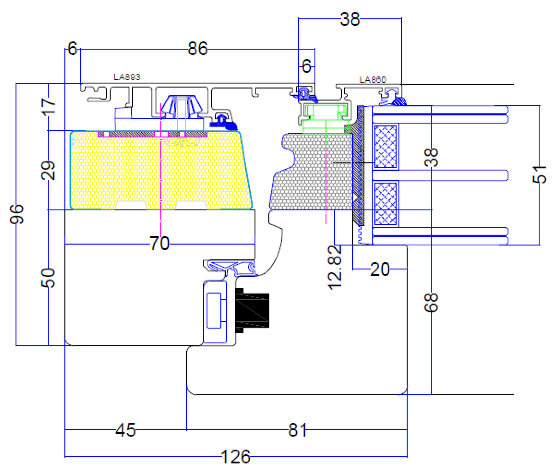
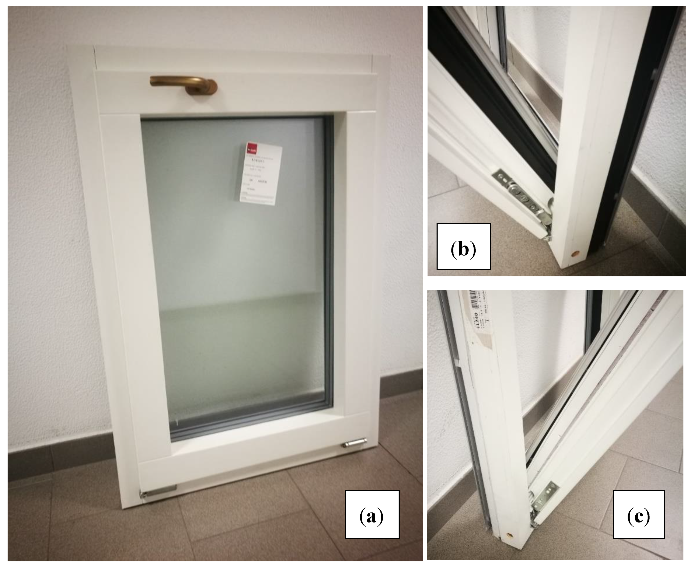
2.1. Frame and Window Description
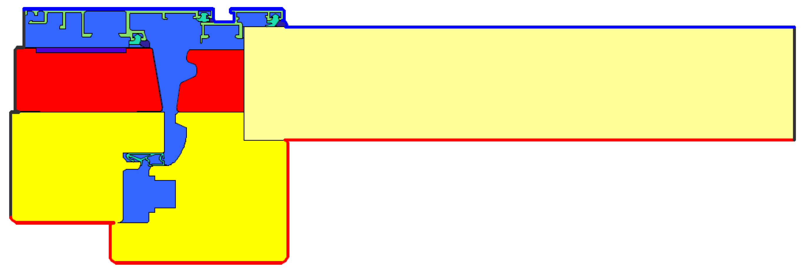
2.2. Finite Element Method
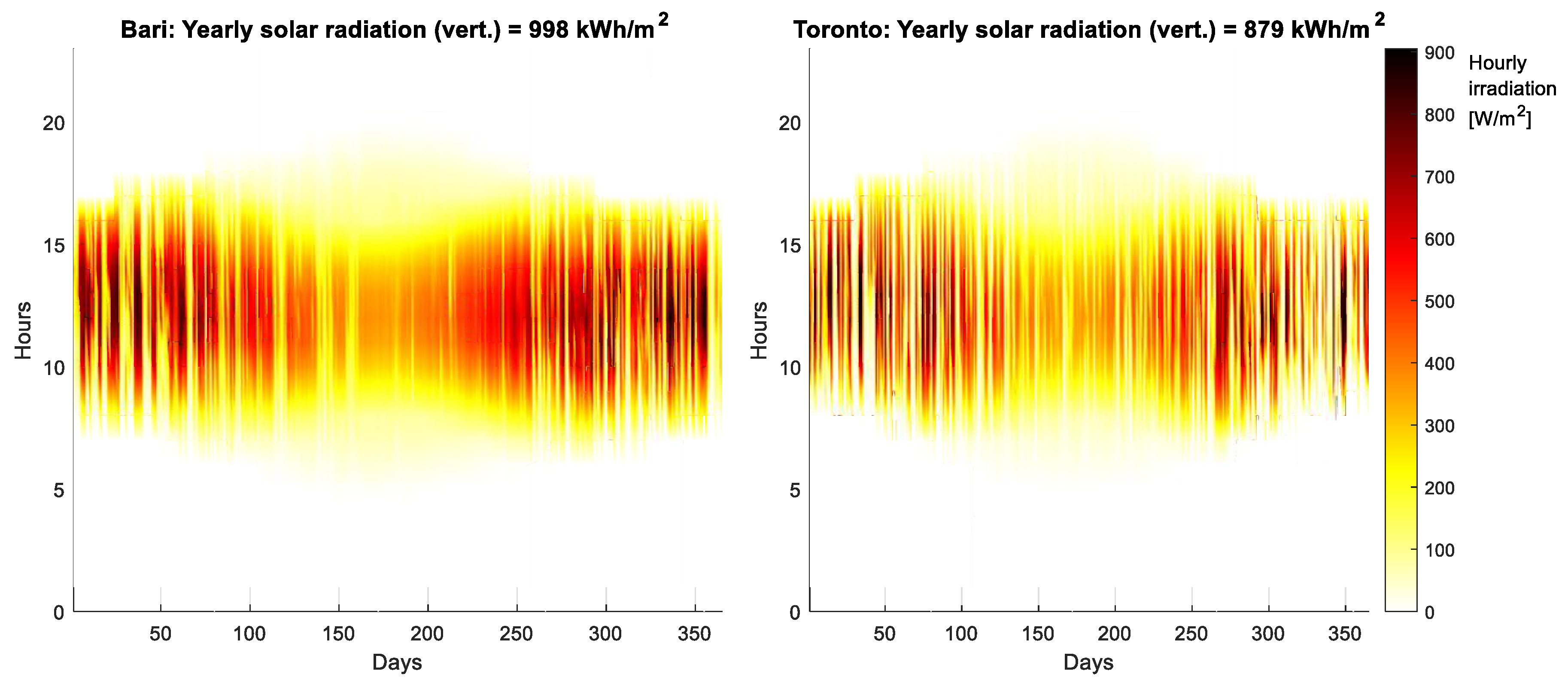
2.3. EnergyPlus Model
3. Results
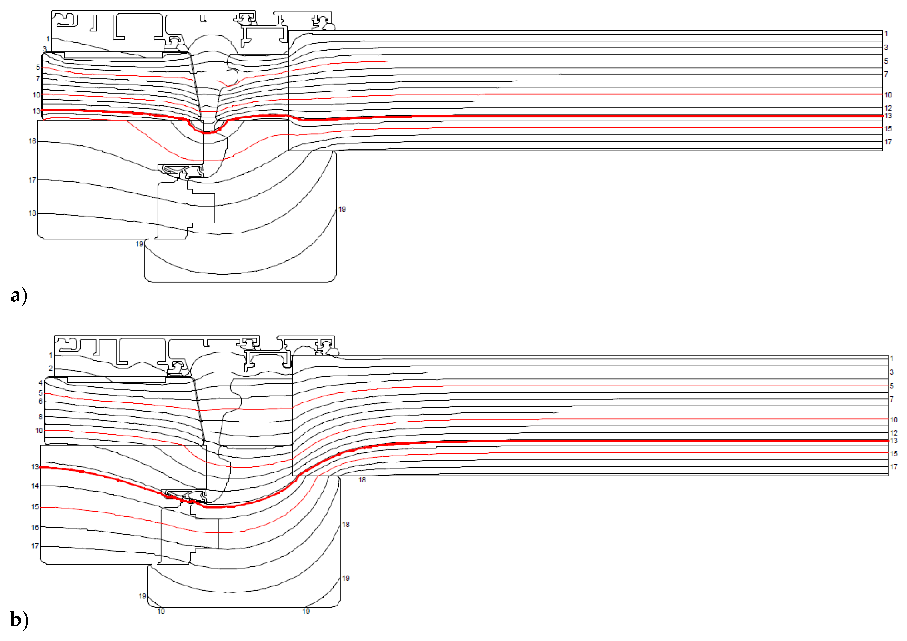
3.1. FEM Model
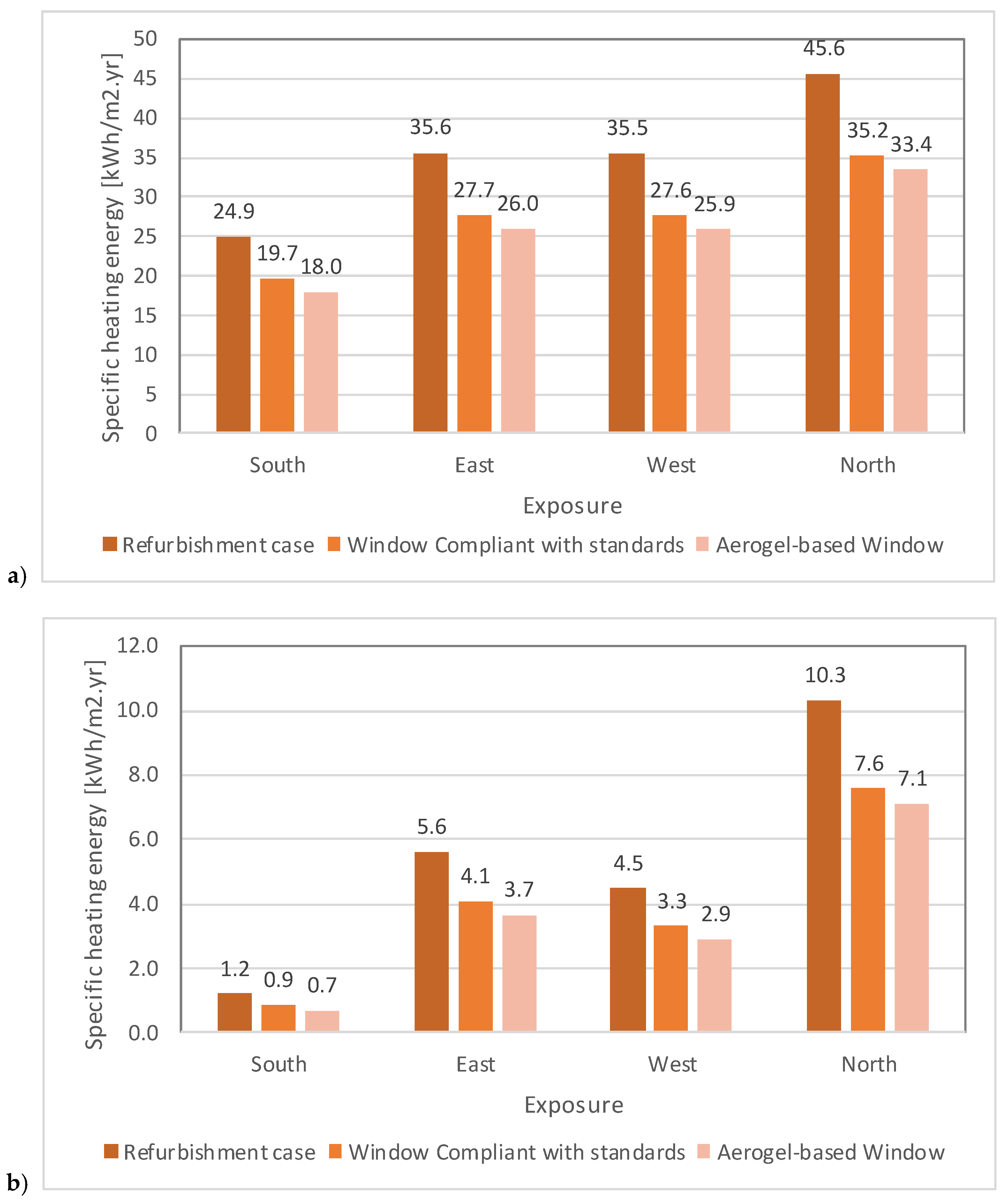
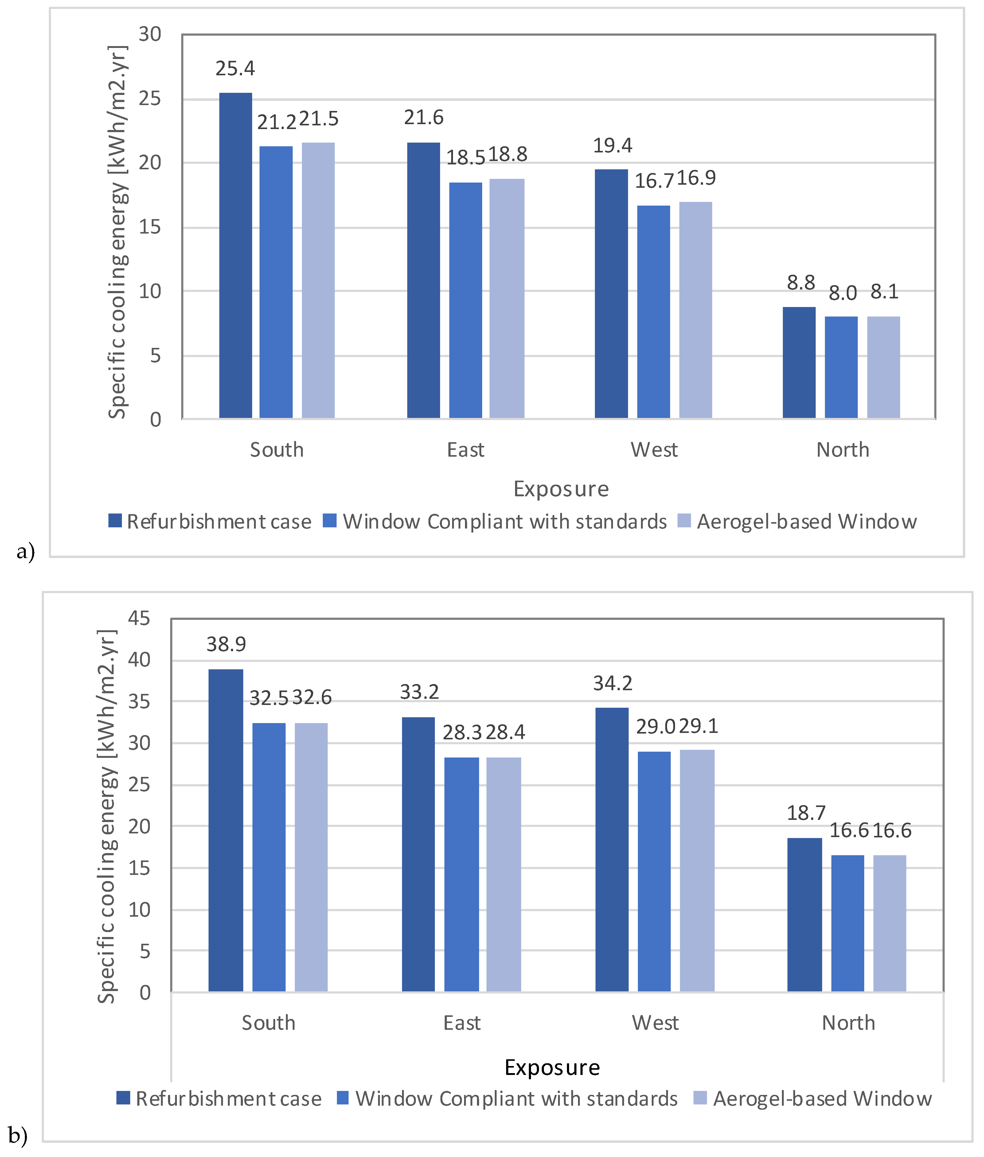
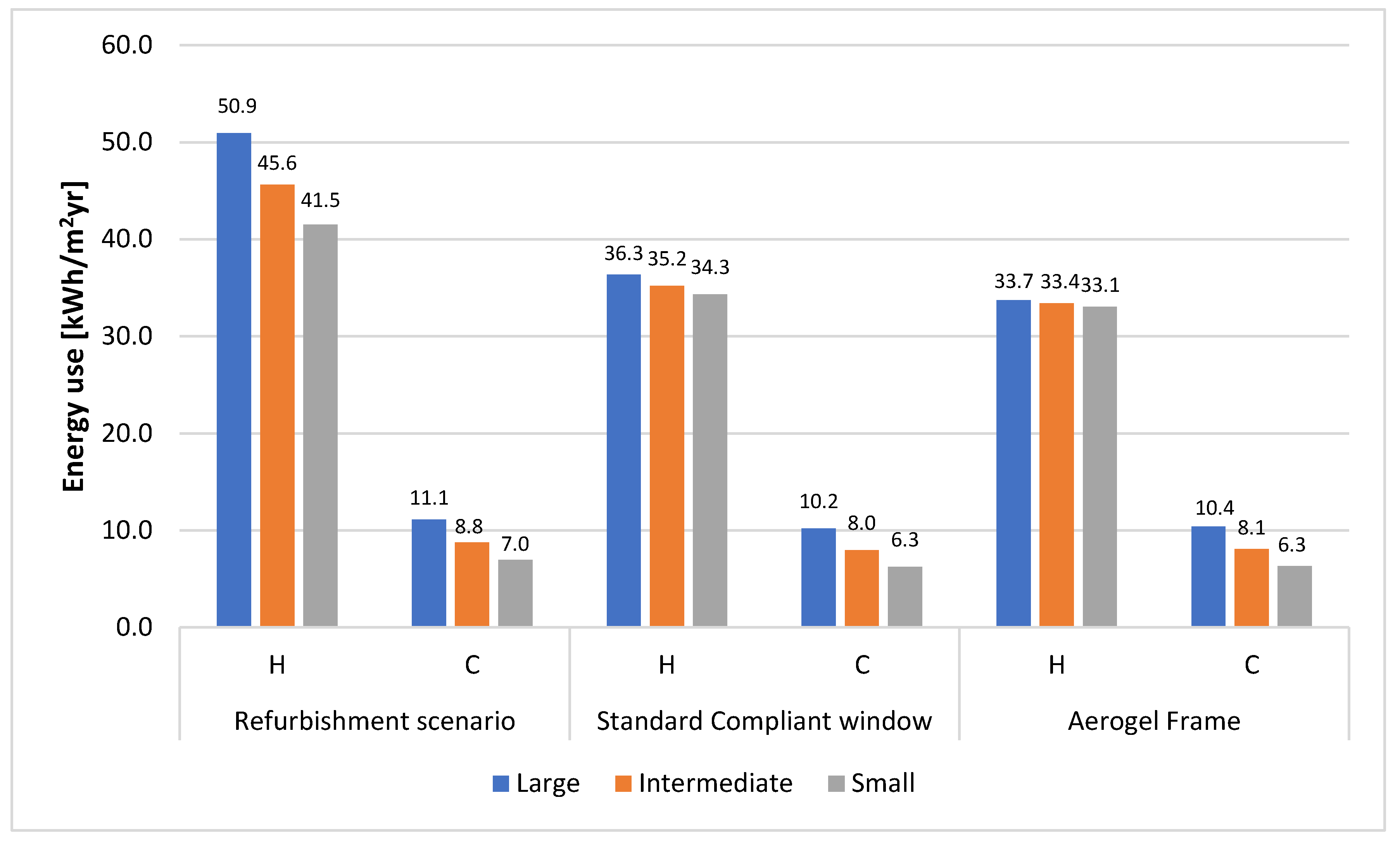
3.2. Energy Consumption
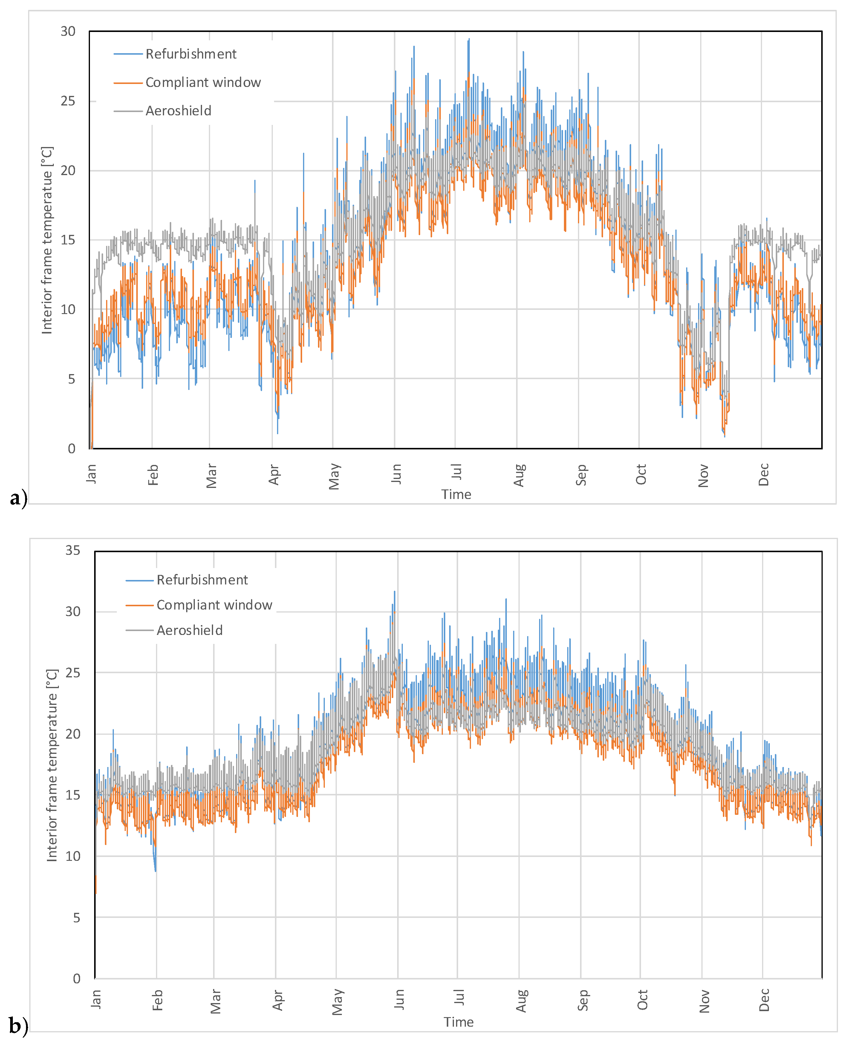
3.3. Frame Temperatures
3.4. North-Facades in Toronto
4. Discussion
5. Conclusions
Author Contributions
Funding
Acknowledgments
Conflicts of Interest
References
- Parliament, E. Directive (EU) 2018/844 of the European Parliament and of the Council of 30 May 2018 Amending Directive 2010/31/EU on the Energy Performance of Buildings and Directive 2012/27/EU on Energy Efficiency. Available online: https://eur-lex.europa.eu/eli/dir/2018/844/oj (accessed on 1 February 2020).
- Wen, R.T.; Arvizu, M.A.; Niklasson, G.A.; Granqvist, C.G. Electrochromics for energy efficient buildings: Towards long-term durability and materials rejuvenation. Surf. Coat. Technol. 2015, 278, 121–125. [Google Scholar] [CrossRef]
- Eperon, G.E.; Burlakov, V.M.; Goriely, A.; Snaith, H.J. Neutral color semitransparent microstructured perovskite solar cells. ACS Nano 2014, 8, 591–598. [Google Scholar] [CrossRef] [PubMed]
- Cannavale, A.; Ierardi, L.; Hörantner, M.; Eperon, G.E.; Snaith, H.J.; Ayr, U.; Martellotta, F. Improving energy and visual performance in offices using building integrated perovskite-based solar cells: A case study in Southern Italy. Appl. Energy 2017, 205, 834–846. [Google Scholar] [CrossRef]
- Jelle, B.P. Traditional, state-of-the-art and future thermal building insulation materials and solutions - Properties, requirements and possibilities. Energy Build. 2011, 43, 2549–2563. [Google Scholar] [CrossRef]
- Berardi, U. Characterization of commercial aerogel-enhanced blankets obtained with supercritical drying and of a new ambient pressure drying blanket. Energy Build. 2019, 198, 542–552. [Google Scholar] [CrossRef]
- De Matteis, V.; Cannavale, A.; Martellotta, F.; Rinaldi, R.; Calcagnile, P.; Ferrari, F.; Ayr, U.; Fiorito, F. Nano-encapsulation of phase change materials: From design to thermal performance, simulations and toxicological assessment. Energy Build. 2019, 188, 1–11. [Google Scholar] [CrossRef]
- Ascione, F.; Bianco, N.; De Masi, R.F.; de’ Rossi, F.; Vanoli, G.P. Energy refurbishment of existing buildings through the use of phase change materials: Energy savings and indoor comfort in the cooling season. Appl. Energy 2014, 113, 990–1007. [Google Scholar] [CrossRef]
- Buratti, C.; Belloni, E.; Palladino, D. Evolutive Housing System: Refurbishment with new technologies and unsteady simulations of energy performance. Energy Build. 2014, 74, 173–181. [Google Scholar] [CrossRef]
- Bahaj, A.S.; James, P.A.B.; Jentsch, M.F. Potential of emerging glazing technologies for highly glazed buildings in hot arid climates. Energy Build. 2008, 40, 720–731. [Google Scholar] [CrossRef]
- Jelle, B.P.; Baetens, R.; Gustavsen, A. Aerogel Insulation for Building Applications. In Sol-Gel Handbook; Wiley-VCH Verlag GmbH & Co. KGaA: Weinheim, Germany, 2015; Volume 3, pp. 1385–1412. [Google Scholar]
- Walker, R.; Pavía, S. Thermal performance of a selection of insulation materials suitable for historic buildings. Build. Environ. 2015, 94, 155–165. [Google Scholar] [CrossRef]
- Cuce, E.; Cuce, P.M.; Wood, C.J.; Riffat, S.B. Toward aerogel based thermal superinsulation in buildings: A comprehensive review. Renew. Sustain. Energy Rev. 2014, 34, 273–299. [Google Scholar] [CrossRef]
- Berardi, U. Aerogel-enhanced insulation for building applications. In Nanotechnology in Eco-efficient Construction (Second Edition), Materials, Processes and Applications; Woodhead Publishing: Cambridge, UK, 2018; pp. 395–416. [Google Scholar]
- Parameshwaran, R.; Kalaiselvam, S. Nano and Biotech Based Materials for Energy Building Efficiency; Pacheco Torgal, F., Buratti, C., Kalaiselvam, S., Granqvist, C.-G., Ivanov, V., Eds.; Springer International Publishing: Cham, Switzerland, 2016; pp. 215–243. ISBN 978-3-319-27505-5. [Google Scholar]
- Buratti, C.; Moretti, E.; Belloni, E. Aerogel plasters for building energy efficiency. In Nano and Biotech Based Materials for Energy Building Efficiency; Springer Nature: Cham, Switzerland, 2016; pp. 17–40. [Google Scholar]
- Ebert, H.-P. Thermal Properties of Aerogels. In Aerogels Handbook; Springer Nature: Cham, Switzerland, 2011; pp. 537–564. [Google Scholar]
- Berardi, U. The development of a monolithic aerogel glazed window for an energy retrofitting project. Appl. Energy 2015, 154, 603–615. [Google Scholar] [CrossRef]
- Neugebauer, A.; Chen, K.; Tang, A.; Allgeier, A.; Glicksman, L.R.; Gibson, L.J. Thermal conductivity and characterization of compacted, granular silica aerogel. Energy Build. 2014, 79, 47–57. [Google Scholar] [CrossRef]
- Ihara, T.; Jelle, B.P.; Gao, T.; Gustavsen, A. Aerogel granule aging driven by moisture and solar radiation. Energy Build. 2015, 103, 238–248. [Google Scholar] [CrossRef]
- Hoseini, A.; McCague, C.; Andisheh-Tadbir, M.; Bahrami, M. Aerogel blankets: From mathematical modeling to material characterization and experimental analysis. Int. J. Heat Mass Transf. 2016, 93, 1124–1131. [Google Scholar] [CrossRef]
- Cuce, E.; Cuce, P.M. The impact of internal aerogel retrofitting on the thermal bridges of residential buildings: An experimental and statistical research. Energy Build. 2016, 116, 449–454. [Google Scholar] [CrossRef]
- Ng, S.; Jelle, B.P.; Sandberg, L.I.C.; Gao, T.; Wallevik, Ó.H. Experimental investigations of aerogel-incorporated ultra-high performance concrete. Constr. Build. Mater. 2015, 77, 307–316. [Google Scholar] [CrossRef]
- Gao, T.; Jelle, B.P.; Gustavsen, A.; He, J. Lightweight and thermally insulating aerogel glass materials. Appl. Phys. A Mater. Sci. Process. 2014, 117, 799–808. [Google Scholar] [CrossRef]
- Berardi, U. Development of glazing systems with silica aerogel. Energy Procedia 2015, 78, 394–399. [Google Scholar] [CrossRef]
- Jelle, B.P.; Hynd, A.; Gustavsen, A.; Arasteh, D.; Goudey, H.; Hart, R. Fenestration of today and tomorrow: A state-of-the-art review and future research opportunities. Sol. Energy Mater. Sol. Cells 2012, 96, 1–28. [Google Scholar] [CrossRef]
- Dowson, M.; Harrison, D.; Craig, S.; Gill, Z. Improving the Thermal Performance of Single Glazed Windows using Translucent Granular Aerogel. Int. J. Sustain. Eng. 2011, 4, 266–280. [Google Scholar] [CrossRef]
- Huang, Y.; Niu, J. Application of super-insulating translucent silica aerogel glazing system on commercial building envelope of humid subtropical climates e Impact on space cooling load. Energy 2015, 83, 316–325. [Google Scholar] [CrossRef]
- Gao, T.; Ihara, T.; Grynning, S.; Petter, B.; Gunnarshaug, A. Perspective of aerogel glazings in energy efficient buildings. Build. Environ. 2016, 95, 405–413. [Google Scholar] [CrossRef]
- Buratti, C.; Moretti, E. Experimental performance evaluation of aerogel glazing systems. Appl. Energy 2012, 97, 430–437. [Google Scholar] [CrossRef]
- Buratti, C.; Moretti, E. Glazing systems with silica aerogel for energy savings in buildings. Appl. Energy 2012, 98, 396–403. [Google Scholar] [CrossRef]
- Valachova, D.; Zdrazilova, N.; Panovec, V.; Skotnicova, I. Using of aerogel to improve thermal insulating properties of windows. Civ. Environ. Eng. 2018, 14, 2–11. [Google Scholar] [CrossRef]
- EnergyPlus 8.9, Building Technologies Program, National Renewable Energy Laboratory (NREL). Available online: https://energyplus.net/ (accessed on 1 July 2019).
- ISO 10077-2:2017 - Thermal Performance of Windows, Doors and Shutters—Calculation of Thermal Transmittance Numerical Method for Frames; Standards Norway. 2017. Available online: https://www.iso.org/standard/64995.html (accessed on 1 July 2019).
- Koebel, M.; Rigacci, A.; Achard, P. Aerogel-based thermal superinsulation: An overview. J. Sol-Gel Sci. Technol. 2012, 3, 315–339. [Google Scholar] [CrossRef]
- Bhagat, S.D.; Kim, Y.-H.; Moon, M.-J.; Ahn, Y.-S.; Yeo, J.-G. A cost-effective and fast synthesis of nanoporous SiO2 aerogel powders using water-glass via ambient pressure drying route. Solid State Sci. 2007, 9, 628–635. [Google Scholar] [CrossRef]
- Koebel, M.M.; Huber, L.; Zhao, S.; Malfait, W.J. Breakthroughs in cost-effective, scalable production of superinsulating, ambient-dried silica aerogel and sili-ca-biopolymer hybrid aerogels: From laboratory to pilot scale. J. Sol-Gel Sci. Technol. 2016, 79, 308–318. [Google Scholar] [CrossRef]
- Wu, X.; Fan, M.; Mclaughlin, J.F.; Shen, X.; Tan, G. A novel low-cost method of silica aerogel fabrication using fly ash and trona ore with ambient pressure drying technique. Powder Technol. 2018, 323, 310–322. [Google Scholar] [CrossRef]


| Window Type | Glazing Structure | Glass U-Factor (W/m2∙K) | Frame and Divider Conductance (W/m2∙K) | Low-e Coating | Frame Materials |
|---|---|---|---|---|---|
| Refurbishment scenario | 4/16/4 | 2.60 | 7.57 | - | Aluminium without thermal break |
| Standard Compliant scenario | 4/16/4/16/4 | 1.08 | 3.5 | Face 5 | Aluminium with thermal break |
| City | Latitude [°] | Koppen-Geiger Climate Class | Average Temperature [°C] | Winter Average Temperature [°C] | Winter Average Daily Minimum Temperature [°C] | Winter Average Daily Maximum Temperature [°C] |
|---|---|---|---|---|---|---|
| Toronto | 43.70 | Dfb | 9.85 | −3.00 | −6.53 | 2.60 |
| Bari | 41.11 | Csa | 16.10 | 9.87 | 6.27 | 13.57 |
| Window Size | WWR (%) | FGR (%) | Window Surface Area (m2) | Frame Surface Area (m2) | Normalized Yearly Energy Consumption (kWh/m2⋅yr) | ||
|---|---|---|---|---|---|---|---|
| Refurbishment | Standard-Compliant | Aerogel-Insulated | |||||
| Small | 43 | 39 | 5.3 | 2.0 | 221.6 | 166.3 | 157.5 |
| Intermediate | 60 | 42 | 7.3 | 3.0 | 362.6 | 287.8 | 276.5 |
| Large | 100 | 46 | 12.2 | 5.6 | 484.7 | 405.7 | 393.8 |
© 2020 by the authors. Licensee MDPI, Basel, Switzerland. This article is an open access article distributed under the terms and conditions of the Creative Commons Attribution (CC BY) license (http://creativecommons.org/licenses/by/4.0/).
Share and Cite
Cannavale, A.; Martellotta, F.; Berardi, U.; Rubino, C.; Liuzzi, S.; De Carlo, V.; Ayr, U. Modeling of an Aerogel-Based “Thermal Break” for Super-Insulated Window Frames. Buildings 2020, 10, 60. https://doi.org/10.3390/buildings10030060
Cannavale A, Martellotta F, Berardi U, Rubino C, Liuzzi S, De Carlo V, Ayr U. Modeling of an Aerogel-Based “Thermal Break” for Super-Insulated Window Frames. Buildings. 2020; 10(3):60. https://doi.org/10.3390/buildings10030060
Chicago/Turabian StyleCannavale, Alessandro, Francesco Martellotta, Umberto Berardi, Chiara Rubino, Stefania Liuzzi, Vincenzo De Carlo, and Ubaldo Ayr. 2020. "Modeling of an Aerogel-Based “Thermal Break” for Super-Insulated Window Frames" Buildings 10, no. 3: 60. https://doi.org/10.3390/buildings10030060
APA StyleCannavale, A., Martellotta, F., Berardi, U., Rubino, C., Liuzzi, S., De Carlo, V., & Ayr, U. (2020). Modeling of an Aerogel-Based “Thermal Break” for Super-Insulated Window Frames. Buildings, 10(3), 60. https://doi.org/10.3390/buildings10030060