1. Introduction
In general, steel bar structures are determined as spatial structures made of slender members which are directly connected in order to carry loads. Historically, curvilinear steel bar structures, mostly in the form of cylindrical lattice structures, began to be created in the mid-nineteenth century. However, due to serious difficulties in both calculating and constructing from repeatable elements, they began to be used on a larger scale only in the 1940s. During this period, the beginning of steel mass production and the invention of many devices influenced the great development of various manufacturing technologies of steel roof structures. The most popular were layered geodesic domes, which were shaped using the procedures of sphere division into triangles elaborated by Buckminster Fuller [
1,
2]. Due to this fact, the problem of the most regular subdivision of the spherical surface was one of the major challenges for scientists in the steel structures field. Various ways of dividing a sphere have been developed over the years, in order to achieve different types of grid, like Lamell’s lattice and Schwedler’s lattice [
3]. However, combining different parts of the sphere into larger forms was one of the ways of obtaining new shapes of grid shells [
3]. The broad review of various types of spatial grid structures and their development is described in [
4], whereas broad analytical approaches concerning plane bar grids and double layer trusses are given in [
5]. The method of forming steel bar structures, placing their vertices on the so-called base surfaces which are Catalan surfaces—has been presented in [
6]. On the other hand, the shaping of bar structures based on minimal surfaces, especially the Enneper surfaces, is presented in [
7,
8].
A hyperbolic paraboloid constitutes an especially interesting and important basic shape for various single or complex architectural roof forms. The use of a hyperbolic paraboloid shape for constructing thin shells was pioneered in the post-war era as the result of the combination of modern architecture with structural engineering. The hyperbolic paraboloid as the element for creating complex forms was used widely by F. Candela for the implementation of lightweight shell concrete structures, constituting coverings that are free of intermediate supports [
9]. The great interest in this shape was caused by its positive static properties, allowing the creation of shells with a large span, as well as a great possibility of various arrangements of single shells in compound ones.
Hyperbolic paraboloids are exceptionally stiff, due to their double curvature [
10]. They exhibit membrane action, wherein internal forces are efficiently transmitted through the surface, which is the subject of various publications [
11,
12]. Most of the research concerns theoretical, experimental and constructional problems related to hyperbolic paraboloid concrete or reinforced concrete shells [
9,
13]. The method of shaping freeform buildings, roofed with profiled steel sheets effectively transformed into strips of screw ruled surfaces, is presented in [
11,
14]. However, the behaviour of gabled hyperbolic paraboloid shells is studied in [
15]. Although a hyperbolic paraboloid as a ruled surface constitutes a good basis for creating lattice grids, there is little research into the effect of the division of this surface, as well as received grid pattern, on the bearing capacity of the bar structure created. However, the variety of compound roof structures that can be obtained by combining several hyperbolic paraboloid grid modules is presented in [
12]. The canopy roofs of hyperbolic paraboloid shape are worth considering due to both their interesting form and relative simplicity of construction.
At present, the use of curvilinear steel bar structures is increasing thanks to advanced technology in the field of steel bar structures. Thus, more and more curvilinear steel bar structures are created, with a great variety of geometric forms and technical solutions. Therefore, a rational and effective attempt to shaping of this type of structures is important. The shaping phase is the design phase preceding all subsequent stages of the design process, which is why it is the most creative phase, as well as having a significant impact on the final form of the structure [
9,
16]. Due to this fact, it is very important to consider as many aspects of the future project as possible in the early stage. The principles of the rational shaping of steel bar structures are presented in many publications [
17,
18]. However, shaping the curvilinear steel bar structures can sometimes be a challenging task.
The possibilities of rational shaping depend not only on creativity and practical skills, but also on the design tools used. In the last twenty years, the progress of digital technologies has affected the entire field of both architectural design and structural engineering. That is due to the fact that digital tools greatly facilitate the creation of complex geometry, as well as performing advanced structural calculations [
19]. The practical application of the digital design tools by European design studios is presented in the research reported in [
20]. Various computer-aided design (CAD) tools enable both the creation of two-dimensional documentation and the creation of three-dimensional models based on two-dimensional drawings [
21,
22,
23]. CAD technology enabled the generation of digital models, their geometry visualization and, finally, analysis of their structural behavior. Moreover, the progress in design caused by development of computer technology and integration of digital modeling systems has facilitated cooperation in various design areas, such as architecture and structural engineering [
24,
25]. Especially, in the field of steel bar structures, whose shaping is accompanied by a number of issues, the interdisciplinary approach is often required.
Recently, development of the modeling process based on Non-Uniform Rational B-Splines (NURBS) has had a great impact on forming the structures’ shapes. NURBS can be controlled during modeling, and therefore they can constitute a base for the generation of various digital changeable forms with diverse topologies. Moreover, digital environment, especially algorithmic-aided shaping structures, has created new possibilities for performing various simulations, which further enable structural optimization [
26]. In 1977, the idea of solving evolutionary optimization problems was introduced by means of a computer simulation of evolutionary transformations [
27]. The evolutionary algorithms for such a simulation are the stochastic search methods that mimic natural biological evolution. These algorithms have been developed in order to arrive at near-optimum solutions to large-scale optimization problems for which traditional mathematical techniques might fail [
28]. A comparison of the formulation and results of five recent evolutionary-based algorithms—genetic algorithms, particle swarm algorithms, ant-colony systems, and shuffled frog leaping—is presented in [
28].
The algorithms presented in the paper are genetic algorithms inspired by Darwin’s theory of evolution, which mimic natural selection and gene mutation. In each genetic algorithm, the optimization process of the given problem begins with creating a set of random solutions called individuals. The set of variables is treated as chromosomes. As in nature, the whole set of possible solutions is considered a population. The most efficient and strong chromosomes are selected in order to create the next population. The evolutionary principles of genetic algorithms allow the generation of well-performing instances and search for the solution closest to the optimal one in the given space [
29]. In order to solve the optimization problem, the parameters and constraints of the problem should be identified. Depending on the nature of the objective function applied, the optimization problem can be classified into either single objective or multi objective. In the literature of the subject, the term multi-objective optimization refers to problems with up to four objectives [
27].
The optimization of bar structures can deal with many aspects: the weight of the structure, appropriate support method, or topology related to both ultimate limit states (ULS) and serviceability limit states (SLS) [
6,
8,
30,
31]. In the case of a steel structure analyzed in the paper, the ultimate limit state referring to internal failure involves the resistance of cross sections and the resistance of the structure and its members. If the design value of effect of actions
Ed does not exceed design value of corresponding resistance
Rd, then this should be verified. The design value of the effects of actions
Ed is determined by combining the various values of actions that are considered to occur simultaneously.
However, verification of SLS primarily aims at preventing excessive movements or vibrations of structures [
31]. Whether the design value of the effects of actions specified in the serviceability criterion
Ed does not exceed limiting design value of the relevant serviceability criterion (e.g., design value of displacement) should be verified.
In the paper, the effects of displacements and deformations are mostly taken into account, assuming deflection limits equal to
where
L–span of the structure [
31].
The application of evolutionary structural optimization (ESO) for the shaping of steel bar structures is a new field of research, which can lead to obtaining effective structures.
Referring to the above conditions, the article attempts the multi-objective optimization of curvilinear steel bar structures forming roofs of hyperbolic paraboloid shape. Although the hyperbolic paraboloid as a ruled surface may be a convenient base for forming bar grids, there are few studies on the effect of its division and the topology of the obtained bar structures on their load-bearing capacity. In order to fill this gap, the aim of the presented research is the comparison of the effectiveness of canopies—curvilinear steel bar structures formed based on hyperbolic paraboloids covering the same plane. The research goal is to determine the most effective pattern of grids and the optimal supporting system, as well as the mass of the structure.
2. Materials and Methods
The research was conducted with the application of modern digital tools working in Rhinoceros 3D software developed by Robert McNeel and Associates [
32]. These tools are: Grasshopper plug-in for parametric modeling and Karamba 3D plug-in developed to predict the behaviour of structures under external loads [
33]. The active use of Rhinoceros 3D/Grasshopper software in the architectural design process is becoming increasingly popular in the world, mainly as a tool for generating models with complex geometry. Moreover, interactive structural evolutionary optimization has recently gained some popularity for optimization in structural design [
6,
8,
9,
34]. New methods of design solutions based on genetic optimization are analyzed in [
35]. However, algorithmic structural shaping, which is the process in which both the geometric model and structural analysis are carried out using multi-objective interactive structural evolutionary optimization algorithms, is a new field of research. Therefore, the approach presented in the paper to shape curvilinear steel bar structures of hyperbolic paraboloid canopy roofs is innovative.
During the tests, in order to generate geometric models, Rhinoceros 5.0 version was used in combination with Grasshopper. This enabled the creation of complex generative algorithms and the parallel exploration of the shaped geometric models in the Rhinoceros 3D viewport. The shaping strategy presented in the paper consisted of forming of curvilinear steel bar structures by placing their structural nodes on the so-called base surfaces, which were hyperbolic paraboloids. However, the structures’ geometries were generated algorithmically using a set of various specified input parameters.
Then, on the basis of the created geometric models of the analyzed structures, as well as the adopted boundary conditions concerning the supporting systems (loads), as well as the type of joins and material properties, the structural models were established. The integration of geometrical shaping and structural analysis took place by the Karamba 3D. The topology and cross-sections of the structures’ bars were optimized taking into account the minimal structure’s self-weight, as well as minimal deflection, as the optimisation criteria.
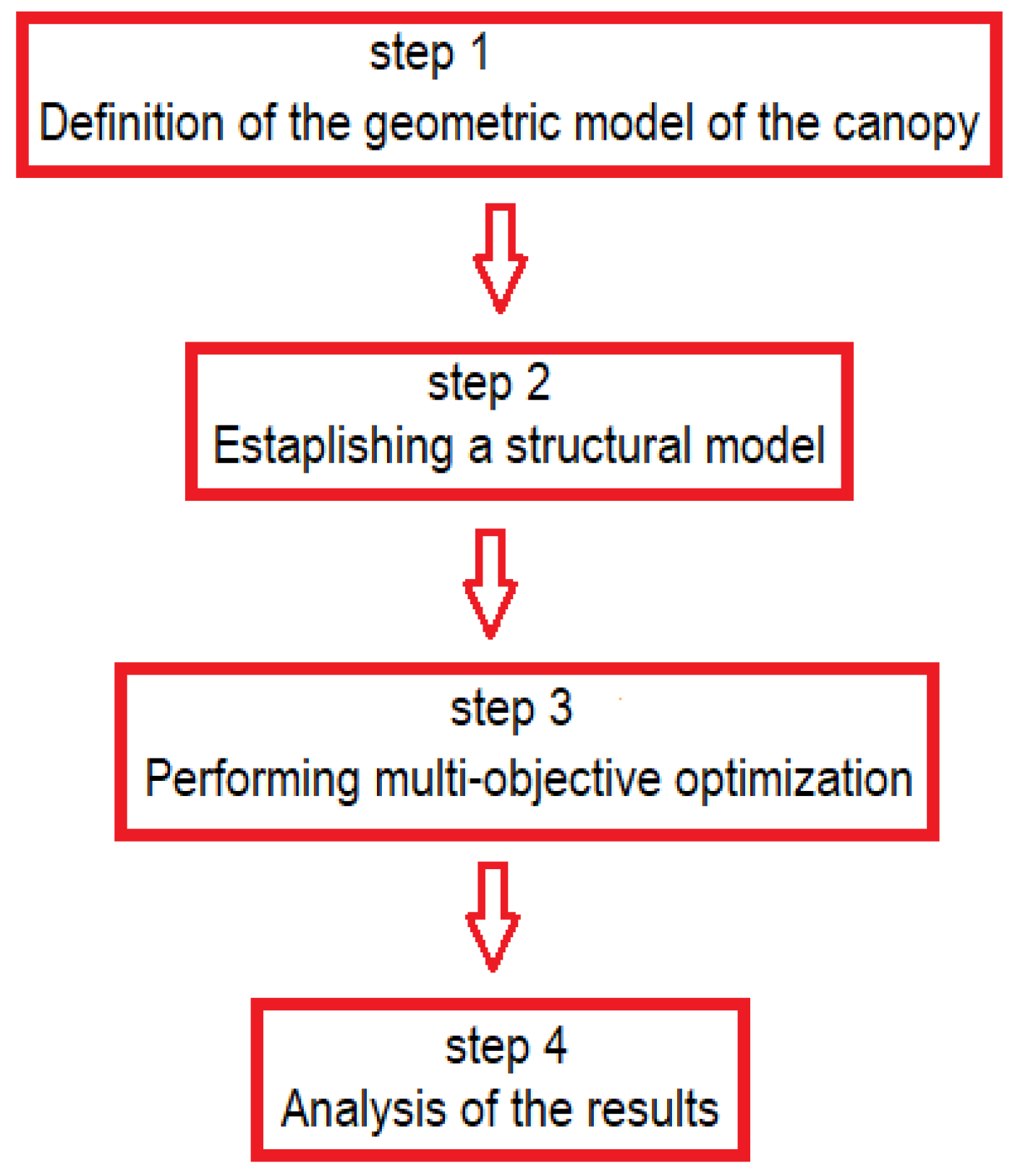
The general scheme of the conducted analysis dealing with shaping hyperbolic paraboloid canopy roof is presented in
Figure 1. However, a more detailed description of the individual steps is provided in the following sections.
2.1. Definition of the Geometric Model of the Canopy
Canopy roofs of hyperbolic paraboloid shape were chosen as a case study. It was assumed that the roofs covered a square plan of an area of 100 square meters. Each roof was supported by four columns placed symmetrically, whereas each column was joined with the grid by four branches,
Figure 2. The positions of the columns have been set as parametric variables, as well as the locations of the branches’ nodes.
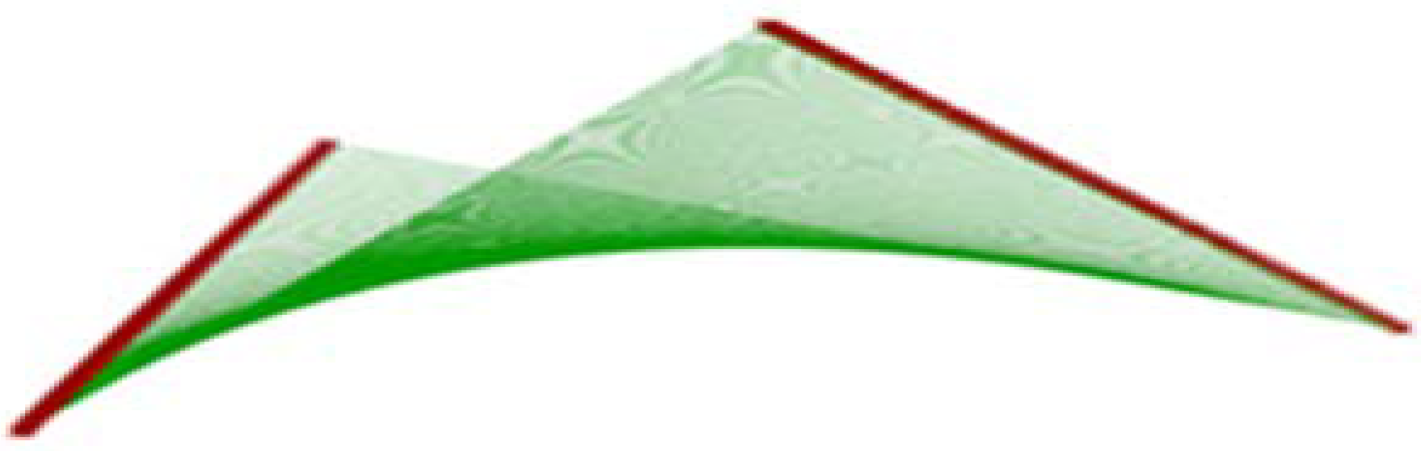
The hyperbolic paraboloid roof surface as the ruled surface was established by two skew lines—the directrix lines and a director plane to which all surface’s rulings are parallel,
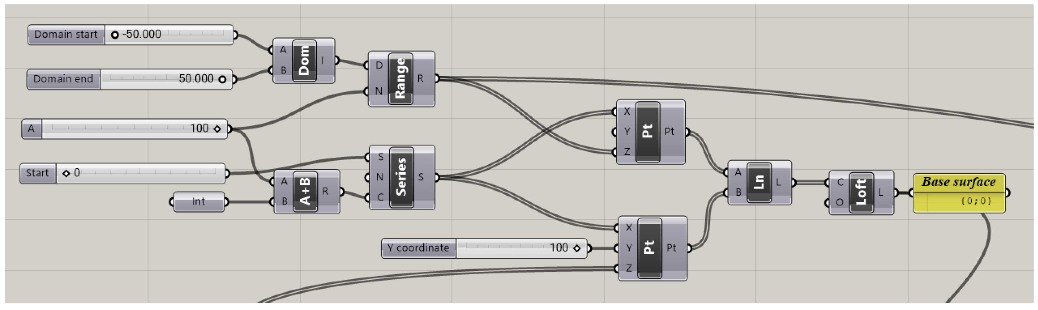
Figure 3. This surface constituted the base surface to form a grid of bars.
The Grasshopper’s algorithm, composed of the connected block components, was created in such a way that two skew lines defined parametrically by two pairs of various points were distinguished as its input. Each of the lines were next divided into the same number of elements to establish a series of points on them. These series of points were next joined by lines to define a hyperbolic paraboloid, which constituted a base surface for structural grid creation. Therefore, the obtained surface was discretized by dividing it into the same number of parts in two directions. Thanks to this a three-dimensional quadrate grid was obtained, whose vertices lay on the base surface. The Grasshopper’s block script for roof’s base surface creation is presented in
Appendix A,
Figure A1.
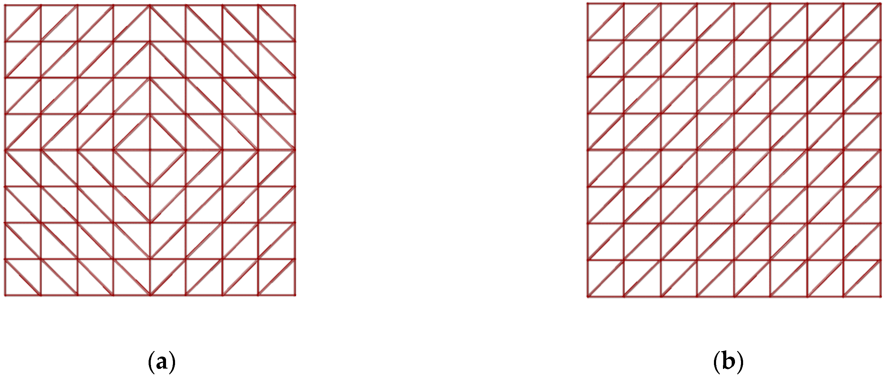
Next, each spatial polygon of the obtained grid was divided into two triangles to form a triangular bar grid. Depending on the division direction of each of the quadrangles, which can be done along shorter or longer diagonals, and depending on the number of subdivisions of the base surface as well as its type, various patterns of bar grids can be obtained. In
Figure 4, the examples of grid patterns obtained due to eight-fold division of the hyperbolic paraboloid surface are shown. The structure with the grid pattern split along a short diagonal is further called the structure of type a in the paper, whereas the structure with the grid pattern split along a long diagonal is called the structure of type b.
The geometry of each considered structure was determined using a block algorithm with variable parameters. However, during the simulations carried out, the following variables were adopted:
The amount of parts into which the surface was divided or the lengths of grid bars, which determined the division;
The distances of the branches’ nodes from the ground;
The locations of the supports expressed by the distances of the column bases from the borders of the covered square,
Figure 5.
Moreover, it was assumed that each branch node was placed at the column’s end point, whereas the column length was equal to a distance of between sixty and eighty percent of the distance of the ground support from the roof surface. However, the columns were assumed to be located within the rectangular plan, but no further than one meter from the place’s border (offset from the edge of the square in both
x and
y directions of 0.0–1.0 m),
Figure 5.
2.2. Establishing of the Structural Model of the Canopy and Assumptions for the Evolutionary Optimization
Due to the fact that the geometry of the structure plays a crucial role in any optimization problem, the scripts developed to achieve the geometric forms of the roof structures were used as the part of the scripts defining the structural models for optimization performed by Karamba 3D. For that reason, grid lines were changed into beams, whereas grid vertices were changed into structural nodes. The assumed boundary conditions regarding the means of support, as well as both joints and material properties, were specified too. The structure was assumed to consist of round steel pipes. The structural nodes of the grid were assumed to be rigid, while the branches’ joins with the grid as pinned joins. For a roof covering, polycarbonate plastic panels with a thickness of 10 mm were chosen.
The optimization was performed by Octopus which is the Grasshopper’s plug-in for applying evolutionary principles to parametric design and problem solving by multi-objective optimization. Octopus as an evolutionary simulator can approach optimal solution sets through iterative tests and constant self-adaptation. It possesses the ability to cross-reference multiple parameters simultaneously. However, it requires multiple objectives to be input.
The goal of the performed optimization was to determine the best structure in terms of bar grid topology, the location of supports, and the locations of branches’ nodes. However, the optimization objectives were as follows:
Minimize total mass m;
Minimize deflection d.
Structural constrains resulting from general structural principles presented in [
31,
32,
33,
34,
35,
36] were as follows:
Due to ULS, the structure should be able to bear acting loads, but this verification was carried out automatically;
Due to SLS, the deflection limit for any load case should fulfill the condition f = L/250, where L is a span of the structure, so for considered structures, f ≤ 40 mm;
Kind of structural material applied: steel S235.
Established variables:
Dimensions of the rectangular plan—10 m × 10 m;
Number of supports—four;
The height of the whole structure—5 m;
The height of the roof’s surface—2 m;
Elements’ cross sections—circular hollow, walls’ thickness not less than 3.2 mm.
Variables for optimization:
Location of the supports—within the rectangular plan, however, no further than one meter from the place’s border;
Bars’ length: 1.0–3.0 m;
Location of the column branching node in the scope of 60–80%d, where d is the distance of the column’s base to the roof’s surface.
During simulations it was assumed that the structures were composed of round tubes with cross-sections, as expressed in
Table 1.
Moreover, it was assumed that each structure is loaded by its self-weight, as well as environmental loads from snow and wind. The wind load was applied locally to the grid structure whereas snow wind was applied globally. These loads were calculated in the form of pressure coefficients acting over the surface of the roof assuming the structure’s location in Rzeszow, Poland [
34,
36]. Several combinations of loads have been considered, including asymmetric ones, which, in the case of canopy roofs, can be crucial when shaping the structures. However, in this case, the worst case scenario was achieved for the combination when the drifted snow load is a main load and the wind load is an associated load acting from above on the structure.
Due to the symmetry of each roof structure and its shape, some simplifications were proposed; that is, the snow load could be calculated similarly, as in the case of a butterfly roof, whereas roof inclination angle was determined according to
Figure 6.
3. Result
The simulation was carried out four times: twice for structures with the grid pattern of type a and twice for structures with the grid pattern of type b, presented in
Figure 4. The first simulation for both structures was carried out assuming bar lengths within the scope of 1.5–2.0 m, while the second one assumed bar lengths within the scope of 1.0–3.0 m.
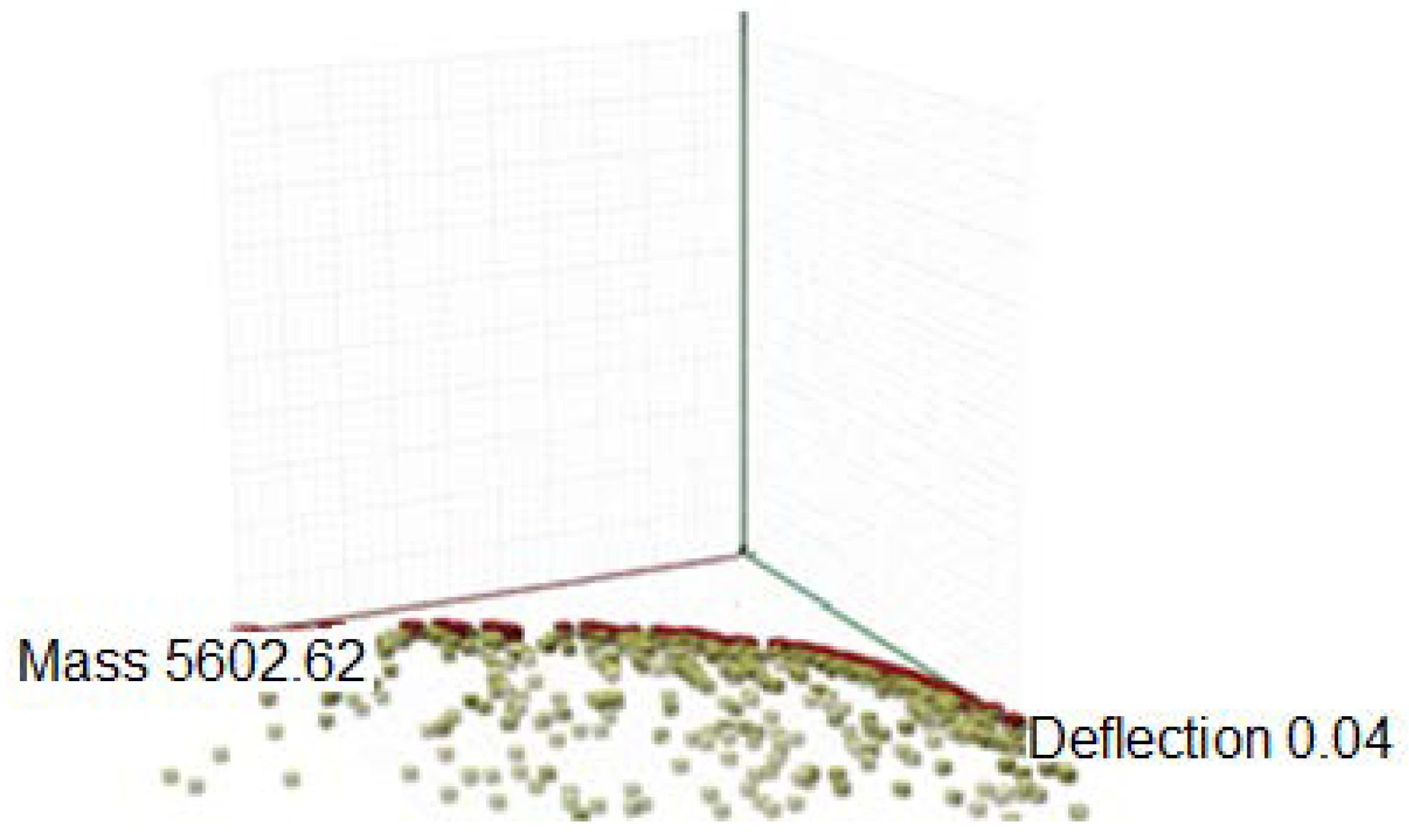
Due to the fact that the optimization objectives indicated previously—the minimization of total mass and minimization of deflection—are conflicting, several results of each simulation for both structures with pattern a and b have been chosen. The graph of the Pareto front with the best solutions for the structure of type
a received during the first simulation is presented in
Figure 7. The individuals that are displayed closest to the origin are equally optimal for all three objectives, however, in our case solutions which meet both ULS and SLS were chosen. As was mentioned earlier, ULS and SLS are verified automatically. However, deflection cannot exceed 0.04 m. The generated solutions are characterized by the fact that the greater the mass of the structure, the smaller the deflection. Therefore, several solutions were chosen for which the deflections are close to but not exceeding 0.04 m. This guarantees the minimum mass of the structure.
The chosen results of the first simulation performed for the structure of type a (grid split along a short diagonal) are given in
Table 2. However, the results of the simulation performed for the structure of type b (grid split along a long diagonal) are given in
Table 3.
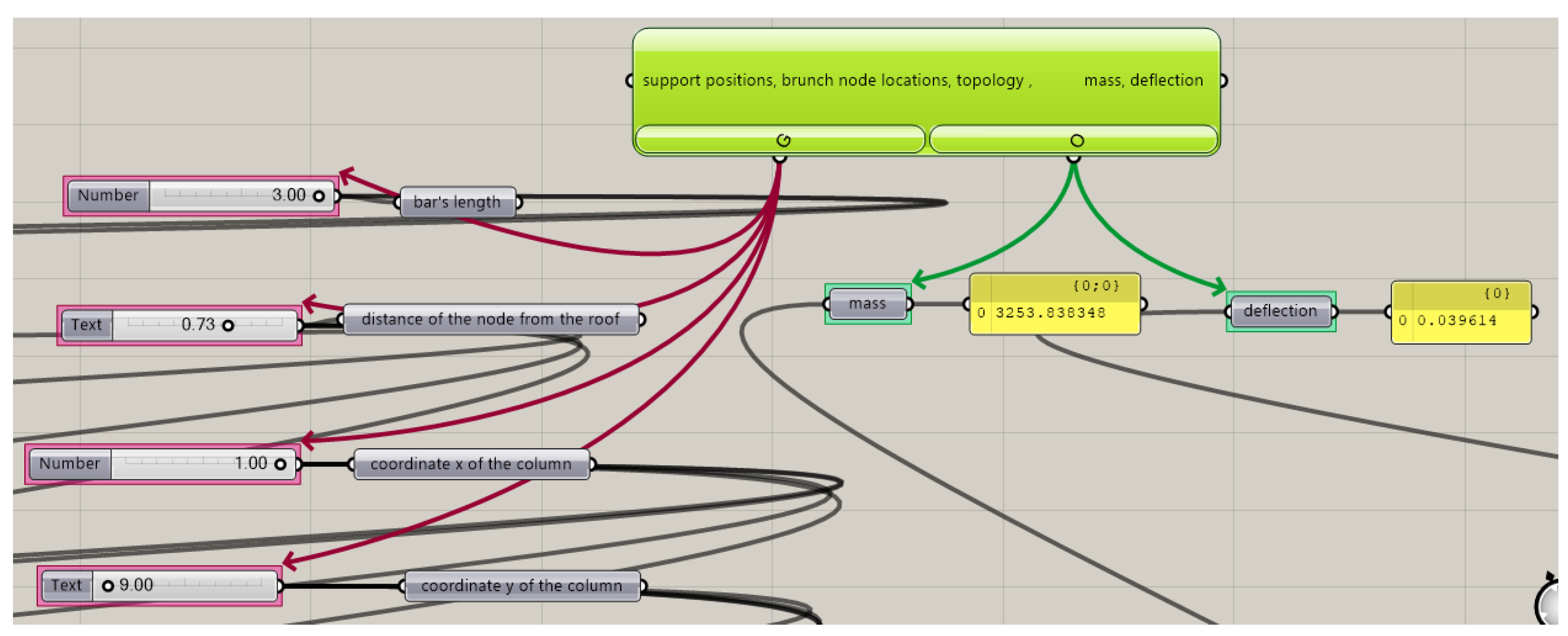
It is worth noticing that the achieved bar grids during the first simulation were obtained as a result of the division of the surface into eight parts in both directions. Due to the smallest mass, the structure a1 is the most efficient,
Figure A2.
During the second simulation, a maximum bar length of 3 m was allowed and bar grids were obtained as a result of the division of the surface into four parts in both directions. The Pareto front for the structure type b is presented in
Figure 8. However, several solutions of the simulation assuming bar lengths within the scope of 1.0–3.0 m are presented in
Table 4 and
Table 5.
The analysis of the above results suggests that there was a certain reserve in the amount of deflections in the structure, which created the possibility of reducing bars’ cross-sections. Therefore, another simulation was performed assuming bars’ cross-sections as in
Table 6.
The results of this simulation for structures of type a and type b are given in
Table 7 and
Table 8, respectively. However, the optimum results generated due to performed simulation are presented in
Figure A3 and
Figure A4.
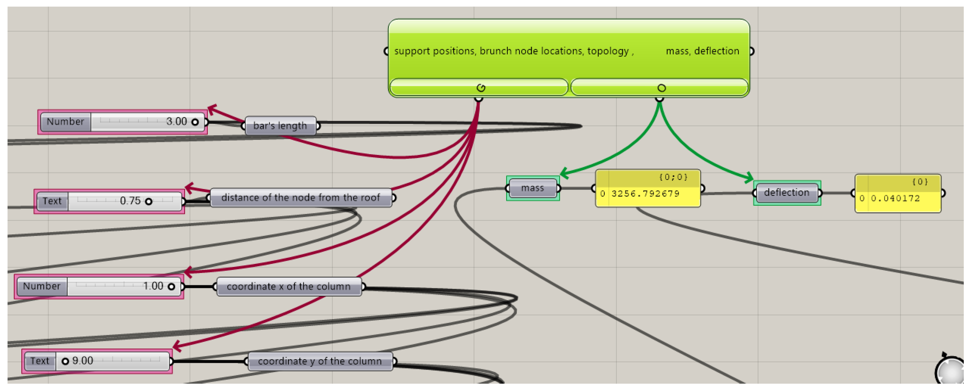
On the basis of the above, the results of the most efficient structure resulted in the structure a1, presented in
Figure 9.
4. Discussion
An original algorithmic-aided method of shaping the hyperbolic paraboloid canopy roof structures has been proposed. This method verifies simulation structures’ geometries with respect to structural requirements. The performed analyses found several solutions that meet ULS at given boundary conditions and, at the same time, meet SLS, i.e., do not exceed the allowable deflection of 40 mm. Based on the results compiled in the tables T2, T3, T4, T5, T7, T8, it can be concluded that the mass of the considered structure depends on the grid topology. In turn, this topology is dependent on the method of surface division, as well as the number of divisions applied. The curvilinear steel bar structures resulting from the division of the hyperbolic paraboloid into four parts are much lighter than the structures resulting from the division into eight parts. Due to the fact that the weight of the structure significantly affects its cost, these structures are more effective.
As previously mentioned, triangular grids of curvilinear steel bar structures analyzed in the study are obtained by dividing spatial quadrate grids, and the division can take place along the longer diagonals or shorter ones. The research revealed large differences in the masses of the structures depending on the shaping of triangular grids based on quadrangular grids. The analysis of the structures carried out showed that the grid structures obtained by dividing quadrangles along the longer diagonals are much heavier than the grid structures formed when dividing them along shorter diagonals.
The location of the supporting columns is another aspect that has a significant impact on the efficiency of the structure. The simulations showed that the further the columns are moved away from the edge of the covered square, the larger the mass of the structure. Moreover, the research found the optimal branch node positions, and thus the optimal column lengths for each structure.


