1. Introduction
In Italy, the dairy sector is recognized as one of the most impacting agricultural activities, with important economical revenues, having a relevant and growing role in the agri-food economic sector. As it is well-known, Grana is a type of Italian hard, mature cheese with a granular texture, often used grated, typically proposed in the form of large wheels. The most famous examples of grana-type cheeses are Parmigiano-Reggiano, Grana Padano and Trentin-Grana. The great taste of Grana is created through a slow, natural ageing process in specifically designed maturation warehouses at constant and monitored temperature and humidity for a period generally comprised between 12 and 40 months. These warehouses are typically formed by modular steel rack frames contained inside reinforced concrete buildings.
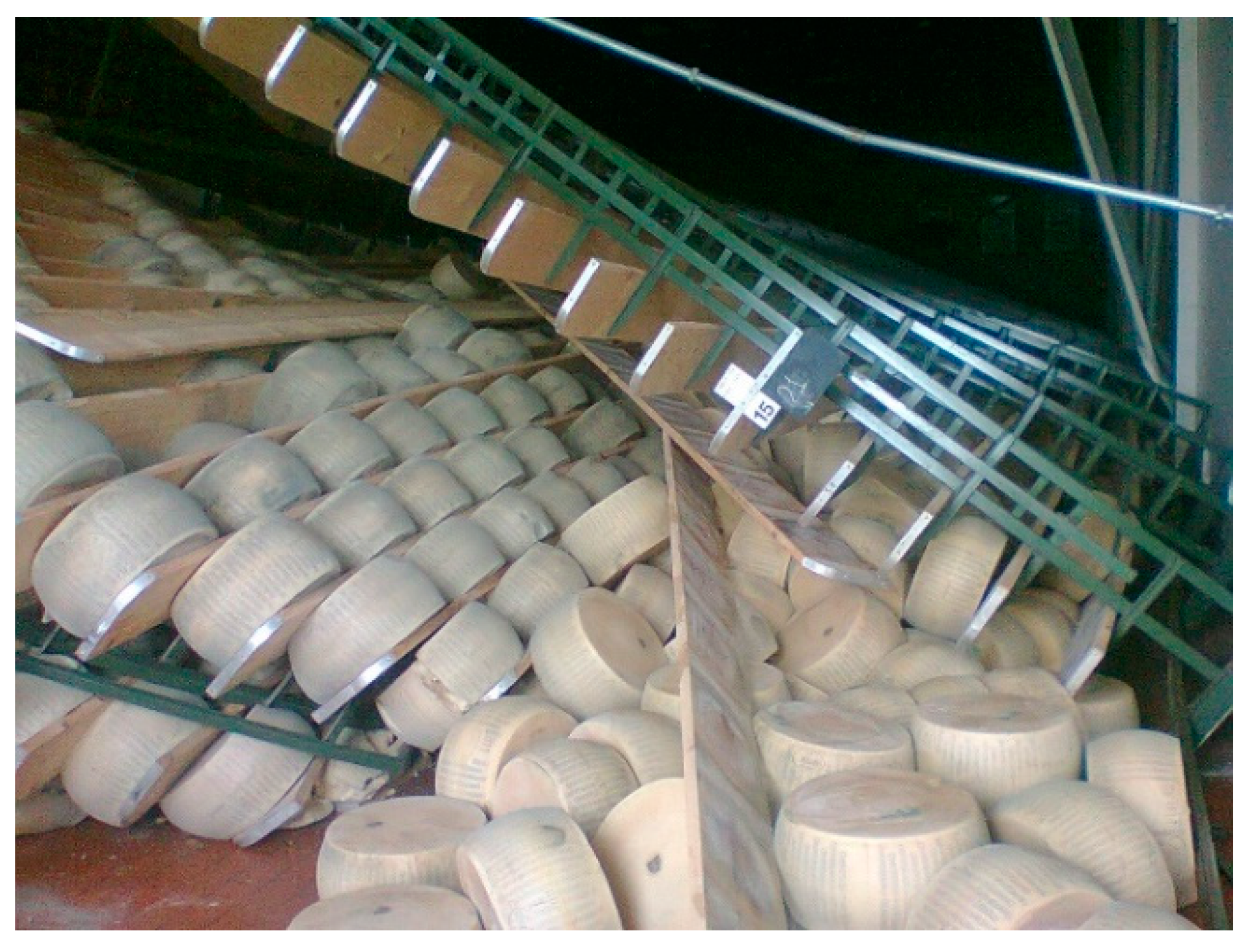
Earthquakes occurred in May 2012 in Emilia Romagna (Italy) caused in few cases severe damages to grana warehouses [
1], that progressively collapsed causing a
domino effect leading to the loss/depreciation of several thousands of tons of grana cheese (
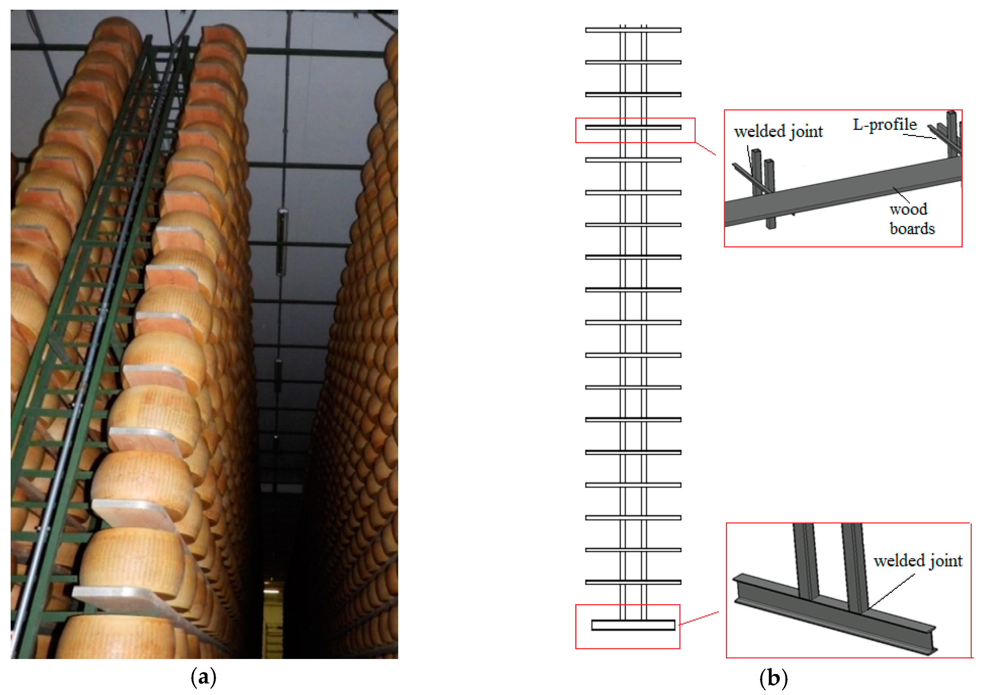
Figure 1). At that time, only a typology of cheese racks was used (
Figure 2). In particular, a set of built-up steel columns, each of them consisting in two hot-rolled tubular members (chords) welded to horizontal angles (battens), is connected via wood boards supporting cheese wheels for aging. In the longitudinal (down-aisle) direction, the built-up columns are equally spaced at approximately 1.5 m, allowing to store three wheels in each bay per side and vertical X-cross bracing are usually located at the external bays.
These old steel cheese racks, which substituted wood racks extensively used in the previous centuries, have been erected since the beginning of the last century basing on the blacksmith expertise, i.e., with very poor structural checks and neglecting all the aspects associated with safety against earthquakes. As a consequence, cheese racks that survived without relevant damages also to the recent earthquakes require now an accurate check by structural engineers to evaluate the effective degree of safety by considering both the progress in the state-of-knowledge as well as the improvements in standard design provisions. Frequently, the level of safety required by the modern design approaches cannot be guaranteed by these old cheese racks and hence additional bracing systems as well as suitable restraints to the walls of the warehouse can be required to improve remarkably the structural seismic efficiency.
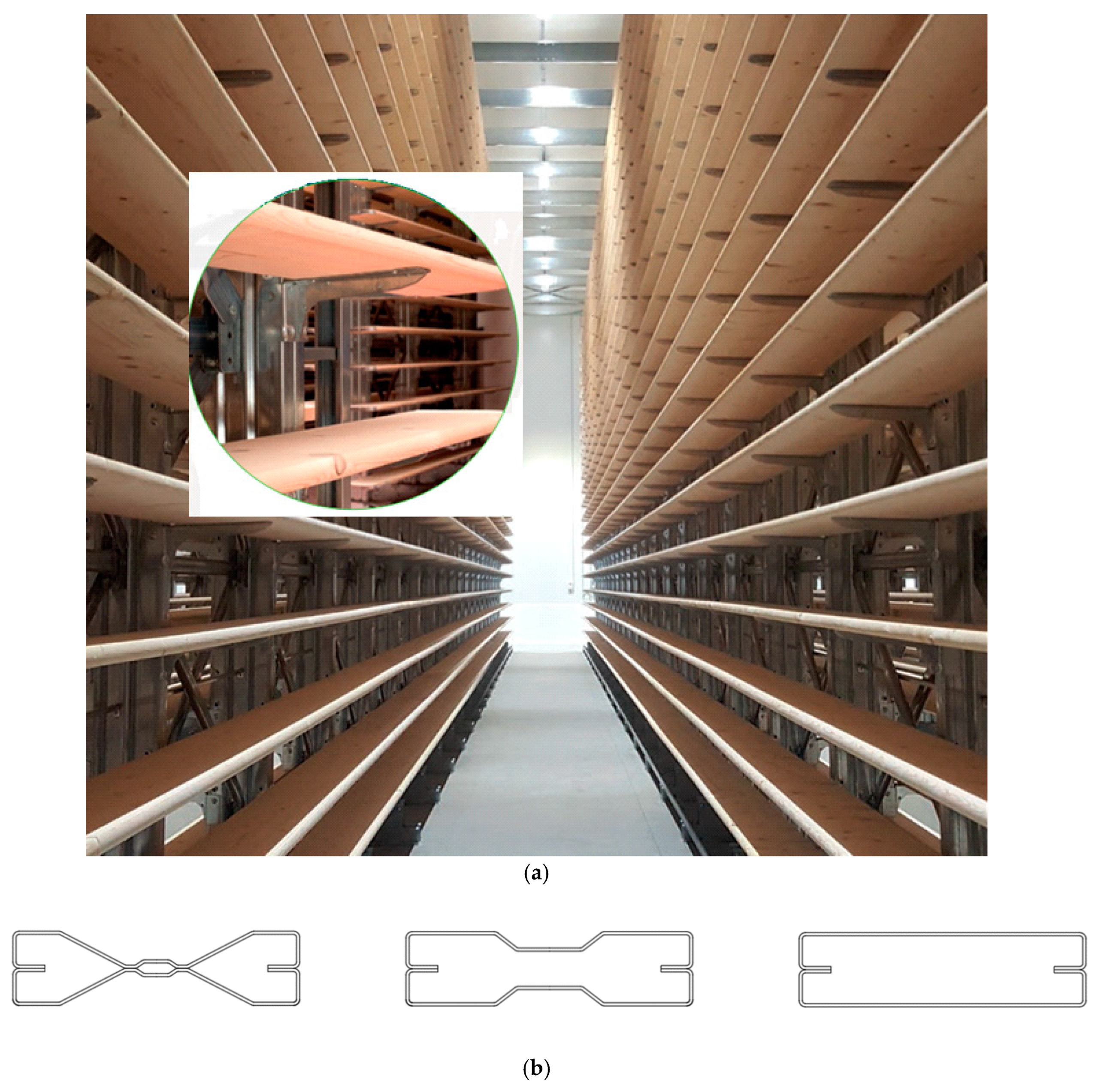
As an alternative, in many cases, it could be convenient to substitute completely the existing racks with the new types (
Figure 3a) now available on the market, that are realized by using cold formed steel members, like for the traditional storage pallet racks [
2]. Unlike for the old cheese racks, the connection with the cold-formed angles supporting wood boards as well as the bracing system components are realized by using structural bolts, instead of using hooks and slots, as in pallet rack practice. Boxed composite columns (different from producer to producer) are realized by coupling two open cold-formed mono-symmetric channels or sigma members (
Figure 3b). The thickness of the columns generally change from producer to producer and it is comprised between 2 and 3.5 mm. Along the columns height (in general about 7–9 m) horizontal L-profiles (angles) are connected, vertically spaced at about 330 mm and protrude beyond the central column as cantilever beams supporting the wood boards (with 30 mm thickness), on which cheese wheels are directly located. In the longitudinal (down-aisle) direction, the geometry of the oldest and new type cheese rack is the same, differing only for the structural components and for the connection system between columns: in the modern systems the columns are connected one another via horizontal hollow circular tubes every 3–5 line of wood boards, realizing together with the X-type bracings located in few panels, a partially braced frame. Furthermore, wood boards are continuous along 3 bays (4.5 m), as in the systems used in the past.
Steel cold-formed grana cheese racks have been developed about 10–15 years ago, but their extensive use was mainly after the 2012 Emilia Romagna earthquake. Unlike the old grana cheese racks, in the modern ones, base-plates are made by stiff elements connected to the columns and anchored to the floor via suitable mechanical fasteners and no lateral elements connect rack to the warehouse lateral walls.
Static and seismic behavior of the more traditional pallet racks, for both components and full-scale systems, has been quite deeply investigated [
3,
4,
5,
6,
7,
8,
9,
10] but limited heed has been paid to modern cheese racks, whose response is significantly different [
11], owing to the presence of a hybrid wood-steel structural systems and to the absence of beam-to-column connections. Moreover, despite it is well-known that reduction of seismic vulnerability of both pallet and cheese racks can be obtained by using base-isolation or passive control systems [
12], no evidence is up-to-now available on the applicability of the associated research outcomes to racks for Grana cheese.
In the past, cheese racks were considered as non-structural elements [
13,
14] but for approximately 15 years to now their seismic design must be carried out in according to the EN16681 [
15] provision, despite the fact these provisions have been developed specifically for the classical adjustable steel pallet racks. Four methods of analysis can be used, which are the same adopted for conventional buildings [
16,
17]:
Due to their high flexibility (generally the first period T1, on the down-aisle direction, is longer than 1.5 s) the LFM approach, it can hardly be applied to rack frames. Furthermore, the modal mass associated with the first fundamental vibration mode rarely reach the 90% of the total mass.
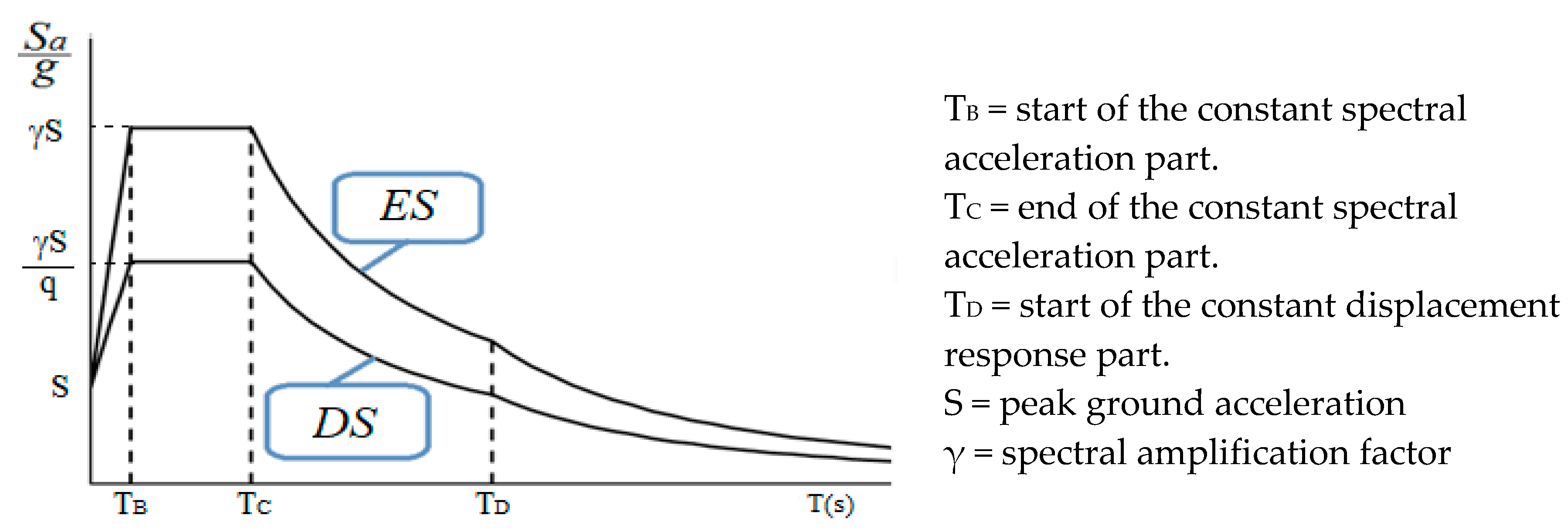
Due to these two conditions, the MRSA is the approach most frequently used in routine design. The results of both the LFM and the MRSA design strategies are depended on the behavior (q-) factor [
20]: q- factor is a predetermined value which permits to suitably scale the elastic response (
ES) spectrum obtaining the design response (
DS) spectrum. As an example, in
Figure 4 are reported both spectra in terms of
Sa/
g versus T, i.e., the acceleration (
Sa) normalized by the acceleration of gravity (
g) versus the period of the structure. The same
ES prescribed for conventional buildings is applied also to rack structures.
It is well-known that the q-factor estimation is a critical issue that impacts on the assessment of the seismic performance of the racks and still need further investigation. As already mentioned, Europeans rack provisions do not cover the cold formed cheese rack. For the more traditional pallet racks, a simple classification is proposed: for non-dissipative structures q < 2 and for dissipative ones q > 2. In the last years, the behavior factor of rack frames has been directly estimated from experimental and numerical pushover curves. More in detail, Kanyilmaz et al. [
21,
22] tested experimentally two-bay four-story unbraced and braced pallet racks: an inverse triangular lateral forces pattern has been applied to the specimens and increased till the collapse. The obtained experimental q-values range from 1.24 to 3.85. The plastic sources on the common typologies of steel storage racks are concentrated on the connections (base-plate and beam-to-column) as clearly demonstrated by recent researches [
23,
24]. On the contrary, on as far as cheese racks are concerned, in case of X-bracing with diagonals resisting only to tension, like the ones herein considered, the only elements that can ensure large excursions in the plastic range are the base-plates connections.
A study is currently in progress on cold-formed steel grana cheese racks, which started few months ago at Politecnico di Milano. It comprises of different phases: (i) experimental in-situ activities based on the modal identification techniques (currently in progress) adopted to characterize Italian cheese frame typologies differing mainly for the number of bays and for the load levels; (ii) deep study of the seismic and monotonic behavior of the tested structures, which is the core of the present paper; (iii) definition of reliable design rules accounting for key features of both the old and new grana cheese racks. The paper presents few remarks related to the design strategies which are currently adopted by considering a case history of interest for practical design purposes. Both the modal response spectrum analysis (MRSA) and the nonlinear time-history (NLTH) approaches are applied to appraise the performance making reference to two different earthquake conditions. Research outcomes stress the difference in terms of expected performance underlining the importance of an accurate definition of the behavior (q-) factor.
2. The Considered Cold-Formed Grana Cheese Rack
As previously mentioned, reference is herein made to a cold-formed grana cheese rack. The columns are composed by two sigma profiles whose webs are in contact in the central zone (
Figure 5). Only the ratio between the second moment of area (I
1/I
2) and the section moduli (W
1/W
2), along the principal cross-section axes have been reported. Due to confidentiality of the products, it is not possible to present additional data. As previous discussed, along the columns height cantilever members made by cold-formed L section are connected to the composite boxed column each 330 mm.
In
Figure 6, the details of the finite element (FE) model used for this study is reported, which have been developed for academic and research activities. To model the cheese rack, 18,770
beam elements with 6 degree of freedom (DOF) on each node have been used. The
beam formulation is based on the Timoshenko theory, i.e., shear deformation of the elements has been included. For both the longitudinal and the top bracings moment end releases have been included, to transmit only axial forces on these elements. The cantilever L-profiles (300 mm of length) are directly connected to one end to the columns while on the other end to the wood boards. In detail, the wood boards were modelled with the same six DOF
beam elements with the reference to the middle line position of the cheese wheels. Releases have not been inserted nor in the wood boards or in the cantilevers. To simplify the down-aisle view, wood boards are simply indicated with a short line in
Figure 6. Two different materials were modelled: steel S350 grade with Young modulus (E) equal to 210 GPa and Poisson ratio of 0.3; wood with E = 11.8 GPa and a Poisson ratio of 0.25. For the buckling analyses the well-known Jacobi procedure has been considered with a convergence tolerance of 1.5 × 10
−9. The storage levels are 20 in total (numbered from the bottom to the top) equally spaced. It can be noted that on the two external rows the half of the wheels are present while, each internal column supports 3 wheels per side on each storage level. Loads have been modelled as uniformly distributed on the wood boards. Only the fully loaded racks case has been considered because it represents the most interesting load condition. In fact, in this kind of structures, once the warehouse is filled, cheese wheels stay in the same position for a long time for aging. Consequently, the movement of goods is very limited, and it is rare to find different load conditions.
Nonlinear analyses have been carried out and all the members have been assumed to behave in elastic range, since they are classified as class 4 cross-sections, following the prescription of Eurocode 3 part 1-1, EC3-1-1 [
25]. The plasticity has been concentrated on the base connections, which have been modeled as rotational springs. The moment-rotation (
M-Φ) law, comprised of both the linear part and the softening branch, is presented in
Figure 7: a different response has been considered depending on the axial load level, according to experimental studies on the column bases of racks [
26], which is different for external and internal columns. The resistance (
MJ,Rd) and elastic stiffness (
SJ) of the connections has been related to the flexural strength (
Mc,Rd) and stiffness of the column, respectively. In particular, the flexural stiffness of the column is proposed according to EC3-1-8 [
27] classification criteria, i.e.,:
where
E is the Young’s modulus,
Lc and
Ic are the length and the second moment of area, respectively, of the pallet column and
β is a reduction factor, which depends on the axial force value acting on the joint. The kinematic model has been assumed to simulate the hysteresis behavior.
In the following, the values of
β = 0.15 and
β = 0.08 have been adopted for internal and external bases, respectively, owing to the connection details associated with the considered cheese rack. It can be noted that
β = 1 corresponds to the limit between semi-rigid and rigid bases, which is a condition rarely achieved, being the bases very flexible in pallet as well as in cheese racks. Verification checks have been carried out by means of the general method (GEM) [
2,
25]. Attention should be pay to the safety index (
SI), which is a coefficient that offers the grade of utilization of the structural components ranging from 0 to 1. The structural safety is achieved when:
where
αult,k is the minimum load multiplier based on the components resistance,
γM is the material safety coefficient and
χop is the overall buckling reduction factor which depends on the global critical buckling multiplier of the structures (
αcr).
In particular,
αult,k is evaluated as:
where
My,Ed, Mz,Ed and
NEd are the bending moments along the principal axes and the axial force acting on the members and
γM0 is a safety coefficient, generally equal to 1.0 or 1.05. Furthermore,
Aeff is the resistance of the member in compression considering the effective area and
Weff,y and
Weff,z are the resistance of the member subjected to bending along the principal axes.
Likewise, other approaches of the GEM method can be adopted for structural verification checks both for monotonic and seismic design cases. According to the European code and considering the rules for the load combination, it has to be highlighted that:
The static performance must be always checked considering the ultimate limit state (ULS). A factor of 1.3 (γG = 1.3), amplify the weight of the rack components (G) while 1.4 (γQ = 1.4) is prescribed for the weight of the pallet units (Q). The associated SI evaluate with this combination on the main stressed column is herein named ;
As to the seismic combination, there is no need to amplify the weight of the of the rack components and of pallets units, i.e., γE = γG = γQ = 1. The associated SI evaluated with this combination on the main stressed members is in the following identified as SISLV.
As to the base-joint, only the resistance should be checked, according to the equation:
where
MJ,Ed is the bending moment acting on the base-joint and
MJ,Rd is the joint resistance.
3. Static Performance
As required by the GEM, the elastic critical buckling multipliers (αcr) of the overall structure has been evaluated, by considering the ULS load combination. The weight of cheese wheels, i.e., Q, has been assumed equal to 43 kg while the self-weight is automatically calculated by assuming a unit weight of the steel and of wood boards equal to 78.6 kN/m3 and 5.0 kN/m3, respectively. Considering one internal row, the self-weight of the sole steel-wood structure is about 9.0 ton (3.4 ton and 5.6 ton for steel and wood, respectively), while the total load of the cheese wheels is equal to 103 ton: the live-to-dead load ratio is equal to 13.
In
Figure 8, the buckling mode is depicted together with the associated multiplier (
αcr,ULS). As it can be noted, the buckling shape is associated with an overall flexural mode in the down-aisle direction. Since
αcr,ULS < 10, second order effects must be always considered in both static and seismic analyses. If
Figure 8 is considered, it can be noted that the braced panels at the lowest levels (1st to 6th) are not involved in the buckling deformed shape forming a quite rigid zone. The buckling shape starts from the 6th storage level. The presence of cheese wheels influences the buckling with only their weight do not giving any additional restraint.
After the buckling analysis, second order analysis have been executed to evaluate the internal forces distribution and calculate the safety factor on each member and base joint. The values of the maximum safety index are reported in
Table 1.
It is worth noting that, since in the monotonic load combination the only lateral forces are the structural imperfections, the bending moment acting on the base connections is quite negligible with respect to their resistance, as confirmed by the very low value of the associated SI.
4. Seismic Performance
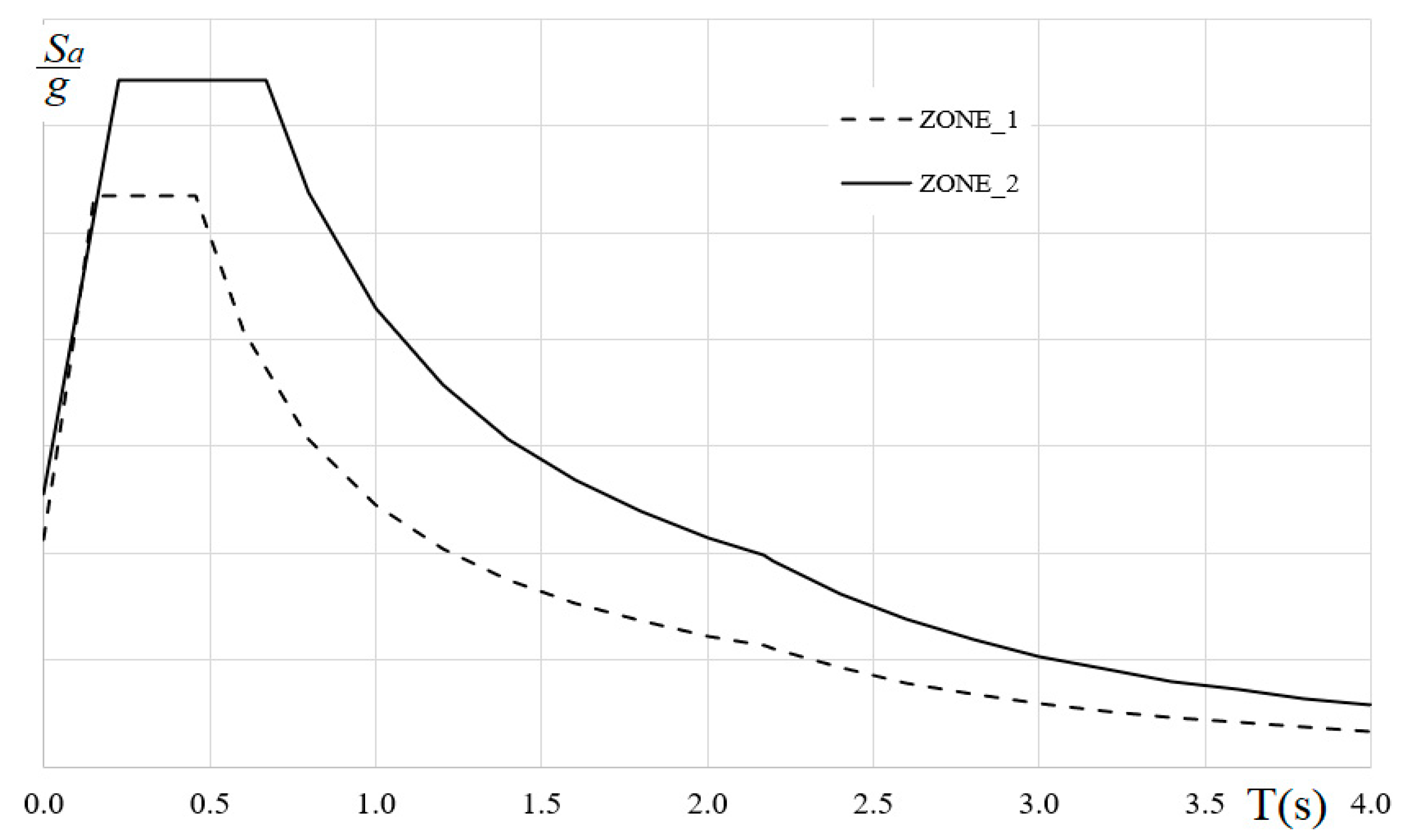
As far as the seismic input is concerned, two different zones in the center of Italy have been chosen in which Grana warehouses are effectively located. They could be easily identified with their coordinate: Zone_1 (latitude and longitude are 44.27° and 10.94°) and Zone_2 (latitude and longitude are 44.49° and 10.34°). Furthermore, soil categories were B and C for Zone_1 and Zone_2, respectively. In accordance with the Italian code for structural building design [
28], the associated elastic spectra (
Figure 9) have been defined and, for each of them, four different spectra have been obtained by using a scale factor
αg. In order to define a set of cases of adequate interest for practical design purposes, the
αg values of 0.1 (reduction to 90%), 0.3, 0.5 and 1 (no reduction) have been considered.
In total, eight different design spectra have been considered and for each of them, ten synthetic spectrum-compatible earthquakes (total duration 30 s) have been created with the program SIMQKE (SIMulation of earthQuaKE ground motions) [
29] and then used as input for the NLTH analyses. The earthquakes were considered acting along the cross- or the down-aisle direction.
Moreover, for the MRSA behavior factor values ranging from 1 to 3 have been considered, with a step of 0.5. It should be highlighted that:
4.1. Modal Response Spectrum Analyses
As it is well-known, the MRSA is based on the modal (eigenvalue) analysis and hence the response is governed by the elastic part of the
M-Φ joint curve. Each natural mode of vibration, that is directly associated to an acceleration value,
Sa(T), provide its contribution on the final results. As an example,
Figure 10 can be considered where the first two modes (in terms of eigenvalues and modal shapes) have been plotted together with the associated accelerations. The importance of each mode depends strictly on the involved mass and the total number of modes to be included must be sufficient to reach 80% of the total mass on each principal direction. Among the different rules that can be used to combine the results associated to each mode, the complete quadratic combination rule (CQC) has been herein adopted. As previously discussed, the results obtained by this method are strictly depend on the chosen q-factor.
Displacements and forces obtained from the MRSA are then combined in absolute value (subscripts MRSA) to the one of the static analysis (subscripts STAT) obtained with
γG =
γQ = 1:
As far as the MRSA outcomes are concerned, the maximum
SI evaluated in members and base- plates are in
Table 2 by considering the output analysis results both in the cross- and down-aisle directions. Due to the different safety factors applied in ULS and seismic combinations, for low acceleration levels, the resulting internal forces raised from the MRSA could be less severe than the ones associate to the monotonic case: in these cases, the load carrying capacity is governed by the monotonic case (and are indicated with a grey background in the table). Moreover, values greater than unity are reported in bold.
As expected, by increasing the q-value, the internal forces acting on the cheese rack decrease with a reduction of the safety index. Moreover, the reduction of the is not proportional to the increase of the q-value. Furthermore, it can be remarked that:
Maximum values of the bending moments, considering earthquake effects, are located at the base-plate and between the 6th and the 10th storage level, due to the presence of the braced panel between levels 1st and 6th which generates a localized rigid zones (
Figure 8);
As expected, in several cases the values are lower than the because of the presence of lower axial forces on the columns and quite negligible values of the bending moments;
If the ratios between the obtained with q = 1 and the one obtained with q = 3 are compared, it appears that the influence of the q value is greater for strong earthquakes, ranging from 1.35 up to 2.51, in case of αg =0.1 and for αg = 1.0, respectively, confirming the importance of the accurate definition of q-factor on the safety of cheese rack;
If Zone_1 is considered, the SI of the members is always lower than unity while for the worst scenario (q = 1 and αg = 1) the joint resistance is not satisfied >1. For this case the structure is not verified;
If Zone_2 is considered for the worst case (q = 1 and αg = 1), structural checks are not satisfied in both members and connections.
Since the SI can be related to the safety level of the structures, also a little variation of this value can make a difference between a safe and an unsafe structural design.
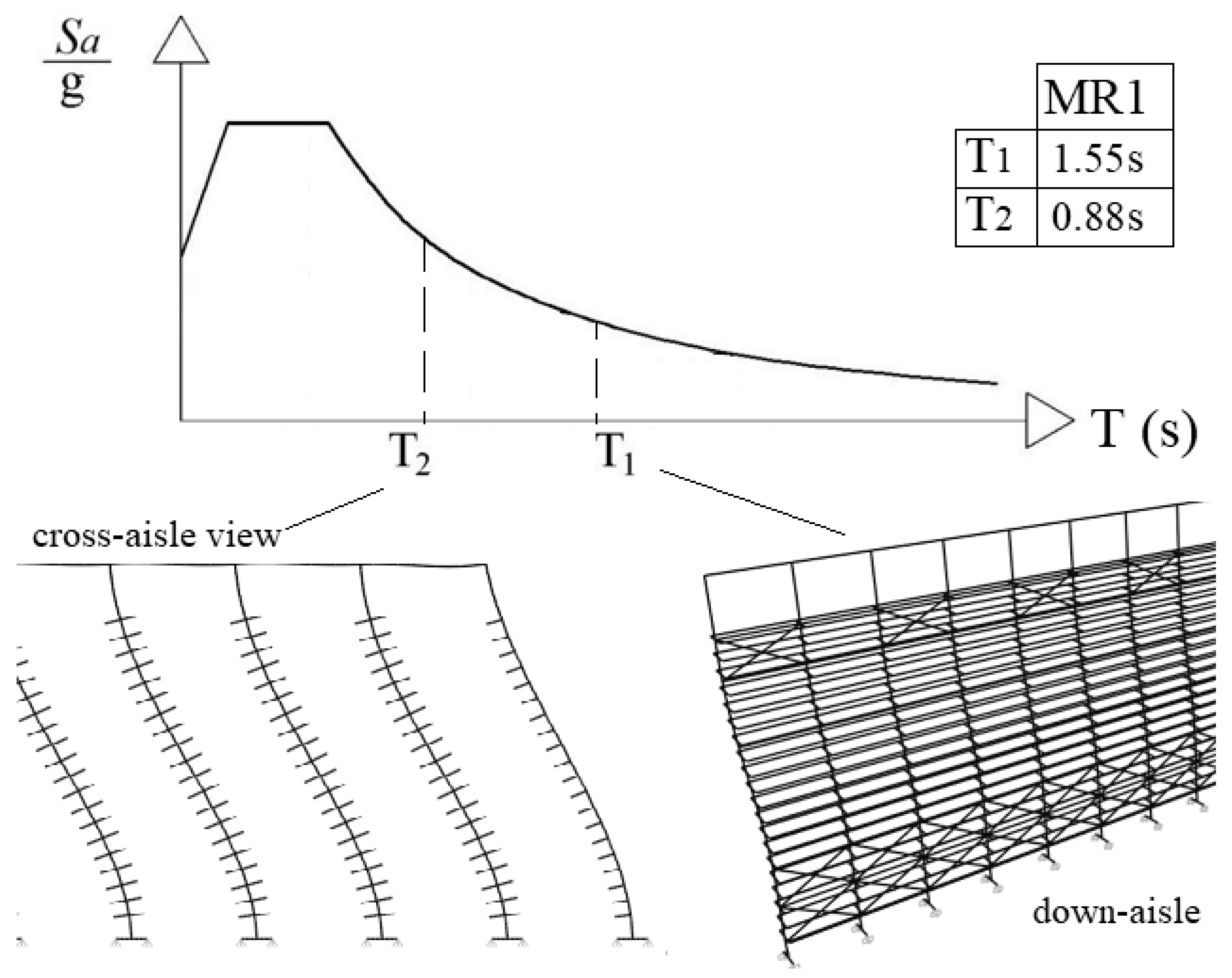
Finally, a check on the maximum displacements and maximum interstory drifts is necessary to verify the seismic behavior of the frame. Since the fundamental period of the frame is greater than T
C (
Figure 4), the deformations must always be checked with q = 1, also when a q > 1 has been assumed in design [
28]. In
Table 3, the maximum displacements associated with the worst load combination, on the cross- and down-aisle directions have been reported for both the zones. For the sake of brevity, only the displacements associated to five different storage levels have been reported.
Displacements increase linearly with the increase of αg and the deformed shape in the down-aisle direction is a cantilever type with the displacement increasing with the increase of the height. As showed also by the modal and buckling analyses, the braced panel at the first levels is subjected to very small deformations. In the cross-aisle direction, the maximum displacements are not located on the last storage level, since the connections between the rows on the top and the presence of the floor bracings system, create an additional rigid zone. Otherwise, the longitudinal X-bracings on the bottom does not affect the cross-aisle displacements.
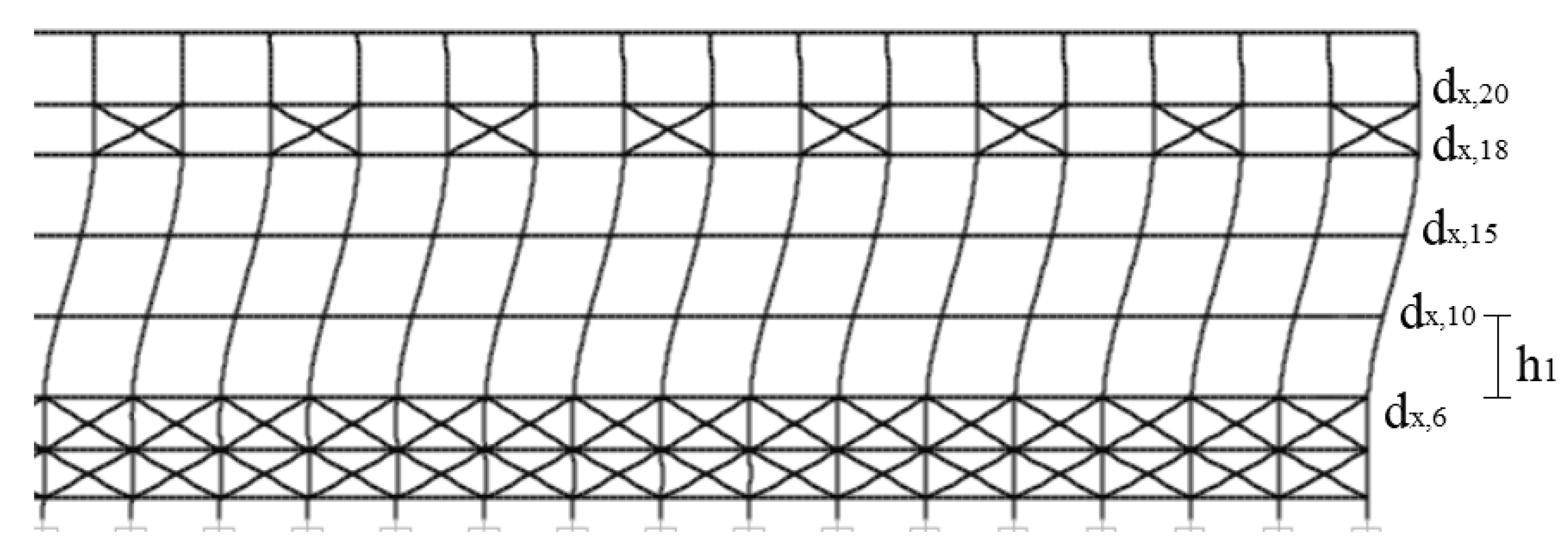
The maximum displacement value reached on the longitudinal direction is quite high: about 1/70 and 1/35 of the total height for Zone_1 and Zone_2, respectively. To evaluate the interstory drifts in the down-aisle direction, reference has been made only to the drift between panels, as showed in
Figure 11 the interstory drift ratio
has been evaluated, referring to q = 1, as the ratio between the interstory drift between panels over the panel height:
where
dx,i and
dx,i-1 are the absolute horizontal displacements at the considered and at the previous
i-th panel level and
hi is the panel height. The interstory drift ratio evaluated via Equation (6) can be assumed as the maximum interstory drift ratio occurred during the earthquake.
The associated results are reported in
Table 4, for all the considered α
g in terms of interstory drift ratio. It is worth noting that the limit given by EC8 is 1% for the serviceability limit state in case of buildings without non-structural elements.
The bracing system used in cold-formed cheese racks, which is completely different from the one typically adopted in pallet racks, could bring to the creation of an unsafe local collapse mechanism with the formation of a weak point in correspondence of the 6th storage level.
4.2. Nonlinear Time-History Approach
Nonlinear time-history (NLTH) analyses have been performed on the rack. Second order effects have been directly accounted for by the FE beam formulation and the material non-linearity has been considered by assuming an elastic-plastic constitutive law with kinematic hardening concentrated only at the bases. For the second order effects geometrical stiffness matrix has been directly included in the software considering the influence of the axial load acting on the elements.
In the analyses a structural damping of 5% has been assumed. Moreover, the damping matrix is considered proportional to both the mass and the elastic stiffness matrices. As to the input is concerned, 10 spectra compatible accelerograms with 30 s of duration have been considered with a step Δ
t = 0.005 for a total of 6000 steps, according to the European seismic code [
16]. The direction integration method by using the well-known Theta-Wilson procedure has been applied by considering a coefficient of integration equal to 1.4 (iteration convergence tolerance equal to 1.0 × 10
−4). All the nonlinear time-history analyses started after the static ones in order to consider the effects of the axial loads and to form the geometrical stiffness matrix.
The NLTH procedure appears, in the author’s opinion, the only procedure allowing for an exact evaluation of the effective safety of the cheese rack step by step during the earthquake. Moreover, is the only procedure that permits also to appraise the post-seismic health condition of the frame [
31]. Typical output data associated with this design strategy are:
Fully hysteretic behavior dissipative components. In particular, by calibrating experimentally a suitable moment-rotation law, it is possible to define the cyclic post-elastic behavior and evaluate accurately low-cycle fatigue damage components;
Displacements or accelerations vs. time on each nodal point of the frame. As it is well-known in rack structures, high level of accelerations could bring to the topple of the wheels [
32,
33] and for this reason it is of paramount importance to check their entity;
Check of the resistance and stability of members during the earthquake. Since it is possible to stress out the internal forces step-by-step during earthquakes, the SI of interest can be directly evaluated;
Eventual failure condition for cheese racks by accounting for the interaction between plasticity and instability.
Despite the great number of information associated with this design approach, it is rarely used in routine design because of the complexity and the great amount of output data requiring automatic procedures, which are not yet available, to process them.
In
Table 5 the results in term of maximum
reached on structural members have been reported. In detail, the mean value, the maximum (max), the minimum (min) and the 95% fractile (Fract) observed for the set of the ten considered earthquakes, have been showed. The cases for which the ULS is more severe than the seismic
SI have been highlighted with a gray background while values greater than unity are in bold.
By considering the mean values, it can be concluded that the cheese rack is always from the safe side for both Zones (< 1), for both earthquakes: the min and max values are from 10% to 30% different than the mean ones, owing to the different frequencies content of the generated spectra-compatible accelerograms. Furthermore, it can be highlighted that:
If the maximum values are considered for both Zone_1 and Zone_2, the is greater than one only when αg = 1.0, confirming the validity of the selected structural system. In these cases, convergence of the analyses is always achieved. Failure due to interaction between plasticity and instability is not observed, and SI values greater than unity are associated with local plastic hinges, increasing the deformability of the cheese rack;
It is confirmed that maximum are located at the bases and between the 6th and the 10th storage level, confirming that the bending moment distribution obtained via the NLTH is compatible with the one obtained via the MRSA analysis;
As expected, for αg = 1.0, the base-plate connections dissipate energy through their hysteretic behavior.
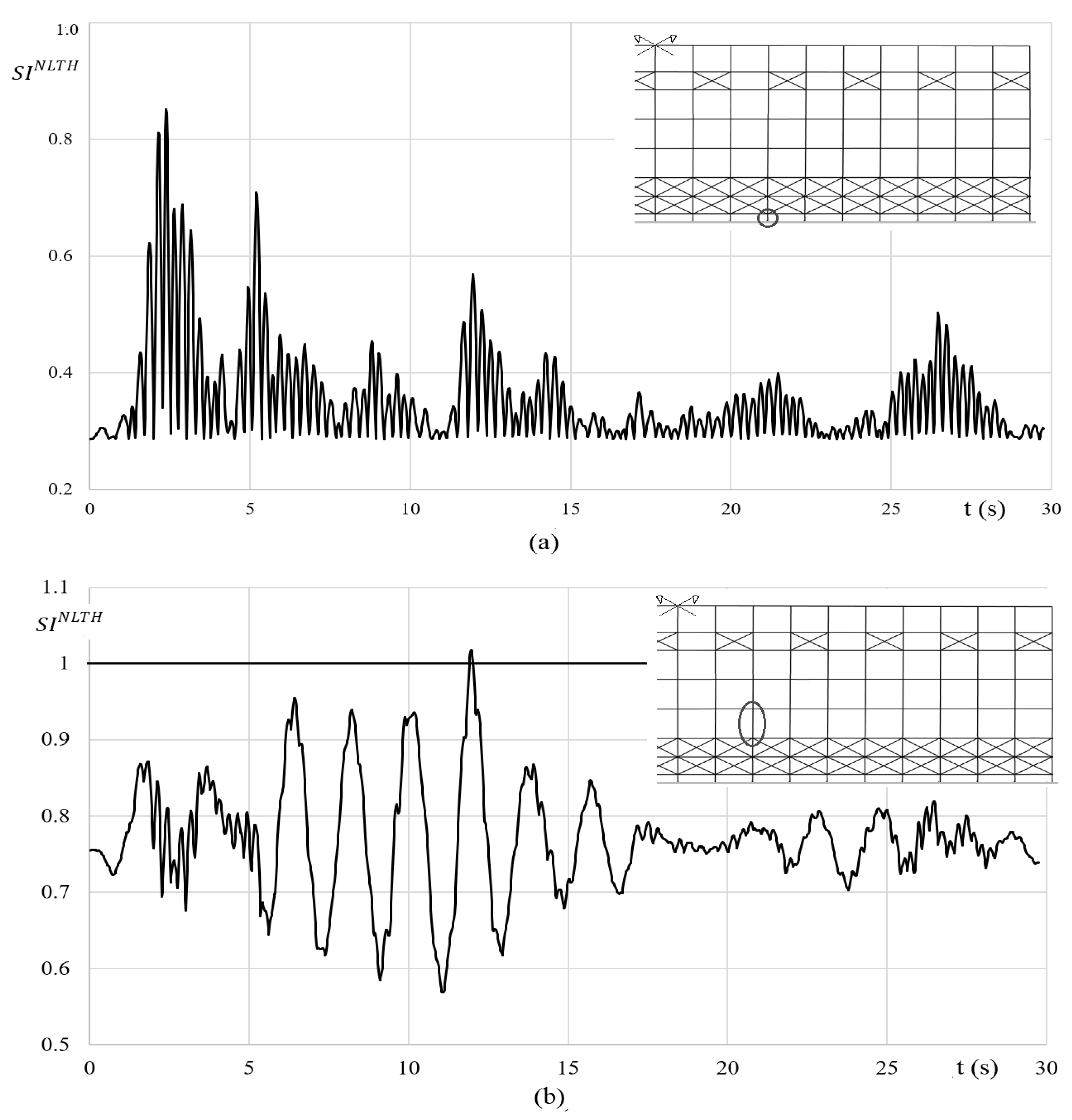
As an example of the re-elaboration of the output results, the distribution of
for one accelerogram generated from Zone_2 with
αg = 1.0, can be considered (
Figure 12), which is related to two different internal columns in the central zone of the cheese rack.
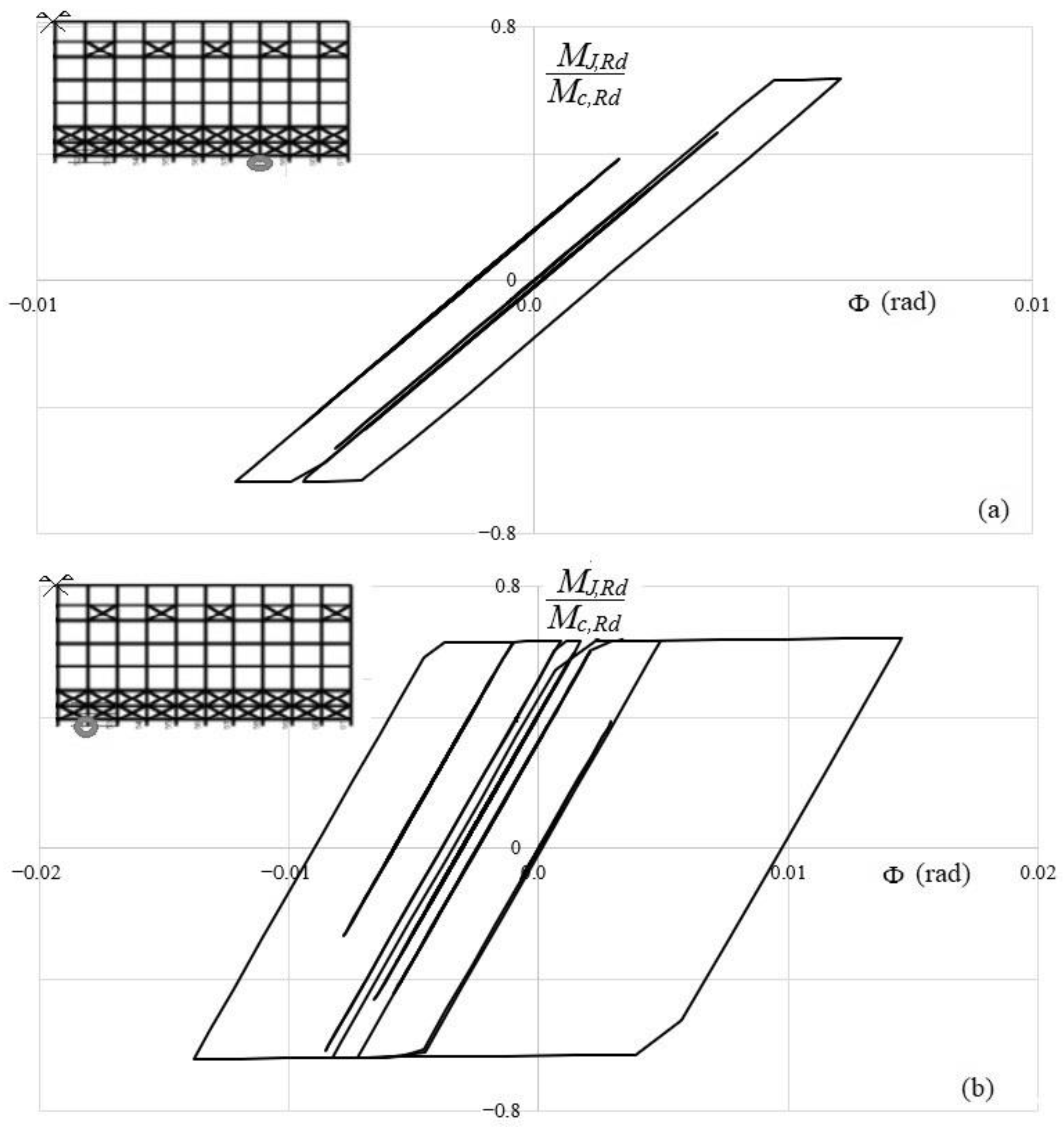
Regarding the behavior of base-plate connections, in
Figure 13, an example of the hysteretic cycles has been reported for Zone_2 with
αg = 1.0. In particular, a base near to the center of the row and one near to the end has been depicted.
With the considered hysteretic rule the cycles appear stable and the energy dissipation is relevant.
In
Table 6 and
Table 7 the mean displacements along the cross-aisle direction for the 15th level and the ones in the down-aisle direction associated to the last storage level (level 20), have been reported, respectively.
The variability of the displacements does not linearly depend on factor αg, due to the influence of both mechanical and geometrical nonlinearities in the frame components. The maximum down-aisle displacements at the last level are non-negligible for αg = 1.0, about 1/30 of the total height of the frame, confirming, once again, the quite great flexibility of the system.
Finally, in
Table 8, the mean values of the maximum interstory drift ratio along the down-aisle direction are reported, evaluated in accordance with Equation (6). Only the worst scale factor has been considered (i.e.,
αg = 1.0).
It is worth noting that these values are in many cases, extremely high, confirming the importance of checks associated with deformability in addition with the ones related to stability and resistance checks.
6. Concluding Remarks
After the 2012 Emilia Romagna earthquake, cheese racks showed their inadequacy to resist to lateral loads: a great number of these structures collapsed producing non-negligible economic damages. For this reason, thanks to the great expertise of the steel storage rack producers, cold-formed cheese racks have been developed and proposed on the market.
These new storage systems for cheese wheels, formed by cold-formed members and bolted connections, have not been accurately studied up to now and are not addressed in specific standard provisions. Their static and seismic design is carried out by considering the set of standards usually adopted for the traditional adjustable pallet racks [
15]. These frames are characterized by a great flexibility, since in the longitudinal direction columns are connected only via horizontal hollow circular tubes every 4–5 line of wood boards, forming the so-called panels, and the X-bracings are present only in a few of them. Therefore, the overall stability as well as the structural behavior of cheese frames is remarkably influenced by the rigidity, resistance and hysteric behavior of the base-plate connections.
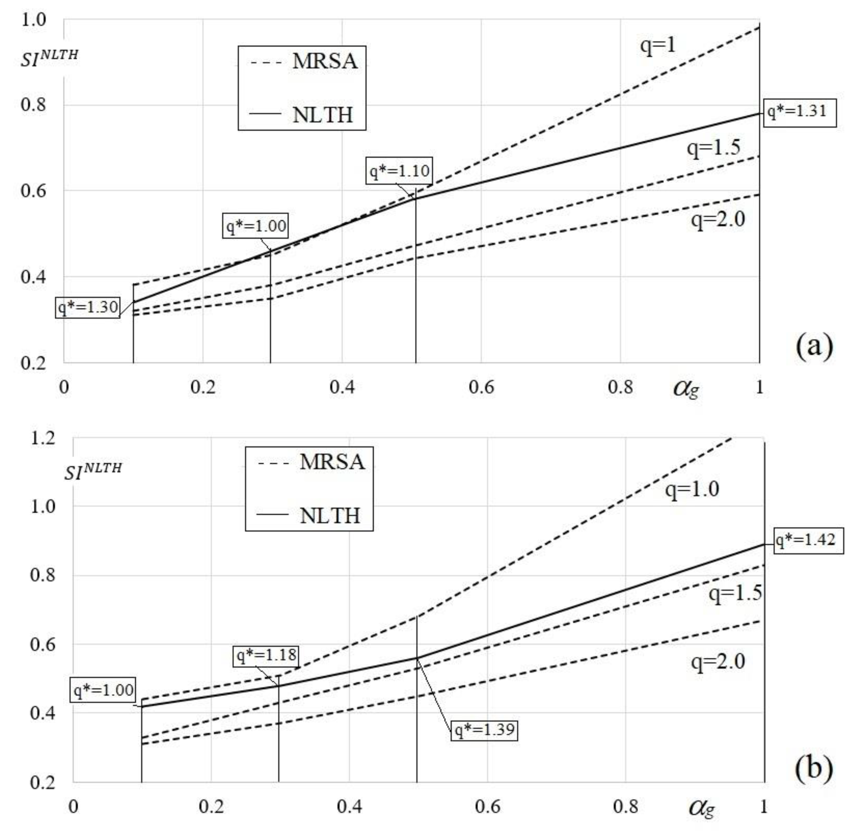
In the paper, the preliminary results on a study on cheese racks are presented and both MRSA and NLTH design approaches have been applied to a cheese rack configuration of interest for practical design purposes. After a short discussion on the peculiarities of both the considered approaches, making reference to two different seismic zones, attention has been addressed to the accurate evaluation of the q-factor. In particular, by comparing the performance obtained via the NLTH with the one obtained via the MRSA an equivalent q* has been defined. The value q* can be intended as the effective behavior factor of the cheese rack. It has been shown that the q* generally results lower than 1.5, stressing out the inadequacy of the procedure currently adopted in routine design, which allow values of q- up to 2.0 and confirming the needs of further accurate and extensive investigation on these frames. Finally, since cold-formed cheese racks seem prone to the formation of local collapse mechanism [
34], it could be interesting, as future research, to study robustness [
35] and in particular, the effect of the longitudinal bracings on the progressive collapse, i.e., on the domino effect.


