Evaluating Timoshenko Method for Analyzing CLT under Out-of-Plane Loading


School of Engineering, Deakin University, Waurn Ponds, VIC 3216, Australia
*
Author to whom correspondence should be addressed.
Buildings 2020, 10(10), 184; https://doi.org/10.3390/buildings10100184
Submission received: 31 August 2020
/
Revised: 7 October 2020
/
Accepted: 12 October 2020
/
Published: 14 October 2020
(This article belongs to the Section Building Energy, Physics, Environment, and Systems)
Abstract
:Cross-laminated timber (CLT) is an engineered wood product made up of layers of structurally graded timber, where subsequent layers are oriented orthogonally to each other. In CLT, the layers oriented in transverse direction, generally termed as cross-layer, are subjected to shear in radial–tangential plane, which is commonly known as rolling shear. As the shear modulus of cross-layers is significantly lower than that in other planes, CLT exhibits higher shear deformation under out-of-plane loading in contrast to other engineered wood products such as laminated veneer lumber (LVL) and glue laminated timber (GLT). Several analytical methods such as Timoshenko, modified gamma and shear analogy methods were proposed to account for this excessive shear deformation in CLT. This paper focuses on the effectiveness of Timoshenko method in hybrid CLT, in which hardwood cross-layers are used due to their higher rolling shear modulus. A comprehensive numerical study was conducted and obtained results were carefully analyzed for a range of hybrid combinations. It was observed that Timoshenko method could not accurately predict the shear response of CLTs with hardwood cross layers. Comprehensive parametric analysis was conducted to generate reliable numerical results, which were subsequently used to propose modified design equations for hybrid CLTs.
1. Introduction
Structural timber products can be classified into structurally graded timber boards and engineered wood products. Products such as laminated lumber veneer (LVL), glue laminated timber (GLT), and plywood have been used for decades [1]. Cross-laminated timber (CLT), on the other hand, is relatively new to the construction industry. The concept of CLT was originated in Austria in the early 1980s. Unlike GLT in CLT subsequent lamina are orthogonal to each other along thickness direction. Most cross-laminated timber is made up of 3 to 5 layers although 7 and 9 layered CLTs are also used in construction [2]. Due to its orthogonal make up, CLT can sustain bi-directional bending in contrast to other structural timber products which typically carry the load in one direction [3,4]. The makeup of CLT could be either homogeneous or heterogeneous. In homogeneous CLT, timber boards used in longitudinal layers and cross-layers are of same structural grades, whereas in heterogeneous CLT, the cross-layers are made of timber with inferior mechanical properties [5].
CLT offers relatively lower bending stiffness when compared to an equivalent GLT section. This can be attributed to the orthogonal layout of cross-layers and the lower rolling shear modulus in timber [6]. Timber boards are orthotropic in nature, where the mechanical properties vary along the longitudinal, tangential, and radial direction [7]. To improve performance of CLT under out-of-plane bending, some researchers investigated the use of engineered wood product such as laminated strand lumber (LSL) and laminated veneer lumber (LVL), as cross-layers [8,9].
Conventional CLT panels are manufactured from structural timber boards. Structural timber boards may be broadly classified into softwood and hardwood. Softwoods are timber sourced from conifer trees, whereas hardwoods are sourced from deciduous trees. The structural grades of hardwoods are generally higher than softwoods due to their superior mechanical properties. In addition, deciduous trees grow relatively slower making hardwoods more expensive [10]. Recent research has shown that the rolling shear modulus of hardwoods are significantly higher than that of softwoods [11,12], and this prompted research to investigate the prospect of using relatively lower quality hardwoods in CLT manufacturing so that higher rolling shear modulus can be achieved in cross layers without a higher price tag.
A number of analytical methods such as Shear analogy, Timoshenko, modified gamma, and k-methods are currently used to evaluate the performance of CLT under out-of-plane loading. K-method does not consider shear deformation and therefore is only applicable where shear deflection is insignificant i.e., in cases where the span-to-depth ratio of CLT is over 30 [13]. In modified gamma method, the cross-layer is considered to be semi-rigidly connected between two longitudinal layers [14], and the shear deformation of cross-layer is accounted for by using a slip factor, which is a function of the rolling shear modulus as outlined in mechanically jointed beam theory of Annex B of Eurocode 5 [15]. The effect of low rolling shear modulus of cross-layer with respect to the span-to-depth ratio was extensively investigated within elastic range using Gamma and Shear analogy method and it was concluded that shear analogy method estimates higher deflection due to shear deformation of cross-layer when compared against modified gamma method [16].
Shear analogy and Timoshenko methods are considered to be relatively more accurate for determining deflection in CLT [3]. The shear analogy method is relatively complex, in which CLT is reduced to two virtual beams that are coupled together by rigid web members. Bending stiffness of one beam is considered to be the sum of inherent flexural stiffness of each layer, whilst the bending stiffness of the other beam is given the “Steiner” points stiffness due to increased moment of inertia resulting due to their relative distance from the neutral axis [17]. Timoshenko beam theory is the extension of Bernoulli–Euler beam theory to account for the shear deformation of thick beams. Shickhofer [18] proposed a method based on the Timoshenko beam theory for evaluating out-of-plane behavior of CLT panels which has been referred to as Timoshenko method in the current study.
In this study, experimentally verified numerical models are used to examine the performance of Timoshenko method in predicting the deflection of CLT panels covering wide range of geometric properties and varying rolling shear modulus. The deviation of results between Timoshenko method and Finite element models were analyzed to determine the parameters that affect the variation in results.
Timoshenko method was also used to determine the deflection of simply supported hybrid CLT panels subjected to uniformly distributed load. Deflection values predicted using the analytical method was compared against numerically obtained results for CLT panels. Comparisons clearly demonstrated shortcomings of the current analytical model. A modification co-efficient for the Timoshenko method has been proposed to account for the effect of higher rolling shear modulus in hybrid CLT. Based on the parametric analysis, the proposed modification co-efficient was identified as a function of span, depth and rolling shear modulus of CLT panels. The proposed technique has been validated against available bending tests on relevant CLT panels.
2. Analytical Models for Deflection Calculation in CLT Panels
Timoshenko method was used in the current study to predict deflection including influence of shear deformation in CLT panels when subjected to out-of-plane loading. Following subsections present brief discussions on the analytical method so that readers can connect to results analysis sections.
2.1. Timoshenko Method
Timoshenko beam theory is an extension of Bernoulli–Euler beam theory to account for shear deformation in thick composite beams. Geometric properties of a typical three-layered CLT is illustrated in Figure 1.
Unlike Euler–Bernoulli theory, the cross-section is not assumed to remain straight and perpendicular to the neutral axis in Timoshenko theory which uses a shear form factor k to correct shear stiffness of the cross-section. The bending and shear stiffness of laminated beams are calculated using Equations (1) and (2), respectively [19,20].
where Ai = bhi.
where Ei and Gi are the elastic modulus and the shear modulus in MPa of the i-th layer. bi, hi, zi and a are width of the panel, height of the i-th layer, distance of the neutral axis of the i-th layer from the neutral axis of the panel in mm, and the distance between the neutral axis of the outer layers, respectively. Shear form factor, k is determined by using Equation (3) [21].
S (z) = First moment of area (mm3).
Deflection of the simply supported panel under uniformly distributed loading (UDL) condition can be determined using Equation (4).
where q is the uniformly distributed loading in N/mm and L is the span length of the panel in mm [22].
2.2. Shear Form Factor
As mentioned before, Timoshenko beam theory is an extension of Euler–Bernoulli theory, where the deflection due to shear deformation is also considered for calculation of total deflection. The kinematics assumptions used by Timoshenko beam theory results in presence of constant shear deformation through thickness of the section under out-of-plane bending. To compensate for the excess resulting shear deformation against results obtained from elasticity solutions, shear form factor has been introduced by Timoshenko. A range of shear form factor values has been proposed literature. The shear form factor suggested by Timoshenko originally was 3/2 for isotropic homogeneous solid section [23]. The most commonly used shear form factor value is 6/5 proposed by Reissner [23] based on First order shear deformation theory (FSDT). Shear form factor value of 12/π2 was proposed by Mindlin [24] and shear form factor was proposed to be a function of Poisson’s ratio by Cowper [25].
The estimation of shear form factor was extended for laminated composite beams by Barbero et al. [26], where he proposed a mechanics for thin-walled laminated beams. A theoretical approach was proposed by Davalos et al. [27] to evaluate the shear form factor for thick composite laminate with arbitrary lay-up configurations of layers. The evaluation of shear form factor in accordance to Equation (3) was proposed by Augustine et al. [28].
3. Finite Element Modelling
Three dimensional models of CLT panels with varying span-to-depth ratio and rolling shear modulus for the cross-layer were developed using commercial FE (Finite Element) package Abaqus 2016. All CLT panels were subjected to uniformly distributed loading and resulting deflections were captured from FE models to evaluate the performance of the considered analytical technique, i.e., Timoshenko method in predicting those deflections.
3.1. Material Model
CLT is a composite material and exhibits linear elastic behavior until some form of mechanical failure takes place. In practice, non-linearity in structural response is typically initiated due to either tensile failure in the bottom layer or rolling shear failure in the cross-layer. This study intends to investigate deflection behavior of CLT panels within linear elastic range, and hence linear elastic material model was used.
Timber is an orthotropic material, whose elastic behavior is different in three orthogonal directions [29]. The three orthogonal directions in timber are longitudinal, tangential, and radial direction, as illustrated in Figure 2.
Nine independent elastic constants are required to determine the mechanical response of orthotropic materials. These constants are three elastic moduli, three Poisson’s ratios, and three shear moduli. Orthotropic material property for timber can be reduced to transversely isotropic material by considering the radial–tangential plane to be isotropic, as the material properties are reported to be of the same order [30]. This assumption means that elastic moduli (ER and ET) and Poisson’s ratio ( and ) normal to each other in the radial–tangential plane becomes equal. Further, the shear moduli in the other two perpendicular planes become equal. The additional constraint can be expressed as
where L, R, and T represent longitudinal, tangential, and radial material direction, respectively.
Due to the constraint imposed by Equation (5), two independent Poisson’s ratios are reduced to one as two elastic modulus values are equal, resulting in reduction of nine-independent constants to 5. The consequent constitutive relationship is shown in Equation (6).
where R plane is considered to be isotropic and subscripts T are replaced by subscript R.
Elastic constants for timber material with reference to Figure 2b and Figure 3 are listed in Table 1.
The shear modulus in radial–tangential plane (GRT), commonly referred to as the rolling shear modulus, is dependent on the Poisson’s ratio and the modulus of elasticity of that plane. It is worth noting, that determining rolling shear modulus using physical tests is easier than determining Poisson’s ratio.
3.2. Geometry and Boundary Conditions
FE models were developed using fully integrated solid elements (C3D20) available in Abaqus 2016. Cubic elements of 8 mm were chosen based on conducted mesh convergence study. The width of all the models were kept constant at 200 mm. Span and thickness of the developed models were varied to investigate their effects on the behavior of panels under out-of-plane loading. The models were subjected to uniformly distributed load for simply supported boundary condition. Figure 3 shows the model geometry and applied loading.
The parametric study consisted of 52 models of varying combination of span and thickness. Span lengths of the CLT panels were varied between 2 and 5 m considering current design practice for engineering wood products. Span lengths were changed by 250 mm increment between 2 and 5 m. Three-layered CLT panels with total thickness of 90, 120, 150, and 180 mm were used for each span length. These variations produced a wide range of L/D ratio ranging between 11.11 and 58.33. The uniform loading was considered constant at 1.5 N/mm so that the maximum deflection was not excessive.
3.3. Material Properties
Mechanical properties used for longitudinal layers both in FE models and in analytical calculations were mostly taken from standard values recommended for C24 grade structural timber [31]. The longitudinal elastic modulus (EL) used in the study is slightly higher than that of C24 grade, which is representative of other species including hardwoods. CLT was modelled assuming timber being transversely isotropic, and the corresponding material properties are shown in Table 2. The rolling shear modulus (GRT) of the cross-layers in each model was varied between 50 MPa and 250 MPa with an increment of 50 MPa. The range of rolling shear modulus was chosen based on the values reported for Norway spruce (a softwood species) [32] and those for hardwood species [33]. The radial and tangential elastic moduli in the cross-layers of models were varied according to their relationship with rolling shear modulus and Poisson’s ratio as shown in Table 1. The Poisson’s ratio values were obtained from experimental research conducted on Norway spruce [34].
3.4. Verification of the Numerical Modelling Technique
FE models were verified using experimental results obtained from four point bending tests conducted in Deakin University. The equipment used is Universal open structure flexural frame with 300 kN maximum capacity of loading (UNIFLEX 300). It was sourced from Italy (Milano) through GEO-CON Products Pty. Ltd. The actual test setup and geometric details are shown in Figure 4.
The CLT used in the test was sourced from Europe and was manufactured from Norway spruce representing structural grade of C24. In the developed FE model, material properties were taken from Table 3 and the rolling shear modulus of cross-layer was taken as 50 MPa as this is representative of Norway spruce [35]. Tests were conducted under displacement control and the rate of displacement was kept at 1 mm/min. Figure 5 shows the load-displacement behavior of 5 test specimens along with the response obtained from the developed elastic FE model.
As previously mentioned, the FE model developed as part of the current study was elastic, and hence produced a straight line response as shown in Figure 5. It should also be noted that slip between the interfaces is considered to be negligible and consequently tie constrained is used between the interfaces. Figure 5a shows developed shear stresses in the radial–tangential plane of the cross layer due to applied loading, and it is obvious that significant rolling shear stresses developed at the end spans due to shear deformation of the beam. Figure 5b shows good agreement between the FE model and test results within the elastic range, and hence the adopted modelling technique may safely be used to predict deflection of CLT panels as long as they remain linearly elastic, which represents the typical design criteria in timber structures.
3.5. Numerical Modelling of Glue Laminated Timber (GLT)
Timoshenko method in the current study is reported to produce accurate predictions for glue laminated timber (GLT) beams. To assess the accuracy of the adopted FE modelling technique, numerical models were developed for GLT beams and obtained results were compared against those calculated using the analytical techniques. The mechanical properties used for both theoretical calculations and FE modelling are shown in Table 4 with respect to those used in CLT. GLT is also made of structural timber boards but contrary to CLT, the boards aligned in one direction. This entails that all the modulus values used in the analytical methods are the same, as listed in Table 4. The load used for calculation and modelling was 1.5 N/mm.
Deflections obtained for a range of span-to-depth ratios is presented in Table 5. Which shows excellent agreement between deflections obtained using FE models and those predicted analytically. In GLT sections, due to higher shear modulus values of cross-layer the shear deformation is very much limited. The results according to Table 5, indicates that there is good agreement between the analytical and Numerical results where shear deformation is insignificant.
4. Reassessing the Suitability of Timoshenko Method for CLT Panels
In this section, results obtained through Timoshenko method and FE models are compared. Then the different parameters that affects the deviation between Timoshenko method and Numerical models are identified and their impact on the results are discussed.
4.1. Comparison between Timoshenko Method and CLT Panels
FE models of CLT panels were used to estimate maximum deflections within the considered span, and obtained FE predictions were compared against those determined using Timoshenko method. Observed deviations in deflection predictions for a range of span-to-depth ratio are presented in Figure 6. The range of span length and panel depth used in the study was varied between 1026 to 2500 mm and 60 to 120 mm, respectively. The mechanical properties used for the modelling of the panels are listed in Table 2 and the schematic of the model is in illustrated in Figure 3. It is worth noting that Figure 6 presents observed trends in terms of span-to-depth (L/D) ratio.
In Figure 6, the percentage error was calculated based on numerical predictions as shown in Equation (7).
In Figure 6, the deviations in deflection obtained as percentage for FE models against those calculated using Timoshenko were plotted vs. rolling shear modulus of cross-layer as this has been reported to be one of the key parameters in dictating CLT deflection. Timoshenko method tends to underestimate the deflections varying within 0 percent to 15 percent. Timoshenko method in accordance to Figure 6, is found to be inaccurate as the rolling shear modulus of the cross-layer increases. It is also observed that, with increasing span-to-depth ratio, the deviation between Timoshenko method and FE models decrease considerably. From this study, it is concluded that span-to-depth ratio and rolling shear modulus are the parameters that affect the accuracy of Timoshenko method.
4.2. Parameters Affecting the Performance of Timoshenko Method
Numerical models were carefully used to conduct a comprehensive parametric study to investigate the suitability of Timoshenko method in predicting deflections of CLT panels. Figure 7 shows observed deviations in maximum deflection predictions against varying length and for 5 different rolling shear modulus considering four panel thickness (90, 120, 150, and 180 mm). It is observed that Timoshenko method always under-predicts deflections in CLT panels, and predictions become more inaccurate as the panels become thick and span becomes shorter for a given panel thickness producing small values for L/D ratio.
Figure 7 indicates that the observed deviation in deflection predictions is somewhat inversely proportional to the L/D ratio for a given rolling shear. Lower L/D ratio results in significant contribution from shear deformation towards total deflection, and Timoshenko method cannot capture this contribution producing conservative results. It is also observed that for a given span, the deviation in analytical predictions are higher for panels with higher rolling shear modulus. These observations clearly indicate that the Timoshenko method should be modified before it can be used to predict deflections in CLT, especially in hybrid CLT with cross-layers of higher characteristic rolling shear modulus.
Since the observed deviation in deflection prediction is contributed primarily by shear deformation, a back calculation approach was adopted to calibrate Timoshenko method. Shear stiffness values calculated from Timoshenko method were compared to those estimated using Finite element model results for deflection. The effective shear stiffness of the section was calculated using the Equations (2) and (3) for Timoshenko method, whilst Equation (4) was used to determine apparent shear stiffness according to the deflection obtained from FE models. Figure 8 presents deviations between analytical vs. FE shear stiffness of CLT sections considered in the current study.
4.3. Effect of Rolling Shear Modulus
To further substantiate the above hypothesis, the results for CLT panel of span-to-depth ratio of 11.11 is considered, since lower L/D ratio was found to be less accurate for deflection calculation. Figure 9 compares the deflection obtained from Timoshenko method and the FE models. From Figure 9, it is observed that the difference between deflection estimated from Timoshenko method and FEM increases as the rolling shear modulus increases. For shear stiffness, the same trend is observed.
Figure 9a demonstrates that with increasing rolling shear modulus of the cross-layer the deviation between deflections obtained from Timoshenko method and FE models for panels of span-to-depth ratio of 11.11, increases. The increase in deviation of deflection however has decreasing gradient with increasing rolling shear modulus, suggesting that increasing rolling shear modulus has prominent effect on the percentage deviation of deflection for lower values. In Figure 9b, the shear stiffness of the CLT panel according to Timoshenko method and FE models are compared for changing rolling shear modulus. With increasing rolling shear modulus the shear stiffness values are found to increasing at different rate resulting in increasing deviation between shear stiffness obtained from Timoshenko method and FE models. The percentage deviation against rolling shear modulus for both deflection and shear stiffness has been found to show similar trend.
4.4. Effect of Length and Depth
The effect of span-to-depth ratio on the deviations of deflection and shear stiffness between Timoshenko method and FEM are shown in Figure 10 for the rolling shear modulus of 250 MPa along with the deviation in estimation of shear stiffness of the sections.
In Figure 10, the deviation as percentage for deflection and respective shear stiffness obtained between FEM results and Timoshenko method expressed against the whole range of span-to-depth ratio used in the study. It is observed in Figure 10a that the higher the span-to-depth ratio, the lower the error in deflection obtained from Timoshenko method with respect to the FE models. This reduction of error with increasing span-to-depth ratio is due to relatively smaller contribution of deflection due to shear deformation of cross layer to the total deflection as span-to-depth ratio increases. The deviation of shear stiffness against span-to-depth ratio illustrated in Figure 10b shows pronounced noise. To explain this noise, the effect of length and depth on the deviation of shear stiffness is further investigated separately. The shear stiffness obtained from Timoshenko method and FE models against the whole range of length from 2 to 5 m for the panels of thickness 90 mm and 180 mm with rolling shear modulus of cross-layers of 250 MPa is shown in Figure 11.
The shear stiffness obtained from Timoshenko method is independent of length of the panel as can be seen from Figure 11, whereas the shear stiffness estimated from the FE models shows increasing trend with increasing length of the panels. Figure 12 also suggests that the FE model converge towards the Timoshenko method as length of the panel increases.
In Figure 12 the deviation between shear stiffness from Timoshenko method using Equation (2) to that obtained from FE models is presented. It is observed that the deviation ranges between 38 percent and 22 percent for panels with depth of 90 mm, whereas for panels with 180 mm thickness, the deviation ranges between 58 percent and 35 percent. This suggests that as the depth increases the deviation between the shear stiffness obtained from Timoshenko method and FE models increases. From Figure 11 and Figure 12 it is apparent that both length and depth of the panels have effect on the shear stiffness obtained from FE models. In contrast, the length has no effect on the shear stiffness obtained from the original Timoshenko method according to Equation (2). Further, for higher length, decrease of deviation between results obtained from Timoshenko method and FE models is observed, in contrast higher depth results higher deviation between the analytical and numerical values. Hence, it is concluded that the effect of length and depth needs to be considered independently.
5. Modified Shear Form Factor
In this section, a new coefficient is introduced to accommodate the effect of length and depth of a CLT panel to determine the effective shear stiffness. Effective shear stiffness is calculated from Equation (2) in the Timoshenko method which contains a shear form factor, determined using Equation (3). The methodology used for the determination of the modification coefficient is illustrated in Figure 13.
Figure 13 illustrates that the shear stiffness of the panel for the FE models are estimated using the deflection value obtained from the FE models and the corresponding geometric properties and mechanical properties. For estimations of the effective shear stiffness (GA)eff the corresponding bending stiffness calculated using Equation (1) along with respective length and uniformly distributed load (q) is used in Equation (4). Using the estimated shear stiffness (GA)eff in Equation (2), the form factor km for the model is estimated
5.1. Modification Co-Efficient for Shear Form Factor
A modification co-efficient (c), function of shear modulus, span length, and depth of a panel, is introduced to modify the shear form factor proposed in the Timoshenko method. The modification co-efficient is defined as the ratio of shear form factors calculated from FE models (km) to the shear correction factor obtained from the Timoshenko method (k), as shown below.
The dependency of this modification co-efficient, c on the length, depth, and rolling shear modulus is illustrated in Figure 14. It can be observed that, rolling shear modulus and depth have positive correlation with the modification co-efficient, whereas length is found to have an inverse effect on the modification factor.
5.2. Formulating Equation for Modification Co-Efficient
The FEM results obtained over the whole range of geometry and rolling shear modulus as mention in Section 3.2 and Section 3.3 are used to establish the relationship between the identified parameters from Section 5.1 and the modification factor in the following section.
5.3. Relationship between Modification Factor, Length and Rolling Shear Modulus
Modification co-efficient for each of the rolling shear moduli is plotted against length for a specific depth of the panel and is depicted in Figure 14. From Figure 14a,c it is observed that, modification co-efficient demonstrates somewhat linear relationship with increasing rolling shear modulus and depth. In contrast, with increasing length the modification co-efficient approaches 1, as can be observed from Figure 14b. This observations are used to develop an equation for modification co-efficient.
The form of the equation was chosen to be
where d is the depth of the panel, GRT is the rolling shear modulus, and L is the span length.
The rationale for this form of equation for Equation (9) are the conclusions that were explained in Section 5.1, which are that the magnitude of c with increasing length approaches 1 and is positively correlated to depth of the panel and the rolling shear modulus. The summary of the results obtained from the parametric study is illustrated in Figure 15.
The relationship between the modification co-efficient with length, depth and rolling shear modulus was formulated as shown in Equation (10).
where L is length of the panels, d is the depth of the panels, and is the rolling shear modulus of the cross-layer. It is should be noted that the proposed method is limited to three layered CLT where layers of same thicknesses. Finally, the final form of the modified equation for Timoshenko method for a simply supported CLT panel under uniformly distributed loading is proposed as shown in Equation (11).
where wmod, is the modified equation for mid-span deflection of three-layered CLT panel; , is the shear free mid-span deflection; c, is the modification co-efficient factor evaluated by Equation (10); L, is the span length of the panel; (EI)eff, is the effective bending stiffness evaluated by Equation (1); and (GA)eff, is the effective shear stiffness evaluated by Equation (2).
5.4. Validation of the Proposed Factor
The proposed modification co-efficient was used to estimate the deflection of panels under four-point bending from literature. The validation was based on results from literature. All the individual mechanical properties required to determine deflection were often not present in those works and so values for those mechanical properties were obtained from different sources. This is summarized in Table 6. It should be noted that, the experimental results for uniformly distributed loading is scarce in literature and therefore, results from four-point bending has been used in this study. The test schematic is shown in Figure 16.
The deflection at 20 kN load for the panels deduced from the mean apparent bending stiffness recorded in the literature [38,39,40] under four point bending panels made from these species are estimated and compared against those estimated from Timoshenko method and modified Timoshenko method. The results are tabulated in Table 7. The corresponding geometry of the panels from the literature and the reference of the work is also included in the table.
From the table, it is observed that modified Timoshenko method and Timoshenko method yields similar outcomes for panels with high span to depth ratio, but modified Timoshenko method seems to be more effective for panels with lower span to depth ratio. This is seen for Irish Sitka with dimension 1440 × 584 × 120, where the modified Timoshenko method outperforms Timoshenko method by a significant margin. Modified Timoshenko method is also found to perform better for the CLT made from Eucalyptus urophylla (hardwood) as it has significantly higher rolling shear modulus. For CLT panels made from Red Maple and White ash, which are also hardwoods, both Timoshenko and modified Timoshenko method yield similar results. This can be explained by the higher length of these specimens which was found to have negative correlation with the modification co-efficient as explained in Section 5.1.
6. Conclusions
The presented numerical study compared the accuracy of Timoshenko method for CLT panels under out-of-plane bending over a range of rolling shear modulus considering softwood–hardwood hybrid compositions. It is worth noting that the scope of the work was limited to three layered CLT panels subjected to uniformly distributed load with simply supported boundary conditions. It was observed that when the rolling shear modulus of the cross-layer of a CLT is considerably higher than that of the longitudinal layers, i.e., hardwood middle layer combined with softwood outer layers, the deflection predicted using Timoshenko method was significantly different from that obtained from FE models. This trend was significant in panels of lower span-to-depth ratio, with deviation in deflection varying from 12 percent to 22 percent for panels of span-to-depth ratio of 11.4 over the range of rolling shear modulus in between 50 to 250 MPa. A comprehensive parametric study was conducted using FE models, and it was observed that the error in deflection prediction was primarily due to inaccurate estimation of shear stiffness by Timoshenko method. Span length, panel depth, and rolling shear modulus of the cross-layer were identified to be the parameters affecting the shear stiffness of the models. A modification co-efficient was introduced as a function of identified parameters, i.e., length, depth, and rolling shear modulus to calculate the effective shear stiffness more accurately while using Timoshenko method. The proposed technique was shown to produce good agreement with relevant tests results.
Author Contributions
Conceptualization, M.T.R., K.G., and M.S.; methodology, M.T.R., M.A., K.G. and M.S.; software, M.T.R.; validation, M.T.R., M.S. and K.G.; formal analysis, M.T.R., M.A., K.G. and M.S.; investigation, M.T.R.; writing—original draft preparation, M.T.R.; writing—review and editing, M.A., K.G. and M.S.; supervision, M.A., K.G. and M.S. All authors have read and agreed to the published version of the manuscript.
Funding
The research received no external funding.
Conflicts of Interest
The authors declare no conflict of interest.
Symbols and Abbreviations
| LVL | Laminated veneer lumber |
| GLT | Glued laminated timber |
| CLT | Cross-laminated timber |
| LSL | Laminated strand veneer |
| k | Shear form factor |
| UDL | Uniformly distributed loading |
| EL | Longitudinal elastic modulus |
| ER | Radial elastic modulus |
| ET | Tangential elastic modulus |
| Poisson’s ratio in longitudinal–tangential plane | |
| Poisson’s ratio in longitudinal–radial plane | |
| Poisson’s ratio in radial–tangential plane | |
| GLT | Shear modulus in longitudinal–tangential plane |
| GLR | Shear modulus in longitudinal–radial plane |
| GRT | Shear modulus in radial–tangential plane |
| L/D ratio | Span-to-depth ratio |
| Effective bending stiffness of the panel | |
| Effective shear stiffness of the panel | |
| q | Uniformly distributed load |
| L | Span of the panel |
| w | Mid-span deflection of the panel |
| Shear form factor estimated from FE models | |
| c | Modification co-efficient |
| ws | Mid-span shear free deflection |
| wm | Mid-span deflection from modified Timoshenko method |
References
- Manninen, H. Long-Term Outlook for Engineered Wood Products in Europe; European Forest Institute: Joensuu, Finland, 2014. [Google Scholar]
- Brandner, R. Production and Technology of Cross Laminated Timber (CLT): A state-of-the-art Report. In Focus Solid Timber Solution-European Conference on Cross Laminated Timber (CLT); University of Bath: Bath, UK, 2013; pp. 3–36. [Google Scholar]
- Christovasilis, I.; Brunetti, C.; Follesa, M.; Nocetti, M.; Vassallo, D. Evaluation of the mechanical properties of cross laminated timber with elementary beam theories. Constr. Build. Mater. 2016, 122, 202–213. [Google Scholar] [CrossRef]
- Li, X.; Ashraf, M.; Subhani, M.; Kremer, P.; Kafle, B.; Ghabraie, K. Experimental and numerical study on bending properties of heterogeneous lamella layups in cross laminated timber using Australian Radiata Pine. Constr. Build. Mater. 2020, 247, 118525. [Google Scholar] [CrossRef]
- Li, X.; Ashraf, M.; Subhani, M.; Kremer, P. Experimental Investigation and Numerical Modelling of Mechanical Properties of CLTs. In SEMC 2019: Advances in Engineering Materials, Structures and Systems: Innovations, Mechanics and Applications, Proceedings of the 7th International Conference on Structural Engineering, Mechanics and Computation (SEMC 2019), Cape Town, South Africa, 2–4 September 2019; CRC Press: Boca Raton, FL, USA, 2019. [Google Scholar]
- Blass, H.J.; Fellmoser, P. Design of solid wood panels with cross layers. In Proceedings of the 8th World Conference on Timber Engineering, Lahti, Finland, 14–17 June 2004. [Google Scholar]
- Aicher, S.; Dill-Langer, G.; Höfflin, L. Effect of Polar Anisotropy of Wood Loaded Perpendicular to Grain. J. Mater. Civ. Eng. 2001, 13, 2–9. [Google Scholar] [CrossRef]
- Niederwestberg, J.; Zhou, J.; Chui, Y.-H. Mechanical Properties of Innovative, Multi-Layer Composite Laminated Panels. Building 2018, 8, 142. [Google Scholar] [CrossRef] [Green Version]
- Wang, Z.; Fu, H.; Gong, M.; Luo, J.; Dong, W.; Wang, T.; Chui, Y.H. Planar shear and bending properties of hybrid CLT fabricated with lumber and LVL. Constr. Build. Mater. 2017, 151, 172–177. [Google Scholar] [CrossRef]
- Thomas, R.E.; Buehlmann, U. Using Low-Grade Hardwoods for CLT Production: A Yield Analysis. In 6th International Scientific Conference on Hardwood Processing: Proceedings, Proceedings of the 6th International Scientific Conference on Hardwood Processing, Lahti, Finland, 25–28 September 2017; Möttönen, V., Heinonen, E., Eds.; Natural Resources Institute of Finland: Helsinki, Findland, 2017; pp. 199–206. [Google Scholar]
- Ehrhart, T.; Brandner, R. Rolling shear: Test configurations and properties of some European soft- and hardwood species. Eng. Struct. 2018, 172, 554–572. [Google Scholar] [CrossRef]
- Aicher, S.; Christian, Z.; Hirsch, M. Rolling shear modulus and strength of beech wood laminations. Holzforschung 2016, 70, 773–781. [Google Scholar] [CrossRef]
- Li, X.; Subhani, M.; Ashraf, M.; Kafle, B.; Kremer, P. A Current-State-of-the-Art on Design Rules vs Test Resistance of Cross Laminated Timber Members Subjected to Transverse Loading. In CIGOS 2019, Innovation for Sustainable Infrastructure; Springer: Singapore, 2020; pp. 185–190. [Google Scholar]
- Bajzecerová, V. Bending Stiffness of CLT-Concrete Composite Members—Comparison of Simplified Calculation Methods. Procedia Eng. 2017, 190, 15–20. [Google Scholar] [CrossRef]
- Porteous, J.; Ross, P.; Gulvanessian, H. Designers’ Guide to Eurocode 5: Design of Timber Buildings; ICE Publishing: London, UK, 2012. [Google Scholar]
- Sandoli, A.; Calderoni, B. The Rolling Shear Influence on the Out-of-Plane Behavior of CLT Panels: A Comparative Analysis. Building 2020, 10, 42. [Google Scholar] [CrossRef] [Green Version]
- Jeleč, M.; Varevac, D.; Rajčić, V. Cross-laminated timber (CLT)—A state of the art report. Građevinar Časopis Hrvatskog Saveza Građevinskih Inženjera 2018, 70, 75. [Google Scholar]
- Thiel, A.; Schickhofer, G. CLTdesigner—A software tool for designing cross laminated timber elements: 1D-plate-design. In Proceedings of the World Conference on Timber Engineering, Riva del Garda, Italy, 20–24 June 2010. [Google Scholar]
- Brandner, R.; Flatscher, G.; Ringhofer, A.; Schickhofer, G.; Thiel, A. Cross laminated timber (CLT): Overview and development. Eur. J. Wood Wood Prod. 2016, 74, 331–351. [Google Scholar] [CrossRef]
- Wallner-Novak, M.; Koppelhuber, J.; Pock, K. Cross-Laminated Timber Structural Design—Basic Design and Engineering Principles According to Eurocode; ProHolz: Innsbruck, Austria, 2014. [Google Scholar]
- Brandner, R.; Tomasi, R.; Moosbrugger, T.; Serrano, E.; Dietsch, P. Properties, Testing and Design of Cross Laminated Timber; A State-of-the-Art Report by COST Action FP1402/WG2; Shaker Verlag: Aachen, Germany, 2018. [Google Scholar]
- Gagnon, S.; Pirvu, C. CLT Handbook: Cross-Laminated Timber; FPInnovations: Pointe-Claire, QC, Canada, 2011. [Google Scholar]
- Timoshenko, S. LXVI. On the correction for shear of the differential equation for transverse vibrations of prismatic bars. London, Edinburgh, Dublin Philos. Mag. J. Sci. 1921, 41, 744–746. [Google Scholar] [CrossRef] [Green Version]
- Mindlin, R.D. Thickness-Shear and Flexural Vibrations of Crystal Plates. J. Appl. Phys. 1951, 22, 316–323. [Google Scholar] [CrossRef]
- Niederwestberg, J.; Zhou, J.; Chui, Y.-H. Comparison of Theoretical and Laboratory Out-of-Plane Shear Stiffness Values of Cross Laminated Timber Panels. Building 2018, 8, 146. [Google Scholar] [CrossRef] [Green Version]
- Barbero, E.J.; Lopez-Anido, R.A.; Davalos, J.F. On the Mechanics of Thin-Walled Laminated Composite Beams. J. Compos. Mater. 1993, 27, 806–829. [Google Scholar] [CrossRef]
- Madabhusi-Raman, P.; Davalos, J.F. Static shear correction factor for laminated rectangular beams. Compos. Part B Eng. 1996, 27, 285–293. [Google Scholar] [CrossRef]
- Augustin, M.; Schickhofer, G. BSPhandbuch: Holz-Massivbauweise in Brettsperrholz; Verlag der Technischen Universität Graz: Graz, Austria, 2009. [Google Scholar]
- Green, D.W.; Winandy, J.E.; Kretschmann, D.E. Mechanical Properties of Wood. In Wood Handbook; Department of Agrieculture, Fofest Service, Products Laboratory: Madison, WI, USA, 1999. [Google Scholar]
- Davalos, J.F.; Loferski, J.R.; Holzer, S.M.; Yadama, V. Transverse Isotropy Modeling of 3-D Glulam Timber Beams. J. Mater. Civ. Eng. 1991, 3, 125–139. [Google Scholar] [CrossRef]
- CEN 338. Structural Timber–Strength Classes; CEN: Brussels, Belgium, 2009. [Google Scholar]
- Perret, O.; Lebée, A.; Douthe, C.; Sab, K. Equivalent stiffness of timber used in CLT: Closed-form estimates and numerical validation. Eur. J. Wood Wood Prod. 2019, 77, 367–379. [Google Scholar] [CrossRef] [Green Version]
- Ehrhart, T.; Brandner, R.; Schickhofer, G.; Frangi, A. Rolling Shear Properties of Some European Timber Species with Focus on Cross Laminated Timber (CLT): Test Configuration and Parameter Study. In International Network on Timber Engineering Research: Proceedings of Meeting 48; Timber Scientific Publishing, KIT Holzbau und Baukonstruktionen: Graz, Austria, 2015. [Google Scholar]
- Keunecke, D.; Hering, S.; Niemz, P. Three-dimensional elastic behaviour of common yew and Norway spruce. Wood Sci. Technol. 2008, 42, 633–647. [Google Scholar] [CrossRef] [Green Version]
- Neuhaus, F. Helmuth: Elastizitätszahlen von Fichtenholz in Abhängigkeit von der Holzfeuchtigkeit; Institut für konstruktiven Ingenieurbau, Ruhr-Universität: Bochum, Germany, 1981. [Google Scholar]
- EN 16351:2015: Timber Structures—Cross Laminated Timber—Requirements; BSI Standards Publication: London, UK, 2015; pp. 1–103.
- Lahr, F.A.R.; Nogueira, M.C.D.J.A.; De Araujo, V.A.; Vasconcelos, J.S.; Christoforo, A.L. Physical-mechanical characterization of eucalyptus urophylla wood. Engenharia Agrícola 2017, 37, 900–906. [Google Scholar] [CrossRef] [Green Version]
- Crovella, P.; Smith, W.; Bartczak, J. Experimental verification of shear analogy approach to predict bending stiffness for softwood and hardwood cross-laminated timber panels. Constr. Build. Mater. 2019, 229, 116895. [Google Scholar] [CrossRef]
- Sikora, K.S.; McPolin, D.O.; Harte, A.M. Effects of the thickness of cross-laminated timber (CLT) panels made from Irish Sitka spruce on mechanical performance in bending and shear. Constr. Build. Mater. 2016, 116, 141–150. [Google Scholar] [CrossRef] [Green Version]
- Liao, Y.; Tu, D.; Zhou, J.; Zhou, H.; Yun, H.; Gu, J.; Hu, C. Feasibility of manufacturing cross-laminated timber using fast-grown small diameter eucalyptus lumbers. Constr. Build. Mater. 2017, 132, 508–515. [Google Scholar] [CrossRef]
Publisher’s Note: MDPI stays neutral with regard to jurisdictional claims in published maps and institutional affiliations. |
Figure 1.
Typical section of a three-layered cross-laminated timber (CLT).

Figure 2.
(a) Stresses relevant to an orthotropic material, (b) longitudinal direction for timber, and (c) cross-section showing radial and tangential directions in radial–tangential plane (cross-section).
Figure 2.
(a) Stresses relevant to an orthotropic material, (b) longitudinal direction for timber, and (c) cross-section showing radial and tangential directions in radial–tangential plane (cross-section).

Figure 3.
Geometric dimensions of the simply supported CLT models.
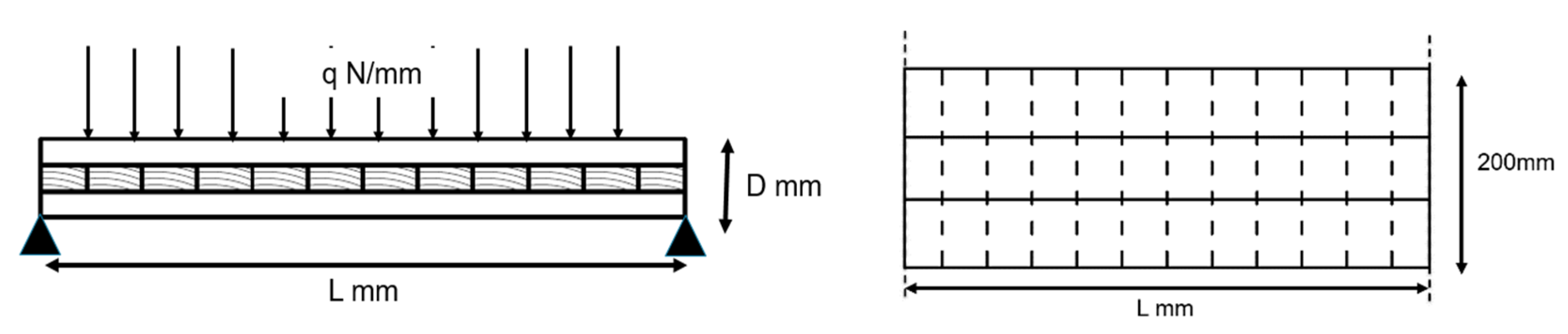
Figure 4.
(a) The experimental test setup and (b) illustration of geometric dimensions of the test specimen (all measurements in mm).
Figure 4.
(a) The experimental test setup and (b) illustration of geometric dimensions of the test specimen (all measurements in mm).
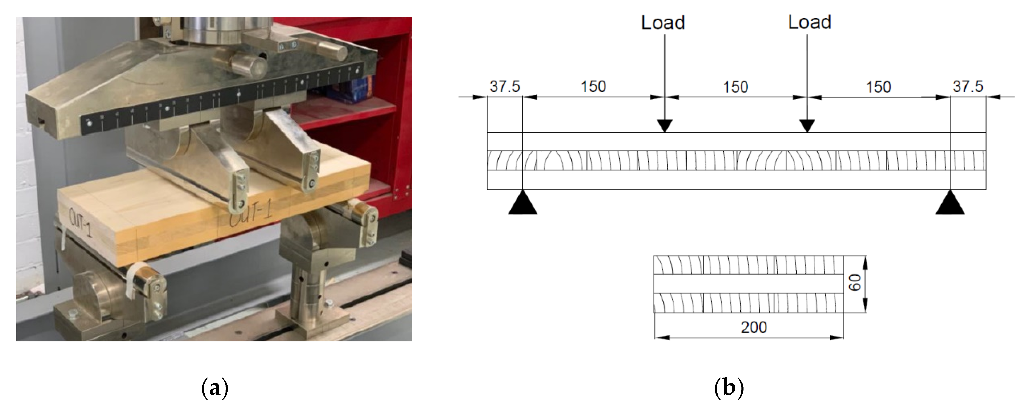
Figure 5.
The (a) FE model with rolling shear stress (shear stress radial–tangential plane) profile and (b) load-displacement results from the experimental tests and FE model.
Figure 5.
The (a) FE model with rolling shear stress (shear stress radial–tangential plane) profile and (b) load-displacement results from the experimental tests and FE model.
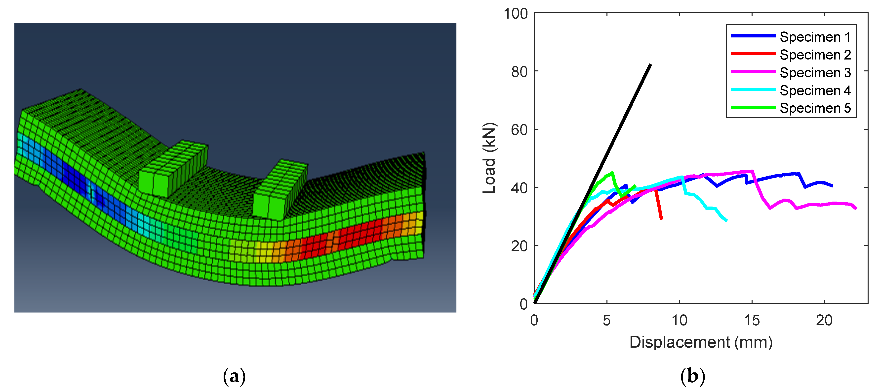
Figure 6.
Deviations in deflection predictions obtained using FE models vs. analytical methods.

Figure 7.
Comparison between FE predictions for CLT deflections vs. analytical predictions using Timoshenko method: (a) 90 mm thick CLT panels, (b) 120 mm thick CLT panels, (c) 150 mm thick CLT panels and (d) 180 mm thick CLT panels
Figure 7.
Comparison between FE predictions for CLT deflections vs. analytical predictions using Timoshenko method: (a) 90 mm thick CLT panels, (b) 120 mm thick CLT panels, (c) 150 mm thick CLT panels and (d) 180 mm thick CLT panels

Figure 8.
Deviations of analytical vs. FE shear stiffness for the considered CLT panels: (a) 90 mm thick CLT panels, (b) 120 mm thick CLT panels, (c) 150 mm thick CLT panels and (d) 180 mm thick CLT panels.
Figure 8.
Deviations of analytical vs. FE shear stiffness for the considered CLT panels: (a) 90 mm thick CLT panels, (b) 120 mm thick CLT panels, (c) 150 mm thick CLT panels and (d) 180 mm thick CLT panels.
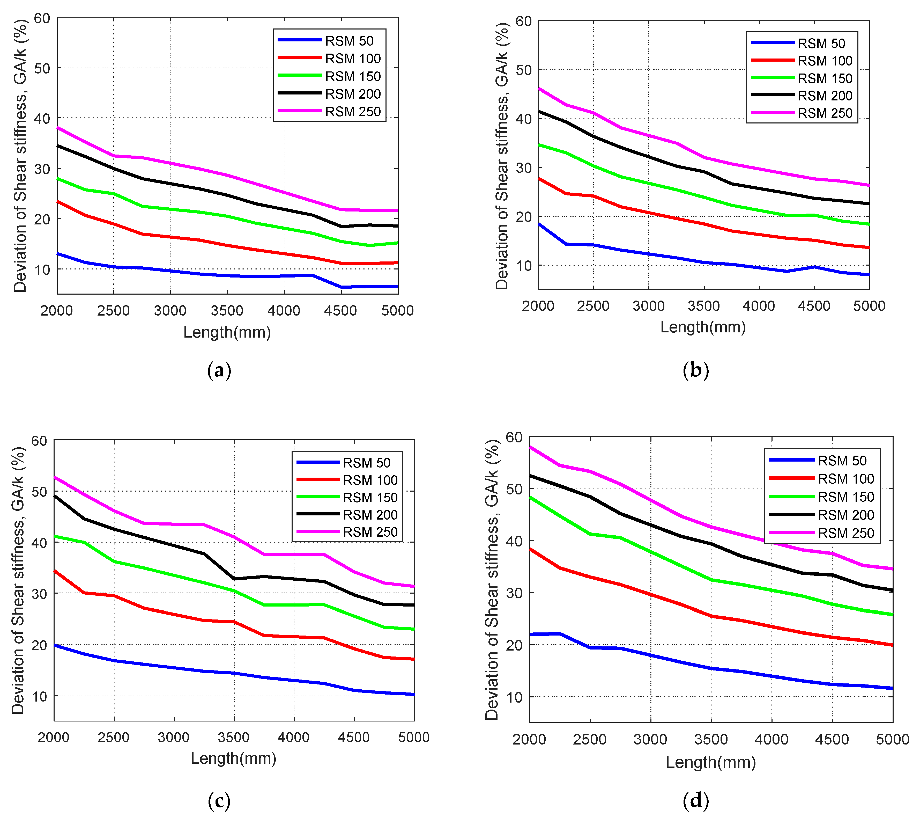
Figure 9.
Variation of (a) deflection and (b) shear stiffness of the section of panel with length to depth ratio of 11.11.
Figure 9.
Variation of (a) deflection and (b) shear stiffness of the section of panel with length to depth ratio of 11.11.
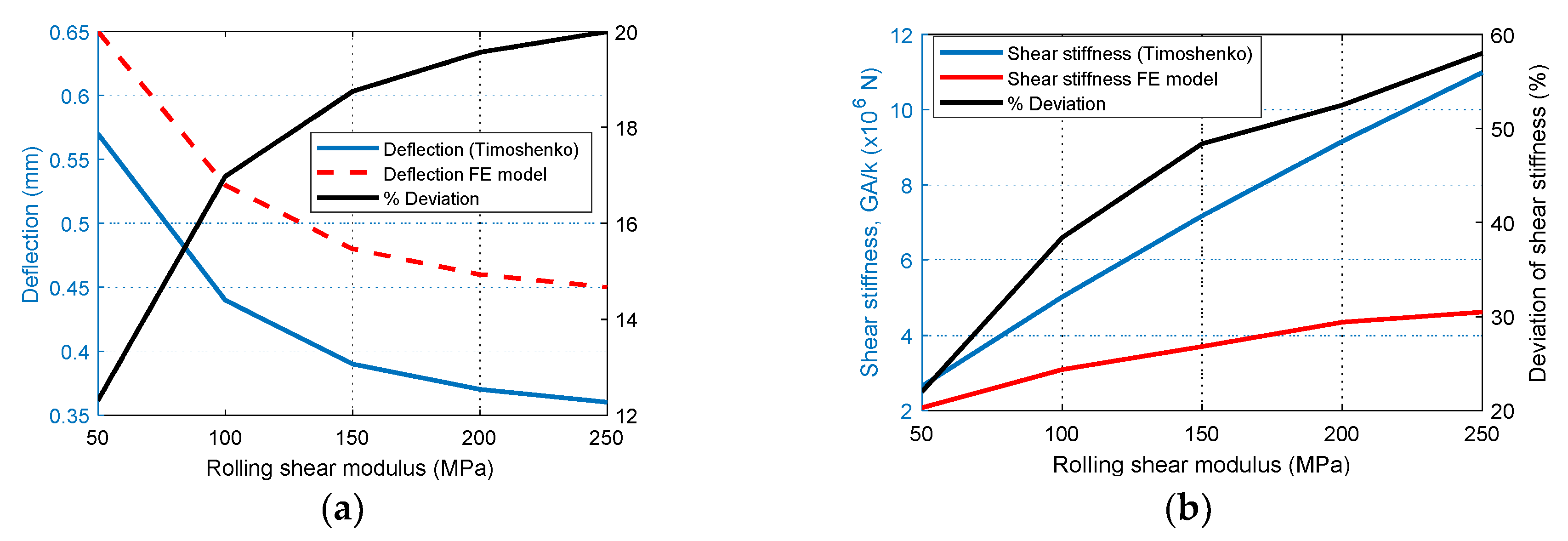
Figure 10.
Deviation of (a) deflection and (b) shear stiffness against changing span-to-depth ratio of Timoshenko method from FE models.
Figure 10.
Deviation of (a) deflection and (b) shear stiffness against changing span-to-depth ratio of Timoshenko method from FE models.
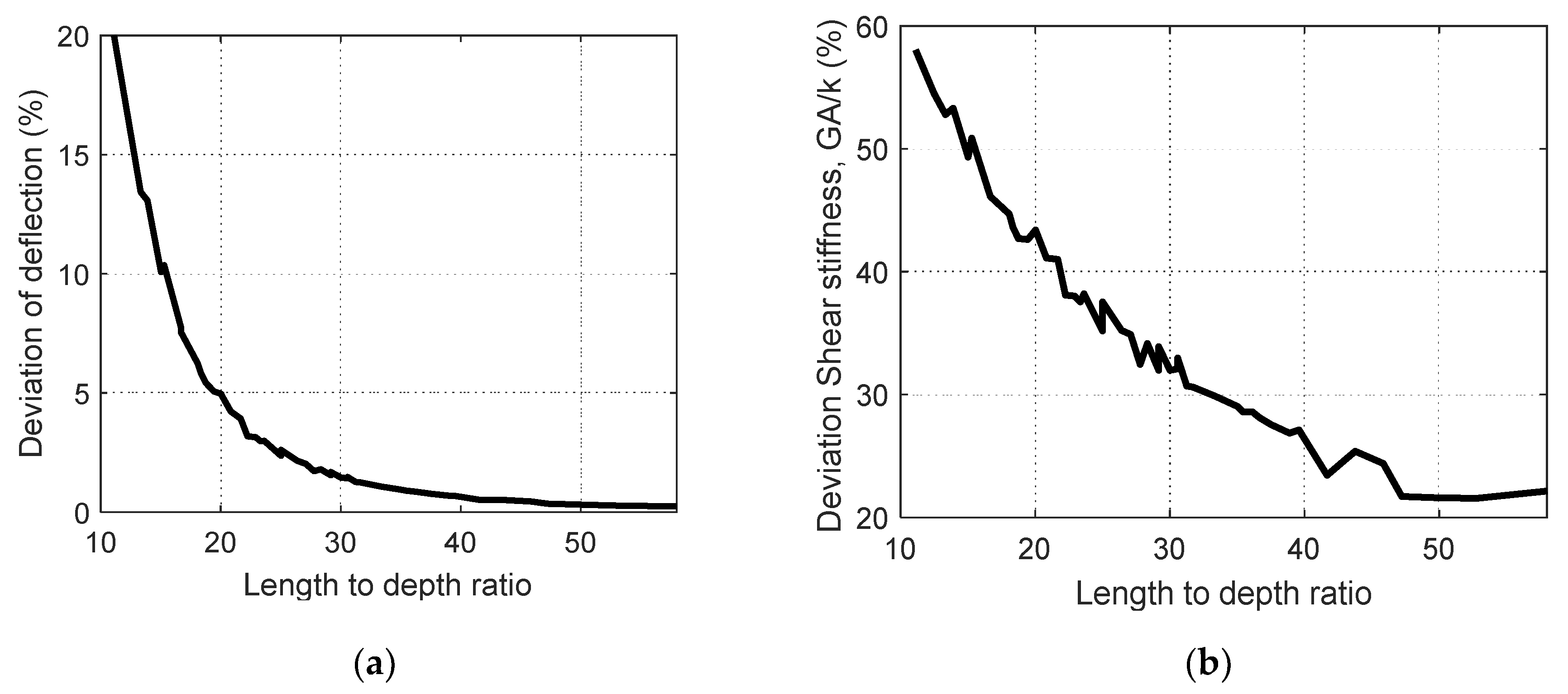
Figure 11.
Variation of shear stiffness with changing length for panels of thickness 90 mm and 180 mm for cross-layer characterized by 250 MPa rolling shear modulus.
Figure 11.
Variation of shear stiffness with changing length for panels of thickness 90 mm and 180 mm for cross-layer characterized by 250 MPa rolling shear modulus.
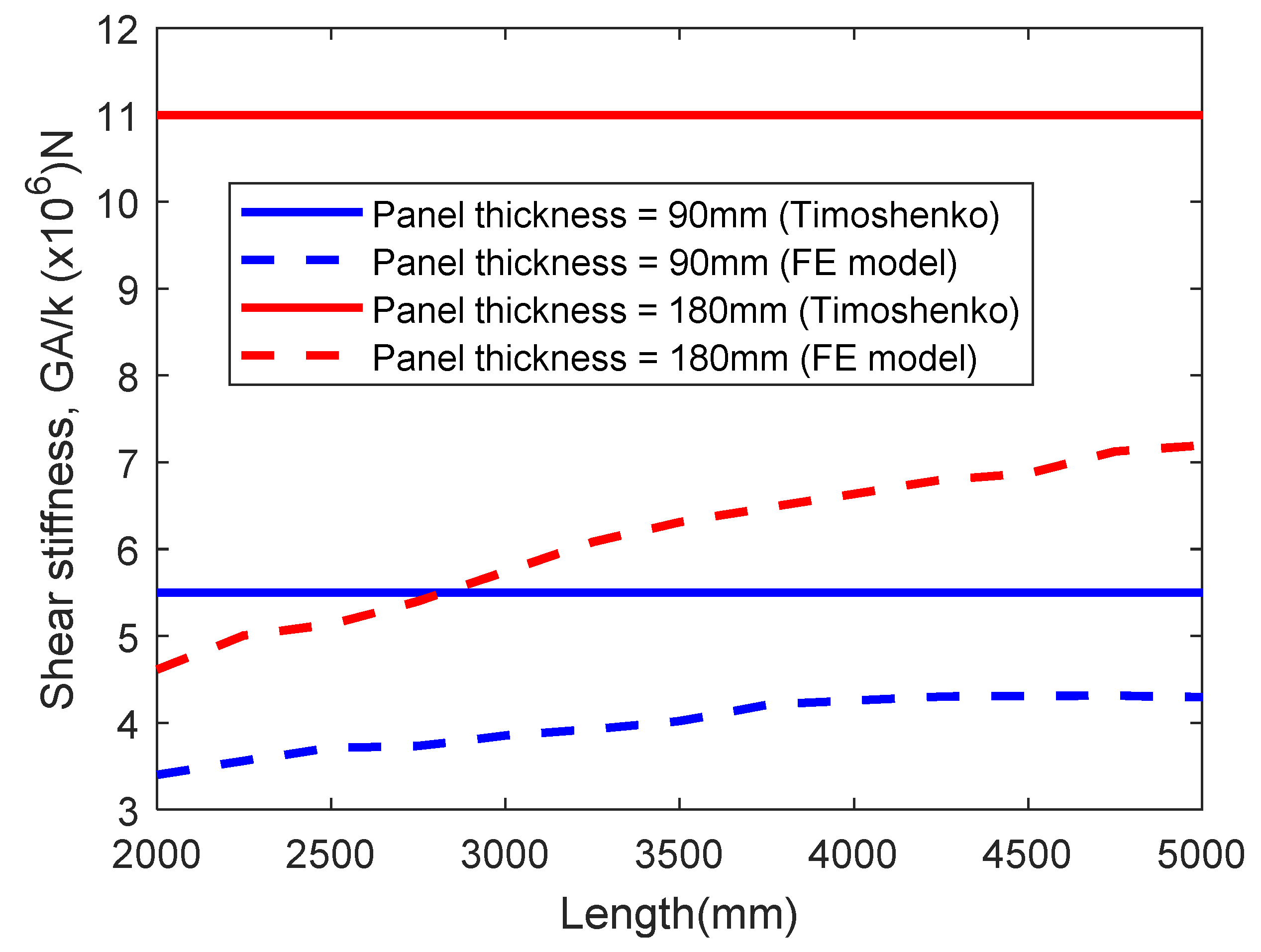
Figure 12.
Deviation of shear stiffness of Timoshenko theory to that estimated from Numerical model for panel thickness of 90 mm and 180 mm where cross-layers are characterized by 250 MPa rolling shear modulus.
Figure 12.
Deviation of shear stiffness of Timoshenko theory to that estimated from Numerical model for panel thickness of 90 mm and 180 mm where cross-layers are characterized by 250 MPa rolling shear modulus.
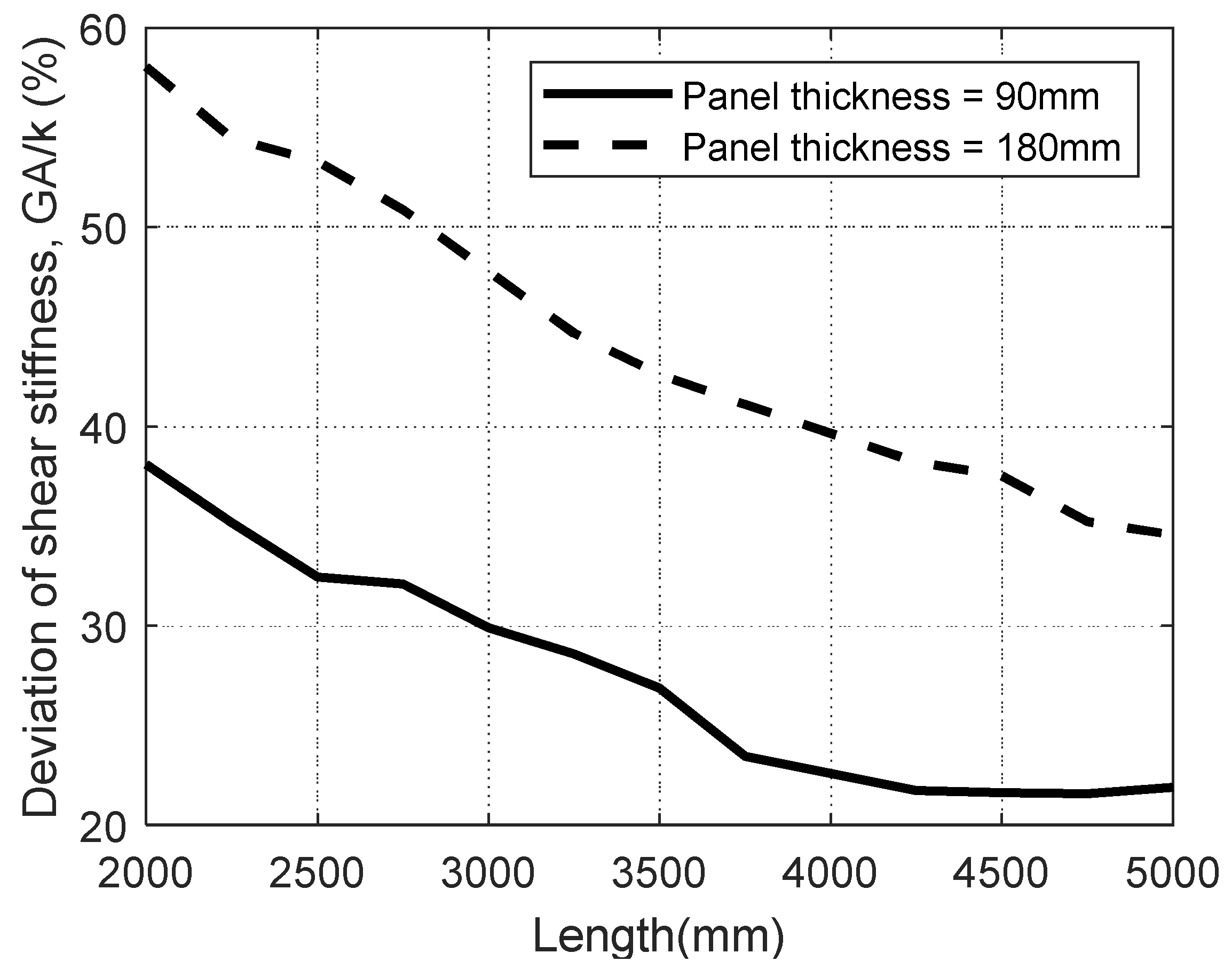
Figure 13.
Methodology to determine the shear correcting factor.

Figure 14.
Variation of the proposed modification co-efficient with (a) Rolling shear modulus, (b) Length and (c) Depth.
Figure 14.
Variation of the proposed modification co-efficient with (a) Rolling shear modulus, (b) Length and (c) Depth.
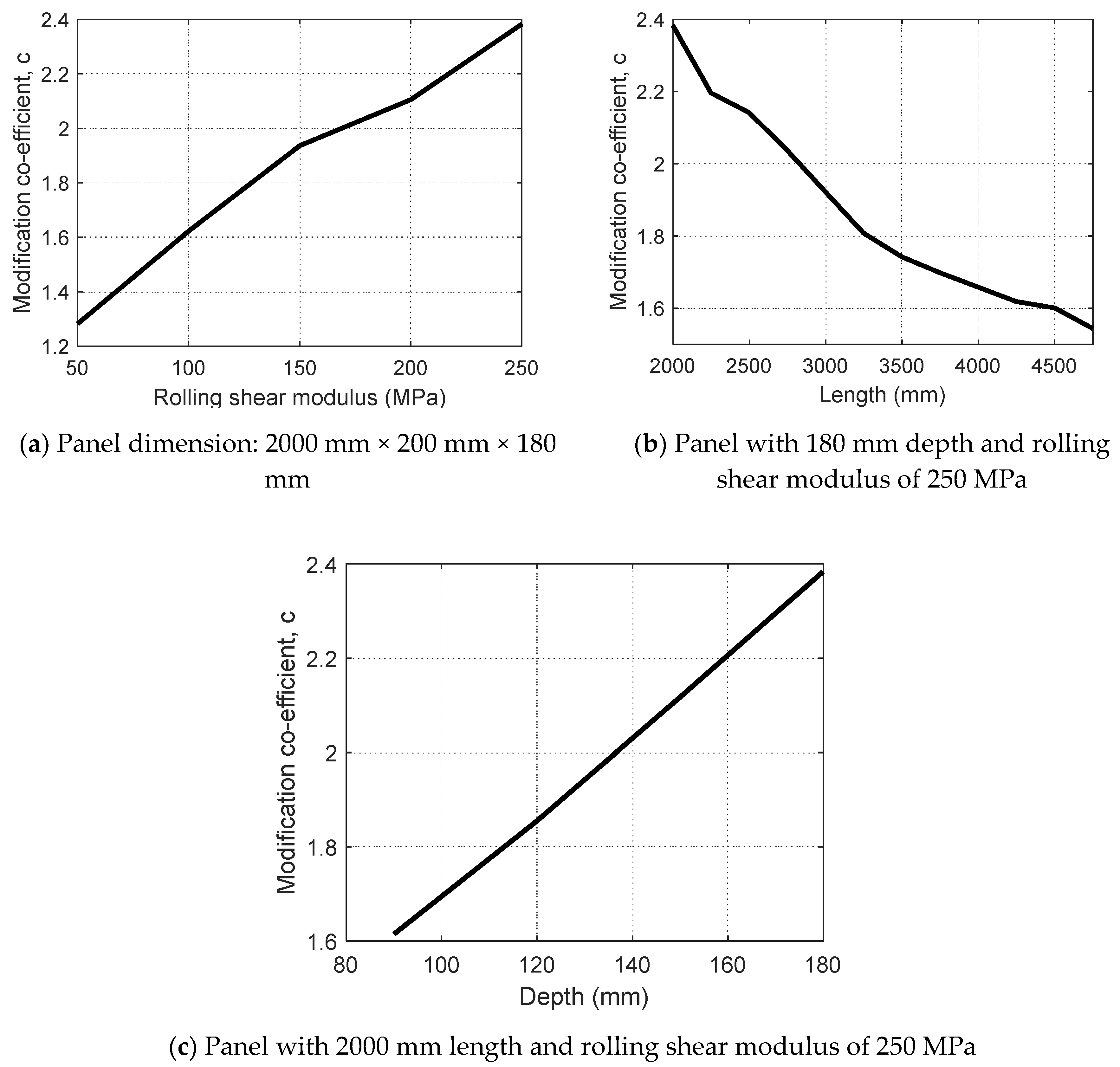
Figure 15.
Modification co-efficient against length. (a) 90 mm thick CLT panels, (b) 120 mm thick CLT panels, (c) 150 mm thick CLT panels and (d) 180 mm thick CLT panels.
Figure 15.
Modification co-efficient against length. (a) 90 mm thick CLT panels, (b) 120 mm thick CLT panels, (c) 150 mm thick CLT panels and (d) 180 mm thick CLT panels.
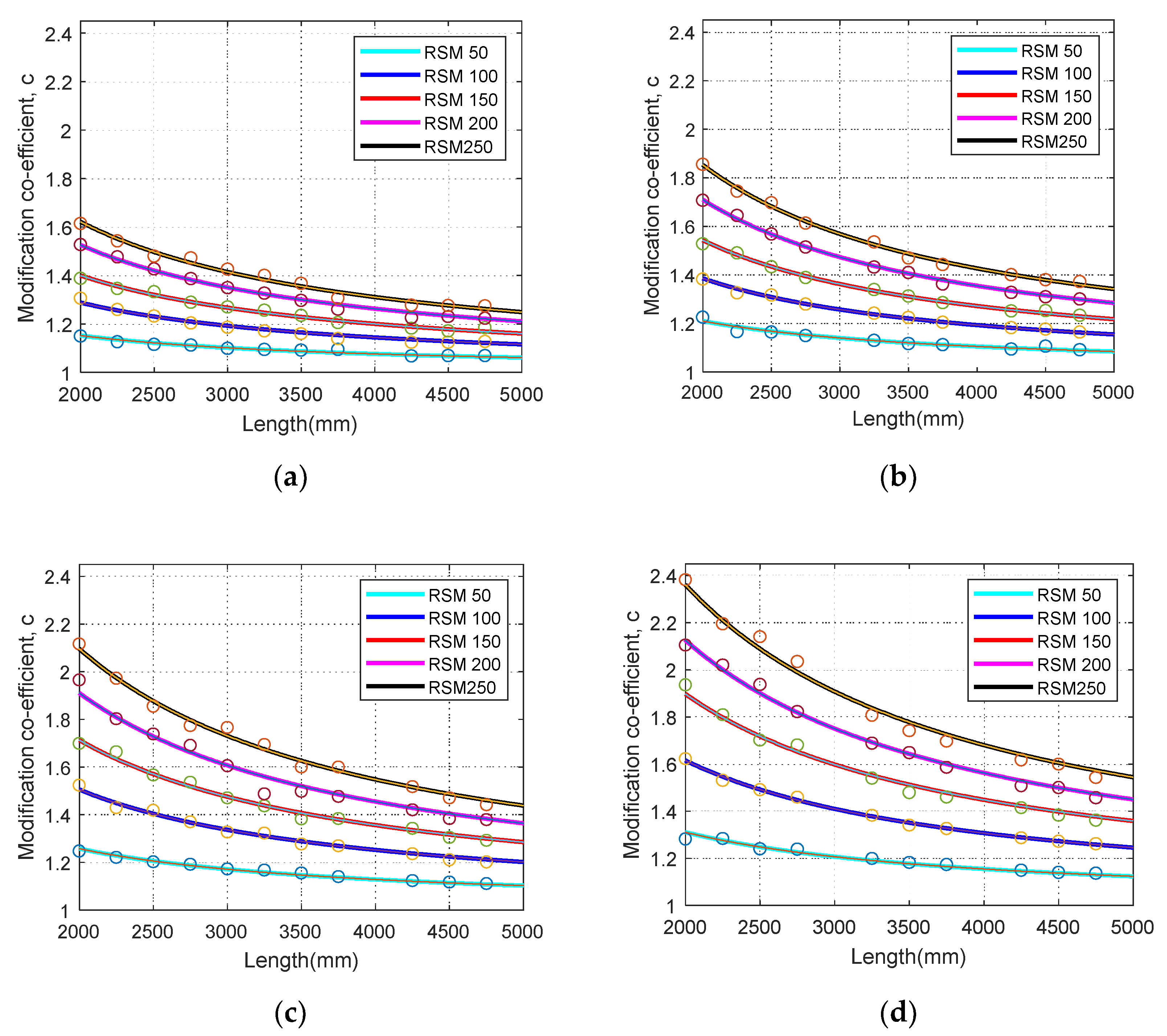
Figure 16.
Illustration of four-point bending set up [36].
Figure 16.
Illustration of four-point bending set up [36].


Table 1.
Elastic constants for orthotropic and transversely isotropic material models.
| Elastic Property | Direction | Transversely Isotropic Material |
|---|---|---|
| Elastic Modulus | Longitudinal direction | EL |
| Radial direction | ER = ET | |
| Tangential direction | ||
| Poisson’s ratio | Characterizing tangential normal strain to longitudinal normal strain | = |
| Characterizing radial normal strain to longitudinal normal strain | ||
| Characterizing normal tangential strain to radial strain | = | |
| Shear modulus | Longitudinal–tangential plane | GLT = GLR |
| Longitudinal–radial plane | ||
| Radial–tangential plane |
Table 2.
Mechanical properties used in FE models and analytical methods to calculate deflections.
| Characteristic Mechanical Property | Elastic Modulus (MPa) | Poisson’s Ratio | Shear Modulus (MPa) | |||||
|---|---|---|---|---|---|---|---|---|
| EL | ER/ET | GLR | GLT | GRT | ||||
| Longitudinal layer | 11,600 | 370 | 0.014 | 0.014 | 0.21 | 690 | 690 | 50 |
| Cross-layer | 11,600 | Constrained * | 0.014 | 0.014 | 0.21 | 690 | 690 | 50–250 |
* Constrained by transversely isotropic assumption to GRT and as shown in Table 1.
Table 3.
Mechanical properties used in FE models for validation against experimental results.
| Characteristic Mechanical Property | Elastic Modulus (MPa) | Poisson’s Ratio | Shear Modulus (MPa) | |||||
|---|---|---|---|---|---|---|---|---|
| EL | ER/ET | GLR | GLT | GRT | ||||
| Longitudinal layer | 11,000 | 370 | 0.014 | 0.014 | 0.21 | 690 | 690 | 50 |
Table 4.
Elastic modulus values used for the analytical methods for 3 layered CLT.
| Engineered Wood Product | Elastic Modulus (MPa) | Shear Modulus (MPa) | ||||
|---|---|---|---|---|---|---|
| Layer 1 E1 | Layer 2 E2 | Layer 3 E3 | Layer 1 G1 | Layer 2 G2 | Layer 3 G3 | |
| CLT | 11,600 | 370 | 11,600 | 690 | 50 | 690 |
| GLT | 11,600 | 11,600 | 11,600 | 690 | 690 | 690 |
Table 5.
Deflection estimated by Timoshenko method and FE models for glue laminated timber (GLT).
| Dimension (L × W × D) (mm × mm × mm) | Deflection (Timoshenko) (mm) | Deflection (Model) (mm) | Error (%) |
|---|---|---|---|
| 1026 × 200 × 60 | 0.57 | 0.55 | 3.5 |
| 1800 × 200 × 120 | 0.68 | 0.68 | 0 |
| 1800 × 200 × 90 | 1.57 | 1.54 | 1.9 |
| 2500 × 200 × 120 | 2.45 | 2.40 | 2 |
Table 6.
Mechanical properties of the species of timber used for validation.
| Species | EL (MPa) | ER/ET (MPa) | GLT/GLR (MPa) | GRT (MPa) | Reference |
|---|---|---|---|---|---|
| Irish sitka (Softwood) | 9900 | 772.2 | 633.6 | 61.88 3 | [29] |
| White pine (Softwood) | 8900 | 694.2 | 462.8 | 44.5 3 | [29] |
| Eucalyptus urophylla (Hardwood) | 13,391.7 | 640.70 | 897.24 1 | 267.83 2 | [37] |
| Red Maple (Hardwood) | 11,300 | 1582 | 1502 | 203.4 2 | [29] |
| White Ash (Hardwood) | 12,000 | 1536 | 1308 | 216 2 | [29] |
Table 7.
Deflection at 20 kN load for four point bending test.
| Species | Geometry (l × w × h) (mm) | a (mm) | EIglobal (×1010 N/mm2) | Experimental vs. Analytical Predictions | |
|---|---|---|---|---|---|
| δTM/δTest * | δmTM/δTest | ||||
| Irish Sitka [40] | 1440 × 270 × 60 | 540 | 3.69 | 0.939 | 0.963 |
| 1728 × 288 × 72 | 648 | 6.64 | 0.917 | 0.941 | |
| 2880 × 584 × 120 | 1080 | 63.61 | 0.936 | 0.962 | |
| 1440 × 584 × 120 | 360 | 39.44 | 0.806 | 0.922 | |
| Eucalyptus urophylla [40] | 1620 × 305 × 54 | 540 | 4.59 | 0.786 | 0.938 |
| White pine [38] | 2992.5 × 300 × 105 | 997.5 | 17.5 | 0.812 | 0.824 |
| Red Maple [38] | 2992.5 × 300 × 105 | 997.5 | 28.6 | 0.944 | 0.960 |
| White Ash [38] | 2992.5 × 300 × 105 | 997.5 | 30.6 | 0.952 | 0.970 |
* δTest, Deflection obtained from experiment; δTM, Deflection obtained from Timoshenko method; δmTM, Deflection obtained from modified Timoshenko method.
© 2020 by the authors. Licensee MDPI, Basel, Switzerland. This article is an open access article distributed under the terms and conditions of the Creative Commons Attribution (CC BY) license (http://creativecommons.org/licenses/by/4.0/).
Share and Cite
MDPI and ACS Style
Rahman, M.T.; Ashraf, M.; Ghabraie, K.; Subhani, M. Evaluating Timoshenko Method for Analyzing CLT under Out-of-Plane Loading. Buildings 2020, 10, 184. https://doi.org/10.3390/buildings10100184
AMA Style
Rahman MT, Ashraf M, Ghabraie K, Subhani M. Evaluating Timoshenko Method for Analyzing CLT under Out-of-Plane Loading. Buildings. 2020; 10(10):184. https://doi.org/10.3390/buildings10100184
Chicago/Turabian StyleRahman, MD Tanvir, Mahmud Ashraf, Kazem Ghabraie, and Mahbube Subhani. 2020. "Evaluating Timoshenko Method for Analyzing CLT under Out-of-Plane Loading" Buildings 10, no. 10: 184. https://doi.org/10.3390/buildings10100184
Note that from the first issue of 2016, this journal uses article numbers instead of page numbers. See further details here.