Abstract
Seismic events have repeatedly highlighted the vulnerability of existing masonry buildings. Seismic retrofitting is frequently focused on improving the connection between walls and roof for ensuring behavior able to resist loads from any horizontal direction. This paper deals with the design of masonry ring-beams made of clay bricks reinforced by natural fibers. Various solutions to ensure a masonry building box-behavior are possible, but this is a good combination of both static and conservation requirements, as it allows the use of bio-composites and grouts. It is a relevant possible alternative to the traditional reinforced concrete ring-beams, which are proven to be very ineffective under earthquakes. A simplified model for designing clay brick beams reinforced by flax fibers is provided, and a comparison with customary and traditional floor/roof masonry ring-beams is carried out.
1. Introduction
Earthquakes constantly highlight the high seismic vulnerability of existing masonry buildings: they usually have got great resistance against loads-inducing compression (self-weight, dead and live loads), but low capacity against seismic loads which frequently induce incompatible stress states [1,2,3,4,5]. Most historic buildings frequently present unreliable behavior under earthquakes because of detachments and loss of connections among walls and floors [6,7]. In this context, one goal of seismic retrofitting is the improvement of the building unitary response, ensuring a box-behavior. Roofs could be “adequately but not excessively” stiffened in their plane to supply enough distribution capacity of seismic forces among walls, but, above all, walls and floors have to be efficiently connected each other to ensure the capability to withstand horizontal loads and prevent out-of-plane failures [8,9].
Over the past years, the introduction of slabs and ring-beams in reinforced concrete (so versatile and modern as far from the masonry mechanical behavior), the loss of sensibility in understanding the historic building behavior and the lack of knowledge on old materials and techniques often produced inadequate retrofitting, unable to achieve their main purpose, sometimes with catastrophic consequences [3,10,11,12].
A suitable retrofitting can be achieved through floor tie-rods and ring-beams in reinforced masonry at the roof level. The main aim of this paper is therefore to compare the strength capacity of masonry ring-beams made of clay bricks reinforced by flax fiber fabrics to one of the more widespread and traditional techniques.
Ring-beams subjected to loads which are both orthogonal and parallel to bed joints and designed by both a simple and quick procedure and a more refined finite element modeling, are analyzed.
Masonry Ring-Beams Reinforced by Natural Fibers
Floor ring-beams develop an important role in the seismic behavior of masonry buildings: they connect orthogonal walls, receive the horizontal loads due to earthquakes from floors and convey them to walls, undergo thrusts from roof beams, favor the structure box behavior thwarting out-of-plane failures [13]. Solutions based on several materials are available to achieve some of these needs: each has its advantages and disadvantages, whereby some static performances prevail.
Concrete ring-beams can bear large axial and bending forces, but are too heavy and stiff; additionally, they are not capable of adequately distributing vertical loads on the underlying masonry because of their high stiffness. The high stiffness may cause redistribution of vertical compressive stresses, and some masonry portions could result in becoming unloaded and prone to being unstable during earthquakes; additionally, the high stiffness can modify the natural vibration mode of masonry walls, thus inducing local high stresses in the masonry below [14,15,16,17,18]. Furthermore, such a strengthening technique was frequently combined with new r/c floor slabs, adding masses to the building structure, increasing the earthquake-induced inertia forces, and consequently, the stresses in masonry walls. Moreover, the analysis of damages due to several earthquakes showed that the high stiffness of r/c beams and roofs, combined with inadequate connections to the underlying masonry walls, induced the out-of-plane failure of masonry walls [19]. Roofs monolithically poured with ring-beams in case of r/c are very stiff in their plane, and under earthquakes, have different behavior from the underlying masonry. The connection of r/c ring-beams with underlying walls would be effective only if it is made through proper and diffuse vertical perforations. The latter, however, can be particularly invasive and unsuitable in the case of poor masonry in terms of quality or blocks arrangement. Fiber-reinforced masonry ring-beams are an ordinary continuation of the masonry below (joined to it by a mortar layer), have similar deformation characteristics, and if necessary, can be well connected to the underlying walls by folding up the reinforcement fabrics on the vertical faces of the walls. This last connection is a specific advantage of the use of fabrics as reinforcement. The connection of ring-beams to the roof can, on the other hand, be carried out using the same techniques adopted for masonry beams reinforced by steel bars, which are now common in the strengthening of masonry structures [17,20]. Finally, as well as for mechanical reasons, concrete is incompatible with many masonry types for chemical-physical reasons.
On the other hand, reinforced brick masonry beams can be used for retrofitting the masonry buildings because of their well-matched mechanical properties, suitable compressive strength, availability, good compatibility, durability and low cost.
Following the rules of environmental protection, several composites based on natural fibers started to be more widespread as a tool for strengthening masonry buildings; and different fibers have been introduced in civil engineering [21,22,23]: bamboo, hemp, flax, jute, sisal, coir and cotton.
Fiber-reinforced composite materials based on natural fibers have advantages in terms of high tensile strength and lightness, as shown in the researches performed by Speranzini and Agnetti in 2012 [24] and earlier in 2010 [25], as well as in terms of production costs, pollution emissions and energy consumption for their production and disposal [21,26,27]. Besides, the cost of the disposal at the end of their life is generally significantly cheaper than the one of artificial composite materials.
Therefore, composites reinforced by natural fibers have attracted the interest of researchers over the last years [28,29,30,31,32,33,34,35,36,37], and if all of the positive features associated with the use of natural fibers are evaluated with the advantages of inorganic matrices, the use of these new sustainable composites is revealing to be a promising area of research and application. In fact, by using inorganic matrices instead of the organic ones, the compatibility with masonry substrates is improved [38] if compared to the more traditional fiber-reinforced polymers [39]. Furthermore, these strengthening systems can be applied in a wet environment [38,40,41], in the presence of dust, and they also exhibit good performance at elevated temperatures.
This paper focuses the attention on the retrofitting of existing masonry buildings through roof masonry ring-beams reinforced by flax fibers, and on the possibility of using simple numerical procedures for their design. Such beams allow overcoming many of the now well-known problems that were recognized to be due to r/c beams. This strengthening system was recently studied in some researches by other Authors [42,43,44,45,46], while the validation of this reinforcement solution for masonry beams was verified by experimental tests on full-scale beams reinforced by glass fiber-reinforced polymer composite [28]. Several specimens were tested under cyclic flexure and long duration loading. The results [28] show that such types of reinforced masonry ring-beams can be conveniently used to substitute traditional r/c ring-beams, with an advantage in lower weight and better material compatibility.
2. Materials and Methods
Ring-beams for seismic retrofitting of masonry buildings at the roof level are supported by the below masonry piers, and are subject to bending moment in correspondence of the underlying windows; sometimes they are built above the existing spandrel beams. Figure 1a,b respectively show reinforced masonry ring-beams under loads orthogonal and parallel to the bed joints. In the second case, the masonry wall is stressed out of the plane under seismic loading.
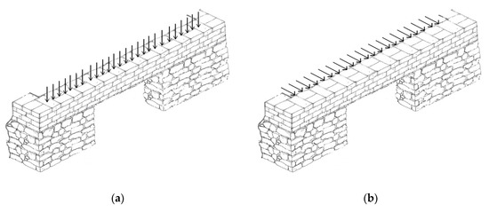
Figure 1.
Reinforced masonry beams differently loaded with respect to the bed joints: (a) Loads orthogonal to the mortar layers; (b) Loads parallel to the mortar layers.
2.1. Materials
The geometry of the analyzed beams was determined according to the wall geometry of typical masonry buildings frequently found in seismic areas of Southern Italy [47]. Therefore, the beam width is constantly assumed equal to 600 mm, whereas the height is varied by varying the brick height and the number of clay bricks layers: the latter is varied from a minimum of three to a maximum of six. A reinforcing layer formed by flax fiber fabric is always interposed among them, and a natural hydraulic lime mortar mix is used to produce fiber-reinforced, cementitious matrix composite materials.
Solid and hollow commercial clay bricks for masonry structures are considered: all of them are 250 mm long and 115 mm wide, while the height varies: the solid bricks are 60 mm thick, while the hollow ones are 60 mm and 120 mm thick. The normalized compressive strengths of bricks are summarized in Table 1.

Table 1.
Mechanical characteristics of commercial solid and clay bricks.
High-strength, flax fiber fabrics (unidirectional double layer) 0.267 mm thick are used as reinforcement. The main properties of flax fabric impregnated with mortar are reported in Table 2.

Table 2.
Properties of flax fabric impregnated with mortar.
Even the elastic moduli are kept constant: 4000 MPa for clay bricks and 43,000 MPa for flax fibers. The material partial factors used to compute the corresponding design strengths are determined according to the Italian technical regulation in force, as it provides the values for both masonry and fibers. For masonry of class 2 (built with the availability of specific qualified and experienced personnel under inspection) made of bricks of category I (units with declared compressive strength and probability of failure not greater than 5%) and mortar with prescribed composition, the partial factor γm is equal to 2.7 [48]. For fiber-reinforced systems in which only materials are certified (type A applications), and for which the most likely failure is considered to be due to composite detachment, the partial factor γf is equal to 1.5 [49]. All of the above values are used in both the simplified and the finite element modeling.
2.2. Methods
The seismic safety verification and the strengthening design of masonry buildings can be performed through 3D and 2D finite element models [50] or by simplified models, where piers and spandrel beams are modeled by one-dimensional elements, as advised by several codes [48]. In the latter case, reinforced masonry ring-beams at the roof level could be modeled by further beams, assigning them adequate behavioral characteristics and load-bearing capacity in terms of axial force, shear force and bending moment.
Within a simplified approach, the capacity in terms of axial and shear force is immediately determined, whereas the evaluation of the bending capacity requires a simplified but suitable procedure to compute the resisting moment.
In this context, the reinforced ring-masonry beams can be designed similarly to the RC ones: therefore, in this paper, the classical technical beam theory used to calculate the strength of RC beam cross-sections is adapted to the masonry section reinforced by flax fibers [51,52]. The ultimate strength under bending stresses is computed by considering a linear elastic behavior for both reinforcement and masonry units [53]. This allows a quick sizing of reinforced masonry beams under loads orthogonal and parallel to the mortar joints in the retrofitting of existing masonry structures.
Therefore, the simplified design of masonry sections reinforced by flax fibers is simply performed under the customary basic assumptions of the flexural theory: (i) plane sections remaining plane (Bernoulli’s principle); (ii) strains in bricks and reinforcing fibers are equal at the same level, provided that the bond between fiber-reinforced cementitious matrix composites and bricks is sufficient to keep them acting together under the different load stages (no slip can occur between the two materials); (iii) brittle behavior for both materials (materials are linearly elastic and do not deform plastically); (iv) materials are assumed to be isotropic and homogeneous; (v) tensile strength of bricks may be neglected; (vi) fiber composite does not resist to compression.
The assumption regarding the bond between bricks and fiber reinforced cementitious matrix composite materials is a well-established hypothesis for this reinforcing technique, and is also based on excellent results achieved in experimental researches. In Codispoti et al. [34], Cevallos et al. [46] and Olivito et al. [54] it is shown that flax fiber reinforced cementitious matrix have a good bond behavior with the masonry support; it is also shown how flax fibers made full use of their mechanical properties in the composite during the tests performed.
The hypothesis concerning the compressive strength of masonry (brittle behavior) requires a deepening, since it is considered one of the most important assumptions. It is known that the manufacturing of clay and shale masonry units (raw materials, production technique and baking temperature) strongly influences their sizes and physical properties. Commercial clay bricks are usually produced by extrusion molding, and frequently exhibit an almost linear stress–strain curve up to the maximum strength, and a sudden drop in stress values after the peak, with a small increment in strains. The softening behavior of clay bricks after the peak stress is extensively described in several research papers [55]. It is a salient feature of these quasi-brittle materials because of the progressive internal crack growth. This is due to material defects (flaws and voids), inclusions and micro-cracks arising from the shrinkage during the burning process. Initially, the micro-cracks are stable and grow only when the compressive load is increased. Around the peak stress, the formation of macro-cracks starts: they are unstable and result in a sudden decrement of stresses and the localization of cracking in small zones only, whereas the rest of the brick unloads [55]. This behavior is in contrast to the cast and press historic brick units that have lower strengths and a larger capacity of deformation in uniaxial strain, with a more evident and stable inelastic response. Furthermore, it was often observed that most of the burnt clay brick prisms fail due to the formation of vertical splitting cracks along their height [56]. Finally, the commonly assumed bilinear compressive stress–strain curves for burnt clay bricks masonry is also attributed to brick cracking and mortar nonlinearities. In the case under examination, it was considered more conservative to assume a linear behavior without nonlinear excursions, and also because the realization of a beam reinforced with flax fibers would require somewhat thin layers of mortar, that inevitably allow minor inelastic adaptability.
Under the above assumptions, the equations for computing the resisting bending moments of a ring-beam reinforced by flax fibers are the following (Figure 2).
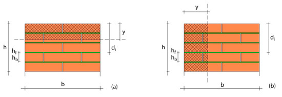
Figure 2.
Cross-section of reinforced masonry ring-beam: geometric parameters. (a) Bending due to loads orthogonal to the bed joints; (b) Bending due to loads parallel to the bed joints.
The beam is subjected to pure bending, because only vertical loads act. The neutral axis y, measured from extreme compressive fiber, can be computed using the balance of all forces acting on the beam cross-section (Figure 2a):
where b is the section width, nf is the total number of layers of reinforcing fiber, hb is the thickness of bricks, hf is the thickness of each fiber layer, nb is the number of clay bricks fully or partially compressed, n is the ratio of the modulus Eb of clay bricks to the modulus Ef of the reinforcing flax fiber, di is the distance of the center of each fiber layer from the upper edge of the section (numbered from the top of the section).
The resisting bending moment is provided by:
where h is the total height of the ring-beam, fc is the compressive strength of bricks at the section upper edge and ft is the tensile strength of the lowest fiber, in the stressed direction.
The computation of neutral axis and resisting bending moment requires an iterative solution: such a solution involves that one of the two strengths fc and ft is equal to the design strength of the corresponding material, while the other one is lower.
If the masonry beam is subjected only to loads parallel to the bed joints, clay bricks and flax fibers are loaded differently with respect to the previous case. The neutral axis y (measured from extreme compressive fiber) is computed by the following equation (Figure 2b), being the beam subjected to pure bending:
The resisting moment is provided by:
In this paper, the resisting bending moment of several reinforced masonry cross-sections is computed by the above equations and by a more refined 3D finite element modeling. In the latter case, a 3600 mm long beam is considered, with the aim of comparing the resistant bending moment of the mid-span cross-section of the beam under the same working conditions considered in the simplified model (achieving maximum compressive strength in the upper bricks or maximum tensile strength in the reinforcement fiber fabrics). A simply supported (pinned-hinged) beam is modeled when loads act orthogonally to the bed joints (Figure 3). In the case of bending due to loads parallel to the bed joints, the nodes at the beam vertical ends are constrained by hinge bearings, and the nodes at the lower ends are constrained by roller bearings (Figure 4). In both cases, the absence of further constraints in the lower nodes of the beam is due either to the presence of possible windows (the ring-beam works as a spandrel beam) or to a conservative assumption necessary to calculate the bending moment. The bricks are modeled by eight-node solid elements, considering the compressive strength of Table 1. Each brick has been divided into four solid elements: two in the direction of greatest length (and arranged in the longitudinal development direction of the beam) and two in height. The FEM analyses are performed using the computer program MidasGen®, using the well-known Drucker–Prager failure criterion [57], as a smooth version of the Mohr–Coulomb yield surface, suitable for materials that exhibit volumetric plastic deformations. The cohesion c and the friction angle φ are assumed equal to 0.14 MPa and 45°, respectively [58,59,60]. The flax fibers are placed inside the mortar beds as a fiber-reinforced cementitious matrix composite, and are modeled through “tension only” elements (Table 2). No slip is considered possible between bricks and fiber-reinforced cementitious matrix composites, since the bond is sufficient to keep them acting together under the different load stages, as previously explained for the simplified procedure. The FEM model is composed of minimum 1260 and maximum 3180 elements, due to the variation in the number of clay bricks layers. Figure 3 and Figure 4 show the model of beams made of five layers of solid bricks 60 mm thick (therefore with four layers of fiber-reinforced cementitious matrix composite).

Figure 3.
Finite Element Model (FEM): constraints of a beam made by five layers of solid clay bricks 60 mm thick for loading orthogonal to the bed joints.

Figure 4.
Finite Element Model: constraints of a beam made by five layers of solid clay bricks 60 mm thick for loading parallel to the bed joints.
3. Results
The resisting bending moment of several masonry cross-sections is computed through both the simplified Equations (2) and (4) and the more complete nonlinear finite element modeling previously introduced. Subsequently, the first values are compared to the ones of the ring-beams made by other materials.
In the FEM analysis, a uniformly distributed load acting in the vertical direction over the entire upper surface of the beam is increased in the case of loads perpendicular to the mortar layers, in addition to the beam self-weight. In the case of loads parallel to the mortar layers, the distributed load is applied in the horizontal direction over the entire front surface of the beam. The bending moments are computed by integrating the normal stresses acting in the mid-span cross-section of the masonry beam when one of two materials (clay brick and flax fiber) reaches its failure condition.
The beam failure is usually computed assuming a maximum strain, defined as the strain corresponding to stress equal to a predetermined percentage (usually 80%) of the peak stress in the post-peak region. This assumption of failure strain does not apply in the case of the examined burnt clay brick masonry, since, as previously reported, after reaching the peak stress, a sudden drop in stress value is frequently observed with a small increment in strains. Thereafter, the strain could increase with a higher rate due to the evident crushing of masonry, and this should not be allowed in the ring-beams studied in this paper, which should be used as strengthening elements. This explains why a brittle behavior is assumed for masonry, and an elastic calculation without post-critical behavior is advised: therefore, the failure condition is assumed to correspond to the achievement of maximum design compressive strength in bricks or tensile strength in flax fiber fabrics.
Figure 5 shows the load-displacement curve (computed at the mid-span) of a beam made of five layers of solid bricks 60 mm thick (and then four layers of impregnated flax fibers) subjected to loads orthogonal to the mortar beds (vertical loading).
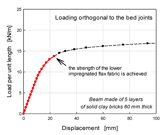
Figure 5.
FEM: load-displacement curve for masonry beam reinforced by flax fiber under vertical loads.
The figure shows the load at which the design tensile strength of the lower layer of flax fiber reinforcement is achieved, while the maximum compressive stress in the bricks is lower than the design one. This condition corresponds to the failure condition in the simplified method. After this point, as loads increase, the other layers of flax fibers reach their design strength and the vertical displacements increase very quickly.
Figure 6 shows the distribution of normal stresses in the same beam as Figure 5 when the lowest flax fiber fabric is reaching the design tensile strength. The normal stresses in the mid-span cross-section are also shown in the Figure. A neutral axis at about 60 mm from the extreme compressive fiber can be identified, and the integration of such normal stresses leads to a resistant bending moment equal to 25.63 kNm. It can be remarked that the simplified procedure provides the neutral axis at 49 mm from the extreme compressive fiber and a resistant bending moment equal to 21.27 kNm.
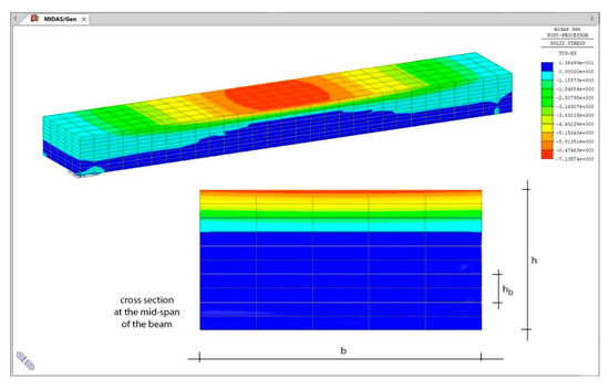
Figure 6.
Distribution of normal stresses [MPa] in the mid-span cross-section of the FEM masonry beam.
Figure 7 shows the resisting bending moments in beams made by several brick types and loaded orthogonally to the bed joints (bending in vertical planes). The moments are plotted as the beam height (that is, the number of brick layers) varies. The continuous lines show the bending moments provided by the FEM model analysis, the dotted lines the ones obtained by the simplified procedure. The red lines represent solid brick masonry (SB), the black lines hollow brick masonry (HB).
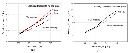
Figure 7.
Resisting bending moments of masonry beams reinforced by flax fibers for loads orthogonal to the bed joints: (a) solid and hollow bricks 60 mm thick; (b) hollow bricks 120 mm thick.
The curves in Figure 7a show that as the number of brick layers increases, the simplified procedure underestimates the resisting moment with respect to FEM analysis, mainly in the case of bricks 60 mm thick. The error is still bounded within about 20%, except for the masonry beam made by seven layers of solid bricks 60 mm thick.
This is due to the different hypothesis on the clay brick behavior, since a linear behavior is assumed in the simplified model, while in the FEM model, the bricks are assumed to behave nonlinearly. In both models, the flax fibers work at maximum design strength, and the position of the neutral axis is almost the same. Therefore, for the same compression resulting force, in the FEM model, the bricks contribute more to the resisting moment, having a higher centrifugation (the resulting compression has a greater distance from the neutral axis).
This effect is lower in the case of bricks 120 mm thick (see Figure 7b), since the compression force is centrifuged even in the simplified model. On the other hand, it has been seen that assuming an elastic–plastic behavior in the simplified model (as often assumed for the masonry piers) would tend to overestimate the capability of the masonry ring-beam, as the number of clay bricks is small, that is in situations that have a greater recurrence in daily practice.
Figure 8 shows the load-displacement curve (computed at the mid-span) of the same beam of Figure 5 and Figure 6 subjected to loads parallel to the mortar beds (horizontal loading). The Figure shows the load level at which the most compressed bricks reach the design compressive strength: beyond this threshold, the response of the beam is no longer linear and the horizontal displacements increase rapidly. Such a threshold also corresponds to the failure condition used in the simplified method.
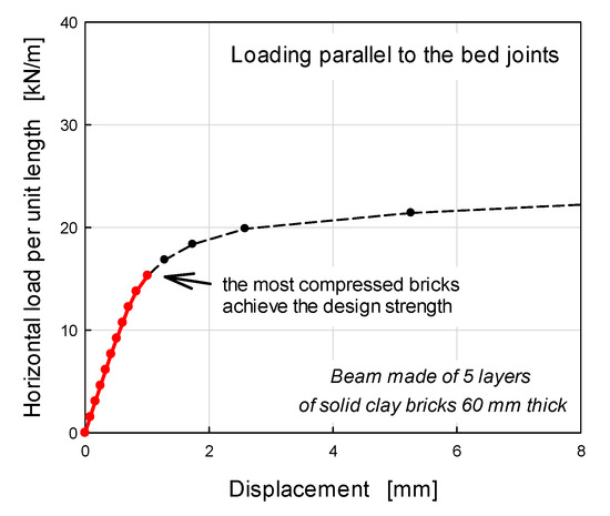
Figure 8.
FEM: load-displacement curve for a masonry beam reinforced by flax fiber under horizontal loads.
Figure 9 shows the resisting bending moments in beams loaded in the direction parallel to the bed joints (bending in horizontal planes). The curves show that, in this case, the two design approaches lead to similar values for beams made by solid or hollow bricks 60 mm thick (Figure 9a), and different values in beams made by hollow bricks 120 mm thick (see Figure 9b).
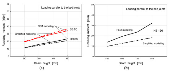
Figure 9.
Resisting the bending moments of masonry beams reinforced by flax fibers for loads parallel to the bed joints: (a) solid and hollow bricks 60 mm thick; (b) hollow bricks 120 mm thick.
Under these working conditions of masonry beams (loads parallel to the bed joints), the resisting moment is controlled by the brick strength, while even the flax fibers at the maximum distance from the neutral axis do not offer their maximum resistance. Therefore, the two models provide different neutral axis positions, which correspond to different contributions of bricks and flax fiber fabrics, and then to different resisting moments, mostly in the case of hollow bricks 120 mm thick.
In conclusion, Figure 7 and Figure 9 show an adequate capacity of the simplified modeling in assessing the resistant bending moments of masonry ring-beams reinforced by flax fibers, mainly for beams made by solid or hollow bricks 60 mm thick. This allows us, for example, to use this approach in the simplified modeling of an entire building structure, such as the masonry frame model usually used to perform pushover analyses [61,62].
4. Discussion
Figure 10 compares the resisting bending moments computed for masonry beams made of solid clay bricks 60 mm thick, reinforced by flax fibers (FFRG), with the ones calculated for two customary alternatives in different materials: clay masonry beams reinforced by stainless bars (R/M) and reinforced concrete beams (R/C). The first is a strengthening technique that has partially spread in recent times, and the second, as previously reported, should be excluded in the retrofitting of existing masonry buildings, although it is widespread.
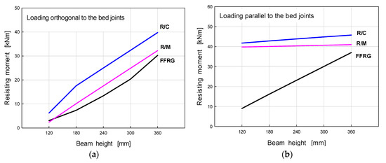
Figure 10.
Comparison among the resisting moments of ring-beams in several materials: (a) loads orthogonal to the bed joints; (b) loads parallel to the bed joints.
The beams have the same geometry as that reinforced by flax fibers. In both cases they are reinforced by three 16 mm diameter stainless steel bars both at the upper and lower edge, a framework widely used in everyday practice for strengthening existing masonry buildings; this reinforcement is kept constant as the height of the beam varies.
The resistant bending moment of reinforced concrete beams is computed using the usual assumptions of r/c beam theory, i.e., the parabola–rectangle diagram for concrete under compression and the bilinear stress–strain relation for reinforcement. Cylindrical concrete strength of 20 MPa and 235 MPa yield strength stainless steel are assumed. In this regard, it should be noted that the design tensile force provided by three 16 mm diameter bars is very close to that provided by the considered flax fibers. The partial factors for material strength are equal to 1.50 for concrete and 1.15 for steel [48].
In masonry beams reinforced by stainless steel bars, the linear distribution of stresses for masonry and bilinear relation for steel are adopted, assuming a maximum allowable strain of 0.002 and 0.01, respectively, (as required by numerous building codes). Partial factors for material properties of 2.70 for masonry and 1.15 for steel are assumed.
The comparison of Figure 10a (bending in vertical planes) shows that the masonry beams reinforced by flax fibers have slightly lower resistant moments than the other ones. The resisting moments rise with increasing the beam height because of the increasing number of fiber layers with the beam height for FFRG and the larger bars centrifugation for R/M and R/C.
When the beams are loaded in the horizontal plane, the resistant moment of the ones reinforced by flax fibers is much lower, especially in the case of low beams, and increases much more with the beam height (see Figure 10b). This is due to the larger number of fiber layers which, in the case of thick beams, contribute to the resistant moment, while in other cases the reinforcement is kept constant.
The above results, however, do not deny that masonry ring-beams reinforced by flax fiber fabrics can be a valid alternative to traditional r/c ring-beams that recent earthquakes have shown to be unsuitable for strengthening existing masonry structures. The increment of bricks and composite layers allows achieving ring-beams of size and height able to develop resisting moments sufficient to provide all of the needs in the seismic retrofitting of historic buildings (connection of orthogonal walls, distribution of the thrusts due to roof beams, building box behavior, thwarting of out-of-plane failures of below walls).
5. Conclusions
The strengthening of existing masonry buildings often requires the construction of ring-beams at the roof level to improve the connection among orthogonal walls, obtain a building box behavior, distribute the roof thrusts among the below walls, thwarting the out-of-plane failure of walls. For several years, r/c ring-beams were built, but numerous recent earthquakes have proven not to be a suitable solution. The r/c beams, in fact, have stiffness often disproportionate and unjustified for the function to be fulfilled, and present mechanical and physical incompatibility with the masonry material.
The paper shows that masonry ring-beams reinforced by flax fiber fabrics can be a valid alternative, since they allow the achievement of the aforementioned main purposes that are necessary to improve the seismic capacity of existing masonry buildings: it is shown that these beams develop resisting bending moments in both the horizontal and vertical planes similar to those of other more common or less reliable beam solutions. Furthermore, the availability of adequate resisting moments is coupled with deformation characteristics which are more compatible with the ones of the below masonry walls.
Masonry ring-beams reinforced by flax fibers are also a particularly suitable solution for retrofitting monumental masonry structures. They fully respond to requests of normative documents concerning the Seismic Risk Prevention of Cultural Heritage, where it is generally advised that the seismic improvement of historically–artistically relevant structures must be mandatorily achieved through interventions that enhance the seismic capacity without changing the main features of the structure. Masonry ring-beams reinforced by flax fibers fully comply with this request due to their high mechanical compatibility with historical masonry structures, to be both respectful of the original building system (in terms of materials and structural system) and completely reversible.
The paper also shows how simple analytical procedures are sufficient to design the aforementioned flax fiber-reinforced masonry beams. The beams can be designed according to the classical technical beam theory used to design r/c and masonry beam cross-sections, adapted to masonry sections reinforced by several layers of flax fibers. The hypotheses underlying this calculation are then illustrated and discussed in the paper, and it is shown how it allows a quick sizing under loads orthogonal and parallel to the bed joints.
Finally, comparisons among the resisting moments computed for masonry beams made of solid clay bricks reinforced by flax fibers, and the ones computed for two customary alternatives in different materials (that is, clay masonry beams reinforced by stainless bars and reinforced concrete beams), are shown and discussed.
Author Contributions
Conceptualization, M.G. and G.F.; methodology, M.G. and G.F.; software, G.F.; validation, M.G.; formal analysis, M.G.; resources, M.G.; data curation, M.G.; writing—original draft preparation, M.G.; writing—review and editing, M.G. and G.F. All authors have read and agreed to the published version of the manuscript.
Funding
This research received no external funding.
Acknowledgments
The contribute of Ministry of Education, University and Research and particularly the Basic Research Activities Fund (FFABR) is gratefully acknowledged.
Conflicts of Interest
The authors declare no conflict of interest. The funders had no role in the design of the study; in the collection, analyses, or interpretation of data; in the writing of the manuscript, or in the decision to publish the results.
References
- Gesualdo, A.; Cennamo, C.; Fortunato, A.; Frunzio, G.; Monaco, M.; Angelillo, M. Equilibrium formulation of masonry helical stairs. Meccanica 2017, 52, 1963–1974. [Google Scholar] [CrossRef]
- Como, M. Statics of Historic Masonry Constructions; Springer: Berlin/Heidelberg, Germany, 2013. [Google Scholar]
- Bergamasco, I.; Gesualdo, A.; Iannuzzo, A.; Monaco, M. An integrated approach to the conservation of the roofing structures in the Pompeian domus. J. Cult. Herit. 2018, 31, 141–151. [Google Scholar] [CrossRef]
- Marcari, G.; Manfredi, G.; Prota, A.; Pecce, M. In-plane shear performance of masonry panels strengthened with FRP. Compos. Part B 2007, 38, 887–901. [Google Scholar] [CrossRef]
- Park, J.; Towashirapornb, P.; Craigc, J.I.; Goodnod, B.J. Seismic fragility analysis of low-rise unreinforced masonry structures. Eng. Struct. 2009, 31, 125–137. [Google Scholar] [CrossRef]
- Cattari, S.; Degli Abbati, S.; Ferretti, D.; Lagomarsino, S.; Ottonelli, D.; Tralli, A. Damage assessment of fortresses after the 2012 Emilia earthquake (Italy). Bull. Earthq. Eng. 2014, 12, 2333–2365. [Google Scholar] [CrossRef]
- De Matteis, G.; Brando, G.; Corlito, V.; Criber, E.; Guadagnuolo, M. Seismic vulnerability assessment of churchs at regional scale after the 2009 L’Aquila earthquake. Int. J. Mason. Res. Innov. 2019, 4, 174–196. [Google Scholar] [CrossRef]
- Faella, G.; Frunzio, G.; Guadagnuolo, M.; Donadio, A.; Ferri, L. The Church of the Nativity in Bethlehem: Non-destructive tests for the structural knowledge. J. Cult. Herit. 2012, 13, e27–e41. [Google Scholar] [CrossRef]
- Guadagnuolo, M.; Aurilio, M.; Tafuro, A.; Faella, G. Analysis of local mechanisms through floor spectra for the preservation of historical masonries. A case study. In Proceedings of the 7th International Conference on Computational Methods in Structural Dynamics and Earthquake Engineering, Crete, Greece, 24–16 June 2019. [Google Scholar]
- Buonocore, G.; Gesualdo, A.; Monaco, M.; Savino, M.T. Improvement of Seismic Performance of Unreinforced Masonry Buildings using Steel Frames. Civ. Comp Proc. 2014, 106. [Google Scholar] [CrossRef]
- Gesualdo, A.; Monaco, M. Seismic vulnerability reduction of existing masonry buildings. Modelling of retrofitting tecniques. In Urban Habitat Construction under Catastrophic Events; CRC Press, Taylor & Francis Group: London, UK; New York, NY, USA, 2010; Volume 1, pp. 853–858. [Google Scholar]
- Guadagnuolo, M.; Faella, G.; Donadio, A.; Ferri, L. Integrated evaluation of the Church of S. Nicola di Mira: Conservation versus safety. NDT E Int. 2014, 68, 53–65. [Google Scholar] [CrossRef]
- Guadagnuolo, M.; Donadio, A.; Faella, G. Out-of-plane failure mechanism of masonry buildings corners. In Proceedings of the 8th International Conference on Structural Analysis of Historical Constructions (SAHC), Wroclaw, Poland, 15–17 October 2012; ISBN 9788371252167. [Google Scholar]
- Binda, L.; Gambarotta, L.; Lagomarsino, S.; Modena, C. A multilevel approach to the damage assessment and seismic improvement of masonry buildings in Italy. In Seismic Damage to Masonry Buildings; Balkema: Rotterdam, The Netherlands, 1999; pp. 170–195. [Google Scholar]
- Borri, A.; De Maria, A. Alcune considerazioni in materia di analisi e di interventi sugli edifici in muratura in zona sismica. In Proceedings of the XI Congresso Nazionale “L’ingegneria Sismica in Italia”, ANIDIS, Genoa, Italy, 25–29 January 2004. [Google Scholar]
- Furukawa, A.; Ohta, Y. Failure process of masonry buildings during earthquake and associated casualty risk evaluation. Nat. Hazards 2009, 49, 25–51. [Google Scholar] [CrossRef]
- Magenes, G.; Penna, A.; Senaldi, I.E.; Rota, M.; Galasco, A. Shaking table test of a strengthened full-scale stone masonry buildings with flexible diaphragms. Int. J. Archit. Herit. 2014, 8, 349–375. [Google Scholar] [CrossRef]
- Borri, A.; Sisti, R.; Corradi, M.; Giannantoni, A. Experimental analysis of masonry ring beams reinforced with composite materials. In Brick and Block Masonry—Trends, Innovations and Challenges; da Porto, F., Valluzzi, M.R., Eds.; Taylor & Francis Group: London, UK, 2016. [Google Scholar]
- Sisti, R.; Di Ludovico, M.; Borri, A.; Prota, A. Damage assessment and the effectiveness of prevention: The response of ordinary unreinforced masonry buildings in Norcia during the Central Italy 2016–2017 seismic sequence. Bull. Earthq. Eng. 2019, 17, 5609–5629. [Google Scholar] [CrossRef]
- D’Ayala, D.F.; Paganoni, S. Seismic Strengthening Strategies for Heritage Structures. Encycl. Earthq. Eng. 2014. [Google Scholar] [CrossRef]
- Corradi, S.; Isidori, T.; Corradi, M.; Soleri, F.; Olivari, L. Composite Boat Hulls with Bamboo Natural Fibres. Int. J. Mater. Prod. Technol. 2009, 36, 73–89. [Google Scholar] [CrossRef]
- Hebel, D.E.; Heisel, F.; Javadian, A. Engineering Bamboo—The new composite reinforcement. In Proceedings of the 1st Annual International Conference on Architecture and Civil Engineering, ACE, Singapore, 18–19 March 2013; GSTF: Singapore, 2013; pp. 94–100. [Google Scholar]
- Hebel, D.E.; Javadian, A.; Wielopolski, M.; Schlesier, K.; Heisel, F.; Griebel, D. Process-Controlled Tensile Properties of Newly Developed Bamboo Composite Materials. In Symposium Bio-Based Composites; CompositesWeek@Leuven and TexComp-11: Leuven, Belgium, 2013. [Google Scholar]
- Speranzini, E.; Agnetti, S. Structural performance of natural fibers reinforced timber beams. In Proceedings of the 6th International Conference on FRP Composites in Civil Engineering, CICE, Rome, Italy, 13–15 June 2012. [Google Scholar]
- Speranzini, E.; Tralascia, S. Engineered lumber: LVL and Solid Wood Reinforced with Natural Fibres. In Proceedings of the World Conference on Timber Engineering, WCTE, Riva del Garda, Italy, 20–24 June 2010; p. 798. [Google Scholar]
- Lopresto, V.; Leone, C.; De Iorio, I. Mechanical characterisation of basalt fibre reinforced plastic. Compos. Part B 2011, 42, 717–723. [Google Scholar] [CrossRef]
- Kromer, K.H. Physical properties of flax fibre for non-textile-use. Res. Agric. Eng. 2009, 55, 52–61. [Google Scholar] [CrossRef]
- Borri, A.; Castori, G.; Grazini, A. Retrofitting of masonry building with reinforced masonry ring-beam. Constr. Build. Mater. 2009, 23, 1892–1901. [Google Scholar] [CrossRef]
- Borri, A.; Giannantoni, A.; Grazini, A. Cordoli di sommità realizzati con laterizio lamellare in FRP. In Proceedings of the XI Convegno Nazionale: L’ingegneria Sismica in Italia, Genova, Italy, 25–29 January 2004. [Google Scholar]
- Borri, A.; Castori, G.; Corradi, M. Masonry confinement with SRP composites. In Proceedings of the International Conference on Structural Analysis of Historical Constructions, SAHC, Wroclaw, Poland, 15–17 October 2012; pp. 1771–1779, ISBN 978-8371252167. [Google Scholar]
- Sisti, R.; Corradi, M.; Borri, A. An experimental study on the influence of composite materials used to reinforce masonry ring beams. Constr. Build. Mater. 2016, 122, 231–241. [Google Scholar] [CrossRef]
- Yan, L.B.; Chouw, N.; Jayaraman, K. Flax fibre and its composites—A review. Compos. Part B 2014, 56, 296–317. [Google Scholar] [CrossRef]
- Dittenber, D.B.; GangaRao, H.V.S. Critical review of recent publications on use of natural composites in infrastructure. Compos. Part A 2012, 43, 1419–1429. [Google Scholar] [CrossRef]
- Codispoti, R.; Oliveira, D.V.; Olivito, R.S.; Lourenço, B.P.; Fangueiro, R. Mechanical performance of natural fiber-reinforced composites for the strengthening of masonry. Compos. Part B Eng. 2015, 77, 74–83. [Google Scholar] [CrossRef]
- Murali Mohan Rao, K.; Mohana Rao, K.; Ratna Prasad, A.V. Fabrication and testing of natural fibre composites: Vakka, sisal, bamboo and banana. Mater. Des. 2010, 31, 508–513. [Google Scholar] [CrossRef]
- Pickering, K.L. Properties and Performance of Natural-Fibre Composites, 1st ed.; Woodhead Publishing Limited: Cambridge, UK, 2008. [Google Scholar]
- Kwiecień, A. Strengthening of masonry using natural fibers bonding with highly deformable adhesives. GSTF J. Eng. Technol. 2015, 3, 103. [Google Scholar]
- American Concrete Institute (ACI). 549.4R-13. Guide to Design and Construction of Externally Bonded Fabric-Reinforced Cementitious Matrix (FRCM) Systems for Repair and Strengthening Concrete and Masonry Structures; ACI: Farmington Hills, MI, USA, 2013. [Google Scholar]
- Ghiassi, B.; Marcari, G.; Oliveira, D.; Lourenço, P. Water degrading effects on the bond behavior in FRP-strengthened masonry. Compos. Part B 2013, 54, 11–19. [Google Scholar] [CrossRef]
- Fallís, G.J. Innovation for Renovation: Cementitious Matrix is Used to Bond High-strength Polymeric Mesh to Concrete and Masonry. Concr. Int. 2009, 31, 62–64. [Google Scholar]
- International Union of Laboratories and Experts in Construction Materials, Systems and Structures (RILEM). Technical Committee (TC) 201. In Textile Reinforced Concrete, State-of-the-Art Report; Brameshuber, W., Ed.; RILEM: Aachen, Germany, 2006. [Google Scholar]
- Cevallos, O.; Olivito, R. Effects of fabric parameters on the tensile behaviour of sustainable cementitious composites. Compos. Part B 2015, 69, 256–266. [Google Scholar] [CrossRef]
- Cevallos, O.; Olivito, R.; Codispoti, R.; Ombres, L. Flax and polyparaphenylene benzobisoxazole cementitious composites for the strengthening of masonry elements subjected to eccentric loading. Compos. Part B 2015, 71, 82–95. [Google Scholar] [CrossRef]
- Olivito, R.; Cevallos, O.; Carrozzini, A. Development of durable cementitious composites using sisal and flax fabrics for reinforcement of masonry structures. Mater. Des. 2014, 57, 258–268. [Google Scholar] [CrossRef]
- Olivito, R.; Cevallos, O.; Codispoti, R. Experimental Analysis of Masonry Elements Strengthened with NFRC Composites Subjected to Eccentric Loading. In Proceedings of the International Conference on Composites/Nano Engineering, ICCE-22, Saint Julian’s, Malta, 14 October 2014. [Google Scholar]
- Cevallos, O.; Olivito, R.; Codispoti, R. Experimental Analysis of Repaired Masonry Elements with Flax-FRCM and PBO-FRCM Composites Subjected to Axial Bending Loads. Fibers 2015, 3, 491–503. [Google Scholar] [CrossRef]
- Guadagnuolo, M.; Faella, G. Floor masonry beams reinforced by BFRG Innovation on advanced composite materials for strengthening of masonry structures. In Proceedings of the XIII International Forum “Le Vie dei Mercanti”—Heritage and Technology Mind Knowledge Experience, Aversa-Capri, Italy, 11–13 June 2015. [Google Scholar]
- M.I.T. D.M. 17 gennaio 2018—Aggiornamento delle Norme Tecniche per le Costruzioni. Italy, 2018. Available online: https://www.gazzettaufficiale.it/eli/gu/2018/02/20/42/so/8/sg/pdf (accessed on 14 January 2020).
- M.I.T. Linee guida per la progettazione, l’esecuzione ed il collaudo di interventi di rinforzo di strutture di c.a., c.a.p. e murarie mediante FRP; Consiglio Superiore Lavori Pubblici 24.07.2009. Italy, 2009. Available online: http://cslp.mit.gov.it/index.php?option=com_content&task=view&id=90&Itemid=1 (accessed on 14 January 2020).
- Faella, G.; Giordano, A.; Guadagnuolo, M. Unsymmetric-plan masonry buildings: Pushover vs. nonlinear dynamic analysis. In Proceedings of the 9th US National and 10th Canadian Conference on Earthquake Engineering, Toronto, ON, Canada, 25–19 July 2010. [Google Scholar]
- Pecce, M.; Ceroni, F.; Prota, A.; Manfredi, G. Response prediction of RC beams externally bonded with steel-reinforced polymers. J. Compos. Constr. 2006, 10, 195–203. [Google Scholar] [CrossRef]
- Triantafillou, T.C. Strengthening of masonry structures using epoxy-bonded FRP laminates. J. Compos. Constr. 1998, 2, 96–104. [Google Scholar] [CrossRef]
- Borri, A.; Castori, G.; Grazini, A.; Giannantoni, A. Performance of masonry elements strengthened with steel reinforced grout. In Proceedings of the 8th International Symposium on Fiber-Reinforced Polymer Reinforcement for Concrete Structures (FRPRCS-8), Patras, Greece, 16–18 July 2007. [Google Scholar]
- Olivito, R.S.; Codispoti, R.; Cevallos, O. Bond behavior of Flax-FRCM and PBO-FRCM composites applied on clay bricks: Experimental and Theoretical study. Compos. Struct. 2016, 146. [Google Scholar] [CrossRef]
- Lourenço, P.B. Experimental and numerical issues in the modelling of the mechanical behaviour of masonry. In Structural Analysis of Historical Constructions II; Roca, P., González, J.L., Oñate, E., Lourenço, P.B., Eds.; CIMNE: Barcelona, Spain, 1998. [Google Scholar]
- Singh, S.B.; Munjal, P. Bond strength and compressive stress-strain characteristics of brick masonry. J. Build. Eng. 2017, 9, 10–16. [Google Scholar] [CrossRef]
- Drucker, D.C.; Prager, W. Soil mechanics and plastic analysis for limit design. Q. Appl. Math. 1952, 10, 157–165. [Google Scholar] [CrossRef]
- Page, A.W. The strength of brick masonry under biaxial tension-compression. Int. J. Mason. Constr. 1983, 3, 26–31. [Google Scholar]
- Köksal, H.O.; Jafarov, O.; Doran, B.; Karakoç, C. Modeling of the Shear Behavior of Unreinforced and Strengthened Masonry Walls. In Proceedings of the 15 WCEE World Conference on Earthquake Engineering, Lisboa, Portugal, 24–28 September 2012. [Google Scholar]
- Betti, M.; Galano, L.; Vignoli, A. Finite element modelling for seismic assessment of historic masonry buildings. In Earthquakes and Their Impact on Society; D’Amico, S., Ed.; Springer Natural Hazards: Cham, Switzerland, 2016; pp. 377–415. [Google Scholar] [CrossRef]
- Guadagnuolo, M.; Faella, G. Comparative seismic response of masonry buildings modelled by beam and solid elements. In Proceedings of the 16th World Conference on Earthquake Engineering, 16WCEE, Santiago, Chile, 9–13 January 2017. [Google Scholar]
- Formisano, A.; Marzo, A. Simplified and refined methods for seismic vulnerability assessment and retrofitting of an Italian cultural heritage masonry building. Comput. Struct. 2017, 180, 13–26. [Google Scholar] [CrossRef]
© 2020 by the authors. Licensee MDPI, Basel, Switzerland. This article is an open access article distributed under the terms and conditions of the Creative Commons Attribution (CC BY) license (http://creativecommons.org/licenses/by/4.0/).