Article

A Study on the Failure of AISI 304 Stainless Steel Tubes in a Gas Heater Unit

1
Department of Materials Engineering, Isfahan University of Technology, Isfahan 84156-83111, Iran
2
Department of Materials Science and Engineering, Delft University of Technology, Mekelweg 2, 2628 CD Delft, The Netherlands
*
Author to whom correspondence should be addressed.
Metals 2019, 9(9), 969; https://doi.org/10.3390/met9090969
Submission received: 7 August 2019 / Revised: 29 August 2019 / Accepted: 31 August 2019 / Published: 3 September 2019
(This article belongs to the Special Issue Failure Mechanisms in Alloys)

Abstract

:
This paper investigates a failure in convection section tubes of a gas heater unit in a petrochemical plant. Tubes are made of AISI 304 stainless steel. The failure is reported after 5 years of service at working temperature 500 °C. The failure is in the form of circumferential cracks in the vicinity of the weld. Various characterization techniques, including optical and electron microscopes as well as energy-dispersive X-ray spectroscopy (EDS), were used to study the failure. Results showed that that the damage has initiated in the heat affected zone (HAZ) area parallel to the weld/base metal interface. Cracks have propagated alongside grain boundaries, resulting in an intergranular fracture. The main cause of failure was concluded to be attributable to the grain boundary sensitization and intergranular grain boundary attack due to improper welding and long time exposure of tubes to high temperature. Possible mitigation strategies to minimize similar failures will be discussed.

1. Introduction and Case Background

This paper investigates the root cause analysis of a failure in convection section tubes in a gas heater unit in a petrochemical plant. This unit is used to heat up the reformed gas from a reformer unit. The gas composition is up to 70% H2, 20%CO, and the rest is a mixture of CH4, CO2, H2O, and N2. The gas enters into the heating unit at 250 °C and exits the unit at 570 °C. The flue gas at the fireside is from coal firing. The temperature of the flue gas at the inlet of the gas heating unit is 1050 °C. This temperature decreases to 450 °C at the outlet of the unit. Tubes at the first four rows are made of heat resistant HP40 alloy. Tubes at the 5th and 6th rows, where the failure is observed, are made of AISI 304 stainless steels. The temperature at 5th and 6th rows is approximately 500 °C. Austenitic stainless steel AISI 304 is known to have an excellent combination of high temperature mechanical properties, high temperature corrosion resistance, and superior structural stability [1,2,3,4,5,6], making it a popular choice for convection tubes for temperature range 500 to 700 °C. Tubes in similar working conditions are reported to be failed due to oxidation, erosion, creep, thermal fatigue and stress relaxation cracking [7,8,9,10,11,12,13,14,15,16,17]. Depending on the working condition, either of these mechanisms or a combination of them can control the damage. In this case, the installation is designed to continuously work. There is a shutdown in the system every 3 months for cleaning and maintenance. In one of the shutdowns after 5 years of service, a temperature abnormality was reported, which is normally taken as an indication for leakage. None-destructive testing (NDT) evaluation confirmed the leakage in the vicinity of weldments. This paper investigates root cause of observed failure in this failure. Results will be used to propose mitigation strategies. Mitigation measures are effective only when there is a good understanding of correlation between microstructure, mechanical properties, environmental parameters, and service conditions.

2. Experimental Methods

Samples were taken from damaged tubes. According to the specification, the alloy is AISI 304. Inductively-coupled plasma atomic energy spectroscopy (ICPAES) was used to make sure that the alloy has standard chemical composition. Optical and Scanning Electron Microscopes (SEM Philips XL30, Philips, Eindhoven, The Netherlands) together with energy-dispersive X-ray spectroscopy (EDS, Ametek, PA, USA) were used to study the microstructure of failed specimens. Macro images were taken by Stereo Microscope Nikon SMZ 800 (Nikon, Tokyo, Japan). For metallography, samples were prepared by grinding the surface with 180 to 1200 grinding papers, followed by polishing with diamond paste (3 and 1 micron). Microstructure of samples were studied in both as-polished and after etching. The former is useful when it comes to analyzing sensitized grain boundaries. To make sure that there is a minimum trace of polishing particles on the surface, samples were washed with acetone. Etching was performed with Nitric acid 60% (Voltage was 3 V and samples were kept for 45 s in etchant). The fracture surface was studied by means of a scanning electron microscope (SEM).

3. Results and Discussion

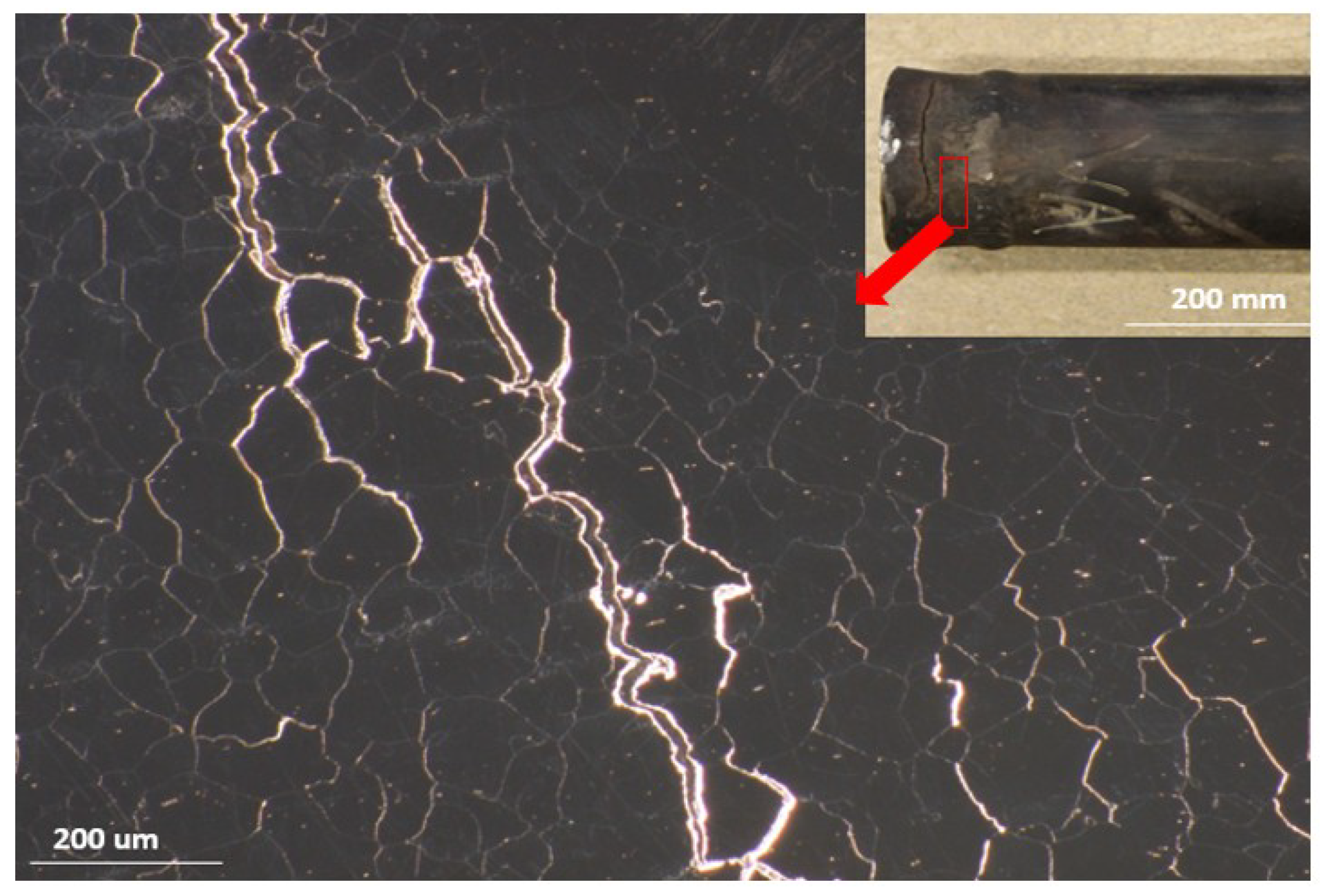
3.1. Visual Examinations

Figure 1 shows an example of a failed tube together with stereomicroscopic image of crack. As can be seen, the crack has propagated circumferentially parallel to the welding line. The crack has propagated in HAZ area in the vicinity of the weld. stereomicroscopic image shows that the crack has propagated alongside grain boundaries. There is no defect in the form of crack or cavities inside the weld, inferring that the weld itself has a perfect quality. In some areas there are some deposits on the surface. Other than these mentioned features, there is hardly any other abnormality in the form of bulging, thinning, or localized deformation in any form. The fact that there is no bulging or localized deformation infers that creep is not a major issue.

3.2. Chemical Analysis

The chemical composition of the alloy was checked with ICPAES to make sure that the chemical composition of the alloy is within the standard range. Table 1 compares the chemical composition of the alloy with the standard values, showing that the alloy has a standard chemical composition.

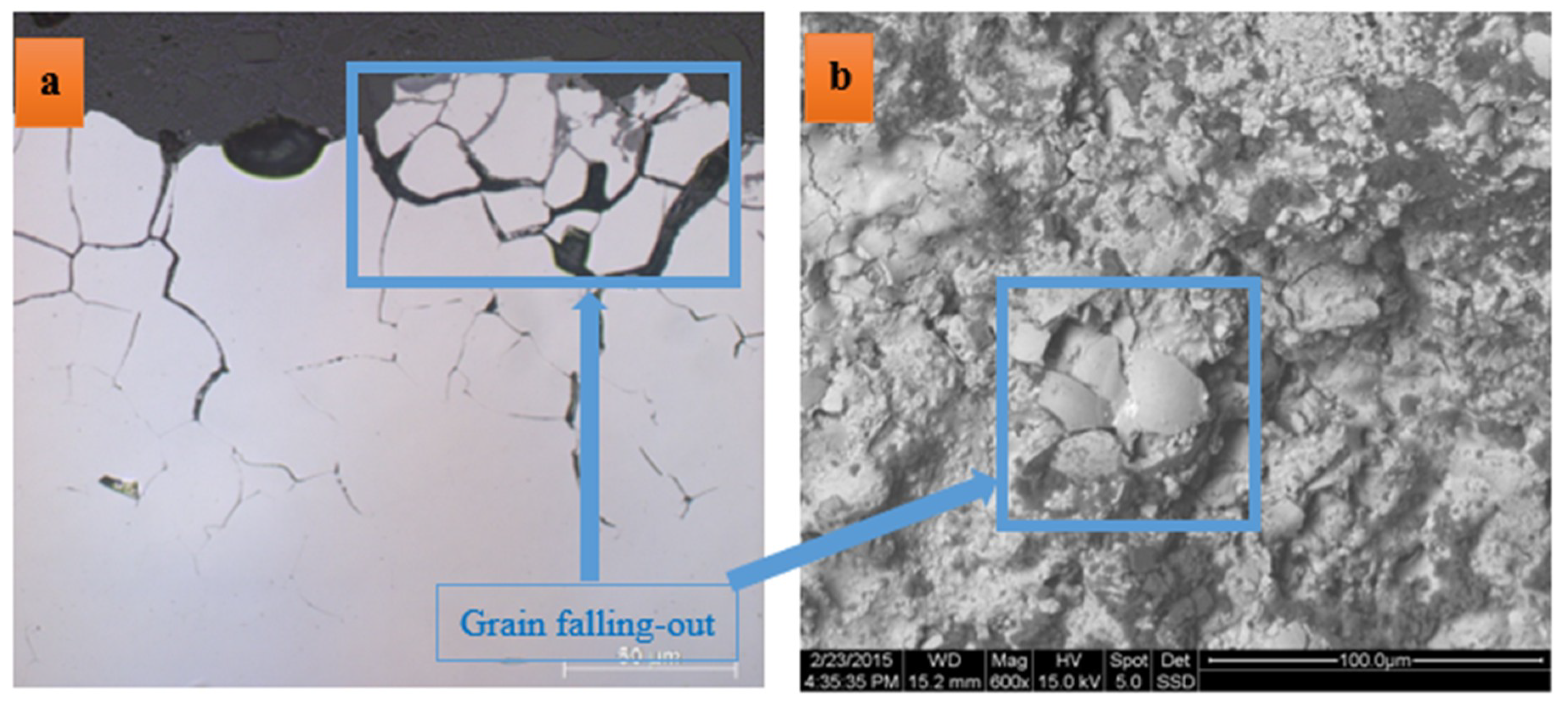
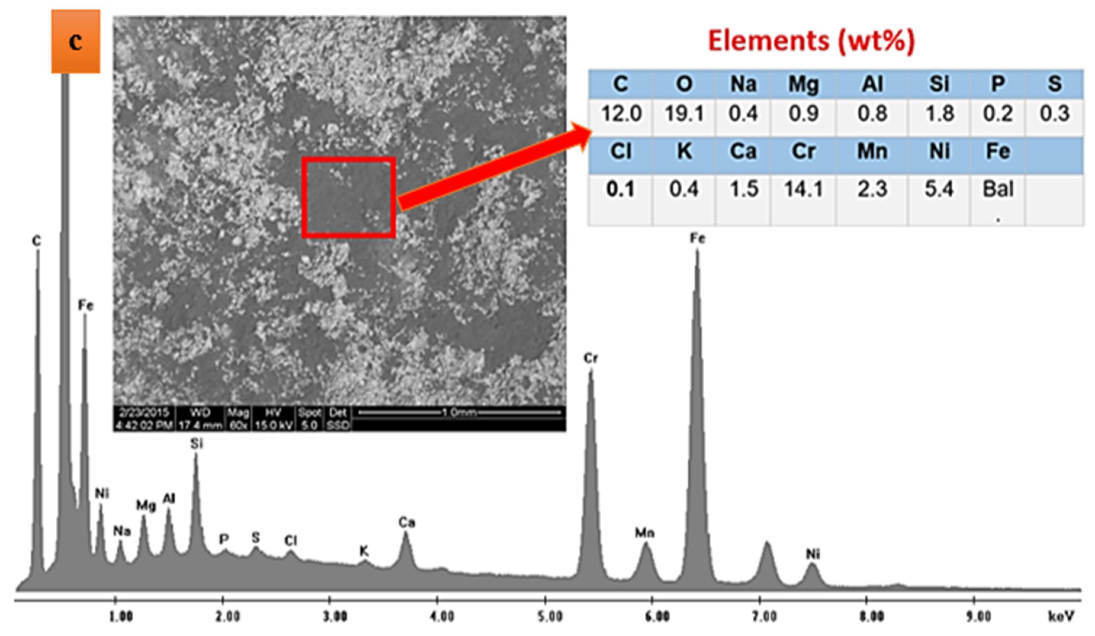
3.3. Analysis of Surface Deposits/Structure

Figure 2 shows grain structure and deposits on the surface of the tube near the damaged area. Two main features are noteworthy to mention. The first noticeable observation is the so-called “grain falling-out” phenomenon (see Figure 2a). It appears that grain boundaries at the surface are heavily oxidized, resulting in the weakening of grain boundary and detachment of a whole grain from the surface. This is also confirmed by the SEM image (Figure 2b). It is also noticeable that some areas on the surface are covered a black deposit. The EDS analysis of these deposits are given in Figure 2c, showing that elements like C, Cl, Mg, Na, and Ca are present in the composition of these deposits. Given that the outer surface of the tube is the fire-side, one can conclude that these deposits are typical fly ashes, coming from the fuel. In this case fly ash corrosion appears to have a significant attribution to the observed failure. Fly ash is a residue generated due to coal combustion and contains fine particles. In this case ash is brought to the system via flue gas. The composition of fly ash depends on the coal and the combustion condition. In most cases, fly ash contains ferric oxide, aluminum oxide, silicon dioxide, and calcium oxide [18]. Fly ash particles are normally collected by filter bags and/or electrostatic filter. Yet, there is a chance that very small residues are not captured by filters. These residues are then precipitated on the outer surface of the tube. Fly ash residues can accelerate surface corrosions. Elements like Ca and Na can diffuse into grain boundaries, resulting in the weakening of grain boundaries and ultimately grain detachment on the surface. Needless to mention that elements like Cl can also severely corrode stainless steels.

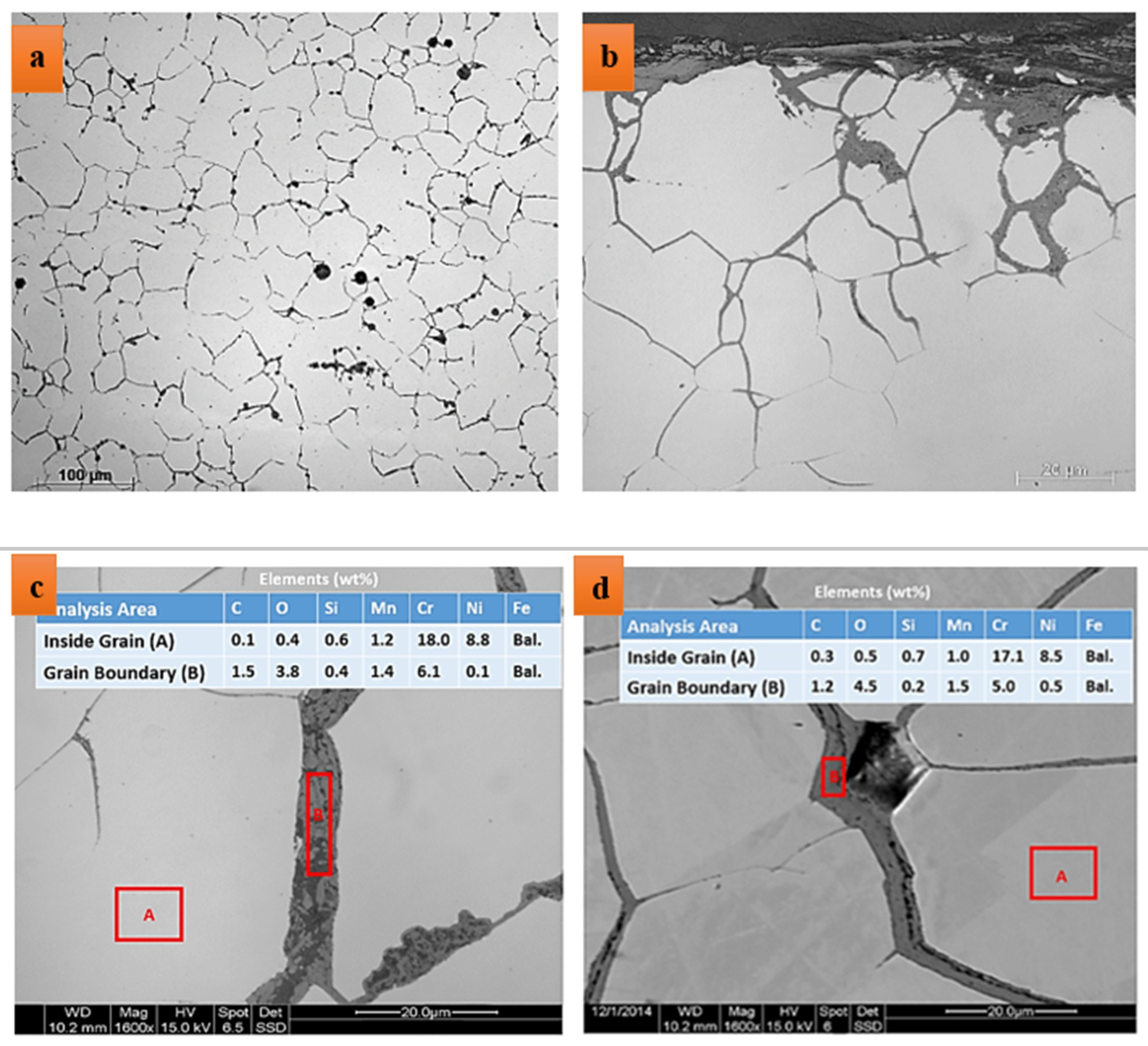
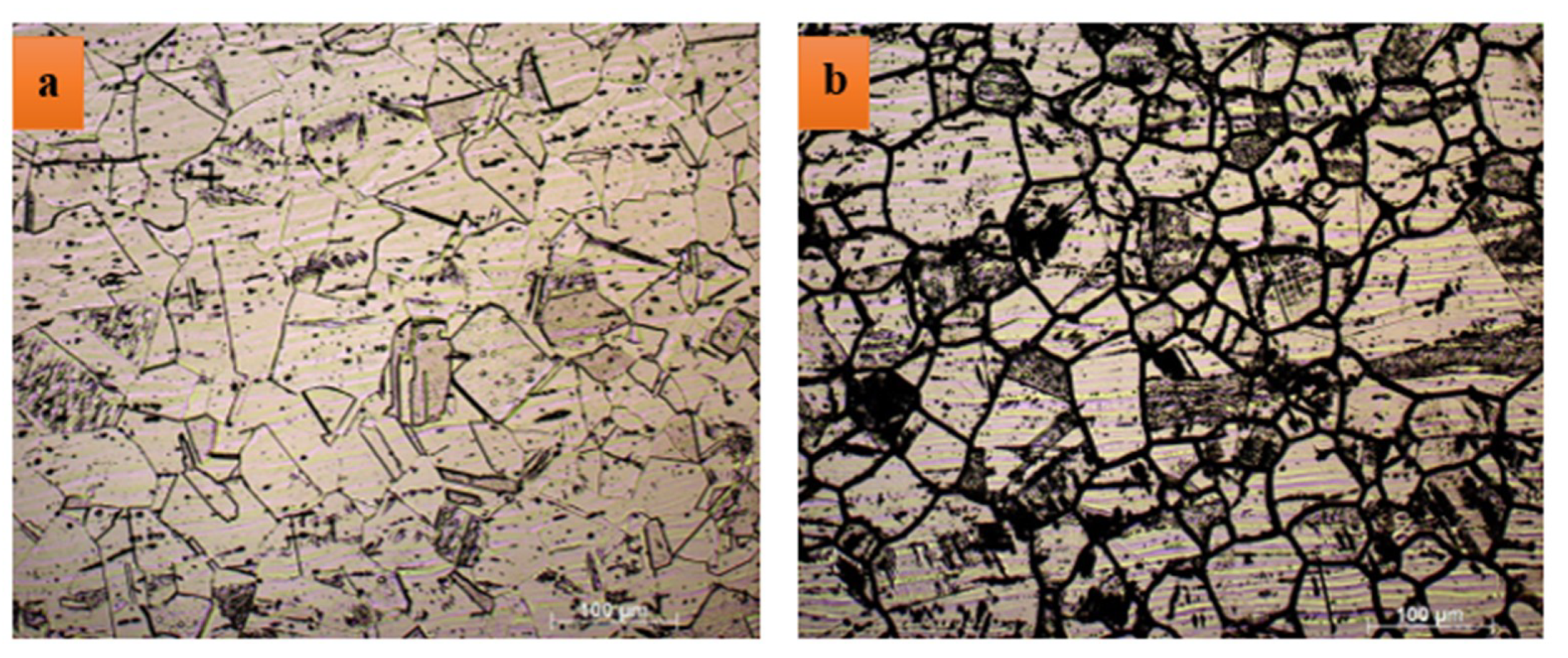
3.4. Microstructure Analysis

Figure 3 shows optical microscope and SEM images of HAZ structure in the as-polished condition. Figure 3a,b show that grain boundaries are mostly covered with a rather thick black phase layer. Figure 3c,d depict that the thickness of the grain boundary phase layer can be as high as 10 µm. The grain boundary phase appears to be rather brittle. This is clearly seen in Figure 3c in which the grain boundary phase is broken. The EDS analyses of grain boundary, given in Figure 3c,d, show that the grain boundary phase is rich in oxygen, carbon, and chromium. It appears that grain boundaries are sensitized and are heavily oxidized. Grain boundary sensitization takes place when chromium carbide precipitates at grain boundaries. Chromium carbide precipitation at grain boundary creates a chromium-depleted zone in the vicinity of sensitized grain boundaries. Given that chromium is the major element when it comes to the corrosion resistance in stainless steels, this narrow chromium-depleted region adjacent to the grain boundaries makes grain boundaries preferential corrosion spots. A continuous network of carbides on grain boundaries and intergranular corrosion makes grain boundaries weak and brittle. Cracks can therefore more easily propagate alongside sensitized grain boundaries. Sensitization of grain boundaries of austenitic stainless steels takes place in temperature range 510 to 780 °C [19]. Any thermal exposure into this temperature range during welding or service could potentially result in the sensitization of grain boundaries in stainless steels. The temperature and time required to cause sensitization and intergranular corrosion depends on the chemistry of the alloy, and more specifically on the carbon content of the alloy. Obviously, the higher the carbon content of the alloy, the higher is the risk of sensitization. For this reason, low carbon stainless steel grades such as AISI 304L and AISI 316L alloys are known to have an excellent resistance against sensitization during welding. In higher alloyed stainless steels such as alloys AISI 904L, grain boundary susceptibility to sensitization is also essentially not a concern [19]. In this case, the observed sensitization has possibly its root in the welding practice. The service temperature is on the lower side of the sensitization temperature range and service exposure has possibly not the major contribution to the sensitization. If sensitization was due to the service exposure, one should have seen sensitization in the base metal as well, which obviously is not the case.

3.5. Assessment of Grain Boundary Sensitization

ASTM A262 [20] is a standard intergranular corrosion assessment method that can be used to evaluate grain boundary sensitization in austenitic stainless steels. The ASTM A262 standard contains five different practices. When stainless steels are exposed to high temperature service for a long time, carbide precipitates on grain boundaries. This creates Cr-depleted areas in the vicinity of grain boundaries, making the alloy susceptible to intergranular corrosion. This standard is a popular assessment method for interganular corrosion susceptibility of stainless steels. This standard contains five different practices, which each being useful for different conditions and materials. Practice A is the simplest method, which is based on the etching of alloys in Oxalic acid. Obtained etch structures can be categorized into the following groups [20]:
  • Step Structure: steps are formed between grains, no ditches at grain boundaries;
  • Dual Structure: Some ditches at grain boundaries in addition to steps; and
  • Ditch Structure: One or more grains completely surrounded by ditches.
The formation of the latter etch structure is an indication of grain boundary sensitization. Figure 4 shows the etch structure of AISI 304 stainless steel in the base metal (Figure 4a) and in the HAZ (Figure 4b). A clear difference is observed between these structures. While the former is a typical step structure, the latter is a clear ditch structure, inferring that HAZ has become severely sensitized during welding and service exposure.

4. Concluding Remarks and Preventive Measures

This paper investigates a failure in convection section tubes of a gas heater unit in a petrochemical plant. Tubes are made of AISI 304 stainless steel. The failure is reported after 5 years of service at working temperature 500 °C. The failure is in the form of circumferential cracks in the vicinity of the weld. The following conclusions can be drawn, based on the obtained results:
  • Damage has initiated at HAZ area in the vicinity of the weld. Cracks have propagated alongside grain boundaries.
  • Grain boundaries in the HAZ area are covered with a rather thick grain boundary phase. Further from the HAZ area in the base metal, there is hardly any indication of such grain boundary phase.
  • Results show that grain boundaries are rich in chromium and are sensitized. Sensitization of grain boundaries is associated with the formation of a narrow Cr-depleted region in the vicinity of grain boundaries. This makes grain boundaries susceptible against corrosion.
  • The test method, proposed in ASTM A262, confirms the susceptibility of grain boundaries in the HAZ area to intergranular attack.
  • Some deposits on the outer surface of tubes are observed. These deposits are rich in C, Cl, Mg, Na, Si, Al, and Ca, indicating that these residues on the surface are fly ashes.
  • Carbon content has a very decisive influence on the susceptibility of grain boundaries. Superior resistance to grain boundary susceptibility can be achieved by reducing the carbon content values less than 0.03 wt%. It is highly recommended to use AISI 304L or other low-carbon stainless steel grades instead of AISI 304.
  • Stabilizing elements like Nb and Ti can also enhance the resistance to sensitization. These elements form stable carbides at high temperature. This way less carbon is available for the formation of chromium carbides at grain boundaries. Commonly used stabilized austenitic stainless steel grades are AISI 321 and AISI 347. Replacement of currently used AISI 304 alloy with stabilized grades is also highly recommended.

Author Contributions

Conceptualization, A.B.; methodology, A.B.; formal analysis, A.B.; investigation, A.B. and P.T.; writing—original draft preparation, A.B.; writing—review and editing, P.T.; visualization, A.B.; supervision, P.T.; project administration, P.T.

Funding

This research received no external funding.

Acknowledgments

Authors would like to thank Delft University of Technology for support in publishing this manuscript.

Conflicts of Interest

The authors declare no conflict of interest.

References

  1. Ghalambaz, M.; Abdollahi, M.; Eslami, A.; Bahrami, A. A case study on failure of AISI 347H stabilized stainless steel pipe in a petrochemical plant. Case Stud. Eng. Fail. Anal. 2017, 9, 52–62. [Google Scholar] [CrossRef]
  2. Mousavi Anijdan, S.H.; Madaah-Hosseini, H.R.; Bahrami, A. Flow stress optimization for 304 stainless steel under cold and warm compression by artificial neural network and genetic algorithm. Mater. Des. 2007, 28, 609–615. [Google Scholar] [CrossRef]
  3. Jafarian, H.; Eivani, A.R. Texture development and microstructure evolution in metastable austenitic steel processed by accumulative roll bonding and subsequent annealing. J. Mater. Sci. 2014, 49, 6570–6578. [Google Scholar] [CrossRef]
  4. Kiani Khouzani, M.; Bahrami, A.; Eslami, A. Metallurgical aspects of failure in a broken femoral HIP prosthesis. Eng. Fail. Anal. 2018, 90, 168–178. [Google Scholar] [CrossRef]
  5. Lavvafi, H. Effects of Laser Machining on Structure and Fatigue of 316LVM Biomedical Wires. Ph.D. Thesis, Case Western Reserve University, Cleveland, OH, USA, 2013. [Google Scholar]
  6. Bahrami, A.; Mousavi Anijdan, S.H.; Taheri, P.; Yazdan Mehr, M. Failure of AISI 304H stainless steel elbows in a heat exchanger. Eng. Fail. Anal. 2018, 90, 397–403. [Google Scholar] [CrossRef]
  7. Lavvafi, H.; Lewandowski, M.E.; Schwam, D.; Lewandowski, J.J. Effects of surface laser treatments on microstructure, tension, and fatigue behavior of AISI 316LVM biomedical wires. Mater. Sci. Eng. A 2017, 688, 101–113. [Google Scholar] [CrossRef]
  8. Natesan, K.; Park, J.H. Fireside and steamside corrosion of alloys for USC plants. Int. J. Hydrog. Energy 2007, 32, 3689–3697. [Google Scholar] [CrossRef]
  9. Ahmad, J.; Rahman, M.M.; Zuhairi, M.H.A. High operating steam pressure and localized overheating of a primary superheater tube. Eng. Fail. Anal. 2012, 26, 344–348. [Google Scholar] [CrossRef]
  10. Ananda Rao, M.; Sankara Narayanan, T.S.N. Failure investigation of a boiler bank tube from a 77 × 2 MW coal based thermal power plant in the northwest region of India. Eng. Fail. Anal. 2012, 26, 325–331. [Google Scholar] [CrossRef]
  11. Almazrouee, A.; Singh, R.K. Role of oxide notching and degraded alloy microstructure in remarkably premature failure of steam generator tubes. Eng. Fail. Anal. 2011, 11, 2288–2295. [Google Scholar] [CrossRef]
  12. Movahedi-Rad, A.; Plasseyed, S.S.; Attarian, M. Failure analysis of superheater tube. Eng. Fail. Anal. 2015, 48, 94–104. [Google Scholar] [CrossRef]
  13. Psyllaki, P.P.; Pantazopoulos, G.; Lefakis, H. Metallurgical evaluation of creep-failed superheater. Eng. Fail. Anal. 2009, 16, 1420–1431. [Google Scholar] [CrossRef]
  14. Khodamorad, S.H.; Alinezhad, N.; Haghshenas Fatmehsari, D.; Ghahtan, K. Stress corrosion cracking in Type.316 plates of a heat exchanger. Case Stud. Eng. Fail. Anal. 2016, 5–6, 59–66. [Google Scholar] [CrossRef]
  15. Corleto, C.R.; Argade, G.R. Failure analysis of dissimilar weld in heat exchanger. Case Stud. Eng. Fail. Anal. 2017, 9, 27–34. [Google Scholar] [CrossRef]
  16. Corte, J.S.; Rebello, J.M.A.; Areiza, M.C.L.; Tavares, S.S.M.; Araujo, M.D.A. Failure analysis of AISI 321 tubes of heat exchanger. Eng. Fail. Anal. 2015, 56, 170–176. [Google Scholar] [CrossRef]
  17. Laurent, M.; Estevez, R.; Fabregue, D.; Ayax, E. Thermomechanical fatigue life prediction of 316L compact heat exchanger. Eng. Fail. Anal. 2016, 68, 138–149. [Google Scholar] [CrossRef]
  18. Fly Ash. Available online: https://www.corrosionpedia.com/definition/1624/fly-ash (accessed on 1 August 2019).
  19. Corrosion: Intergranular Corrosion. Available online: http://www.ssina.com/corrosion/igc.html (accessed on 1 August 2019).
  20. ASTM A262-15. Standard Practices for Detecting Susceptibility to Intergranular Attack in Austenitic Stainless Steels; ASTM International: West Conshohocken, PA, USA, 2015. [Google Scholar]
Figure 1. Macro and stereomicroscopic images of failed specimen.
Metals 09 00969 g001
Figure 2. (a) Optical microscope image of grain falling-out at the surface, (b) SEM image of grain falling-out at the surface, and (c) SEM/energy-dispersive X-ray spectroscopy (EDS) analyses of deposits on the surface.
Metals 09 00969 g002aMetals 09 00969 g002b
Figure 3. Optical microscope images of grain structure in the heat affected zone (HAZ) area of failed specimens; (a,b) an overall view, and (c,d) SEM/EDS analyses of grain boundary phase and inside grains.
Metals 09 00969 g003
Figure 4. Optical microscope images of grain structure in (a) base metal and (b) HAZ area of failed specimen, etched according to standard ASTM A262, Practice A.
Metals 09 00969 g004
Table 1. Chemical composition of the alloy, compared with standard values (in wt%).
AISI 304CSiMnPSCrNiFe
Measured-0.71.400.0110.00618.1010.00Bal.
Standard-0.752.000.0450.03018.00–20.008.00–10.50Bal.

