Article

Friction Drilling of Difficult-to-Machine Materials: Workpiece Microstructural Alterations and Tool Wear

by
Shayan Dehghan
*,
Mohd Idris Shah b. Ismail
*,
Mohd Khairol Anuar b. Mohd Ariffin
and
B. T. Hang Tuah b. Baharudin
Department of Mechanical and Manufacturing Engineering, Faculty of Engineering, Universiti Putra Malaysia, UPM Serdang 43400, Selangor, Malaysia
*
Authors to whom correspondence should be addressed.
Metals 2019, 9(9), 945; https://doi.org/10.3390/met9090945
Submission received: 3 July 2019 / Revised: 17 July 2019 / Accepted: 23 July 2019 / Published: 29 August 2019

Abstract

:
Difficult-to-machine materials are metals that have great toughness, high work-hardening, and low thermal conductivity. Friction drilling of difficult-to-machine materials is a technically challenging task due to the difficulty of friction drilling, leading to excessive tool wear, which adversely affects surface integrity and product performance. In the present study, the microstructural changes of workpieces and tool wear for friction drilling of AISI304, Ti-6Al-4V, and Inconel718 are characterized. It helps to have an in-depth understanding of heat generation mechanics by friction and the mechanism of the friction drilling process. The study contributes to providing an enhanced microstructural characterization of workpiece and tool conditions, which identifies the material behavior and shows how it affects the bushing formation quality and drilling tool performance. The results reveal that the abrasive wear is mostly observed in the conical region of the tool, which has maximum contact with hole-wall. Moreover, the low thermal conductivity of Ti-6Al-4V increases frictional heat generation severely, and reduces product quality and tool life subsequently.

1. Introduction

The fact that the hole-making process is one of the most important operations in industry is undeniable. Friction drilling, as a green, non-traditional, hot-shear machining technology, established by Streppel and Kals [1], is a clean and chipless hole-making process with no cutting fluids that can fulfill the needs of dry machining [2]. However, it has not received any significant attention until last decade, when Miller [3] pioneered the use of this methodology for sheet metal hole-making. During this process the temperature increases, the material structure becomes soft, and as Chow et al. [4] explained, the bushing is formed with a thickness approximately three times larger than the original workpiece thickness. The main contribution of friction drilling is to increase the effectiveness of the thread length, as well as screw coupling, which is used for load clamping in joining applications. Several researchers successfully applied friction drilling in this direction and showed this process is an excellent alternative for hole stamping and nut welding [5], such as for screw coupling [6] and joining of dissimilar materials [7].
The main act in this process is friction leading to the temperature rising in the process, increasing the material ductility and extruding onto both sides of the drilled workpiece. Miller et al. [8] showed that in general, high heat generation changes the material properties and microstructural characteristics. Moreover, Miller et al. [9] found that friction increases erosion and wear dramatically. In other words, material degradation, erosion, and wear have significant effects on the quality and quantity of the process.
The term “difficult-to-machine materials” refers to metals that have unique metallurgical properties, such as great toughness, high work-hardening, and low thermal conductivity. A wide range of applications for difficult-to-machine materials can be found in industry, from automotive to aerospace, and from nuclear to medical. The performance of these materials in machining makes them interesting for researchers [10]. Chow et al. [4] claimed that the attractive advantages of austenitic stainless steel AISI304 are excellent corrosion resistance, a high work-hardening rate, modest thermal conductivity, high temperature oxidation, and good formability. Later, Lee et al. [11] demonstrated that this material usually is accompanied by low productivity, poor surface quality, and short tool life. The wide applications of nickel-based alloy Inconel718 in high temperature conditions with creeping, corrosion, and thermal shock resistance encouraged Yang et al. [12] to bring up its usage in extreme environments, such as aerospace and aircraft industries, gas turbine blades, seals, and jet engines. Shokrani et al. [13] completed a survey on the applications of some difficult-to-machine materials, including austenitic stainless steel AISI304, titanium alloy Ti-6Al-4V, and nickel-based alloy Inconel718 in different fields. In a previous study [14], Zhu et al. considered the application of Ti-6Al-4V, which is readily regarded as a difficult-to-machine material, in the aircraft industry due to the good compromise between mechanical resistance and tenacity, together with its low density and excellent corrosion resistance. Therefore, one might say that the most significant issues addressed in friction drilling of difficult-to-machine materials are product quality and tool life.
The process of friction drilling involves six different stages, as shown in Figure 1. At the beginning, the drilling tool comes into initial contact with the workpiece. Dehghan et al. [15] found out that the peak point of stress also occurs in this step. At the second stage, the workpiece is softened, extruded, and pushed sideward and upward by the drilling tool. Initial bulging on lower surface of the workpiece, leading to the bushing formation, also starts in this step. At stage three, the drilling tool enters the softened workpiece and the conical region is encompassed by molten and softened material. In sequence, the drilling tool pierces the workpiece and the bushing formation begins. At the fourth stage, the drilling tool penetrates inside the workpiece and pushes aside the workpiece material. While the contact interface between tool and workpiece changes from conical to cylindrical regions, the bushing formation is completed. The process of boss formation is completed in stage five, when the drilling tool shoulder pushes the softened back-extruded workpiece material downward. Finally, at the sixth stage, the drilling tool retracts and leaves the completed drilled hole.
The tool wear in friction drilling is categorized into three mechanisms, which are named abrasive wear, adhesive wear, and oxidative wear [9]. The material removal from the drilling tool by hard abrasive phases in the workpiece material is defined by abrasive wear. In friction drilling, abrasive wear occurs as circular grooves in the conical and center regions of the drilling tool. The contact between the two sliding surfaces in the friction drilling process, which generates heating, causes material adhesion from the workpiece and drilling tool to each other. However, most material transfer occurs from the workpiece to the drilling tool. The material adhesion from the workpiece to the drilling tool is named adhesive wear. High heat generation in the workpiece–tool interface increases the potential for oxidization on the drilling tool surface. An oxide layer normally covers the surface of the drilling tool, preventing material adhesion and reducing the adhesive wear tendency.
Lee et al. [11] discovered that insufficient friction drilling performance and excessive tool wear are the most important challenges and obstacles in friction drilling of difficult-to-machine materials. Hence, the improvement of friction drilling performance and increased tool life are two critical issues that should be developed more. To improve friction drilling performance, a comprehensive study on the correlation between associated physical processes of friction drilling and thermo-mechanical behaviors of the process parameters is necessary. Mutalib et al. [16] referred to tool wear as one of the noticeable parameters in all of the manufacturing processes. Since tool wear affects the characteristics and tolerances that are achievable, it is a significant concern that must receive more attention. The excessive tool wear in friction drilling of difficult-to-machine materials shows why a fundamental study on tool condition and microstructural analysis of tool wear for different workpiece materials is needed for further development. Due to the importance of excessive heat generation, which is close to the melting point, and high plastic strain, Eliseev et al. [17] and Lee et al. [11] highlighted the necessity of studying microstructural changes to investigate effects of workpiece material properties, heat generation, and plastic strain. In addition, Ozek and Demir [18,19] showed that microstructural analysis assists in examining the effects of different spindle speeds and feed rates on surface roughness, plastic strain distribution, and cracks on drilled holes.
On the other hand, microstructural analysis is a powerful tool for analyzing different tool wear mechanisms occurring in different regions of the drilling tool. Miller et al. [8] conducted the preliminary study on friction drilling of stainless steel, aluminum, and titanium with a microstructural alterations approach. They stated that the material adhesion to the drilling tool has a wrecking effect on bushing surface quality and tool life. In addition, they found that the generated heat during the friction drilling is dissipated through the drilling tool, workpiece, and surroundings. After that, Miller et al. [9] studied tool wear for AISI1015 and categorized different tool wear mechanisms for the friction drilling process. They also suggested more studies on tool wear and process parameters that may affect the drilling tool performance. Lee et al. [20] applied friction drilling to machining of IN-713LC cast super alloy with different spindle speeds and feed rates. They found that hardness is greater near the hole-wall. They also observed that higher spindle speed causes better roundness. Subsequently, Chow et al. [4] studied friction drilling characteristics of AISI304, such as tool wear, surface roughness, and micro hardness of drilled-holes. In order to obtain higher product quality, they found optimal process parameters for friction drilling of AISI304 with 2 mm thickness. The optimal process parameters were friction angle of 30°, friction contact area ration of 50%, feed rate of 100 mm/min, and spindle speed of 3600 rpm. Lee et al. [11] conducted experiments using uncoated and PVD AlCrN-coated and PVD TiAlN-coated tungsten carbide tools for friction drilling of austenitic stainless steel, where PVD is referred to as physical vapor deposition. Their results showed that coated drilling tools suffered less tool wear than uncoated drilling tool. However, at high spindle speed the drilling tool coating increases heat generation and increases tool wear. Elissev et al. [17] carried out experiments to investigate modification of the AA2024 microstructure produced by friction drilling. They characterized the different zones of materials around the drilled-hole. They also found that frictional heat generation causes grain structure recrystallization.
Due to the wrecking effect of insufficient or extreme heat generation on product and tool life, the microstructure of drilling tools and workpieces is important to analyze. The present work focuses on the microstructural characterization of AISI304, Ti-6Al-4V, and Inconel718 as workpiece materials that are subjected to high temperature and large deformation in the friction drilling process. The tool condition, including wear, degradation, and surface chemistry, for drilling of different workpiece materials is also studied. In addition, a comparative study on microstructural changes and tool conditions for friction drilling of AISI304, Ti-6Al-4V, and Inconel718 is conducted.
The findings of this study are expected to contribute useful knowledge regarding the mechanism of friction drilling for difficult-to-machine materials that have high resistance to corrosion and wear. They can also help to enhance the applicability of the hole-making process in different industries, where the difficult-to-machine materials are widely used.

2. Materials and Methods

As shown in Figure 2, a three-axis computer numerical control (CNC) milling machine (OKUMA MX-45VA, Aichi, Japan) was used in this study. The SEM (HITACHI, S3400N, Tokyo, Japan) used was to observe the microstructure of drilled holes and tools condition. The hole-wall thickness was measured with a micrometer. To analyze chemical composition changes of the drilling tool surface, energy dispersive spectroscopy (EDS) analysis was also conducted. The difficult-to-machine materials chosen for workpieces were AISI304, Ti-6Al-4V, and Inconel718 with thicknesses of 3 mm.
The chemical composition and thermo-mechanical properties of the workpiece materials are shown in Table 1 and Table 2. The drilling tool was made using tungsten carbide in a cobalt matrix. The chemical composition of the drilling tool is also presented in Table 3. Moreover, the geometry and dimension of the drilling tool is shown in Figure 3. The drilling tool used in this study has a shank region of 35 mm, shoulder region of 5 mm, cylindrical region of 10 mm, conical region of 9 mm, center region of 1 mm, shank diameter of 8 mm, shoulder diameter of 14 mm, center angle of 90°, and conical angle of 37°.
To evaluate the relationship between the microstructural changes and mechanical properties of the workpiece material, micro-hardness measurement of the drilled hole was performed on the adjacent area near the drilled hole-wall. The three tested points were near to the hole-wall with different distances, as shown in Figure 4. The micro-hardness measurement was conducted using a micro-hardness machine 401MVD (Wilson and Wolpert, Aachen, Germany) under Vickers scale HV0.1 and 100 gf test load.

3. Results and Discussion

In this section, the obtained results are discussed regarding two factors: workpiece microstructural alterations and wool wear.

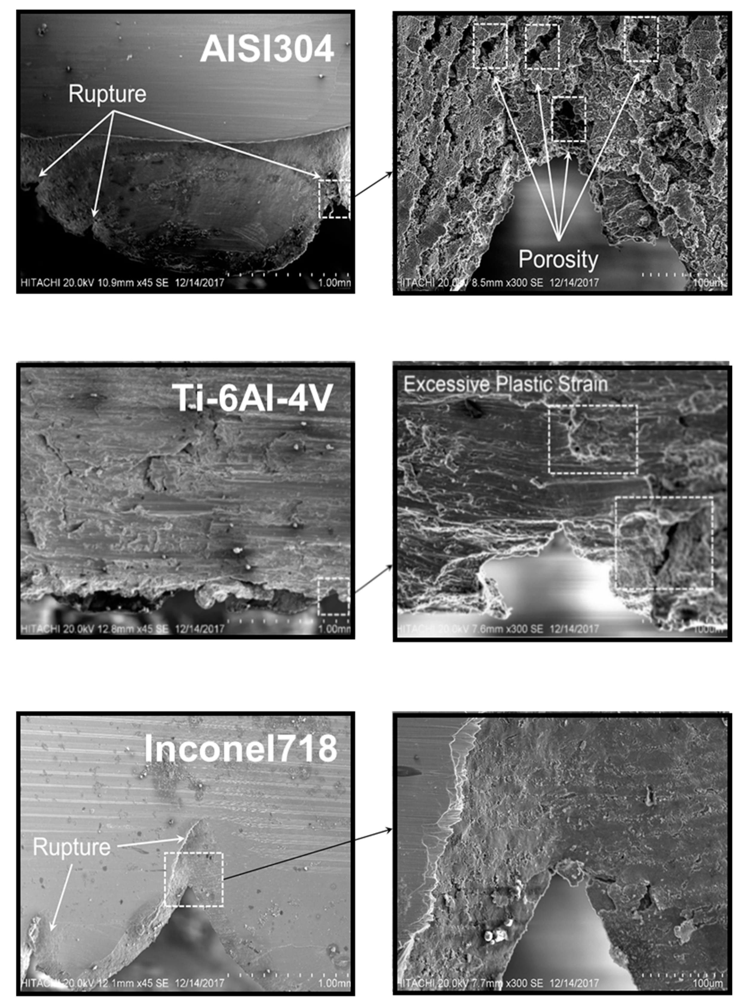
3.1. Workpiece Microstructural Alterations
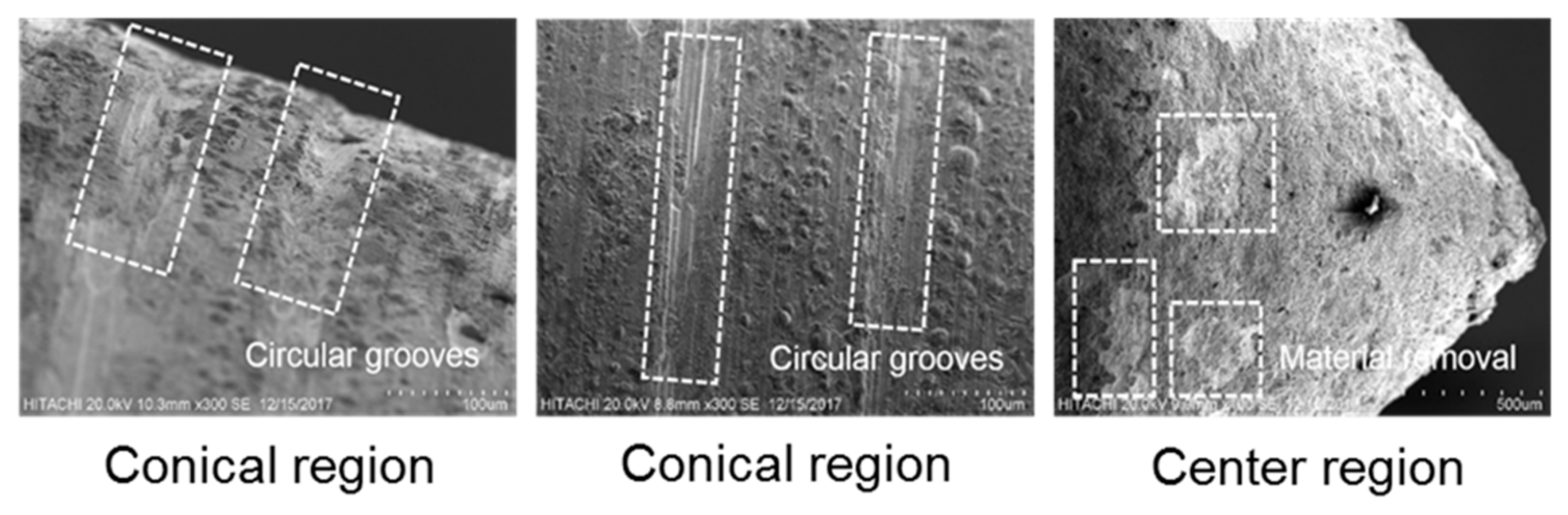
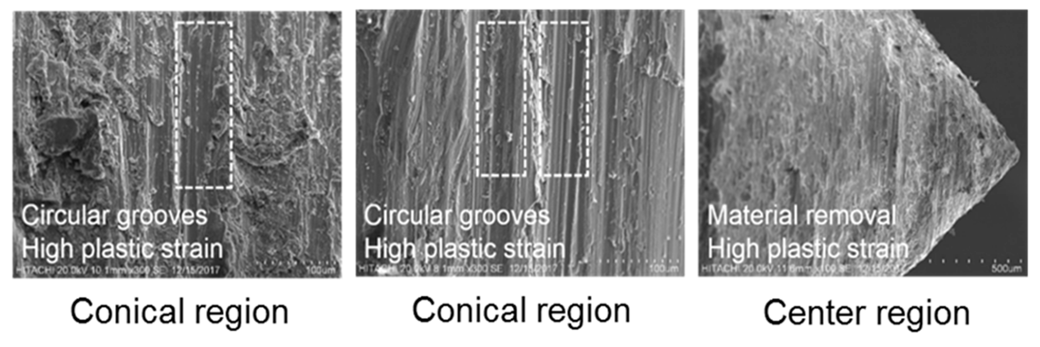
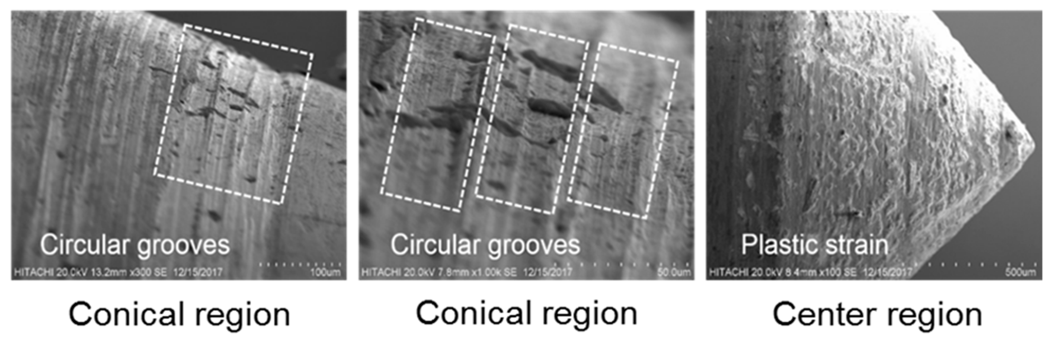
The microstructural analyses of workpieces and the drilling tool are studied in the following. Figure 5 shows high magnified optical views of the workpiece materials’ cross-sections, which were AISI304, Ti-6Al-4V, and Inconel718. Differences in the material displacement are evident, as in the bushing shape, surface quality of the hole-wall, and petal shape.
The friction-drilled hole of AISI304 is relatively uniform in shape and exhibits a smooth bore surface finish. However, some circular grooves on the hole-wall surface, which imply material removal, can be observed. The circular grooves confirm the extreme interaction between the conical region of the drilling tool and the drilled hole-wall. Moreover, the hole-wall thickness is about 2.6 mm.
In contrast, because of the low thermal conductivity of Ti-6Al-4V, which causes ineffective heat generation through the workpiece–tool interface during the friction drilling, the bushing formation is not sufficient. This ineffective heat generation causes material melting, and subsequently bushing formation quality is reduced. As can be observed from Figure 5, due to the excessive heat generation the melted material could not back-extrude and the boss is not formed. This excessive heat generation also has a wrecking effect on petal formation. The low hole-wall surface quality, insufficient hole-wall thickness, and extremely high bushing height implies that the heat generated is not sufficient and the workpiece material is almost melted. The hole-wall thickness of Ti-6Al-4V is smaller than AISI304 and it is about 1.1 mm. This confirms the insufficient heat generation throughout the Ti-6Al-4V drilled hole and the poor product quality. According to titanium’s color, which changes to blue when the material temperature exceeds the melting point, the blue strip on drilled hole and golden color on the lower region of the hole-wall for Ti-6Al-4V is caused by extremely high heat generation in this region of the drilled hole. This causes a chemical reaction between Ti and O elements. Blue and golden colors are the results of Ti2O3 and TiO, respectively.
In comparison with Ti-6Al-4V, the friction-drilled hole of Inconel718 is more uniform in shape than AISI304. High shear strength and high work-hardening of Inconel718 cause sufficient frictional heat generation for friction drilling of this material. The uniform boss and petal formations imply that the heat generation and material softening are more effective and sufficient. The hole-wall thickness is about 1.9 mm. Although the hole-wall thickness is smaller than AISI304, the bushing height is considerably higher than AISI304. Furthermore, the surface quality of the hole-wall for Inconel718 is higher than AISI304 and Ti-6Al-4V.
To analyze the surface quality of the drilled holes, Figure 5 shows close-up views of two zones along the hole-wall, marked by zones (a) and (b) for scanning electron microscopy (SEM). From zone (a) it can be stated that plastic strain on the hole-wall for Ti-6Al-4V is higher than AISI304 and Inconel718. Due to the high heat generation for Ti-6Al-4V, which causes melting of the workpiece material, plastic deformation is severely high. This severely high deformation, which causes surface delamination, confirms the low bushing formation quality for friction drilling of Ti-6Al-4V. In contrast, high strain hardening of Inconel718 results in more sufficient flow material and high bushing formation quality. Moreover, zone (b) presents the surface quality of the hole-wall. It is revealed that the worst quality hole-wall surface with severe surface delamination belongs to Ti-6Al-4V. In contrary, because of the high shear strength of Inconel718, the quality of the hole-wall surface is significantly better than AISI304 and Ti-6Al-4V. Furthermore, the carbide element, which is one of the hard particle elements of Inconel718, has a significant effect on the high quality of the hole-wall surface.
The microstructure views of the petal regions for drilled holes are also shown in Figure 6. As can be observed from the microstructure view of the petal region for AISI304, insufficient heat generation, which results in ineffective material softening, ruptures the workpiece material and causes material removal from the hole-wall surface in the petal region. In other words, since heating is not generated throughout the workpiece sufficiently and workpiece materials do not soften properly, in the third stage, where the drilling tool pierces the softened material, the material is ruptured. Moreover, the existing porosities in the petal region of AISI304 confirms insufficient piercing of the softened material by the drilling tool. Regarding the threading, which is the secondary process after hole-making, and the insufficient hole-wall surface of the petal region of the drilled hole for AISI304, this area of the hole-wall is not effective for clamping and disabling the thread.
Because of the low thermal conductivity of Ti-6Al-4V, which causes severe heat generation along the drilled hole, the petals are not formed properly. A microstructural view of the petal region in Figure 6 shows excessive plastic strain and low hole-wall surface quality of Ti-6Al-4V in the petal region.
In comparison with AISI304, the petal region of Inconel718 is formed properly and material removal from the petal region is negligible. This means the softened workpiece is pierced properly. Some circular grooves, which result from contact between the rotational drilling tool and the hole-wall surface, are also observed on the hole-wall surface. It can be stated that the drilled hole effective area of Inconel718 for threading includes the petal region. This means that clamping of Inconel718 is more efficient than AISI304 and Ti-6Al-4V.
In order to evaluate the heat affected zone hardness of the drilled hole, the measurement is performed on the adjacent area near the drilled hole-wall. In general, the hardness of the adjacent area near the drilled hole is higher than the base material hardness of austenitic stainless steel AISI304, i.e., 226 HV. It can be noted that the closest point to the drilled hole-wall has higher hardness, as displayed in Table 4. A shorter distance from the drilled hole-wall, dramatic increase in temperature, and rapid temperature reduction result in fine grain size and high hardness. Therefore, fine grain size and high hardness are obtained when an excessive temperature gradient occurs near the hole-wall. From the view of heat treatment, an excessive temperature gradient changes the microstructure of the material and makes the grain size finer. However, the hardness of the measured points, which are far from the drilled hole-wall, steadily decreased. The slow temperature reduction makes the grain size coarser and reduces the hardness. Thermal conductivity of Ti-6Al-4V has a significant role in the hardness changes for the friction drilling process. As illustrated in Table 4, the lower hardness occurred at the closer region to the hole-wall. With the distance from the hole-wall, the hardness is increased gradually. After penetration and drilling tool retraction from the drilled hole, the temperature of the closer areas to the hole edge is increased. However, the temperature does not rise significantly when the distance of the drilled hole edge increases. In other words, due to the low thermal conductivity of Ti-6Al-4V (k = 5.8 W/mK), i.e., being almost three times lower than stainless steel AISI304 (k = 16.2 W/mK), the heating phase takes more time. Therefore, the higher heat generation needs a longer cooling time, and the longer cooling time prolongs the needed time for growth of the grain size. Thus, the hardness is increased gradually when the tested points are away from the drilled hole edge. As can be observed, for Inconel718, the region closer to the hole edge has lower hardness. This can be attributed to the low thermal conductivity of Inconel718 (k = 11.4 W/mK), which is lower than AISI304 (k = 16.2 W/mK), as a result of slow heating and cooling of the hole edge. The low thermal conductivity of Inconel718 causes the cooling to take a long time, and subsequently large grains are formed along the hole edge, resulting in low hardness.

3.2. Tool Wear

Figure 7, Figure 8, and Figure 9 display the drilling tools, which drilled one hole for each workpiece material (AISI304, Ti-6Al-4V, and Inconel718) in the center and conical regions. Circular grooves in the conical region imply material removal from the drilling tool and abrasive wear. It also confirms maximum interaction of the drilling tool with the hole-wall in the conical region. The material from center region of the drilling tool is also removed, but not the same as for the circular grooves in the conical region. In the first stage, during initial contact between the tool and workpiece, heat generation and material softening are still insufficient. Therefore, stress and required thrust force for penetration are extremely high.
Due to the severe heat generation during the friction drilling of Ti-6Al-4V caused by low thermal conductivity of Ti-6Al-4V, plastic strain on the drilling tool is much greater than tools that drilled AISI304 and Inconel718. On the other hand, the carbide element that exists in Inconel718 causes more severe material removal and circular grooves on the drilling tool than AISI304.
The tool profiles of a new tool and tools after drilling of AISI304, Ti-6Al-4V, and Inconel718 are compared in Figure 10. The material removal from tools and material adhesion on tools represent the abrasive wear and adhesive wear on conical and center regions. Although wear on the tools that drilled AISI304 and Inconel718 is in the form of material removal, circular grooves on the tool that drilled AISI304 are worse than Inconel718. In contrast, wear on the tool hat drilled Ti-6Al-4V is in the form of material adhesion. It is worth mentioning that the wear on the tools hat drilled AISI304, Ti-6Al-4V, and Inconel718 are about 0.85%, 3.84%, and 1.26%, respectively.
Figure 11 shows energy dispersive spectroscopy (EDS) analysis of the drilling tool before drilling. A large amount of Si is observed on the drilling tool surface. This is attributed to the coating of the drilling tool surface with SiO2.
Figure 12, Figure 13, and Figure 14 display SEM mapping and EDS analysis of center and conical regions for drilling tools that drill different workpiece materials (AISI304, Ti-6Al-4V, and Inconel718). As observed in Figure 11, the Fe element, which is presented on the drilling tool surface that drills AISI304, indicates the transfer of this element from the workpiece to the drilling tool. This material transfer confirms the adhesive wear. Moreover, the presence of the O element on the surface of the drilling tool is evidence of oxidization in the center and conical regions of the drilling tool, where the heating was generated.
The SEM mapping and EDS analysis of the drilling tool that drilled Ti-6Al-4V is indicated in Figure 13. The large amounts of Ti and Al elements confirm transfer of material from the workpiece to the drilling tool and adhesive wear. In addition, the larger amount of Si element in the center region compared to the conical region shows that interaction between the hole-wall surface and the drilling tool in the conical region is more severe than the center region, and material removal from the conical region is more severe than the center region. In comparison with Figure 12, it is also indicates that adhesive wear on the drilling tool that drills Ti-6Al-4V is more severe than the drilling tool that drills AISI304. This is related to the lower thermal conductivity of Ti-6A-4V than AISI304, which causes excessive heat generation in the workpiece–tool interface and material adhesion to the drilling tool surface. Furthermore, the presence of the O element on the drilling tool surface confirms the oxidization and oxidative wear. As can be seen, due to the higher adhesive wear on the drilling tool that drills Ti-6Al-4V compared with the drilling tool that drills AISI304, oxidative wear on the drilling tool that drills Ti-6Al-4V is less than the drilling tool that drills AISI304.
As displayed in Figure 14, from the SEM mapping and EDS analysis of the drilling tool that drills Inconel718, it is revealed that the oxidative wear is greater than other drilling tools. However, the presence of Ni and Fe elements confirms the adhesive wear. It can be stated that the maximum adhesive wear is observed on the drilling tool that drills Ti-6Al-4V. This means that Ti-6Al-4V elements can easily transfer to the drilling tool surface. On the other hand, due to the lower tendency of Inconel718 elements to transfer to the drilling tool surface, the maximum oxidative wear is found on the drilling tool that drills Inconel718.

4. Conclusions

In this paper, an enhanced microstructural characterization of workpiece and tool conditions for friction drilling of difficult-to-machine materials is provided. The microstructural changes of AISI304, Ti-6Al-4V, and Inconel718 and tool wear are analyzed and compared. Details of microstructural alterations of workpiece and tool wear help to identify the material behavior and how it affects the bushing formation quality and drilling tool performance for friction drilling of difficult-to-machine materials. The experimental results show that bushing shape, surface quality of the hole-wall, and petal formation of Inconel718 and AISI304 are significantly better than Ti-6Al-4V. The low thermal conductivity of Ti-6Al-4V and high shear strength and work-hardening of Inconel718 have the main effects on product quality and tool wear. Moreover, it is found that the abrasive wear is mostly observed in the conical region of the drilling tool that has maximum contact with the hole-wall. The microstructural analysis and surface chemistry of the drilling tool show that the tool wear on the drilling tool that is used for friction drilling of Ti-6Al-4V is more severe than other tools. The abrasive wear on the tool that drilled AISI304 is in the form of material removal and the abrasive wear on the tool that drilled Ti-6Al-4V is in the form of tool destruction. Moreover, the abrasive wear on the tool that drilled Inconel718 is in the form of circular grooves. A higher amount of adhesive wear occurs from Ti-6Al-4V to the drilling tool and a lower amount of adhesive wear occurs from Inconel718 to the drilling tool. The maximum oxidative wear is also mostly observed on the drilling tool that drilled Inconel718.

Author Contributions

Conceptualization, S.D.; methodology, S.D.; M.I.S.b.I., and M.K.A.b.M.A.; formal analysis, S.D.; investigation, S.D.; resources, S.D. and M.I.S.b.I.; data curation, S.D.; M.I.S.b.I., and B.T.H.T.b.B.; writing—original draft preparation, S.D.; writing—review and editing, S.D., M.I.S.b.I., M.K.A.b.M.A., and B.T.H.T.b.B.

Acknowledgments

This research was funded by Fundamental Research Grant Scheme (FRGS/1/2015/TK03/UPM/02/2) under the Ministry of Higher Education of Malaysia (MOHE), and Putra Grant (GP-IPS/2015/9452600) under Universiti Putra Malaysia (UPM).

Conflicts of Interest

The authors declare no conflict of interest.

References

  1. Streppel, A.; Kals, H. Flowdrilling: A Preliminary Analysis of a New Bush-Making Operation. CIRP Ann. 1983, 32, 167–171. [Google Scholar] [CrossRef]
  2. Pereira, O.; Urbikaín, G.; Rodríguez, A.; Calleja, A.; Ayesta, I. Process performance and life cycle assessment of friction drilling on dual-phase steel. J. Clean. Prod. 2019, 213, 1147–1156. [Google Scholar] [CrossRef]
  3. Miller, S.F. Experimental Analysis and Numerical Modeling of the Friction Drilling Process. Ph.D. Thesis, University of Michigan, Ann Arbor, MI, USA, 2006. [Google Scholar]
  4. Chow, H.M.; Lee, S.M.; Yang, L.D. Machining characteristic study of friction drilling on AISI 304 stainless steel. J. Mater. Process. Technol. 2008, 207, 180–186. [Google Scholar] [CrossRef]
  5. Elkobbah, K. Thermal friction drilling: A Review. In Proceedings of the 15th International Conference on Aerospace Sciences & Aviation Technology, Cairo, Egypt, 28–30 May 2013. [Google Scholar]
  6. Skovron, J.D.; Prasad, R.R.; Ulutan, D.; Mears, L.; Detwiler, D.; Paolini, D.; Baeumler, B.; Claus, L. Effect of Thermal Assistance on the Joint Quality of Al6063-T5A During Flow Drill Screwdriving. J. Manuf. Sci. Eng. 2015, 137, 051019. [Google Scholar] [CrossRef]
  7. Urbikain, G.; Perez, J.M.; De Lacalle, L.N.L.; Andueza, A.; Pelayo, G.U. Combination of friction drilling and form tapping processes on dissimilar materials for making nutless joints. Proc. Inst. Mech. Eng. Part. B J. Eng. Manuf. 2016, 232, 1007–1020. [Google Scholar] [CrossRef]
  8. Miller, S.F.; Blau, P.J.; Shih, A.J. Microstructural Alterations Associated with Friction Drilling of Steel, Aluminum, and Titanium. J. Mater. Eng. Perform. 2005, 14, 647–653. [Google Scholar] [CrossRef]
  9. Miller, S.F.; Blau, P.J.; Shih, A.J. Tool wear in friction drilling. Int. J. Mach. Tools Manuf. 2007, 47, 1636–1645. [Google Scholar] [CrossRef]
  10. Dehghan, S.; Ismail, M.I.S.; Ariffin, M.K.A.; Baharudin, B.T.H.T. Experimental investigation on friction drilling of titanium alloy. Eng. Solid Mech. 2018, 6, 135–142. [Google Scholar] [CrossRef]
  11. Lee, S.M.; Chow, H.M.; Huang, F.Y.; Yan, B.H. Friction drilling of austenitic stainless steel by uncoated and PVD AlCrN- and TiAlN-coated tungsten carbide tools. Int. J. Mach. Tools Manuf. 2009, 49, 81–88. [Google Scholar] [CrossRef]
  12. Yang, L.D.; Ku, W.L.; Chow, H.M.; Wang, D.A.; Lin, Y.C. Mar-M247, Haynes-230 and Inconel-718 Study of Machining Characteristics for Ni-Based Superalloys on Friction Drilling. Adv. Mater. Res. 2012, 459, 632–637. [Google Scholar] [CrossRef]
  13. Shokrani, A.; Dhokia, V.; Newman, S.; Newman, S. Environmentally conscious machining of difficult-to-machine materials with regard to cutting fluids. Int. J. Mach. Tools Manuf. 2012, 57, 83–101. [Google Scholar] [CrossRef] [Green Version]
  14. Zhu, Z.; Sui, S.; Sun, J.; Li, J. Investigation on performance characteristics in drilling of Ti6Al4V alloy. Int. J. Adv. Manuf. Technol. 2017, 93, 651–660. [Google Scholar] [CrossRef]
  15. Dehghan, S.; Ismail, M.I.S.; Ariffin, M.K.A.; Baharudin, B.T.H.T.; Sulaiman, S.; Ismail, M.I.S. Numerical simulation on friction drilling of aluminum alloy. Materwiss Werksttech 2017, 48, 241–248. [Google Scholar] [CrossRef]
  16. Mutalib, M.Z.A.; Ismail, M.I.S.; Jalil, N.A.A.; As’arry, A. Characterization of tool wear in friction drilling. J. Tribol. 2018, 17, 93–103. [Google Scholar]
  17. Eliseev, A.; Fortuna, S.; Kolubaev, E.; Kalashnikova, T. Microstructure modification of 2024 aluminum alloy produced by friction drilling. Mater. Sci. Eng. A 2017, 691, 121–125. [Google Scholar] [CrossRef]
  18. Özek, C.; Demir, Z. Investigate the effect of tool conical angle on the bushing height, wall thickness and forming in friction drilling of A7075-T651 aluminum alloy. Usak Univ. J. Mater. Sci. 2013, 2, 61–74. [Google Scholar]
  19. Ku, W.L.; Hung, C.L.; Lee, S.M.; Chow, H.M. Optimization in thermal friction drilling for SUS 304 stainless steel. Int. J. Adv. Manuf. Technol. 2011, 53, 935–944. [Google Scholar] [CrossRef]
  20. Lee, S.M.; Chow, H.M.; Yan, B.H. Friction Drilling of IN-713LC Cast Superalloy. Mater. Manuf. Process. 2007, 22, 893–897. [Google Scholar] [CrossRef]
Figure 1. Process stages involved in friction drilling.
Metals 09 00945 g001
Figure 2. Experimental setup of friction drilling process.
Metals 09 00945 g002
Figure 3. Key dimensions of the friction drilling tool.
Metals 09 00945 g003
Figure 4. Schematic of selected points to measure hardness.
Metals 09 00945 g004
Figure 5. Cross-section and close-up view of zones (a) and (b) of friction drilled-holes.
Metals 09 00945 g005
Figure 6. Microstructure view in the petal regions of drilled-holes.
Metals 09 00945 g006
Figure 7. Microstructural views of drilling tool at conical and center regions for friction drilling of AISI304.
Metals 09 00945 g007
Figure 8. Microstructural views of the drilling tool in conical and center regions for friction drilling of Ti-6Al-4V.
Metals 09 00945 g008
Figure 9. Microstructural views of the drilling tool in conical and center regions for friction drilling of Inconel718.
Metals 09 00945 g009
Figure 10. Profiles of new tools and after drilling of AISI304, Ti-6Al-4V, and Inconel718.
Metals 09 00945 g010
Figure 11. EDS analysis of new drilling tool surface.
Metals 09 00945 g011
Figure 12. Scanning electron microscope (SEM) mapping of the drilling tool in the center and conical regions for friction drilling of AISI304.
Metals 09 00945 g012
Figure 13. Scanning electron microscope (SEM) mapping of the drilling tool in the center and conical regions for friction drilling of Ti-6Al-4V.
Metals 09 00945 g013
Figure 14. SEM mapping of the drilling tool in the center and conical regions for friction drilling of Inconel718.
Metals 09 00945 g014
Table 1. Chemical compositions of AISI304, Ti-6Al-4V, and Inconel718 (wt.%).
MaterialsCrFeMnNiSiAlTiVCoMoNb
AISI30418~2066~74280~10.51------
Ti-6Al-4V-----6904---
Inconel71817~2117-50~55----12.8~3.34.8~5.5
Table 2. Thermo-mechanical properties of AISI304, Ti-6Al-4V, and Inconel718.
Mechanical and Thermal PropertiesAISI304Ti-6Al-4VInconel718
Ultimate tensile strength, MPa 5059501375
Yield strength, MPa 2158801100
Young’s modulus, GPa 198123298
Thermal conductivity, W m K 16.25.811.4
Melting point, °C1400~14551604~16601260~1336
Table 3. Chemical composition of tungsten carbide (wt.%).
MaterialsCrNiCSiTiFeTaWCo
WC (Tungsten carbide)0.100.139~120.151.961.935.0257~677~12
Table 4. Hardness of selected points for different materials.
Workpiece-MaterialsTested PointsHardness, HV
AISI3041st point239
2nd point233
3rd point228
Ti-6Al-4V1st point379
2nd point396
3rd point410
Inconel7181st point283
2nd point341
3rd point459

