Article

Influence of Nickel Powders on Corrosion Resistance of Cold Sprayed Coatings on Al7075 Substrate

1
Institute of Chemistry, Jan Kochanowski University in Kielce, Swietokrzyska 15G, PL-25406 Kielce, Poland
2
Laser Processing Research Centre, University of Technology, 1000-lecia Panstwa Polskiego 7, PL-25314 Kielce, Poland
3
Institute of Metallurgy and Materials Science, Polish Academy of Sciences, Reymonta 25, PL-30059 Krakow, Poland
*
Author to whom correspondence should be addressed.
Metals 2019, 9(8), 890; https://doi.org/10.3390/met9080890
Submission received: 29 June 2019 / Revised: 7 August 2019 / Accepted: 10 August 2019 / Published: 15 August 2019

Abstract

:
The influence of the size and structure of nickel powder grains on the corrosion resistance of nickel coatings on an Al7075 substrate in an acidic chloride solution was investigated. The Ni coating was produced by the cold spraying (CS) method. The surface and microstructure of specimens were observed by a scanning electron microscope (SEM). The corrosion test of the materials was carried out by using the electrochemical method. It has been found that the size of Ni powders has a significant effect on the corrosion resistance of nickel coatings. The porosity of nickel coatings on the Al7075 alloy increases with the increasing size of nickel powders. The corrosion rate of nickel coatings in the chloride environment decreases as the diameter of the nickel powders decreases. On the other hand, the highest corrosion resistance of nickel coatings was obtained using the Ni powders of the irregular spherical or dendritic structure. Moreover, the large particles of nickel powder cause strong residual stress (compared to small grains) in the depth of the nickel coatings.

1. Introduction

Cold spraying (CS), an emerging coating technique, has been developed to deposit high-quality metallic coatings. In this process, high-pressure gas is introduced into a de-Laval type nozzle and produces a high-speed gas flow, and then spray particles are fed axially into the gas flow and accelerated to a high velocity ranging between 300 and 1200 m s−1. They are then deposited through an intensive plastic deformation upon impact on a substrate in a solid-state at a temperature well below the melting point of the spray material, i.e., <600 °C. The particle velocity at which the deposition takes place is known as the critical velocity, which is a function of the yield strength of the powder material. Only the particles that have a velocity higher than this critical value are deposited to form a coating on the substrate [1]. Another type of deposition behavior is often observed for splats deposited at velocities significantly higher than the critical velocity. The deformation takes place not only in the cold sprayed materials but also in the substrate material. The intimate contact between the splat and the substrate contributes to a more continuous, void or oxide free, bond between two interfaces and even stronger splat adhesion, which significantly improves the corrosion resistance of materials. Therefore, CS is an optimal technique to produce dense metallic coatings for corrosion protection. However, the denseness of the coating is indeed required when corrosion resistance is provided by a coating nobler than its substrate. It is worth adding that it is recommended to clean the surface of the substrate to achieve a high standard of the coating. Several reports on the deposition of many metals such as copper and its alloys [2,3,4], titanium and its alloys [5,6,7], tantalum [8,9,10], nickel and its alloys [11,12], and other materials are noteworthy. Moreover, nickel is known as a corrosion resistant metal in many aggressive media. It corrodes at a significant rate in the presence of mineral acids or in a neutral medium. The corrosion resistance of Ni coatings increases with a decrease in porosity. Fully dense coating structures could be deposited by the cold spraying method. The powder characteristics have a significant impact on the tightness, density, and deposition behavior. During CS deposition, smaller sized powders achieve higher speeds and, thus, a more homogeneous coating structure is obtained. However, the feedstock of sizes smaller than 10 µm is not practical because it gives a subdued flow ability and is difficult to form a deposit fluently [13]. The CS method is also used to make composites, such as nickel-copper [14]. Ni-Cu coatings exhibit high corrosion resistance in alkaline and acidic environments [15,16]. Therefore, the Ni-Cu alloy could be used in salty marine environments as it is resistant to the pitting corrosion of equipment [17]. In work [18], the CS method was used to deposit NiCr, NiCrTiC, and NiCrTiCRe powders on the steel of a boiler successfully. It turned out that all the examined coatings successfully decreased the erosion-corrosion rate of the substrate in the boiler environment. The mechanical properties of CS coatings are significantly influenced by the structure of the coating and the bonding of particles of the coating material to the substrate. It is known that the adhesion between the coating and the substrate depends on the type of metal powder and the process conditions such as particle velocity and process temperature. The CS method was used to prepare the WC-Co coatings [19]. It turned out that there is no degradation of WC-Co powder during the cold spraying process, and a well-bonded and phase pure WC coating is produced. CS coatings were produced by spraying WC-25Co powders onto Al7075-T6 and low-carbon steel substrates [20]. The mechanical properties of coatings on both substrates were found to be very similar to those obtained by the high-velocity oxy-fuel (HVOF) method. Moreover, the gas pressure and gas temperature are two critical factors for obtaining high-quality coatings [21]. A number of investigations on the characteristics of mechanical and tribological properties of cold-sprayed titanium coatings on commercial Ti-6Al-4V substrates have been performed [22,23,24,25]. It turned out that the mechanical properties of each coating mainly depend on its microstructure and thicknesses. On the other hand, the powder characteristics (mainly the grain size) have a significant impact on the tightness, density, and adhesion of the coating on the substrate. Ajdelsztajn et al. [26] reported that Ni powders of irregular shape are more suitable to obtain a dense coating than spherical ones, because they acquire much higher impact velocity. Góral et al. [27] showed that it is possible to produce dense coatings using both dendritic and irregular spherical Ni powders. However, the coating sprayed with dendritic powder exhibited better mechanical properties and significantly lower surface roughness in comparison with the deposit sprayed with spheroidal particles. Aluminum and its alloys (e.g., Al7075) are widely used for the production of light and mechanically tough products, mainly in aviation [28,29]. Unfortunately, these materials easily lose their strength properties as a result of corrosion, chemical, and electrochemical processes. One of the methods to increase the corrosion resistance of these materials is to use nickel protective coatings because Ni has advantageous properties, such as recoverability, good thermal conductivity, high hardness, good oxidation stability, and high mechanical strength.
In the present study, the influence of the size and structure of nickel powder grains on the corrosion resistance of Ni cold-sprayed coatings on the Al7075 alloy was examined. The corrosion test of materials was carried out by using the electrochemical method. The corrosive environment was an acidic chloride solution. The surface morphology of the materials was investigated by a scanning electron microscope (SEM). In addition, other assistive techniques were used to broaden the scope of the research. The results are used to determine the corrosion mechanism of tested materials. Experimental studies have been performed on the distribution of residual stresses generated during the CS process.

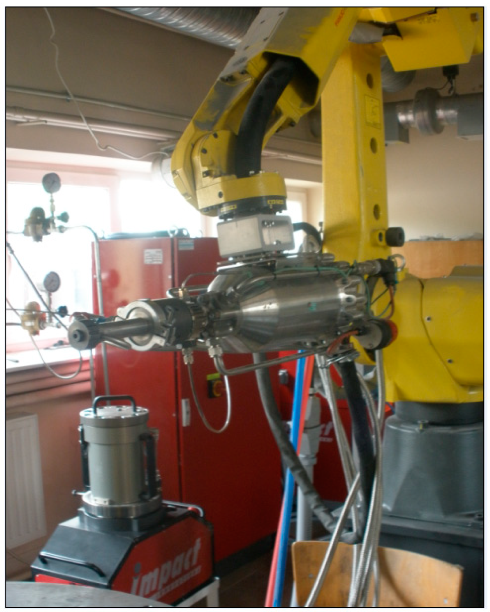
2. Materials and Methods

Nickel coatings were sprayed by means of the cold spray system Impact Innovations 5/8 equipped with the Fanuc M-20iA robot (Funac Robotics Ltd., Oshino, Japan) which is shown in Figure 1.
Nickel powders of grain size ranging from 15 μm to 75 μm were used in the cold spraying process, Table 1. The nickel content in the feedstock of powders ranged from 99.7 to 99.8% Ni.
The following parameters were used for the production of the nickel coatings: nitrogen pressure—30 bar, nitrogen preheating temperature—800 °C, spraying distance—60 mm, traverse speed—40 mm/s, the step size between 10 passes was 2 mm, number of layers—4. The Ni coatings were deposited on the Al7075 alloy. The chemical composition of the Al7075 alloy is as follows (wt%): 5.6% Zn, 2.5% Mg, 1.6% Cu, 0.22% Cr, <0.50% are admixtures (i.e., Mn, Fe, and Si), the rest is aluminum. The surface of Al7075 substrates were prepared by blasting with the corundum of size 30 (600 μm–710 μm). The specimen sizes were 30 × 10 × 5 mm3. The thicknesses of the sprayed coatings were in the range from 1700 μm to 1780 μm.
The surface and microstructure of the specimens were observed by using a scanning electron microscope (SEM) Joel (Tokyo, Japan), type JSM-5400. The accelerating voltage of the SEM was 20 kV. The chemical composition for the corroded surface was also measured by an energy-dispersive spectrometer (EDS).
The X-ray diffraction was used to characterize the phase composition of the powders (Philips PW1710, Malvern, UK) and cold-sprayed coatings (D8 Bruker Discover, Malvern, UK) using Co radiation (wavelength was 0.17889 nm). Before each measurement, the coatings were mechanically polished to remove the roughness on the surface. The crystallite size of the deposits was evaluated by the peak broadening analysis of the X-ray diffraction patterns using the Scherrer equation: d = K λ β cos θ , where d is the average crystallite size, K is the Scherrer constant (assumed as 0.9), λ is the incident radiation wavelength, β is the corrected peak width at half-maximum intensity, θ is the angular position.
The grain size distributions of the nickel powders was determined by a laser diffraction particle size analyzer Mastersizer 3000, MALVERN Instruments (Malvern, UK).

2.1. Corrosion Test

All electrochemical measurements (corrosion tests) were carried out by using the potentiostat/galvanostat PGSTAT 128N, AutoLab (Amsterdam, The Netherlands) piloted by the NOVA 1.7 software. The electrochemical experiments were carried out in a conventional three-electrode cell.
The working electrode (stationary) was made of an Al7075 alloy without or with a nickel coating which was applied to the substrate by the CS method using nickel powders of different gradings of grains (Table 1). The geometric surface area of the working electrode was 1 cm2. The working electrode was in contact with the electrolyte only from the Ni coating side. The remaining electrode surface was isolated from the electrolyte solution with a non-conductive epoxy coating. Before each measurement, the surface of the electrode was washed with bidistilled water, ultrasonically, and dried at room temperature. Subsequently, the working electrode was immediately immersed in the test solution until a steady state was reached. The experiment was started after a 30-min immersion of the electrode in the corrosive solution.
The saturated calomel electrode (SCE) was used as the reference, and the counter electrode (9 cm2) was made from platinum foil (99.9% Pt).
The corrosive environment (supporting electrolyte) was obtained by mixing sodium chloride and hydrochloric acid so the concentration of Cl ion was 1.2 M. The pH value was 1.5. The electrolyte was not deoxygenated.
Open circuit potential (EOCP) measurements was performed in a two-electrode cell by the immersion test where the specimen (working electrode) was suspended in the corrosive environment. Moreover, OCP potential values were registered over 300 h.
The potentiodynamic polarization (LSV) curves were recorded. All measurements were carried out under the potential range of −800 to +300 mV vs. SCE whereas the potential change rate was 1 mV s−1 with the holding time of 30 s at −800 mV. Therefore, the surface of the working electrode was cleaned because the metal oxides adsorbed on the surface were reduced.
LSV curves were used to designate the corrosion electrochemical parameters, i.e., the corrosion potential (Ecorr), corrosion current density (jcorr), and the slope of a cathodic (βc), and anodic (βa) branches of the polarization curves. However, to determine the corrosion parameters and the polarization resistance of the tested materials, the Tafel method was used. More information about the Tafel method could be found in our publications [30,31,32].
The corrosion rate of materials was determined using the following equation:
ν c o r r = 3.268 × j c o r r   M n   ρ
where jcorr is the corrosion current density, M is the molecular weight of reacting substrate, n is the number of electrons exchanged, and ρ is the density of the material.
Chronoamperometric curves (ChA) were obtained for the potential values which were selected on the basis of the potentiodynamic polarization curves. The values of the working electrode potential were carefully selected so as to observe a change in the current density values for the characteristic points on the LSV curves. Three values of the working electrode potential were, thus chosen for each material tested (i.e., one potential value concerned the cathodic process and two concerned the anodic process). Consequently, it is possible to define the anti-corrosive effect of metal coatings, i.e., nickel coatings on the Al7075 substrate in this case.
All measurements were carried out at a temperature of 25 ± 0.5 °C which was maintained using an air thermostat.

2.2. Residual Stress

The residual stress was determined on the basis of measurements of deformations during the electrochemical controlled thinning of the deposits. To measure micro-deformations, bi-directional extensometric gauges glued on the substrate side of the specimens were used. The deposits were removed by electrochemical polishing across the specimen surface. Longitudinal and transversal deformations were instantaneously measured after each removal. For the measurements a DISA Electropol Mark 5 of Struers Instruments (Copenhagen, Denmark) was used. A 50 g/L sodium chloride solution was used as an electrolyte. The temperature of the solution was maintained at 25 °C, so additional thermal-mechanical stresses were not generated during the electrochemical machining process. Moreover, the optimal electropolishing parameters were experimentally determined. The machining speed of about 7–9 μm/min depending on the layer type was achieved for all specimens. Under these conditions, the polishing was uniform and removed the as-received surface roughness of the coatings.

3. Results and Discussion

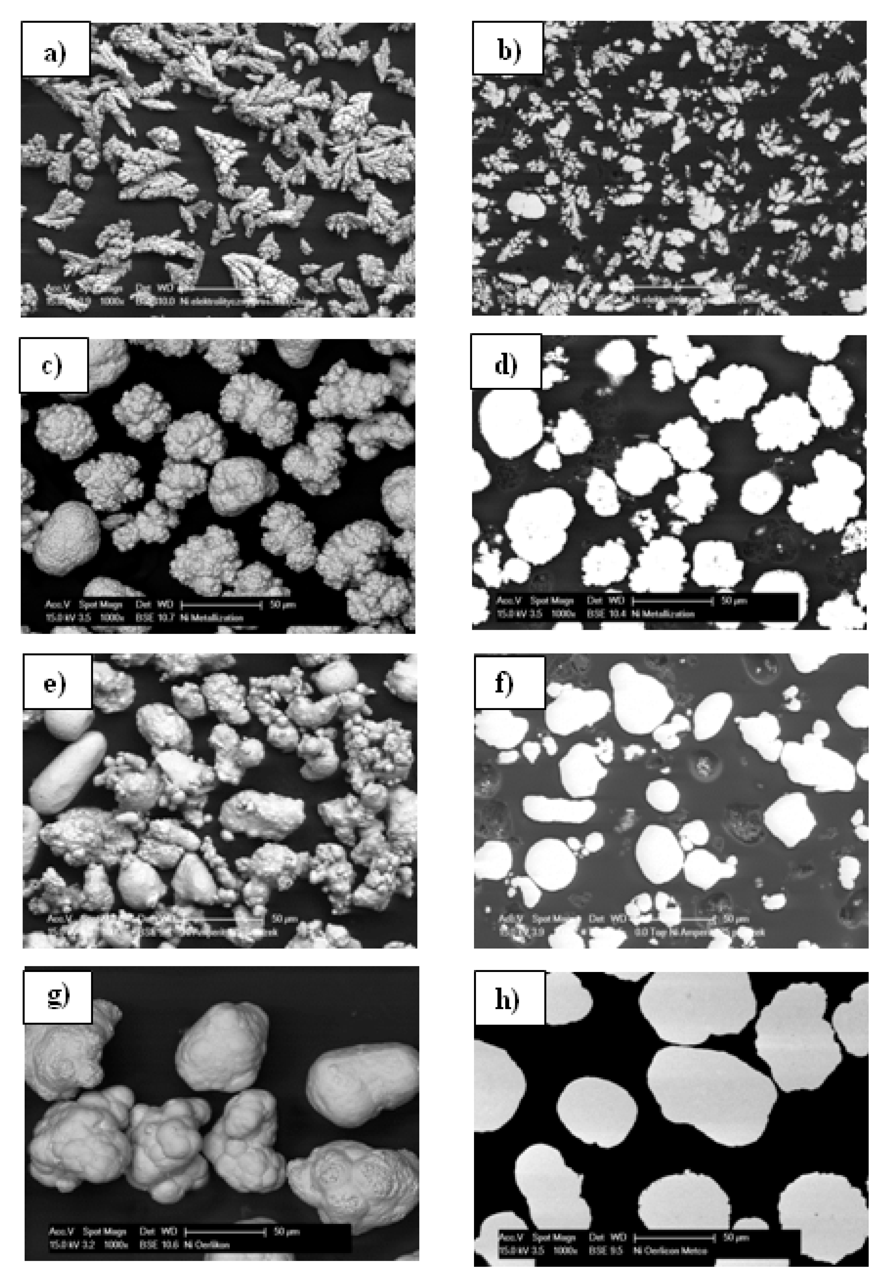
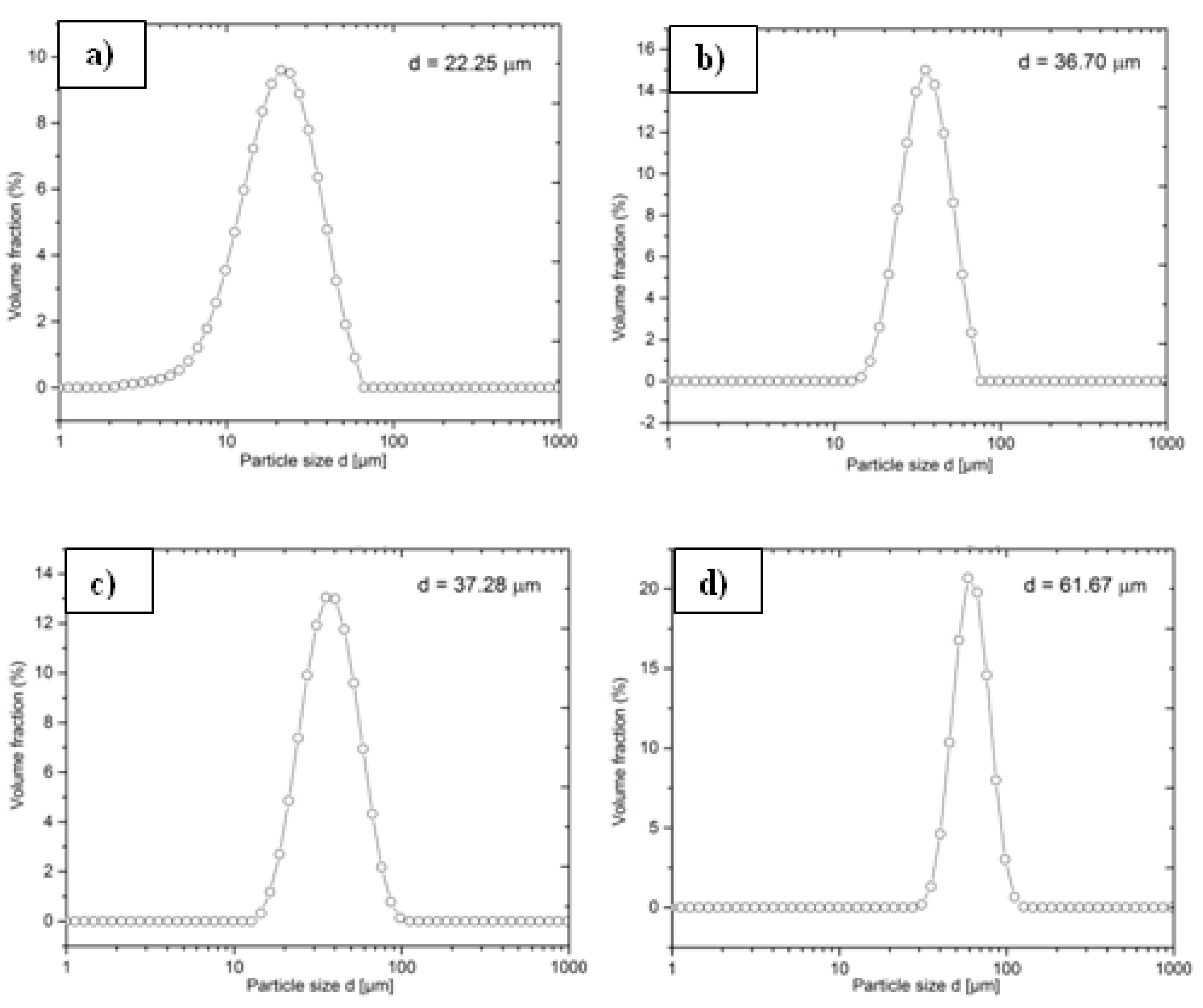
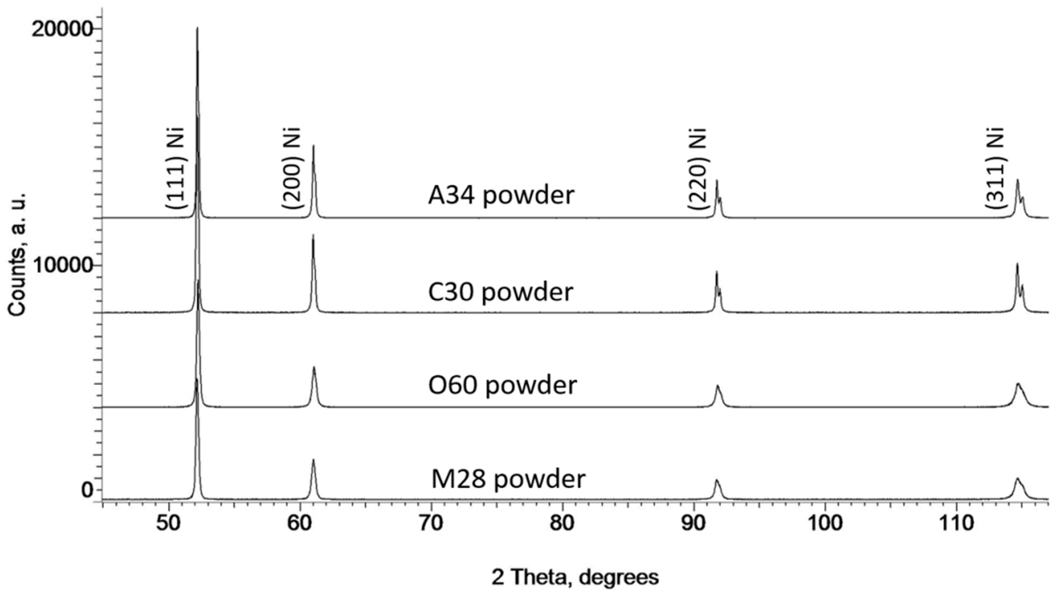
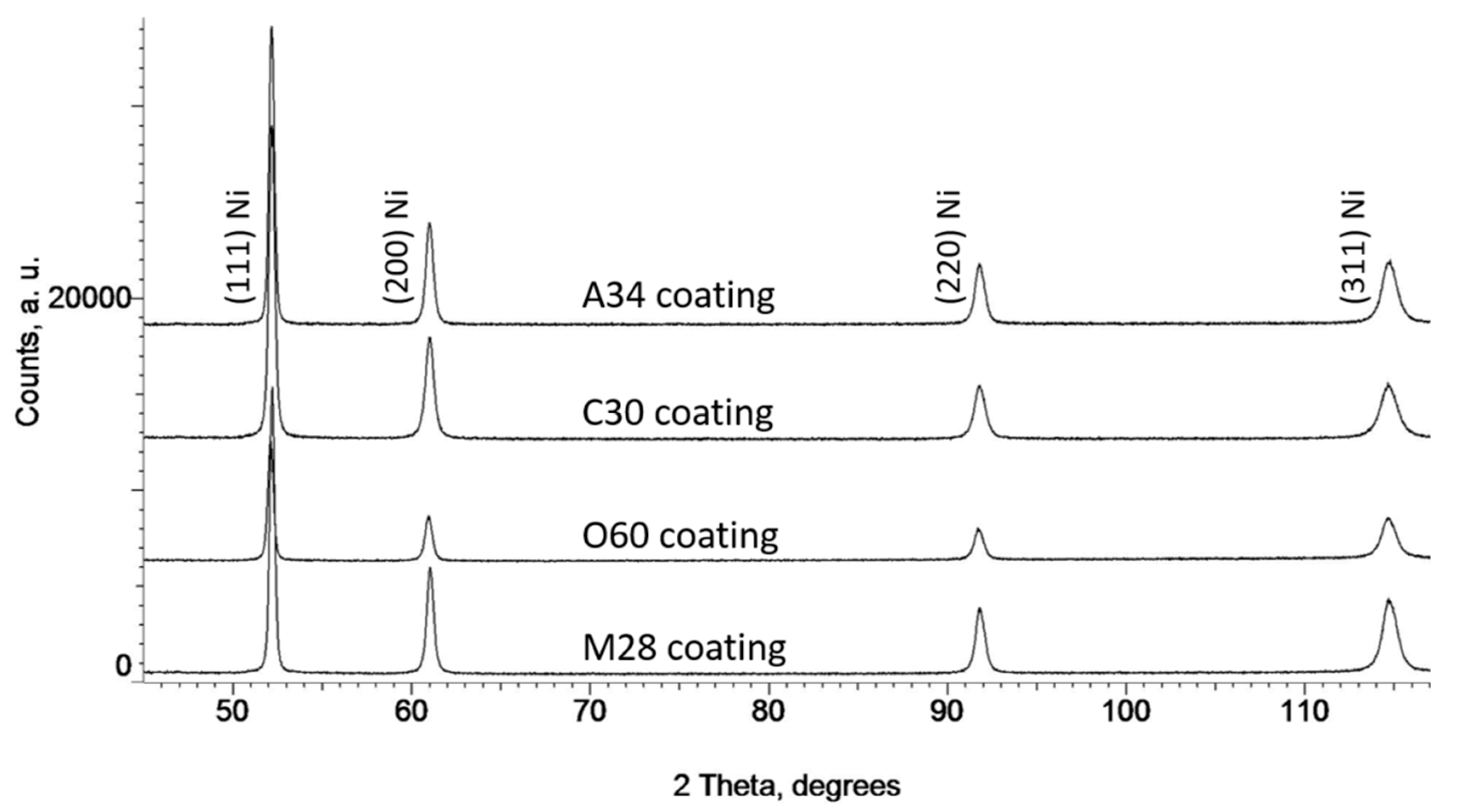
3.1. Microstructural Characteristics of Ni Powders

Figure 2 shows the morphology and cross-section of the nickel powders used. All powders differ significantly in grain morphology. Grains of C30 electrolytic powders present typical dendritic morphology. Particles have a diversified structure, some consist of one branch, but most have a strongly branched shape of different sizes (Figure 2a). The inter-granular interspace is clear between the branches of the dendrites on the cross-section of the powder, which means that its porosity is considerable (Figure 2b). Grains of the M28 powder are of irregular spherical shape. Slight inequalities are seen on the surface of some grains but most of them are very rough. These grains consist of fine particles of the size of 20–40 μm (Figure 2c) as a result of precipitation and aggregation during the hydrogen-reduction method. The cross-section of powder grains showed their dense microstructure without any inclusions. However, some grains revealed small pores inside (Figure 2d). A34 and O60 powders were manufactured using the hydrogen-reduction method, just as in the case of the M28 powder. The morphology of the A34 grains is very similar to that of the M28 powder, but the shape of their grains considerably varies. There are more elongated particles of both smooth and rough surfaces (Figure 2e). Moreover, this powder showed dense microstructure, and no pores were observed inside the grains on the cross-sectional micrographs of some particles (Figure 2f). The fourth powder, O60, consists of significantly bigger grains of irregular shape which are close to spherical. Some of the particles have smooth surfaces, and others are shapeless (Figure 2g). The cross-section of the powder particles revealed their dense microstructure without any pores (Figure 2h).
The grain size distributions of nickel powders are shown in Figure 3. The graph for the electrolytes of the C30 powder presents a less steep course of the curve owing to a larger grain size differentiation. This powder has the smallest mean diameter of particles 22.25 μm (Figure 3a). Moreover, graphs of density distribution for the M28, A34, and O60 powders showed curves with a steep incline and a narrow cut typical for trade materials.
The mean diameter of M28 and A34 powders are nearly the same 36.70 μm and 37.28 μm, respectively, (Figure 3b,c respectively), despite differences in their morphology. However, powder O60 consists of almost twice larger grains of mean diameter 61.67 μm (Figure 3d), which is visible in the picture of their morphology (Figure 2g). The cross-section and surface morphology of all cold-sprayed nickel coatings are shown in Figure 4. In all cases, the grains of the nickel powder that hit the substrate have deformed and exactly filled its roughness caused by the grit-blasting. It is clearly visible that regardless of morphology and grain size, the coatings formed adhere very well to the substrate. There are no voids, pores, and inclusions at the interface for all the coatings, which may indicate their very good adhesion (Figure 4a,c,e,g). Microstructures of C30 and A34 coatings are completely homogenous with negligible porosity, despite significant differences in the morphology and grain size deposition of sprayed nickel powders (Figure 4b), and Figure 4h). In the case of the C30 coating, the morphology of the C30 powder plays an essential role. Dendritic particles can achieve higher flying velocities due to their expanded irregular shape. Such a form of powder grains leads to higher drag force in the gas stream [33]. Consequently, the time spent in the divergent part of the nozzle is shorter, which limits the particle cooling as a result of decreasing the temperature of the expanding gas. The higher temperature of particles is associated with their greater plasticity and favors particle deposition at a lower critical velocity [34]. As a result of the higher impact velocity and higher temperature, a coating with negligible porosity is created despite its relatively small particle size (Figure 4b). A similar microstructure, characterized by trace porosity, was obtained as a result of the spraying powder A34 (Figure 4h). In addition, the shape of the powder grains is another important parameter influencing the coating deposition. Thus, powders of more irregular shape (C30 and A34, create more dense coatings than powders of nearly spherical shape (M28 and O60). This corresponds with results presented in the literature [26]. Significantly larger grains (dC30 = 22.25 μm vs. dA34 = 37.28 μm) formed a coating with high cohesion. No boundaries between deformed grains were visible. On the other hand, the microstructure of the M28 coating presented in Figure 4e showed severely deformed Ni grains with visible borders between them. In addition, there are also small pores between the deformed powder grains. Traces of such borders and small pores can also be observed in the microstructure of the O60 coating formed from the largest nickel grains (Figure 4k). The bonding between the deformed particles is a result of adiabatic shear instability and mechanical interlocking [35,36]. Adiabatic shear instability takes place when the critical velocity of particles is exceeded, which causes the occurrence of shearing at high pressure, followed by an increase in temperature at the high strain rate of the deformation. The heat generation and high deformation of the powder were mainly localized near the interface region causing the generation of shear bands by adiabatic shear localization [27]. An adiabatic softening of particles favors the good connection of their surfaces by plastic deformation. These particles of nearly spherical shape experienced smaller plastic deformation during the impact than those possessing rougher surfaces and of more irregular shape. As a result, the traces of particle borders were observed. Borders visible between deformed particles in the cross-section of coatings M28 and O60 testify the occurrence of the phenomenon of mechanical interlocking. This seems obvious for the powder O60 whose grains are large (dO60 = 61.67 μm) and their significant part may not exceed the critical velocity necessary for the adiabatic shear instability process to occur. However, in the case of the M28 coating sprayed with powder of the grain size comparable to that of the powder A34 (dA34 = 37.28 μm vs. dM28 = 36.70 μm), the occurrence of borders visible between the deformed particles indicates the lower plasticity of this powder. Figure 4c,f,i,l present the morphology of the surface of sprayed coatings obtained from all four nickel powders. The differences visible on the surface of the coatings are a reflection of the morphology of the sprayed grains. The surface of the C30 coating consists of small significant deformed particles (Figure 4c). This is the result of the deformation of the fine dendrites which create a relatively smooth surface.
Very small residual porosity was found between the particles forming the surface. The M28 coating surface comprises significantly bigger grains, most of which are plastically deformed with different degrees of flattening (Figure 4f). In addition, slightly deformed grains that have retained their initial morphology are visible. Some pores could be found between some of the particles resulting from the poor combination of powder grains. Very well-deformed powder grains are very well visible on the surface of coating A34 (Figure 4i). These particles tightly adhere to each other creating a coherent surface. Even small pores on the surface of this coating are not visible. Significantly bigger nickel particles with slight deformation could be found on the surface of the O60 coating because they have been deposited from the powder of the largest diameter of grains (Figure 4l). Porosity between deformed particles is clearly seen in the case of the O60 coatings because of the largest particles which are slightly deformed and do not form a cohesive surface.
Figure 5 and Figure 6 show the X-ray diffraction patterns obtained for both the Ni powder feedstock and the cold-sprayed coatings, respectively.
All diffraction peaks indicate that all nickel powders and cold-sprayed coatings consist of Ni atoms exclusively. No traces of oxide peaks were detected in any of the materials tested. As can be seen from Figure 5 and Figure 6 the peaks referring to the powders were much sharper compared to those coming from the corresponding coatings. The crystallite size of A34, C30, O60, and M28 powders used were 132, 110, 81, and 89 nm, respectively. The X-ray diffraction peaks of cold-sprayed coatings were significantly wider (Figure 6). According to the XRD reflection line broadening, the Ni crystallite sizes were evaluated to be 50, 42, 45, and 53 nm in the metallic coatings A34, C30, O60, and M28, respectively. The cold spraying caused a significant decrease in the feedstock crystallite size. Its highest reduction was revealed in the coatings formed from the A34 and C30 powders.

3.2. Chronopotentiometric Measurements

Open circuit potential (EOCP) measurements are one of the electrochemical methods used to evaluate and estimate the corrosion performance of coating layers [37]. Figure 7 shows the evolution of EOCP for the Al7075 substrate, and nickel coatings (Table 1).
For the Al7075 alloy during 20 h, the EOCP varies from a lower value (of about −780 mV) to a relatively stable higher value (of about −700 mV). This stage may correspond to the process of solution filling or penetrating into the pores and crackers in the substrate surface (Figure 7, curve (a)). Then, with an increase in exposure time; the EOCP values do not change. It is likely that the surface of the Al7075 substrate has been covered with a protective layer that protects the substrate from dissolving in an aggressive chloride environment.
However, as far as all nickel coatings on the Al7075 alloy are concerned, when the samples are exposed to a chloride environment for about 30 h, the change in EOCP values towards negative values was observed. Therefore, the surface state changed by the severe pitting attack should be responsible for the degradation of the EOCP (Figure 7, curves (b–e)). It could also be seen that the EOCP of the nickel coating does not further shift negatively at a longer immersion time, which suggests that Ni coatings can isolate the Al7075 substrate against the corrosive effect of chlorides, which further supports the postulation that micro-pores and micro-crackers in nickel coatings do not act as shortcut tunnels for the solution to reach the substrate. This could be attributed to the dense structure of the cold-sprayed Ni coating (Figure 4a,b) for the C30 powder. In addition, the fine-grain structure (Figure 2a,b) could also contribute to the higher EOCP (Figure 7, curve (e)) of the cold-sprayed nickel coating.

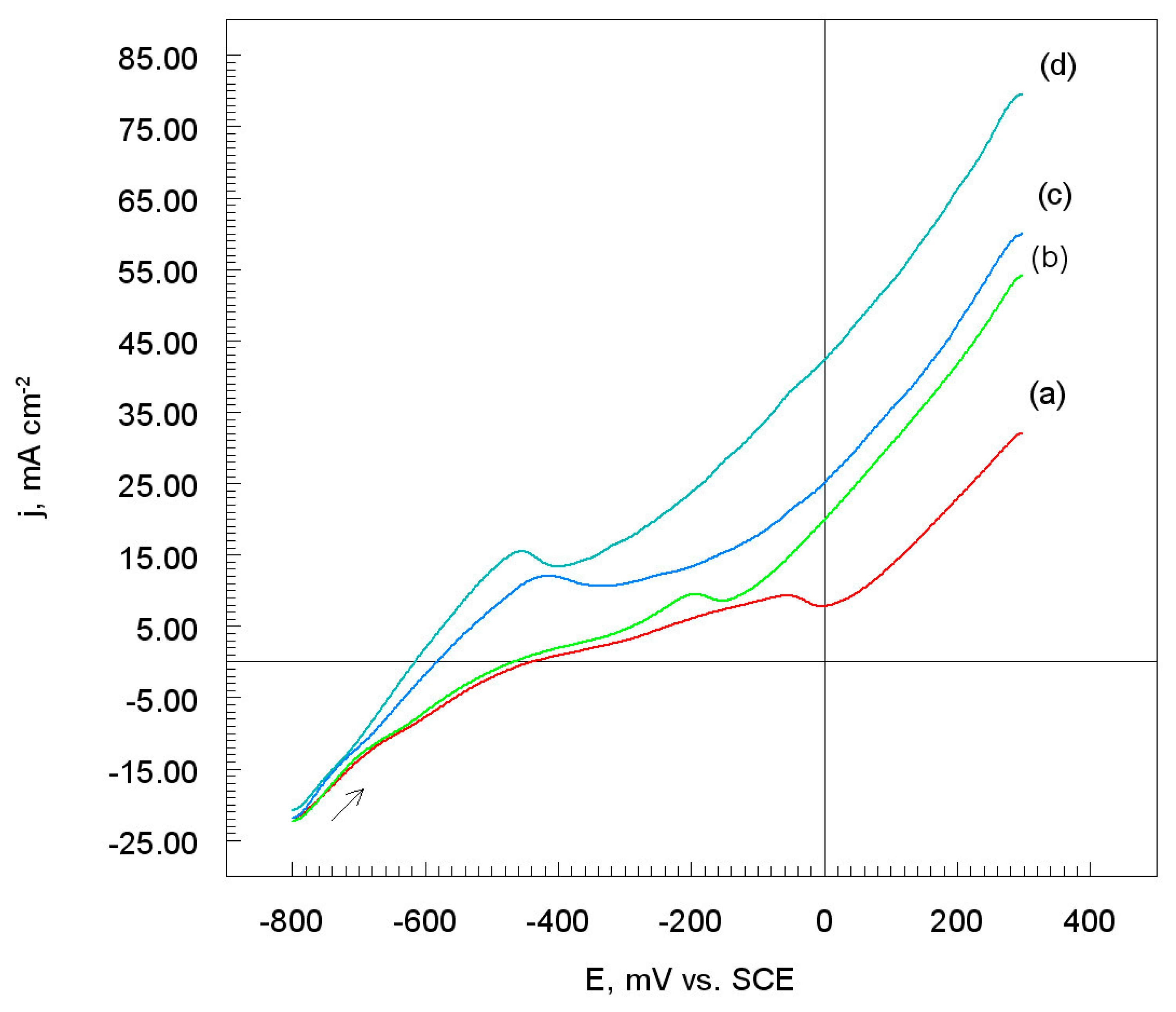
3.3. Potentiodynamic Polarization Measurements

Potentiodynamic polarization (LSV) measurements were carried out in order to gain knowledge concerning the kinetics of the cathodic and anodic reactions. The potentiodynamic polarization curves for the materials tested are shown in Figure 8.
It could be assumed that the M28 coating (20–40 μm) is the most resistant to electrochemical corrosion whereas the O60 coating (50–75 μm) is the most susceptible.
The cathode branches (Figure 8) correspond to the simplified reduction of a hydrogen ion [30,31]:
Ni + 2 H+ → Ni + H2 − 2 e.
When the potential of the electrode was changed in the anodic direction, the adsorption layer with the participation of chloride ions [33] was created on the electrode surface:
Ni + Cl + H2O → (NiClOH)ads + H+ + e
(NiClOH)ads → (NiClOH)ads + e
The adsorption layer of (NiClOH)ads on the nickel surface corresponds to the peaks on the potentiodynamic polarization curves which appear in the range of potentials from −60 mV to −470 mV vs. SCE (Figure 8). However, moving the peaks potential to more negative values indicates that the structure and properties of the (NiClOH)ads layer depend on the size of the nickel powders (Table 1).
The (NiClOH)ads layers partially prevent the electrode surface from further oxidation in the chloride environment. Unfortunately, the adsorption layer (reaction (4)) in the acidic solution was dissolved in accordance with a simple chemical reaction:
(NiClOH)ads + H+ → Ni2+ + Cl + H2O.
The acidic chloride electrolyte was not deoxidized, and the next anodic reaction of nickel was as follows:
Ni2+ + 2 H+ + O2 → Ni(OH)2 + 4e.
The electrode surface was probably coated with a porous nickel oxide layer according to the reaction:
Ni(OH)2 → NiOads + H2O.
However, a similar reaction mechanism for iron in the acidic chloride solution was proposed by Chin and Nobe [38].

3.3.1. Corrosion Electrochemical Parameters

The corrosion electrochemical parameters of nickel coatings in an aggressive chloride solution were listed in Table 2.
In the case of nickel coatings, a shift in the corrosion potential (Ecorr) towards negative values was observed. The jcorr is the largest for the nickel powder of size 50–75 μm (Table 2). Therefore, an increase in the porosity of nickel coatings is accompanied by an increase in the size of nickel powders. On the other hand, the cathodic (βc) and anodic (βa) Tafel slope was changed in the direction of decreasing values. This means that the mechanism of cathodic (2), and anodic (3)–(7) reactions depends on the size of the nickel grains which were used for the production of Ni coatings.

3.3.2. Polarization Resistance and Corrosion Rate

The polarization resistance (Rp) of nickel coatings were determined on the basis of the slope of potentiodynamic polarization curves (Figure 8) [31,32]. Moreover, the corrosion rate (vcorr) was calculated on the basis of Equation (1). The Rp and vcorr values for all the nickel coatings cold-sprayed on the Al7075 alloy were given in Table 3. It was found that the polarization resistance of Ni coatings decreases with an increase in the diameter of nickel powders (Table 1).
Therefore, in the case of the O60 coating, the exchange of electrical charge and mass between the electrode and the electrolyte solution was facilitated. On the other hand, the corrosion rate of M28 coating was more than twice as great as the corrosion rate of nickel coating denoted as O60 (Table 3). It seems obvious that the metallographic structures of M28 and O60 nickel coatings are completely different. The structure of the O60 nickel coating is probably less compact than the structure of the M28 nickel coating. Therefore, chloride ions readily penetrate into the structure of the Ni coatings. Thus, the porosity of the nickel coating causes high corrosion rates of materials.

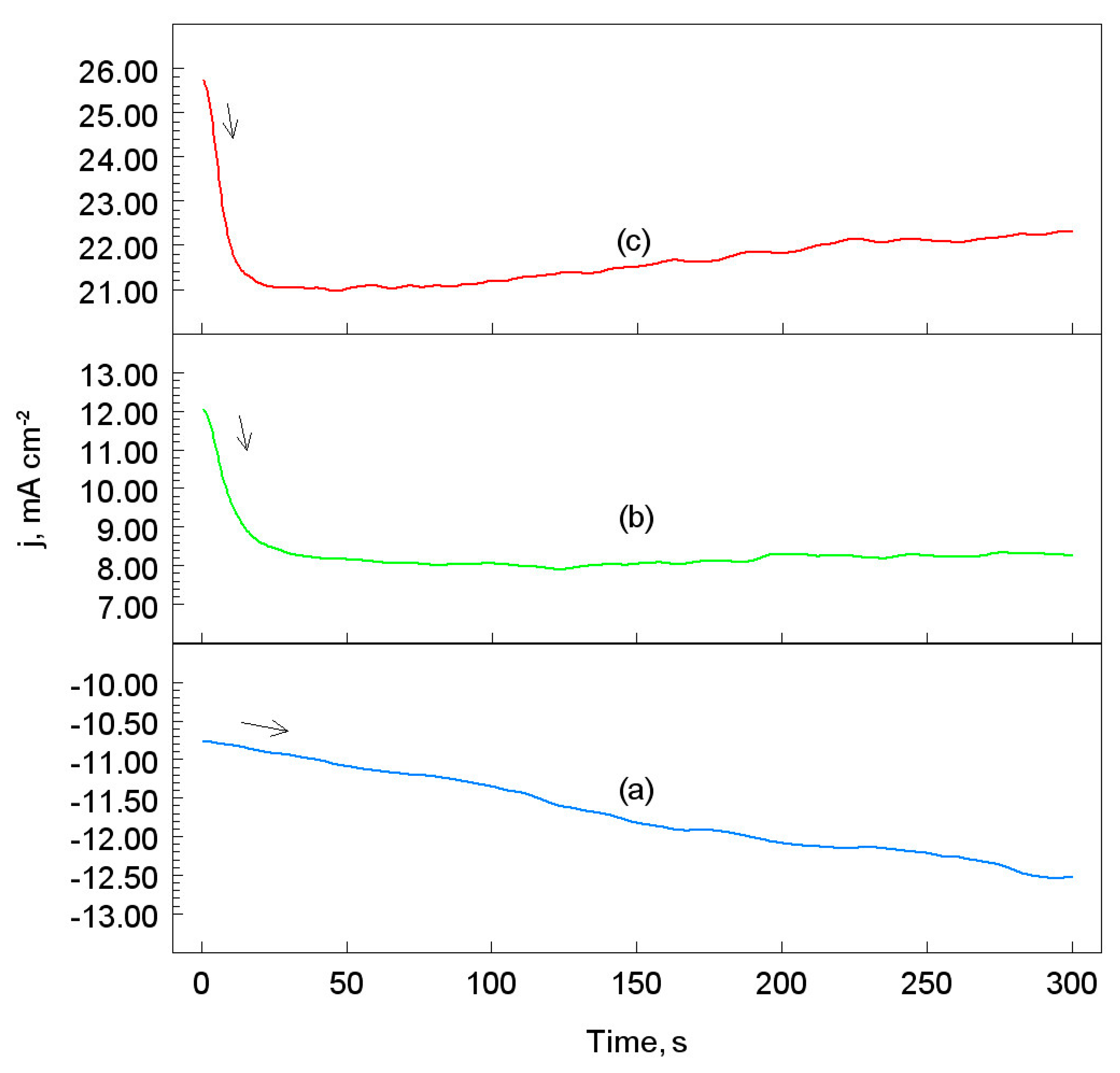
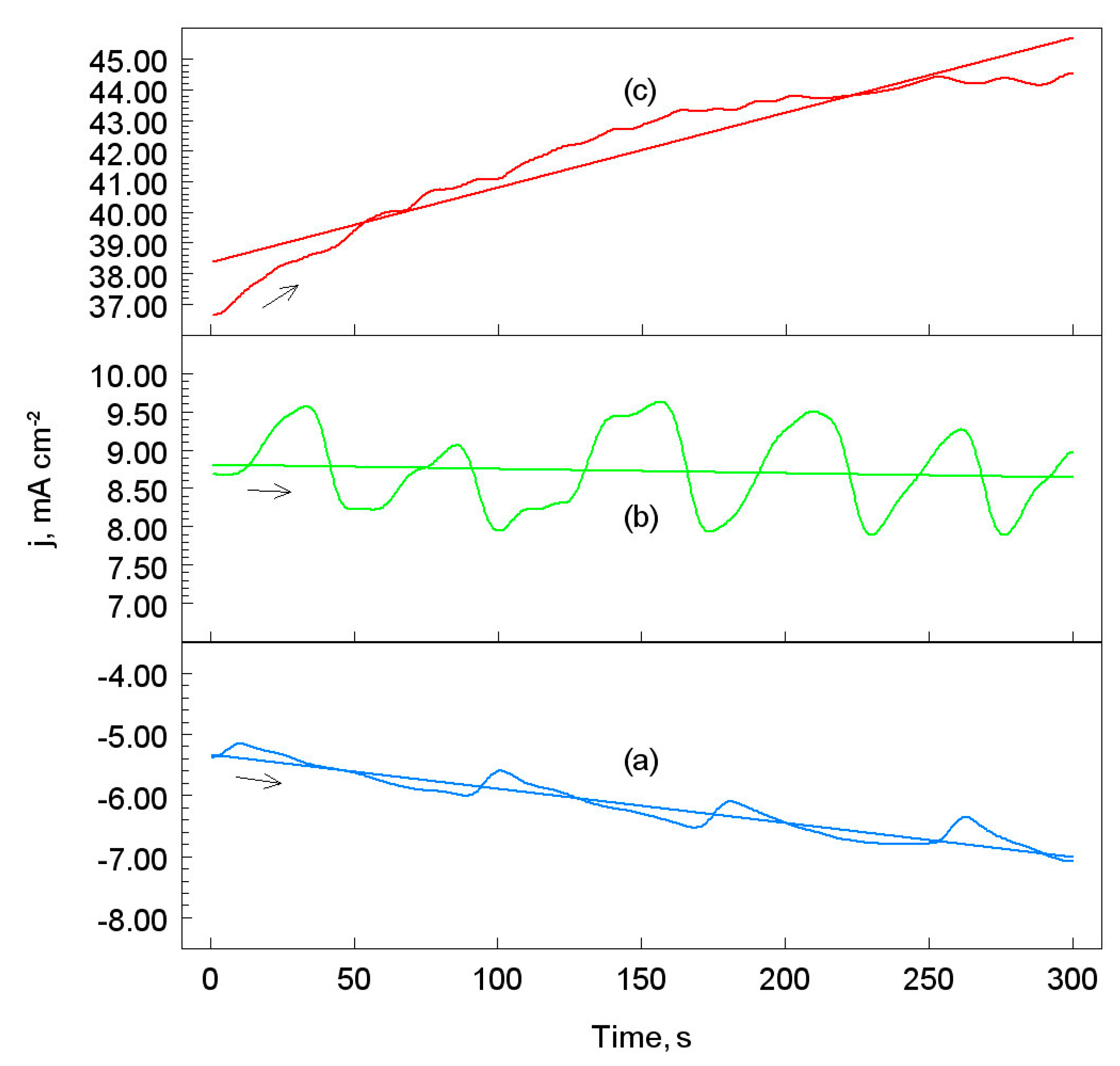
3.4. Chronoamperometric Measurements

The study of the current response as a function of time at a suitably selected potential is called chronoamperometry (ChA). Figure 9 and Figure 10 show chronoamperometric curves for the M28 and O60 nickel coatings on the Al7075 substrate. However, similar chronoamperometric curves were obtained for other Ni coatings. The potentials of the working electrode were selected according to the polarization curves (Figure 8, curves (a), and (d)).
The increase in the cathodic current density versus the time of electrolysis, curve (a) (Figure 9 and Figure 10), was caused by the reduction of the hydrogen ion (reaction (2)). This means that the process of producing hydrogen gas on the M28 and O60 coatings is not inhibited. The curve (b) (Figure 9 and Figure 10) should be attributed to the formation of the adsorption of the (NiClOH)ads layer on the nickel coatings (reactions (3) and (4)). Therefore, no significant changes in the anode current density means that the (NiClOH)ads layer is tight and the electrolyte does not reach the electrode directly, and, consequently, no oxidation of nickel coatings was observed. On the other hand, the clearly wavy curve (Figure 10, curve (b)) indicates that the (NiClOH)ads layer is not evenly distributed on the surface of the nickel electrode which was made of large nickel grains, i.e., 50–75 μm (Table 1). Moreover, an increase in the potential in the more positive direction (i.e., 150 mV vs. SCE) results in increasing the anodic current density (Figure 9 and Figure 10, curve (c)) because the (NiClOH)ads layer dissolves according to the reaction (5).
As a consequence, the surface of the nickel coatings was covered with black porous nickel(II) oxide according to reactions (6) and (7). Therefore, the NiOads was not an effective barrier to protect the Ni coating from oxidation in the aggressive chlorine environment.

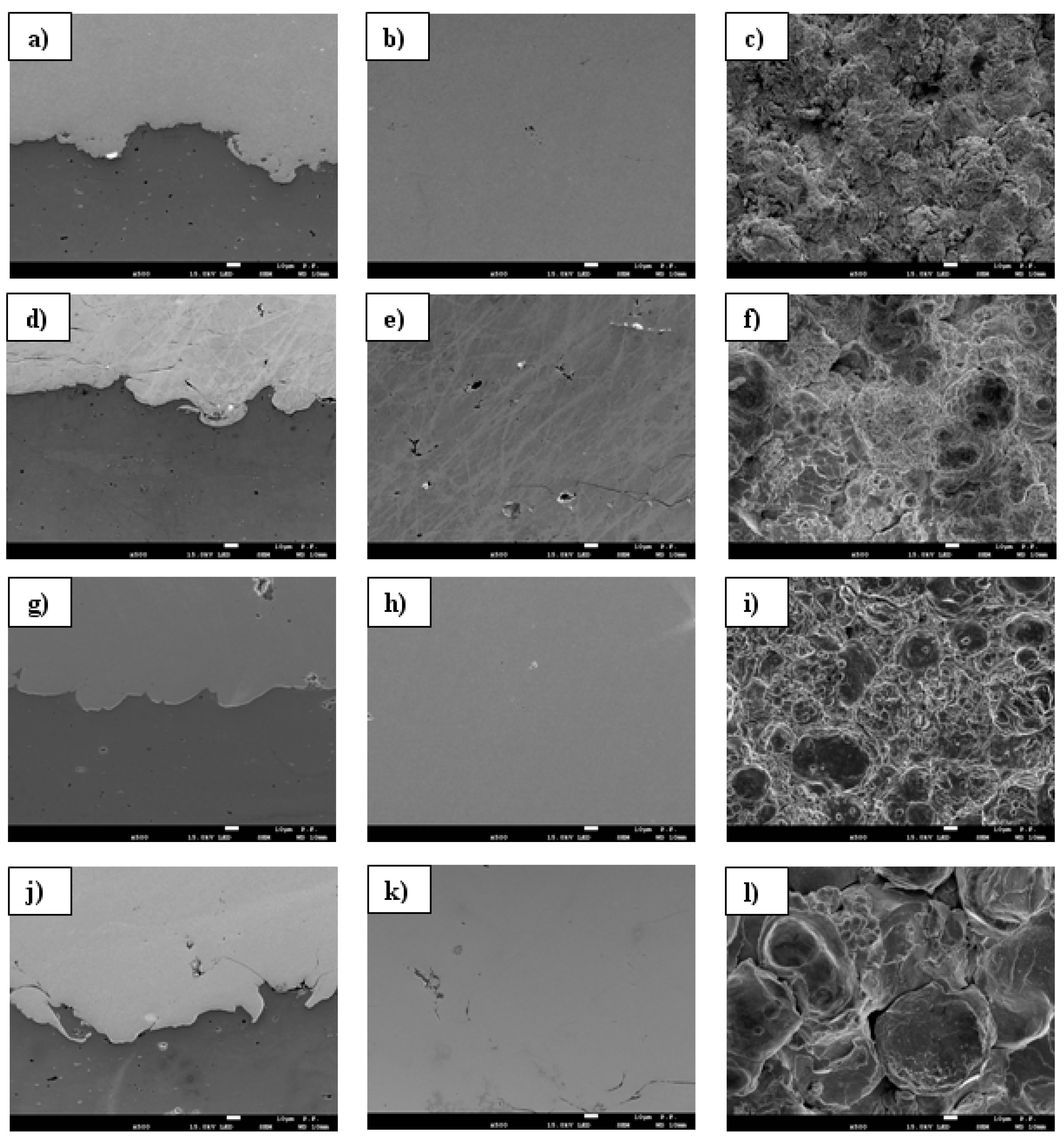
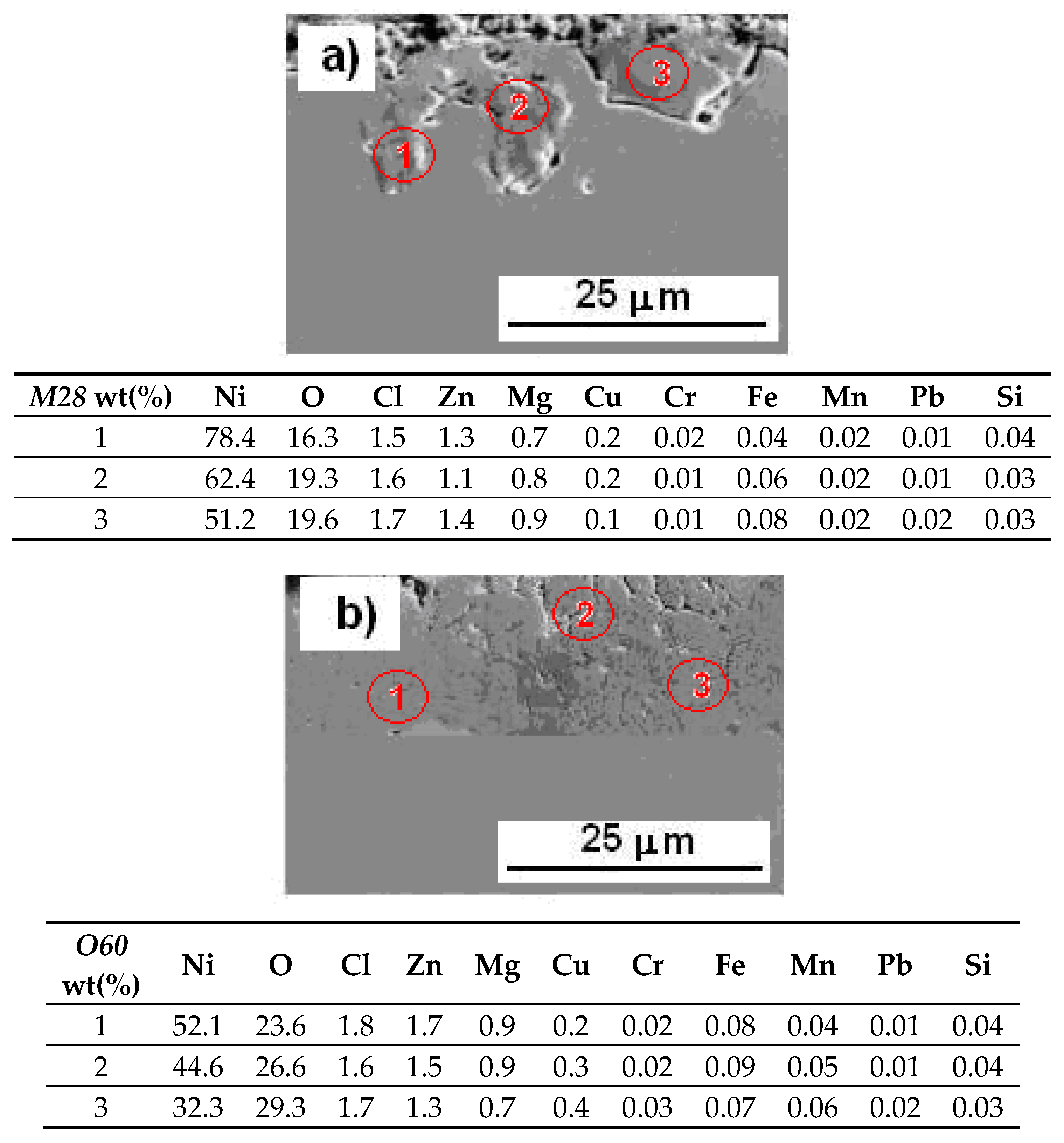
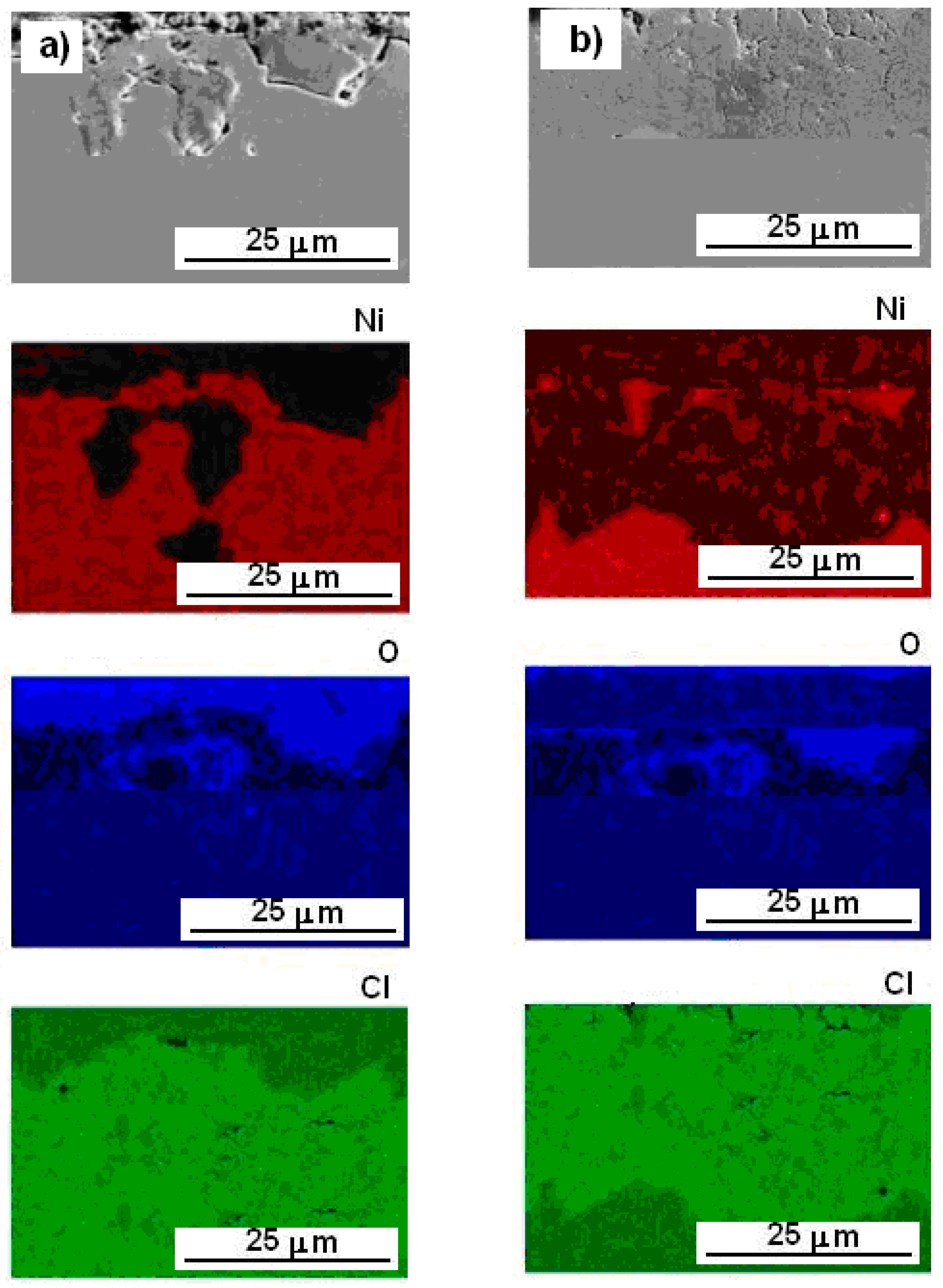
3.5. SEM/EDS Elemental Mapping

In order to characterize the composition of nickel coatings after corrosion damage, SEM observations with EDS analysis was made. However, nickel coatings were tested after corrosion tests in an acid chloride environment. Figure 11 shows the SEM/EDS results for the M28 and O60 nickel coatings.
The SEM/EDS elemental mapping obtained for the M28 and O60 nickel coatings confirms the extensive corrosion of both samples in an aggressive chloride environment (reactions (3)–(5)). The most severe corrosion damage caused by the penetration of chloride ions was observed for the O60 nickel coating (Figure 11b). Moreover, on the surface of both samples there is oxygen (reactions (6) and (7)) and a small amount of chlorine. The SEM/EDS analyses of the surface corrosion products on the nickel coatings after the corrosion test are reported in Figure 12. The corresponding composition of the surface layers were listed in the tables below the analyzed sample areas.
It turned out that the content (wt%) of nickel on the sample surface is on average 64% and 43%, and oxygen 18% and 26% for the M28 and O60 coatings, respectively. However, the surface concentration of other elements is small and it has no significant effect on the anti-corrosion properties of nickel coatings. The formation of the NiOads layer involves the adsorption of dissolved oxygen in an aggressive corrosive environment (reaction (7)).

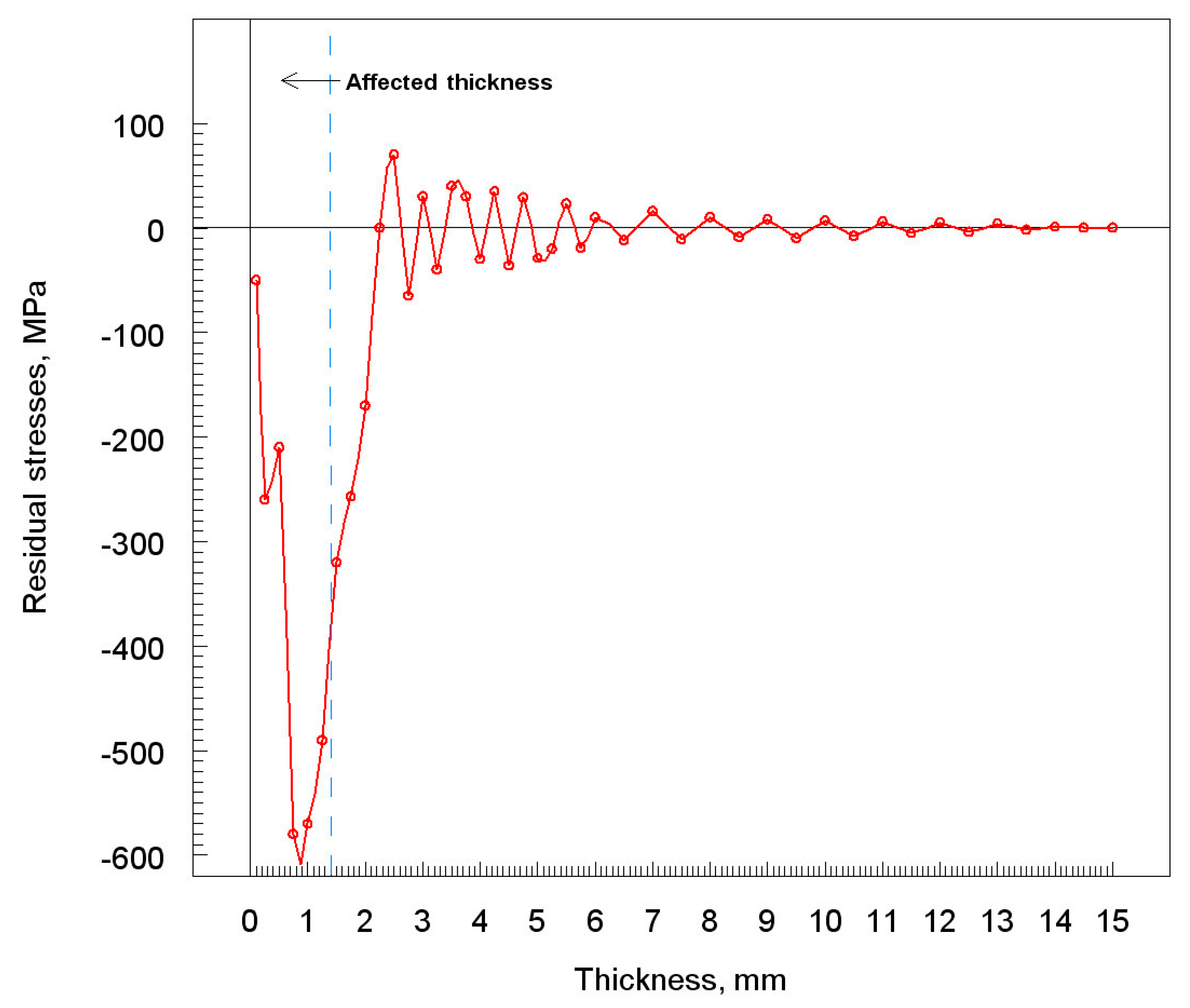
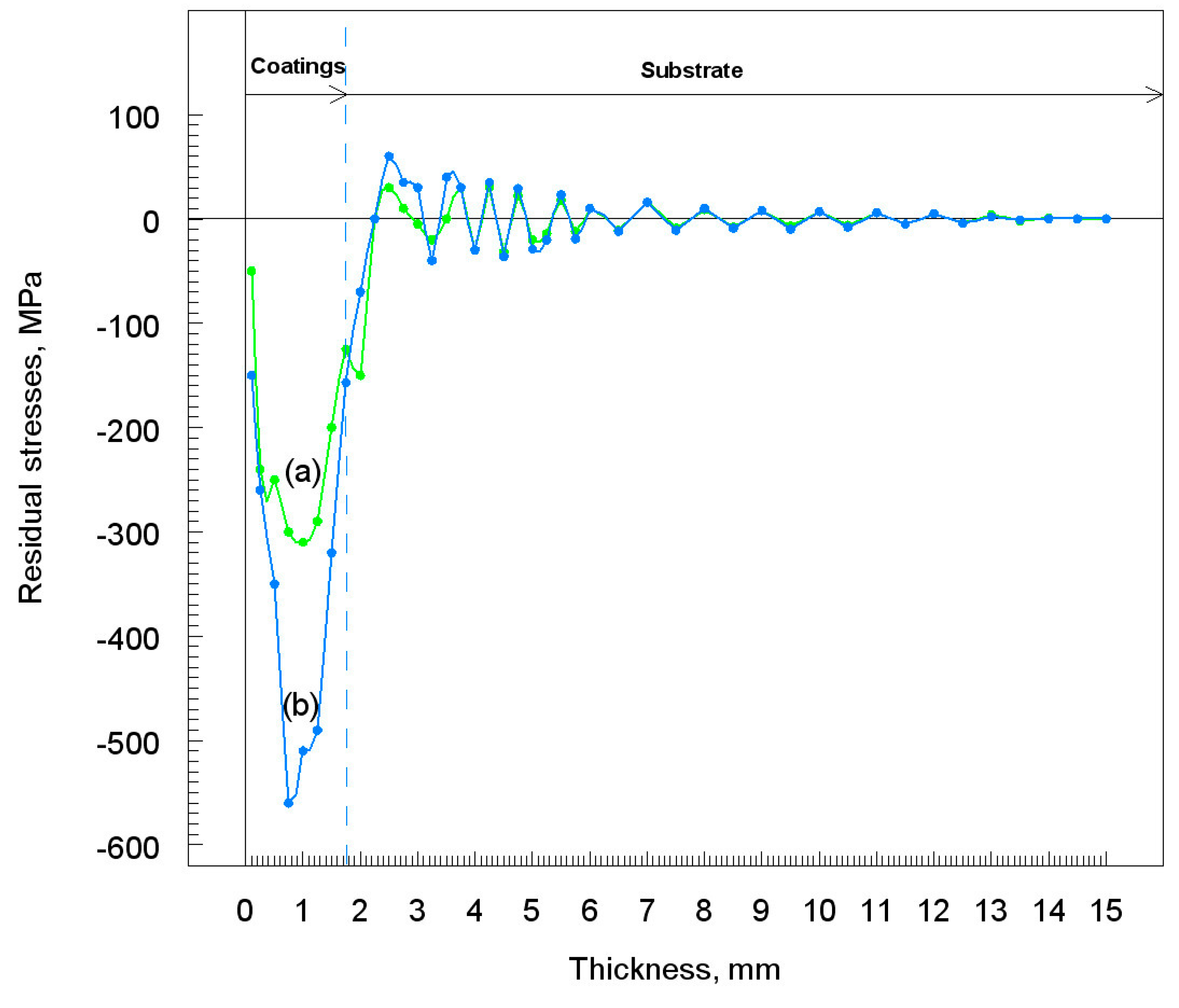
3.6. Residual Stress

The determination of the residual stress for the different specimens was based on the measurement of deformations during the electrochemical controlled thinning of the deposits [39]. The deposits were removed by electrochemical polishing across the specimen surface. Figure 13 shows the residual stress profile after the grit blasted of Al7075 alloy.
It was found that residual stress has an average value of about −250 MPa with a peak of more than −600 MPa at a depth of about 0.9 mm. Without any doubt, the high value of the stress is mainly due to the severe surface roughness generated by the grit-blasting of the Al7075 alloy. Figure 14 shows the residual stress profile of M28 and O60 nickel coatings on the Al7075 substrate. On the other hand, similar values of residual stress profiles were obtained for other coatings (i.e., C30 and A34).
It turned out that the generated residual stress for the M28 and O60 nickel coatings has an average value of about −260 MPa and −510 MPa, respectively. It is understandable that the high values of residual stress are mainly due to the cold spraying procedure. A constant bombardment of particles on the substrate and coating area is known as a major feature that results in increasing the residual stresses. Thus, large particles of the nickel powder (50–75 μm) cause a high value of residual stress, compared to small grains (in this case 20–40 μm) (Figure 14, curves (a), and (b) in the depth of nickel coating produced by cold spraying method). Although, the processing gas temperature was less than the melting point of the materials involved, it was postulated that compressive residual stress was induced by the previous grit-blasting of the Al7075 substrate, and the strong interaction of nickel particles with the substrate material. In this way, the coatings deposited with Ni powders of smaller grain size (M28) were more resistant to electrochemical corrosion in chloride solution than the deposits obtained with a bigger size of grains (O60). The Ni coating deposited from the powder (O60) of the bigger size showed the worst electrochemical corrosion resistance. This may be due to fact that O60 Ni particles on the surface of the substrate were slightly deformed and bounded together. Therefore, a porous nickel layer was obtained during the CS process. On the other hand, a high corrosion rate of material was observed in the aggressive chloride environment.

4. Conclusions

  • Nickel coatings adhere well on the Al7075 alloy, and the most smooth surface structure was obtained for Ni powders of irregular spherical and dendritic morphology.
  • The mechanism of electrochemical corrosion of nickel coatings in acidic chloride solutions is a multi-stage process, and the main product of corrosion is NiOads. The oxide layer is porous and does not protect the Al7075 substrate from the penetration of an aggressive chloride solution.
  • The polarization resistance of Ni coatings decreases with an increase in the size of nickel powders, which means that it is easy to replace the electrical charge and mass between the electrode and the electrolyte solution.
  • The corrosion rate of nickel coatings in the chloride solution increases with an increase in the grain size of nickel powders. Moreover, the lowest corrosion rate of the tested coatings was observed for Ni grains of irregular spherical or dendritic morphology.
  • The constant bombardment of particles on the substrate causes the emergence of residual stress. The highest residual stress value was observed for large grains of nickel powder.

Author Contributions

Conceptualization, M.S. and W.Z.; formal analysis, M.S. and A.G.; investigation, M.S. and A.G.; methodology, M.S. and W.Z.; writing-original draft, M.S. and A.G.; writing-review and editing, M.S.

Funding

These studies were not financed from outside.

Acknowledgments

The authors thank Katarzyna Staszewska-Samson for cooperation and participation in experiments.

Conflicts of Interest

The authors declare no conflict of interest.

References

  1. Karthikeyan, J. Cold Spray Technology. Adv. Mater. Process. 2005, 163, 33–35. [Google Scholar]
  2. King, P.C.; Bae, G.; Zahiri, S.H.; Jahedi, M.; Lee, C. An experimental and finite element study of cold spray copper impact onto two aluminum substrates. J. Thermal. Spray Technol. 2010, 19, 620–634. [Google Scholar] [CrossRef]
  3. Lee, M.S.; Choi, H.J.; Choi, J.W.; Kim, H.J. Application of Cold Spray Coating Technique to an Underground Disposal Copper Canister and its Corrosion Properties. Nucl. Eng. Technol. 2011, 43, 557–566. [Google Scholar] [CrossRef]
  4. Wang, Q.; Birbilis, N.; Zahang, X. On the Formation of a diffusion bond from cold-spray coatings. Metall. Mater. Trans. A: Phys. Metall. Mater. Sci. 2012, 43, 1395–1399. [Google Scholar] [CrossRef]
  5. Marrocco, T.; McCartney, D.G.; Shipway, P.H.; Sturgcon, A.J. Production of titanium deposits by cold-gas dynamic spray: Numerical modeling and experimental characterization. J. Thermal. Spray Technol. 2006, 15, 263–272. [Google Scholar] [CrossRef]
  6. Price, T.S.; Shipway, P.H.; McCartney, G.D. Effect of Cold Spray Deposition of a Titanium Coating on Fatigue Behavior of a Titanium Alloy. J. Thermal. Spray Technol. 2006, 15, 507–512. [Google Scholar] [CrossRef]
  7. Wong, W.; Rezaein, A.; Irissou, E.; Legoux, J.G.; Yue, S. Cold spray characteristics of commercially pure Ti and Ti-Al4V. Adv. Mater. Res. 2010, 89-91, 639–644. [Google Scholar] [CrossRef]
  8. Koivuluoto, H.; Nakki, J.; Vuoristo, P. Corrosion properties of could-sprayed tantalum coatings. J. Thermal. Spray Technol. 2008, 18, 75–82. [Google Scholar] [CrossRef]
  9. Koivuluoto, H.; Bolelli, G.; Lusvarghi, L.; Casadei, F.; Vuoristo, P. Corrosion resistance of cold-sprayed Ta coatings in very aggressive conditions. Surf. Coat. Technol. 2010, 205, 1103–1107. [Google Scholar] [CrossRef]
  10. Bolelli, G.; Bonferroni, B.; Koivuluoto, H.; Lusvarghi, L.; Vuoristo, P. Depth-sensing indentation for assessing the mechanical properties of cold-sprayed Ta. Surf. Coat. Technol. 2010, 205, 2209–2217. [Google Scholar] [CrossRef]
  11. Xiong, Y.; Bae, G.; Xiong, X.; Lee, C. The effects of successive impacts and cold welds on the deposition onset of cold spray coatings. J. Thermal. Spray Technol. 2010, 19, 575–585. [Google Scholar] [CrossRef]
  12. Wong, W.; Irissou, V.P.; Sone, M.; Bernier, F.; Legoux, G.; Fukanuma, H.; Yue, S. Cold spray forming of Inconel 718. J. Thermal. Spray Technol. 2012, 21, 1–9. [Google Scholar] [CrossRef]
  13. Luo, X.T.; Li, Y.J.; Li, C.X.; Yang, G.J.; Li, C.J. Effect of spray conditions on deposition behavior and microstructure of cold sprayed Ni coatings sprayed with a porous electrolytic Ni powder. Surf. Coat. Technol. 2016, 289, 85–93. [Google Scholar] [CrossRef]
  14. Koivuluoto, H.; Milanti, A.; Bolelli, G.; Lusvarghi, L.; Vuoristo, P. High-pressure cold-sprayed Ni and Ni-Cu coatings: Improved structures and corrosion properties. J. Thermal. Spray Technol. 2014, 23, 98–103. [Google Scholar] [CrossRef]
  15. Gouda, V.; Selim, I.; Khedr, A.; Fathi, A. Pitting corrosion of Monel-400 alloy in chloride solutions. J. Mater. Sci. Technol. 1999, 15, 208–212. [Google Scholar]
  16. Sherif, E.; Almajid, A.; Bairamov, A.; Al-Zahrani, E. Corrosion of Monel-400 in aerated stagnant arabian gulf seawater after different exposure intervals. Int. J. Electrochem. Sci. 2011, 6, 5430–5444. [Google Scholar]
  17. Al-Abdallah, M. Impedance measurements on Inconel and Monel alloys in dead sea water and sulphate solution. Br. Corros. J. 1996, 31, 213–217. [Google Scholar] [CrossRef]
  18. Bala, N.; Singh, H.; Prakash, S. Performance of cold sprayed Ni based coatings in actual boiler environment. Surf. Coat. Technol. 2017, 318, 50–61. [Google Scholar] [CrossRef]
  19. Lima, R.S.; Karthikeyan, J.; Kay, C.M.; Lindemann, J.; Berndt, C.C. Microstructural characteristics of cold-sprayed microstructural WC-Co coatings. Thin Solid Films 2002, 416, 129–135. [Google Scholar] [CrossRef]
  20. Couto, M.; Dosta, S.; Fernández, J.; Guilemany, J.M. Comparison of the mechanical and electrochemical properties of WC-25Co coatings obtained by high velocity oxy-fuel and cold gas spraying. J. Therm. Spray. Technol. 2014, 28, 1251–1258. [Google Scholar] [CrossRef]
  21. Hao, Y.; Wang, J.; Cui, X.; Wu, J.; Li, T.; Xiong, T. Microstructure characteristics and mechanical properties of Al-12Si coatings on AZ31 magnesium alloy produced by cold spray technique. J. Therm. Spray. Technol. 2016, 25, 1020–1028. [Google Scholar] [CrossRef]
  22. Li, C.-J.; Li, W.-Y. Deposition characteristics of titanium coating in cold spraying. Surf. Coat. Technol. 2003, 167, 278–283. [Google Scholar] [CrossRef]
  23. Goldhaum, D.; Shockley, J.M.; Chromik, R.R.; Rezaeian, A.; Yue, S.; Legoux, J.-G. The effect of deposition conditions on adhesion strength of Ti and Ti6Al4V cold spray splats. J. Therm. Spray. Technol. 2012, 21, 288–303. [Google Scholar] [CrossRef]
  24. Birt, A.M.; Champagne, V.K.; Sisson, R.D.; Apelian, D. Microstructural analysis of cold-sprayed Ti-6Al-4V at the micro- and nano-scale. J. Therm. Spray. Technol. 2015, 24, 1277–1288. [Google Scholar] [CrossRef]
  25. Khum, N.W.; Tan, A.W.Y.; Liu, E. Mechanical and tribological properties of cold-sprayed Ti coatings on Ti-6Al-4V substrates. J. Therm. Spray. Technol. 2016, 25, 715–724. [Google Scholar] [CrossRef]
  26. Ajdelsztajn, L.; Jodoin, B.; Schoenung, J.M. Synthesis and mechanical properties of nanocrystalline Ni coatings produced by cold gas dynamic spraying. Surf. Coat. Technol. 2006, 201, 1166–1172. [Google Scholar] [CrossRef]
  27. Góral, A.; Żórawski, W.; Czaja, P.; Lityńska-Dobrzyńska, L.; Makrenek, M.; Kowalski, S. Effect of powder morphology on the microstructure and properties of cold sprayed Ni coatings. Int. J. Mater. Res. 2019, 110, 49–59. [Google Scholar] [CrossRef]
  28. Faria, M.I.S.T.; Robin, A.; Prisco, L.P.; Puccini, M.C.; Goncalves, D.C.; Lourenc, J.C. Corrosion of Al 7075 Alloy during the production of aeronautic components: Influence of process parameters at the deburring stage. Mater. Corros. 2013, 64, 1114–1120. [Google Scholar] [CrossRef]
  29. Pruthviraj, R.D.; Rashmi, M. Electrochemical studies of aluminium 7075 alloy in different concentration of acid chloride medium. Mater. Sci. Eng. 2016, 5:2, 1–4. [Google Scholar]
  30. Scendo, M.; Radek, N.; Trela, J. Influence of laser treatment on the corrosive resistance of WC-Cu coating produced by electrospark deposition. Int. J. Electrochem. Sci. 2013, 8, 9264–9277. [Google Scholar]
  31. Scendo, M.; Trela, J.; Radek, N. Influence of laser power on the corrosive resistance of WC-Cu coating. Surf. Coat. Technol. 2014, 259, 401–407. [Google Scholar] [CrossRef]
  32. Scendo, M.; Zorawski, W.; Staszewska, K.; Makrenek, M.; Goral, A. Influence of surface pretreatment on the corrosion resistance of cold spray nickel coatings in acidic chloride solution. J. Mater. Eng. Perform. 2018, 27, 1725–1737. [Google Scholar] [CrossRef]
  33. Luo, X.-T.; Li, Y.-J.; Li, C.-J. A comparison of cold spray deposition behavior between gas atomized and dendritic porous electrolytic Ni powders under the same spray conditions. Mater. Lett. 2016, 163, 58–60. [Google Scholar] [CrossRef]
  34. Bae, G.; Jang, J.; Lee, C. Correlation of particle impact conditions with bonding, nanocrystal formation and mechanical properties in kinetic sprayed nickel. Acta Mater. 2012, 60, 3524–3535. [Google Scholar] [CrossRef]
  35. Grujicic, M.; Zhao, C.L.; DeRosset, W.S.; Helfritch, D. Adiabatic shear instability based mechanism for particles/substrate bonding in the cold-gas dynamic-spray process. Mater. Des. 2004, 25, 681–688. [Google Scholar] [CrossRef]
  36. Luo, X.-T.; Li, C.-X.; Shang, F.-L.; Yang, G.-J.; Wang, Y.-Y.; Li, C.-J. High velocity impact induced microstructure evolution during deposition of cold spray coatings: A review. Surf. Coat. Technol. 2014, 254, 11–20. [Google Scholar] [CrossRef]
  37. Hawang, I.J.; Hawang, D.Y.; Kim, Y.M.; Yoo, B.; Shin, D.H. Formation of uniform passive oxide layers on high Si content Al alloy by plasma electrolytic oxidation. J. Alloys Compd. 2010, 504, 527–530. [Google Scholar] [CrossRef]
  38. Chin, R.J.; Nobe, K. Electrodissolution kinetics of iron in chloride solutions. J. Electrochem. Soc. 1972, 119, 1457–1461. [Google Scholar] [CrossRef]
  39. Larib, M.; Mesrati, N.; Vannes, A.B.; Treheux, D. Metallurgical characterization and determination of residual stresses of coating formed by thermal spraying. J. Therm. Spray Technol. 2003, 12, 234–239. [Google Scholar] [CrossRef]
Figure 1. Impact Innovations 5/8 cold spray system.
Metals 09 00890 g001
Figure 2. Morphology and cross-section of nickel powder grains: (a,b) C30; (c,d) M28; (e,f) A34; (g,h) O60, respectively.
Metals 09 00890 g002
Figure 3. Grain size distribution of nickel powders: (a) C30, (b) M28, (c) A34, and (d) O60.
Metals 09 00890 g003
Figure 4. Cross-section and surface morphology of cold-sprayed Ni coatings: (ac) C30; (df) M28; (gi) A34; (jl) O60, respectively.
Metals 09 00890 g004
Figure 5. X-ray diffraction patterns obtained for both the nickel powders feedstock.
Metals 09 00890 g005
Figure 6. X-ray diffraction patterns obtained for both the cold-sprayed nickel coatings.
Metals 09 00890 g006
Figure 7. Evolution of the open circuit potential for the aluminum alloy and nickel coatings: (a) Al7075 substrate, (b) O60, (c) A34, (d) C30, and (e) M28. Solutions contained 1.2 M Cl, pH 1.5.
Metals 09 00890 g007
Figure 8. Potentiodynamic polarization curves for nickel coatings on the Al7075 substrate. Name powder/coating: (a) M28 (b) C30, (c) A34, and (d) O60. Solutions contained 1.2 M Cl, pH 1.5, dE/dt 1 mV s−1.
Metals 09 00890 g008
Figure 9. Chronoamperometric curves of M28 nickel coating obtained for: (a) −650, (b) 10, and (c) 150 mV. The solution contained 1.2 M Cl, pH 1.5.
Metals 09 00890 g009
Figure 10. Chronoamperometric curves of O60 nickel coating obtained for: (a) −650, (b) −400, and (c) 150 mV. The solution contained 1.2 M Cl, pH 1.5. (Straight lines refer to the average current density values).
Metals 09 00890 g010
Figure 11. Cross-sectional SEM micrograph and EDS elemental maps for: (a) M28 and (b) O60 nickel coatings after the corrosion test in 1.2 M Cl, pH 1.5.
Metals 09 00890 g011
Figure 12. Surface corrosion products and their local SEM/EDS analyses obtained for: (a) M28 and (b) O60 nickel coatings after the corrosion test in 1.2 M Cl, pH 1.5.
Metals 09 00890 g012
Figure 13. Residual stress profile after grit-blasting of the Al7075 substrate.
Metals 09 00890 g013
Figure 14. Residual stress profile of nickel coatings on the Al7075 substrate: (a) M28, and (b) O60.
Metals 09 00890 g014
Table 1. Grain size of nickel powder/coating.
Name powder/coatingC30M28A34O60
Grain size, μm15–3020–4022–4550–75
(C30—ENP, Hunan Jinhao Aluminum Industrial Co, Ltd. (Changsha, China), M28—P836, Metallisation Ltd. (Dudley, UK), A34—Amperit 175, H.C. Starck (Goslar, Germany), O60—Metco 56-NS, Oerlikon-Metco GmbH, (Immelborn, Germany)).
Table 2. Corrosion electrochemical parameters of nickel coatings on Al7075 substrate.
Name Powder/CoatingEcorr
mV vs. SCE
jcorr
mA cm−2
−βcβa
mV dec−1
M28−4403.1400720
C30−4703.4390640
A34−5845.5360440
O60−6186.9350430
Table 3. Polarization resistance and corrosion rate of nickel coatings on the Al7075 substrate.
Name Powder/CoatingRp
kΩ cm2
υcorr
mm year−1
M28363.3
C30313.7
A34165.9
O60127.4

