Investigating the Mechanics of Hybrid Metal Extrusion and Bonding Additive Manufacturing by FEA


Abstract
1. Introduction
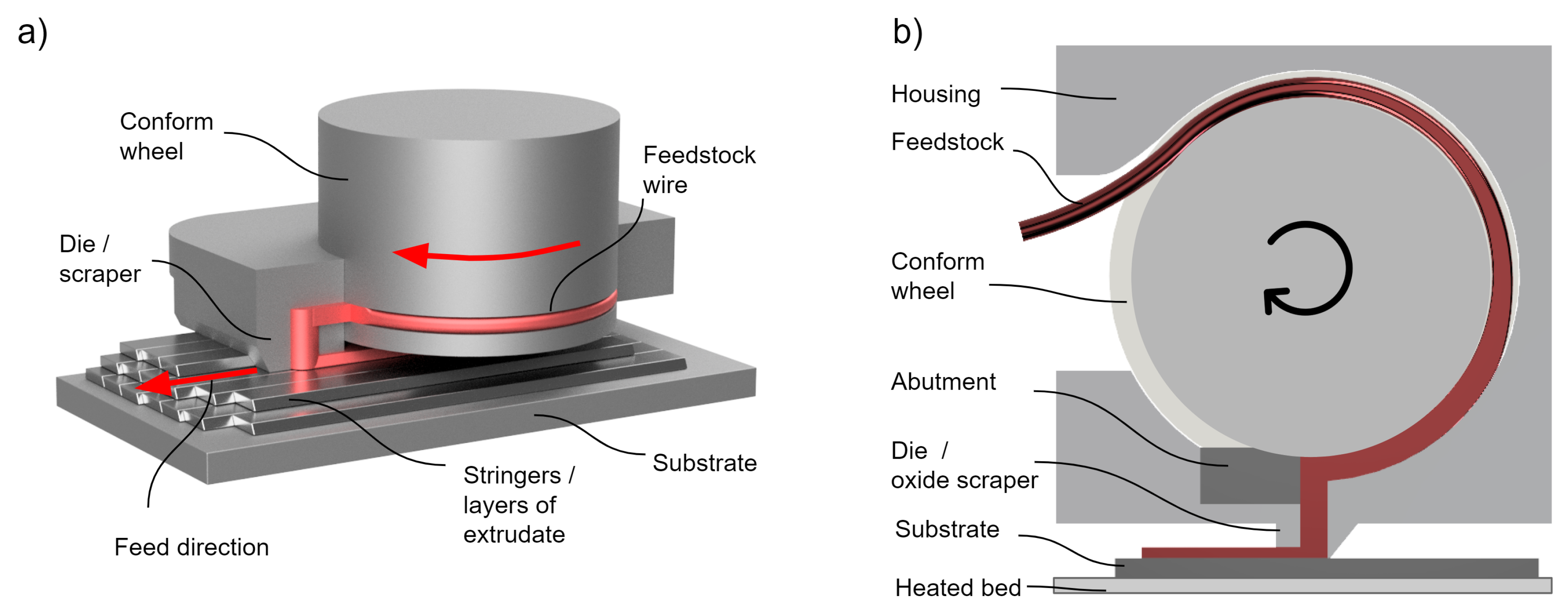
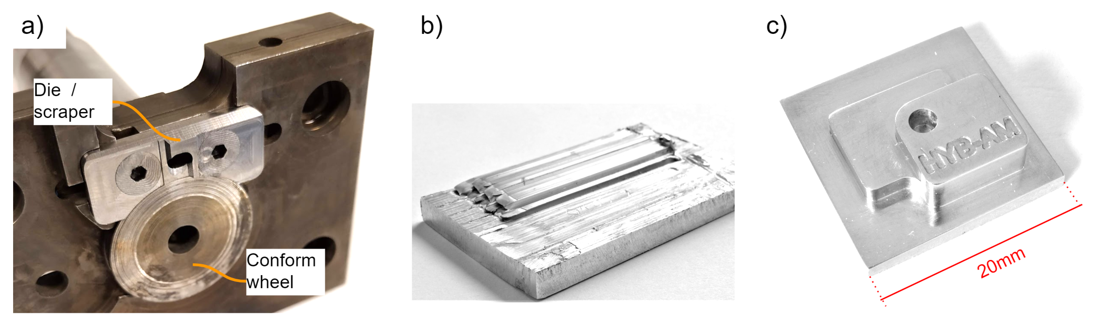
2. The HYB-AM Process
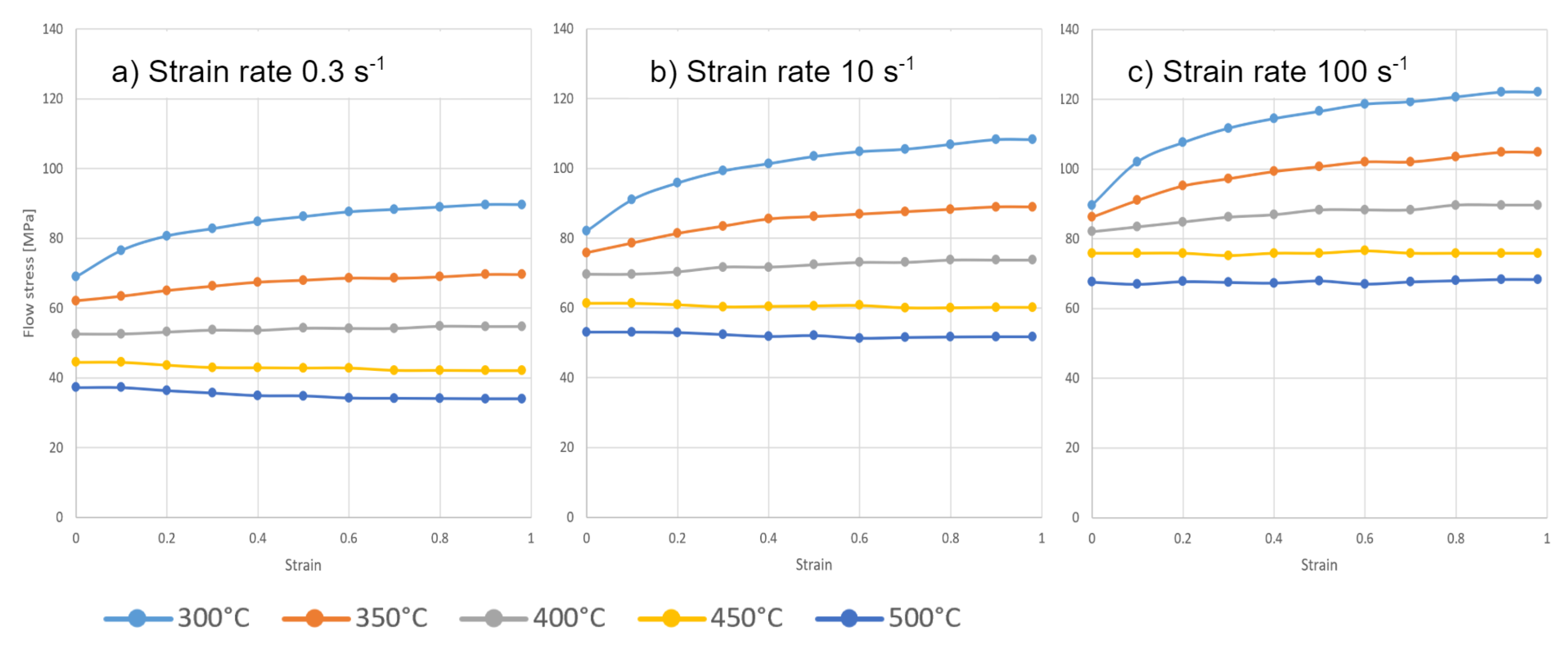
3. Materials and Methods
3.1. FEM-Models
3.2. Model 1: Extrusion Pressure Generating Mechanism
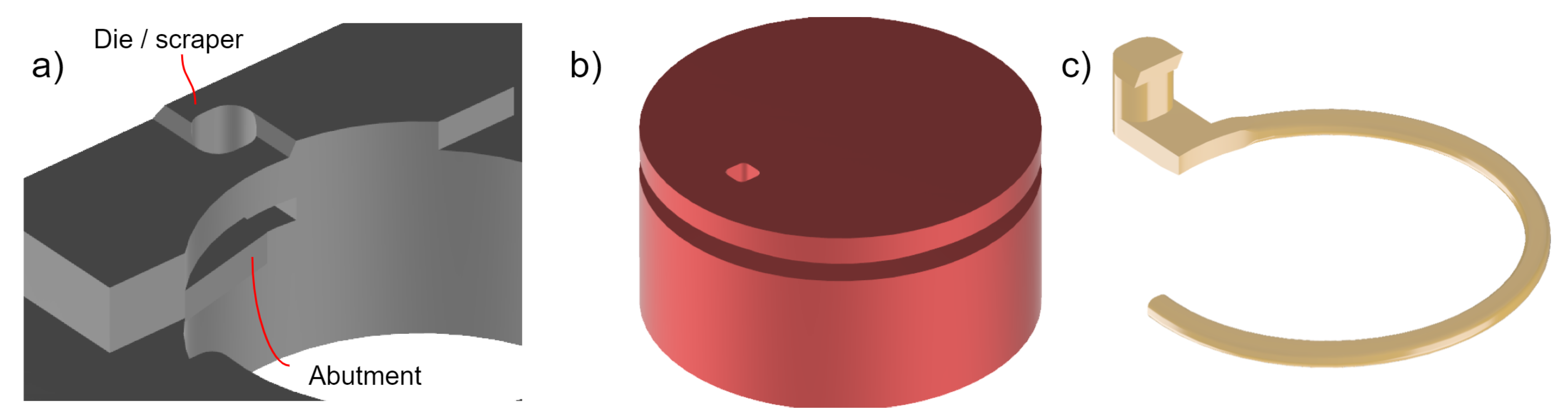
3.3. Model 2: Stringer Deposition Sequence
4. Results
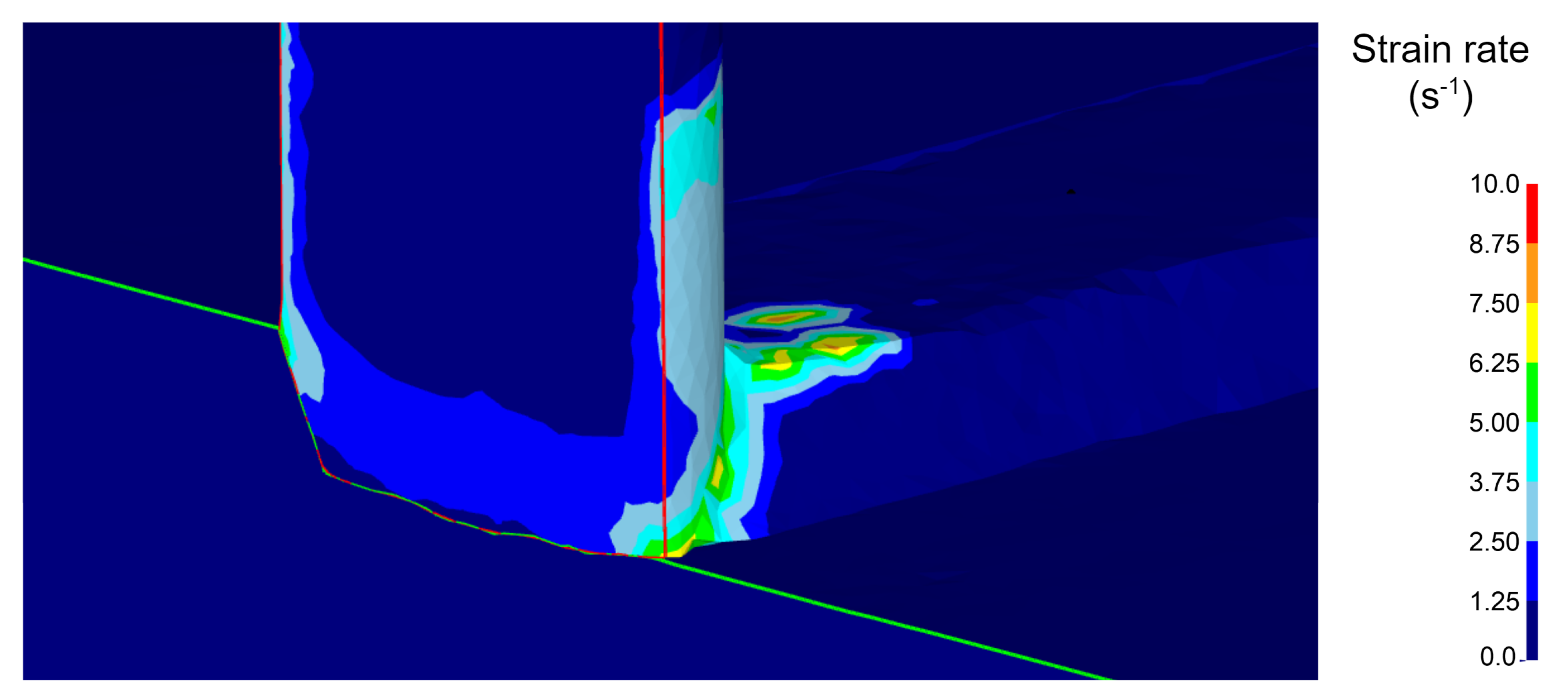
4.1. Model 1
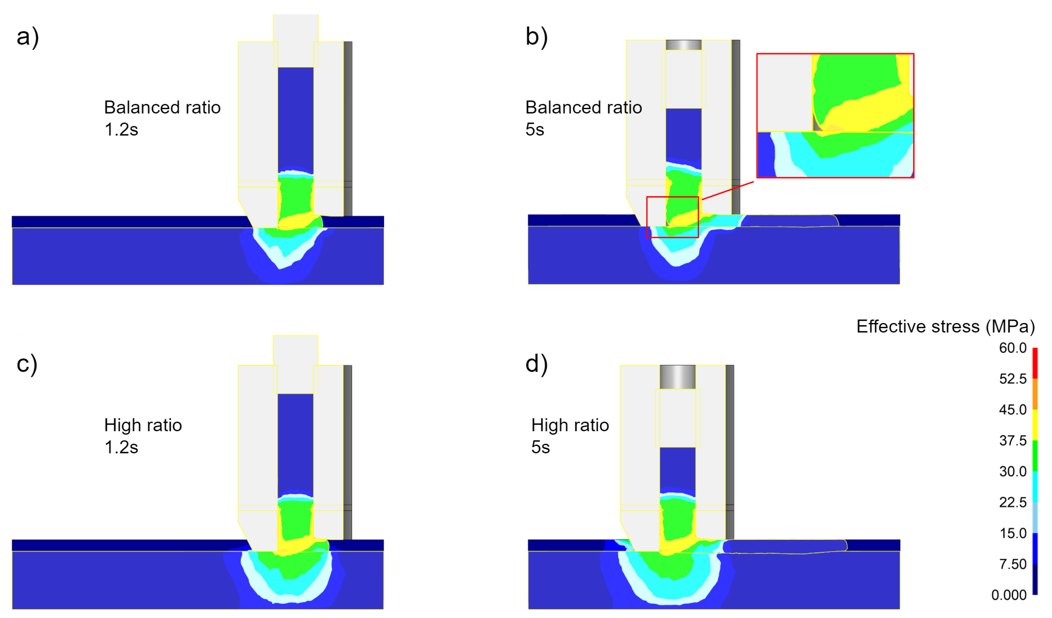
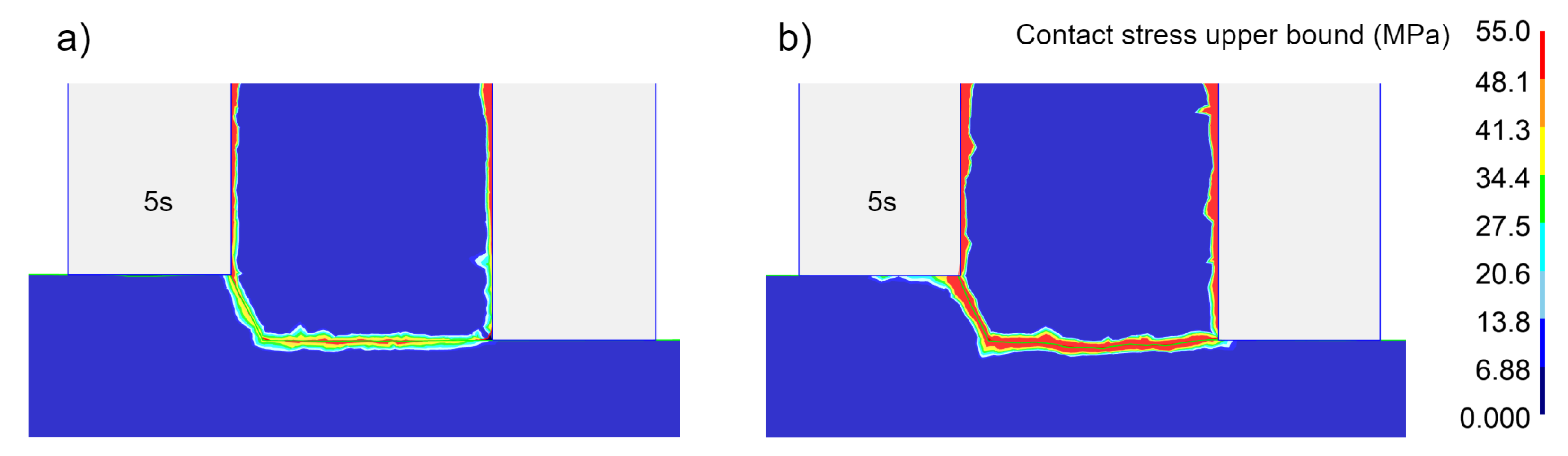
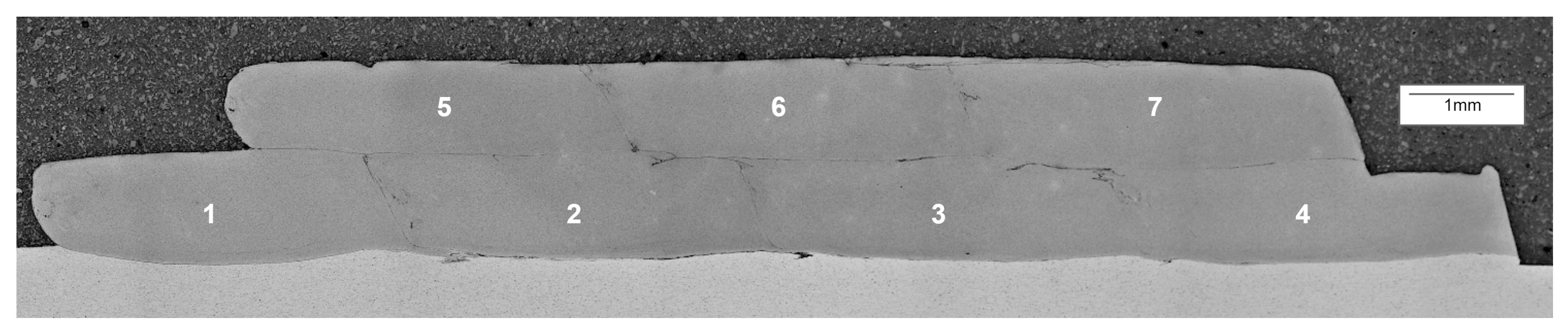
4.2. Model 2
5. Discussion
6. Conclusions
- 1.
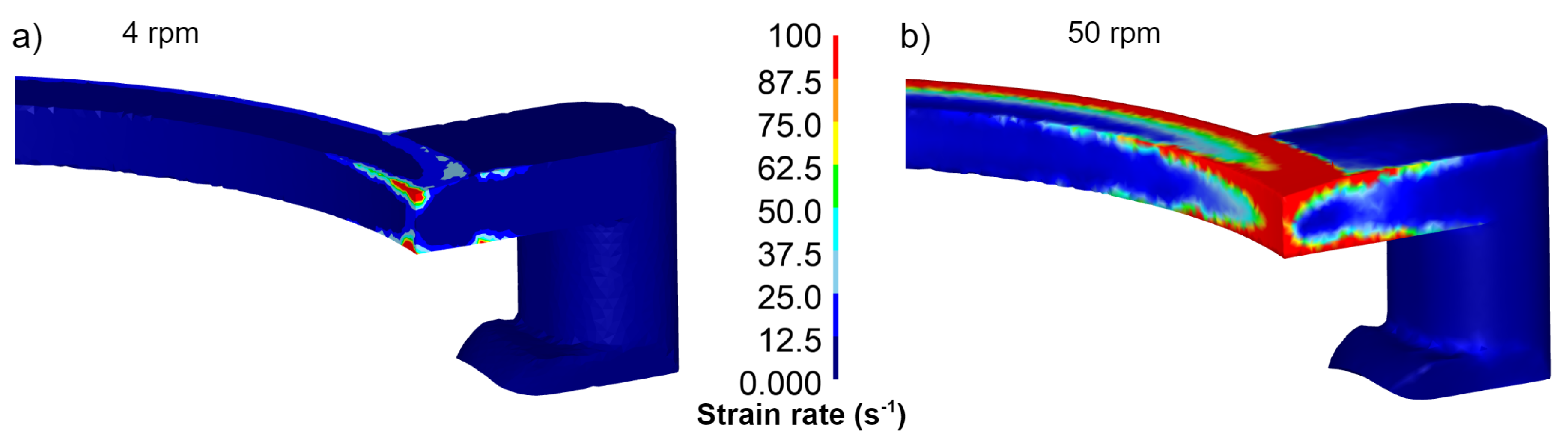
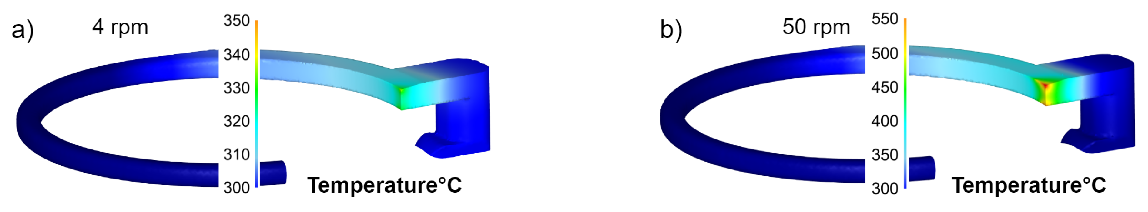
- Increased angular velocity of the wheel both increases the strain rates and the heat generation due to the higher deformation work.
- 2.
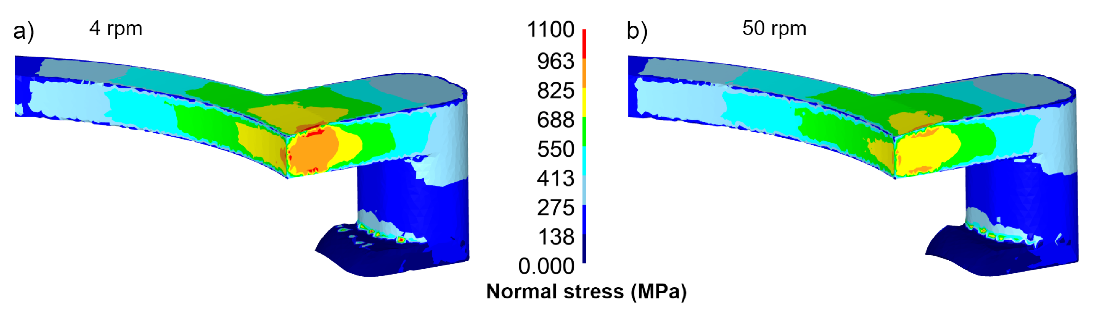
- The simulations show that the contact pressure inside the plastic zone is virtually similar at 4 RPM and 50 RPM. For the current design, the maximum deposition rate will be 1 kg/h when the extruder, as well as the substrate material, is pre-heated to C.
- 3.
- The length of the extrusion grip zone is not affected by an increased deposition rate.
- 4.
- In order to obtain sufficient contact pressure for bonding to occur across the full stringer width, the input flow rate needs to be higher than the actual flow out of the rear opening of the die.
- 5.
- When the feed speed becomes too high relative to the material flow through the die, a gas pocket is formed in the outlet. This gas pocket can cause oxidation of the scraped surface with reduced bonding quality as a consequence.
Author Contributions
Funding
Acknowledgments
Conflicts of Interest
Abbreviations
| AM | Additive Manufacturing |
| CRE | Continuous Rotary Extrusion |
| FEM | Finite Element Method |
| FEA | Finite Element Analysis |
References
- Blindheim, J.; Grong, Ø.; Aakenes, U.R.; Welo, T.; Steinert, M. Hybrid Metal Extrusion & Bonding (HYB)—A new technology for solid-state additive manufacturing of aluminium components. Procedia Manuf. 2018, 26, 782–789. [Google Scholar] [CrossRef]
- Blindheim, J.; Welo, T.; Steinert, M. Rapid prototyping and physical modelling in the development of a new additive manufacturing process for aluminium alloys. Procedia Manuf. 2019, 34, 489–496. [Google Scholar] [CrossRef]
- Blindheim, J.; Welo, T.; Steinert, M. First demonstration of a new additive manufacturing process based on metal extrusion and solid-state bonding. Int. J. Adv. Manuf. Tech. 2019. under review. [Google Scholar]
- Blindheim, J.; Grong, Ø.; Welo, T.; Steinert, M. On the mechanical integrity of AA6082 3D structures deposited by hybrid metal extrusion & bonding additive manufacturing. J. Mater. Process. Technol. 2019. under review. [Google Scholar]
- Green, D. Continuous extrusion-forming of wire sections. J. INST MET 1972, 100, 295–300. [Google Scholar]
- Etherington, C. Conform—A new concept for the continuous extrusion forming of metals. J. Eng. Ind. 1974, 96, 893–900. [Google Scholar] [CrossRef]
- Song, L.; Yuan, Y.; Yin, Z. Microstructural Evolution in Cu-Mg Alloy Processed by Conform. Int. J. Nonferrous Metall. 2013, 2, 100–105. [Google Scholar] [CrossRef][Green Version]
- Thomas, B.M.; Derguti, F.; Jackson, M. Continuous extrusion of a commercially pure titanium powder via the Conform process. Mater. Sci. Technol. 2017, 33, 899–903. [Google Scholar] [CrossRef]
- Mitka, M.; Misiolek, W.Z.; Lech-Grega, M.; Gawlik, M.; Bigaj, M.; Szymanski, W. Continuous rotary extrusion of magnesium alloy AZ 91. In Proceedings of the Conference: Materials Science & Technology 2015, Columbus, OH, USA, 4–8 October 2015; p. 7. [Google Scholar]
- Mitka, M.; Gawlik, M.; Bigaj, M.; Szymanski, W. Continuous Rotary Extrusion (CRE) of Flat Sections from 6063 Alloy. Key Eng. Mater. 2015, 641, 183–189. [Google Scholar] [CrossRef]
- Ji, X.; Zhang, H.; Luo, S.; Jiang, F.; Fu, D. Microstructures and properties of Al–Mg–SI alloy overhead conductor by horizontal continuous casting and continuous extrusion forming process. Mater. Sci. Eng. A 2016, 649, 128–134. [Google Scholar] [CrossRef]
- Kim, Y.H.; Cho, J.R.; Jeong, H.S.; Kim, K.S.; Yoon, S.S. A study on optimal design for CONFORM process. J. Mater. Process. Technol. 1998, 80, 671–675. [Google Scholar] [CrossRef]
- Hodek, J.; Zemko, M. FEM Model of Continuous Extrusion of Titanium in DEFORM Software. In Proceedings of the 2nd International Conference on Recent Trends in Structural Materials, Parkhotel Plzen, Czech Republic, 21–22 November 2012; p. 7. Available online: http://comat2014.tanger.cz/files/proceedings/11/reports/1326.pdf (accessed on 5 May 2019).
- Valberg, H.; Rajendran, N.; Misiolek, W. The Mechanics of the Continuous Rotary Extrusion Process Investigated by FEM analysis. In Proceedings of the Eighth International Conference On Advances in Mechanical, Aeronautical and Production Techniques-MAPT 2018, Kuala Lumpur, Malaysia, 3–4 February 2018; pp. 1–7. [Google Scholar] [CrossRef]
- Rajendran, N.; Valberg, H.; Misiolek, W.Z. The FEM simulation of continuous rotary extrusion (CRE) of aluminum alloy AA3003. Aip Conf. Proc. 2017, 050004. [Google Scholar] [CrossRef]
- Rajendran, N.; Mitka, M.; Lech-Grega, M.; Misiolek, W.Z. Effect of tool geometry on the velocity and strain rate fields in continuous rotary extrusion of magnesium AZ91 alloy. Procedia Manuf. 2018, 15, 264–271. [Google Scholar] [CrossRef]
- Akeret, R. Extrusion welds-quality aspects are now center stage. In Proceedings of the 5th International Aluminium Extrusion Technology Seminar, Chicago, IL, USA, 19–22 May 1992. [Google Scholar]
- Valberg, H. Extrusion welding in aluminium extrusion. Int. J. Mater. Prod. Technol. 2002, 17, 497–556. [Google Scholar] [CrossRef]
- Yu, J.; Zhao, G. Interfacial structure and bonding mechanism of weld seams during porthole die extrusion of aluminum alloy profiles. Mater. Charact. 2018, 138, 56–66. [Google Scholar] [CrossRef]
- Yu, J.; Zhao, G.; Chen, L. Analysis of longitudinal weld seam defects and investigation of solid-state bonding criteria in porthole die extrusion process of aluminum alloy profiles. J. Mater. Process. Technol. 2016, 237, 31–47. [Google Scholar] [CrossRef]
- Heinemann, H. Flow Stress of Different Aluminum and Copper Alloys for High Strain Rates and Temperature. Ph.D. Thesis, TH Aachen, Aachen, Germany, 1961. [Google Scholar]
- Valberg, H.S. Applied Metal Forming; Cambridge University Press: Cambridge, UK, 2006. [Google Scholar]


| Parameter | Parameter | Value |
|---|---|---|
| General | Pin diameter | 28 mm |
| Feedstock wire diameter | 1.6 mm | |
| Heat transfer coefficient feedstock/tooling | 11(N/s)/(mm/c) | |
| Simulation type | Lagrangian Deformation & Heat transfer | |
| Mesh type | Tetrahedral | |
| House | Initial temperature | C |
| Material | AISI-H13 | |
| Friction factor against feedstock, m | 2 | |
| Initial mesh elements/nodes | 48,031/10,844 | |
| Mesh refinement in plastic zone | 0.07 | |
| Mesh refinement die | 0.25 | |
| Wheel | Initial temperature | C |
| Material | AISI-H13 | |
| Friction factor against feedstock, m | 2 | |
| Initial mesh elements/nodes | 29,690/6734 | |
| Mesh refinement in plastic zone | 0.1 | |
| Rotational speed | 4 RPM/50 RPM | |
| Feedstock | Initial temperature | C |
| Material | AA6082 | |
| Initial mesh elements/nodes | 124,837/28,375 | |
| Mesh refinement in plastic zone | 0.5 | |
| Friction factor against feedstock, m | 2 | |
| Substrate | Initial temperature | C |
| Material | AISI-H13 | |
| Friction factor against feedstock, m | 0 |
| Parameter | Parameter | Value |
|---|---|---|
| General | Simulation type | Lagrangian Deformation |
| Mesh type | Tetrahedral | |
| Feedstock | Material | AA6082 |
| Temperature | C | |
| Initial mesh elements/nodes | 33,261/7379 | |
| Mesh refinement | 0.2 | |
| Substrate | Material | AA6082 |
| Temperature | C | |
| Initial mesh elements/nodes | 79,710/17,714 | |
| Mesh refinement | 0.35 | |
| Contact condition feedstock | non-separable | |
| Friction factor against feedstock, m | 2 | |
| Die | Friction factor against feedstock, m | 2 |
| Friction factor substrate, m | 0 | |
| Inlet cross-section area | 10.5 mm | |
| Outlet cross-section area | 3.5 mm | |
| Ram | Speed, Balanced/High | 1.0/1.2 mm/s |
| Container | Friction factor against feedstock, m | 0 |
| Bed | Friction factor substrate, m | 2 |
| Feed delay | 1 s | |
| Speed in feed direction | 3.0 mm/s |
© 2019 by the authors. Licensee MDPI, Basel, Switzerland. This article is an open access article distributed under the terms and conditions of the Creative Commons Attribution (CC BY) license (http://creativecommons.org/licenses/by/4.0/).
Share and Cite
Blindheim, J.; Welo, T.; Steinert, M. Investigating the Mechanics of Hybrid Metal Extrusion and Bonding Additive Manufacturing by FEA. Metals 2019, 9, 811. https://doi.org/10.3390/met9080811
Blindheim J, Welo T, Steinert M. Investigating the Mechanics of Hybrid Metal Extrusion and Bonding Additive Manufacturing by FEA. Metals. 2019; 9(8):811. https://doi.org/10.3390/met9080811
Chicago/Turabian StyleBlindheim, Jørgen, Torgeir Welo, and Martin Steinert. 2019. "Investigating the Mechanics of Hybrid Metal Extrusion and Bonding Additive Manufacturing by FEA" Metals 9, no. 8: 811. https://doi.org/10.3390/met9080811
APA StyleBlindheim, J., Welo, T., & Steinert, M. (2019). Investigating the Mechanics of Hybrid Metal Extrusion and Bonding Additive Manufacturing by FEA. Metals, 9(8), 811. https://doi.org/10.3390/met9080811