Article

Root Cause Analysis of Surface Cracks in Heavy Steel Plates during the Hot Rolling Process

by
Abbas Bahrami
1,
Mahdi Kiani Khouzani
1,
Seyed Amirmohammad Mokhtari
1,
Shahin Zareh
2 and
Maryam Yazdan Mehr
3,*
1
Department of Materials Engineering, Isfahan University of Technology, Isfahan 84156-83111, Iran
2
Hormozgan Steel Company (HOSCO), Bandar Abbas, Iran
3
EEMCS Faculty, Delft University of Technology, Mekelweg 4, 2628 CD Delft, The Netherlands
*
Author to whom correspondence should be addressed.
Metals 2019, 9(7), 801; https://doi.org/10.3390/met9070801
Submission received: 7 July 2019 / Revised: 16 July 2019 / Accepted: 19 July 2019 / Published: 20 July 2019
(This article belongs to the Special Issue Rolling of Metals)

Abstract

:
This paper investigates the root cause of the formation of surface cracks on hot-rolled C–Mn constructional steel heavy plates. Cracks are rather evenly distributed over the surface in the form of colonies of cracks. Samples were cut from the heavy plate. The microstructure of samples in the as-cast and hot-rolled states were studied using optical and electron microscopes as well as energy dispersive X-ray spectroscopy (EDS). Results show that cracks are heavily oxidized. De-carburized areas are also seen alongside cracks. The crack tip is in the form of a deer-horn, indicating that crack branching has taken place during deformation. The crack initiation sites are V-shaped grooves on the surface of as-cast slabs. Correlations between microstructures, processing parameters, and crack formation are discussed.

1. Introduction

Lately, requests for high quality C–Mn steel heavy plates have been increasing in the oil and gas industries as well as structural applications due to increased demands in these industries. Heavy plates, made by continuous casting and hot rolling, are widely used in many industries. Defects, associated with heavy plates, can be categorized into internal and external defects. Both could have negative implications for the sound performance of final products. The latter ones are more sensitive in the sense that they are exposed to air and it is likely they get oxidized. Surface defects can further grow during rolling, resulting in the deterioration of the quality of products. Figure 1 shows schematic representation of typical surface defects in slabs and rolled plates [1,2,3].
The upside of surface defects, compared to internal ones, is that the chance that they can be visually detected and identified during quality control is high [4]. Depending on the depth of surface irregularities on the surface of heavy plates, they might be rejected, which is considered as a major economic loss for a plant. Alternatively, a heavy plate containing surface defects might be downgraded due to poor surface quality and poor surface appearance. Thus, one of the most important objectives of a hot rolling plant is minimizing heavy plates with surface defects and discontinuities. There are different types of surface defects [5,6,7,8,9,10,11,12,13,14], with many of them having to do with the poor quality of steel during continuous casting [15,16,17]. Other important stages following continuous casting are reheating and hot rolling. There is always a chance that surface defects after casting are either very small or not detected. These defects will extend and show up in the later stages, i.e., during reheating or rolling [8]. Complete eradication of surface defects in heavy plates necessitates a complete understanding of root causes of all kinds of surface defects. This way steel manufacturers can minimize the frequency and the extent of surface flaws in heavy plates. Current tough worldwide competition and set requirements from customers leave no option for heavy plate manufacturers but to keep defected products at the lowest level. This paper investigates a type of surface defect in C–Mn steel heavy plates. To our knowledge, this is not well documented and investigated so far. This paper will comprehensively introduce this defect and will discuss possible root causes of the formation of this type of defect. The paper ends with some recommendations to minimize this defect in heavy plates.

2. Background

Surface cracks in this case are related to heavy plates of 30 cm thickness with average chemical composition 0.16 C-1.20 Mn-0.022 P-0.02 S-0.257 Si-0.045 Al-Fe (Bal.) (wt. %). Original slabs were made by continuous casting. Slabs were pre-heated at approximately 1250 °C up to 4 h, and were hot rolled to the final thickness of the heavy plate (30 cm) after approximately 16 passes in a reverse mill. Figure 2 shows the visual appearance of surface cracks on the heavy plate. Cracks are scattered all over the surface. There is no indication that cracks are more frequent at the side or the centre of plates. Spots, shown in Figure 2, are colonies of accumulated smaller cracks. The size of these crack colonies range from 5 to 30 cm. Cracks are all oriented along rolling direction. The depth of observed surface flaws in some cases are so high that plates are inevitably returned to the casting unit. In some cases, surface cracks can be eliminated by surface grinding. This causes major trouble in the rolling company, in the sense that these cracks need to be removed by grinding of the surface, which necessitates spending a lot of time as well as performing double inspection (one before grinding and the other one after grinding). This work aims at investigating the root cause of the problem.

3. Experimental

Samples were cut from the heavy-plate, as shown in Figure 2. The plate of interest was initially visually checked and colonies of cracks were marked. Samples for microscopy and fractography were cut from the plate using electro discharge machining (EDM). For metallography, samples were prepared by grinding the surface with 80 to 2400 grinding papers, followed by polishing with diamond paste (3 and 1 μm). The microstructure of samples was studied in both as-polished and after etching. Etching was performed with Nital 2% solution. The crack surface and microstructure was studied by means of a scanning electron microscope (SEM) and energy dispersive X-ray spectroscopy (EDS). Vickers hardness measurements were performed with 30 kg loads on a line across a crack.

4. Results and Discussion

4.1. Microstructure of As-Received Slabs (before Hot Rolling)

Figure 3 shows a SEM image of the typical ferritic–pearlitic microstructure of heavy plates in the bulk and surface of slabs (before hot rolling). There were not many inclusions found in the microstructure, inferring that the quality of the alloy in terms of secondary oxide/sulphide particles was overall very good. Typical features at the surface of the slab were surface V-notches, as marked in Figure 3a. These V-notches have depth in the order of a few tens of micro meters and are filled with surface oxide scales/phases. V-shaped grooves are possibly formed because of oscillation during the casting stage. Oscillation marks are a normal surface feature in continuously cast slabs. They periodically form at the meniscus because of mold oscillation. Yet, in case of improper control, the depth of these oscillation marks can increase to levels that they act as crack initiation sites [17,18].

4.2. Microstructure of Heavy Plates

Figure 4 represents an elemental line scan on top of a crack. As can be seen in this figure, the concentration of oxygen at the crack is significantly higher than that in the vicinity of cracks, inferring that the crack is filled with an iron oxide phase.
Figure 5 shows SEM images of a crack at the surface. It appears that the crack is formed due to the breakage of the oxide layer on the surface. Some rounded particles are also observed inside cracks and in areas in the vicinity of the cracks with their sizes ranging from a few microns up to 30 microns. Three different features were analyzed using EDS, i.e., the surface, as shown in Figure 5a, rounded white particles, as shown in Figure 5b, and small particles inside cracks, as shown in Figure 5c. Results of EDS analyses indicate that rounded particles are either iron oxide particles or molybdenum-rich particles. Small molybdenum-rich particles are only in small percentages of rounded particles inside cracks. Most particles inside cracks are iron oxide particles. Given that the starting material is not expected to contain any molybdenum, and as molybdenum is not added to the melt, the only option left for the origin of these molybdenum-rich particles must be residues from the processing.
Figure 6 reveals optical microscope images of the microstructure around the crack. There are several features worth mentioning. First of all, the crack is completely filled with an iron oxide phase. The presence of this oxidizing environment inside the crack results in de-carburization in the vicinity of cracks, in such a way that there is a band of fully de-carburized ferritic microstructure alongside the crack. The microstructure of the steel away from the crack is ferritic–pearlitic as commonly observed in plain carbon steel plates. Other than this de-carburized layer, there is no other microstructural abnormality, like excessive grain coarsening or deformed/elongated grains in either side of the surface crack.
The carbon concentration profile across the crack can be obtained from the following equation, assuming semi-infinite conditions [19]:
C ( x ,   t ) = C 0 ( C S C 0 )   erf   ( x / 2 D t )
where CS is the carbon concentration inside the crack (taken to be equal to zero, due to high oxygen activity inside the crack), C0 is carbon content of the alloy, t is the rolling time, and D is the diffusion equation of carbon in austenite iron, obtained from the following equation:
D = D 0 exp ( Q / R T )
where D0 = 2.3 × 10⁻⁵ m2/s, Q = 148 kJ/mol, and R = 8.314 J/mol·K [20]. An average value of 1100 °C was assumed for the rolling temperature. Figure 7 shows the contour of carbon diffusion across the crack. Results show that after 16 passes carbon is heavily depleted in approximately 300–400 μm distance from the crack. It is also seen that with increasing pass numbers, the depletion layer gets wider. According to Fe-C diagram, pearlite is not expected to form in carbon content less than 0.008 wt. %. Results of this calculation is very well in accordance with the experimental results.
Observed cracks in most cases consist of two distinctive features; firstly, cracks are all nucleated on V-notches. The other characteristic feature is that cracks end up in a deer-horn-type branching at the end. This kind of crack branching is reported to be due to the deformation during hot rolling [8].
Figure 8 shows other examples of deer-horn crack end branching. It appears that surface cracks are initiated at the tip of V-grooves and are propagated during differential loading. The crack propagation path is initially straight in the sense it does not seem that crack is following the grain boundary path. The last stages of rolling are associated with crack branching. The cracks must have developed in the initial rolling stages and branched during the subsequent rolling passes. There are many influencing factors that might result in surface cracking on hot-rolled steel heavy plates [10]. Defects of the surface are due to different reasons, but generally they are confined into two main categories: (1) primary defects existed on continuous casting process slabs which propagate or are inherited from defects generated by rolling processes and are originated from upstream rolling processes defects and (2) also these defects can occur because of incorrect rolling technologies and foreign bodies were unevenly rolled in the interface of the strip rolled [6]. In this case the origin of cracks is certainly V-notches. Any mitigation strategy needs to address this problem by trying to eliminate these V-grooves at the surface. Surface notch V-grooves have a very sharp end which obviously is a place where stress intensity goes up and this in turn results in the crack initiation and propagation.
Figure 9 shows the fracture surface of the sample, taken from the surface of heavy plates, containing cracks. The fracture is typically transgranular in nature. As well, one can see de-cohesions and discontinuities at the fracture surface, which are due to the presence of surface cracks in the sample.
Figure 10 shows a typical hardness profilometry across the crack. As can be seen in this figure, the hardness at the center of the crack, where the oxide layer is present, has significantly increased. This is not surprising, since the layer inside the crack is heavily oxidized. Areas in close proximity to the oxide layer are clearly the weakest spots, which obviously has to do with the fact that the microstructure at the vicinity of the cracks is ferritic.

5. Concluding Remarks

This paper studies surface cracking in carbon steel heavy plates after hot rolling. These cracks have several characteristic features, given here:
(1)
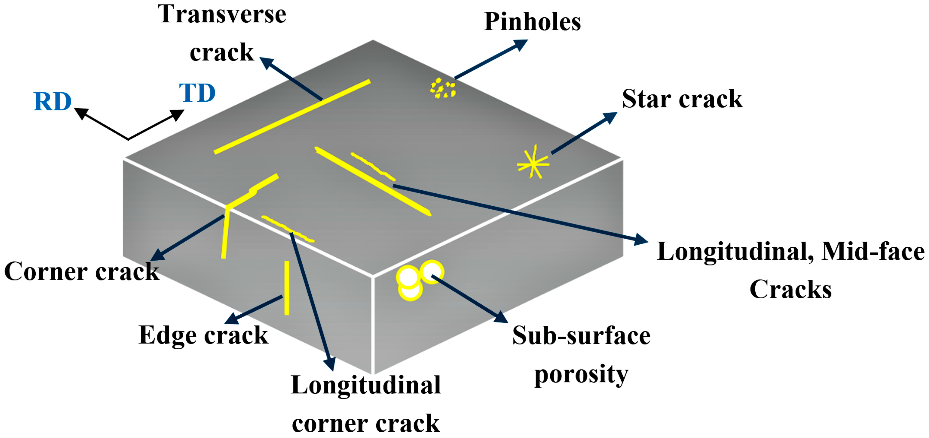
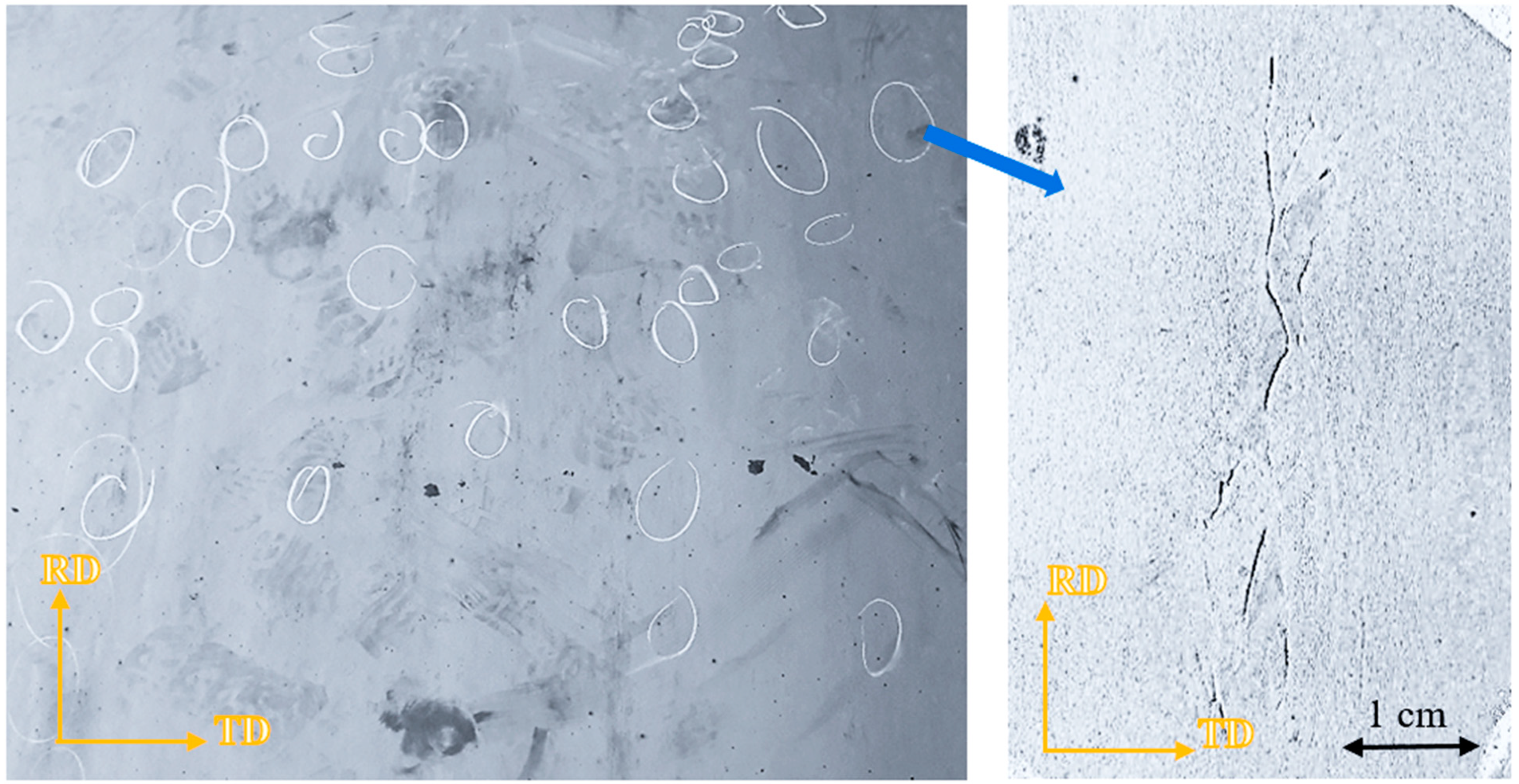
Cracks are evenly distributed all over the surface of heavy plates and are oriented in the rolling direction.
(2)
Cracks are more accumulated in isolated colonies, with their sizes ranging from a few centimetres to a few tens of centimetres. The depths of cracks are up to a few hundred micrometres.
(3)
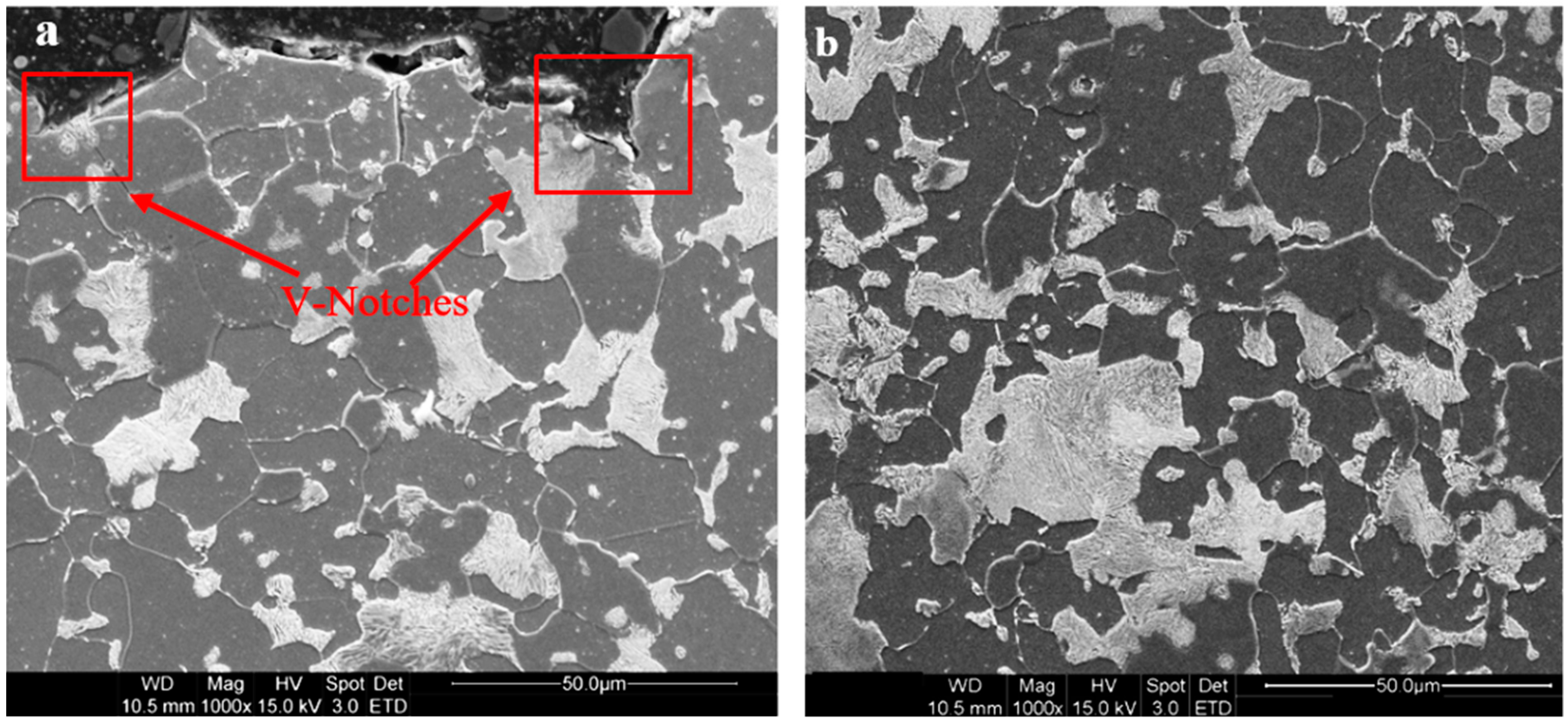
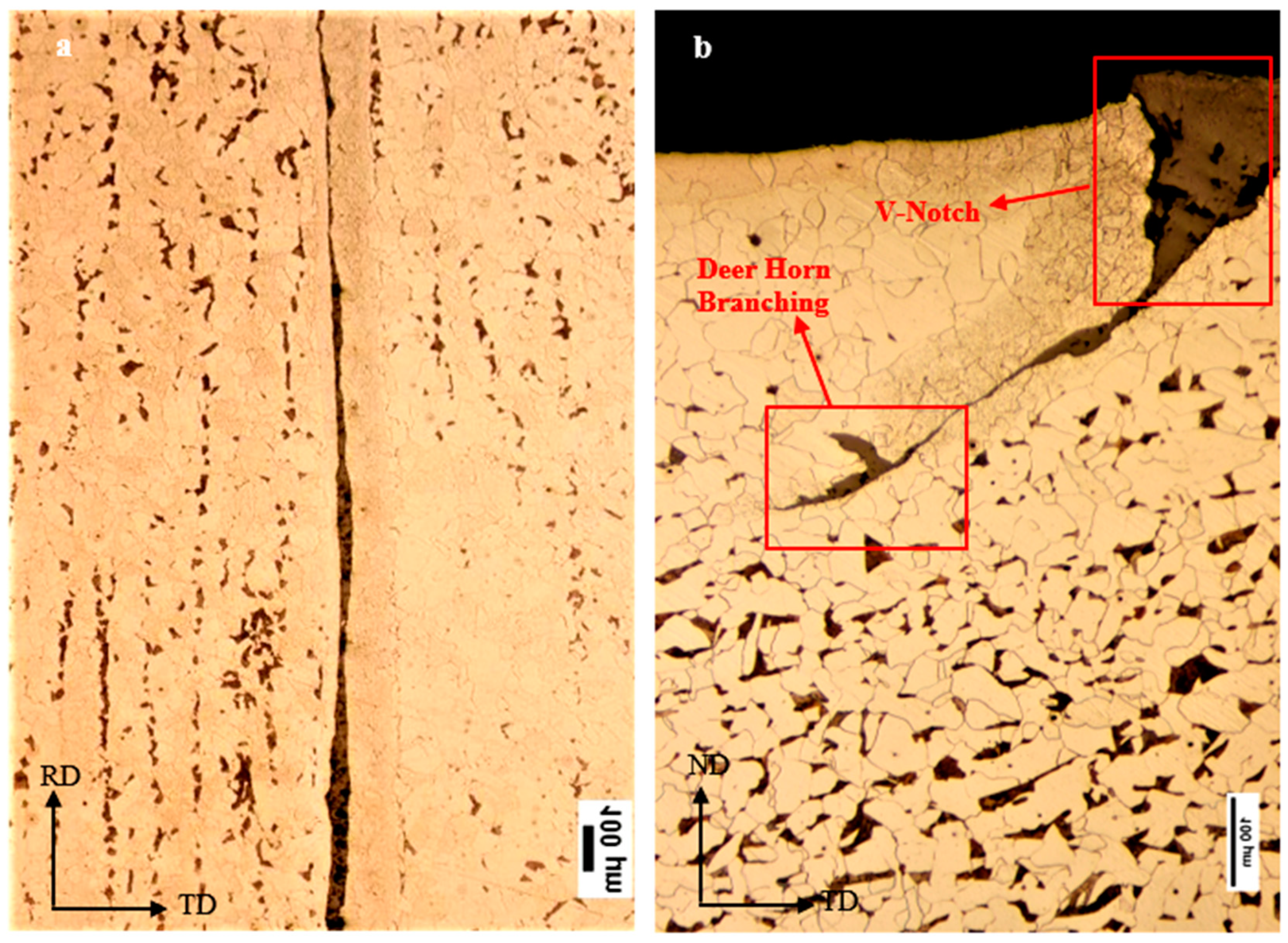
Cracks are nucleated at the tip of V-notches, existing at the surface of slabs.
(4)
Cracks end up in deer-horn branching.
(5)
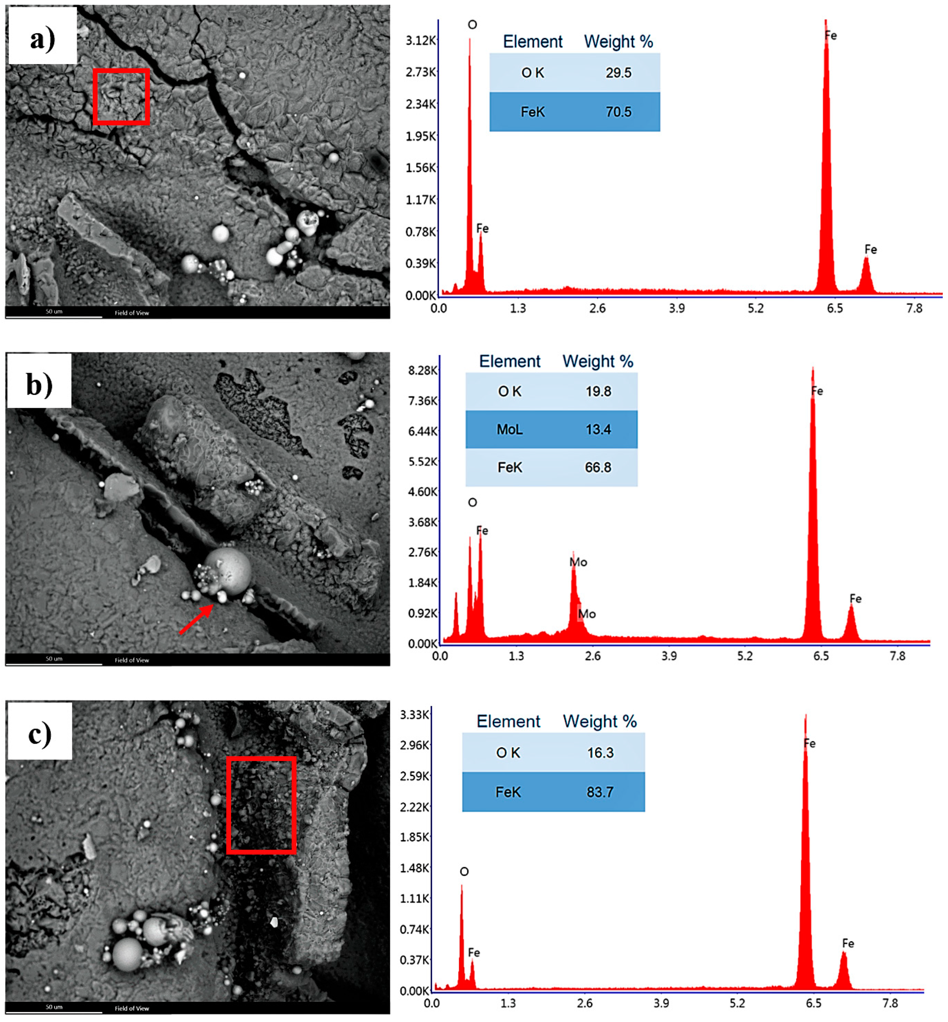
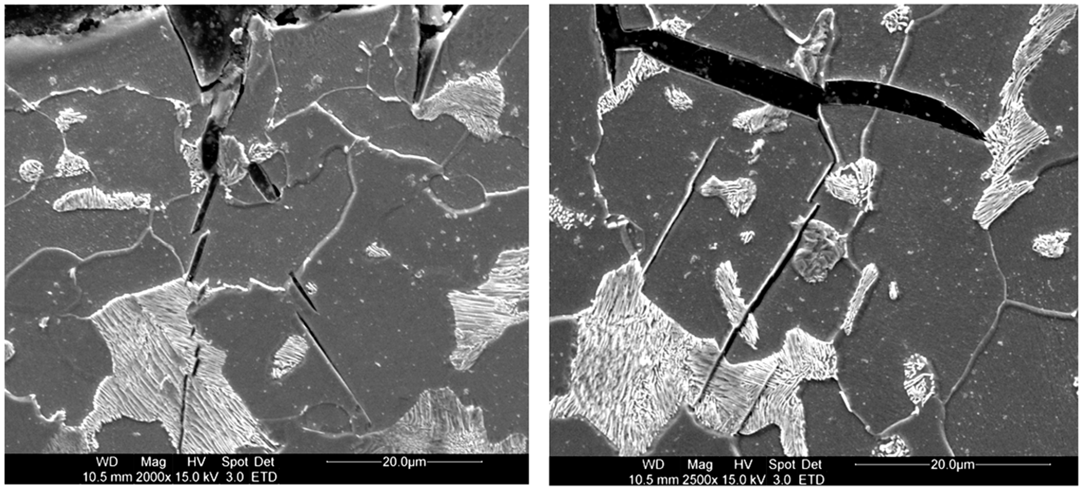
In most cases cracks are fully filled with an iron oxide.
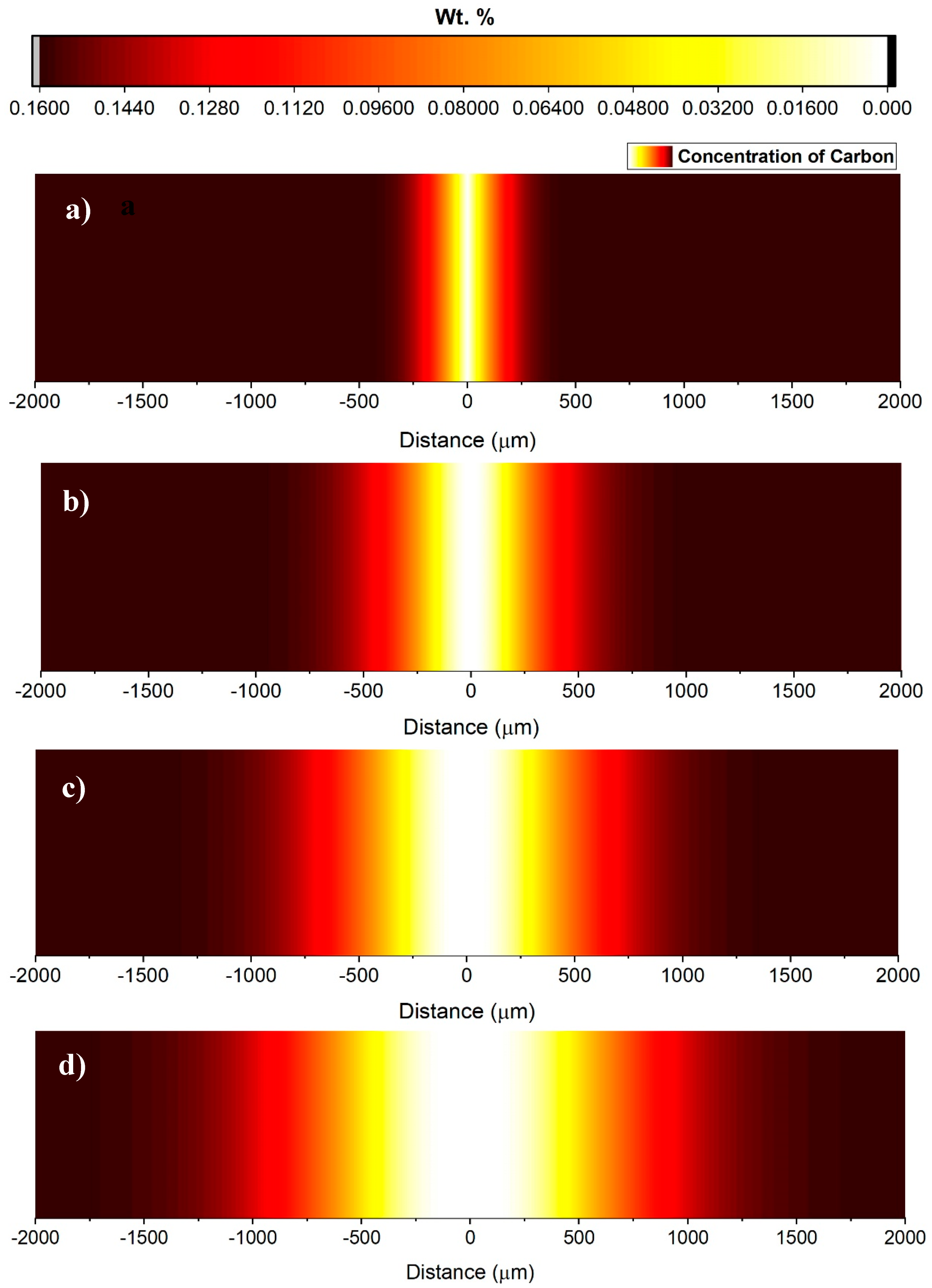
(6)
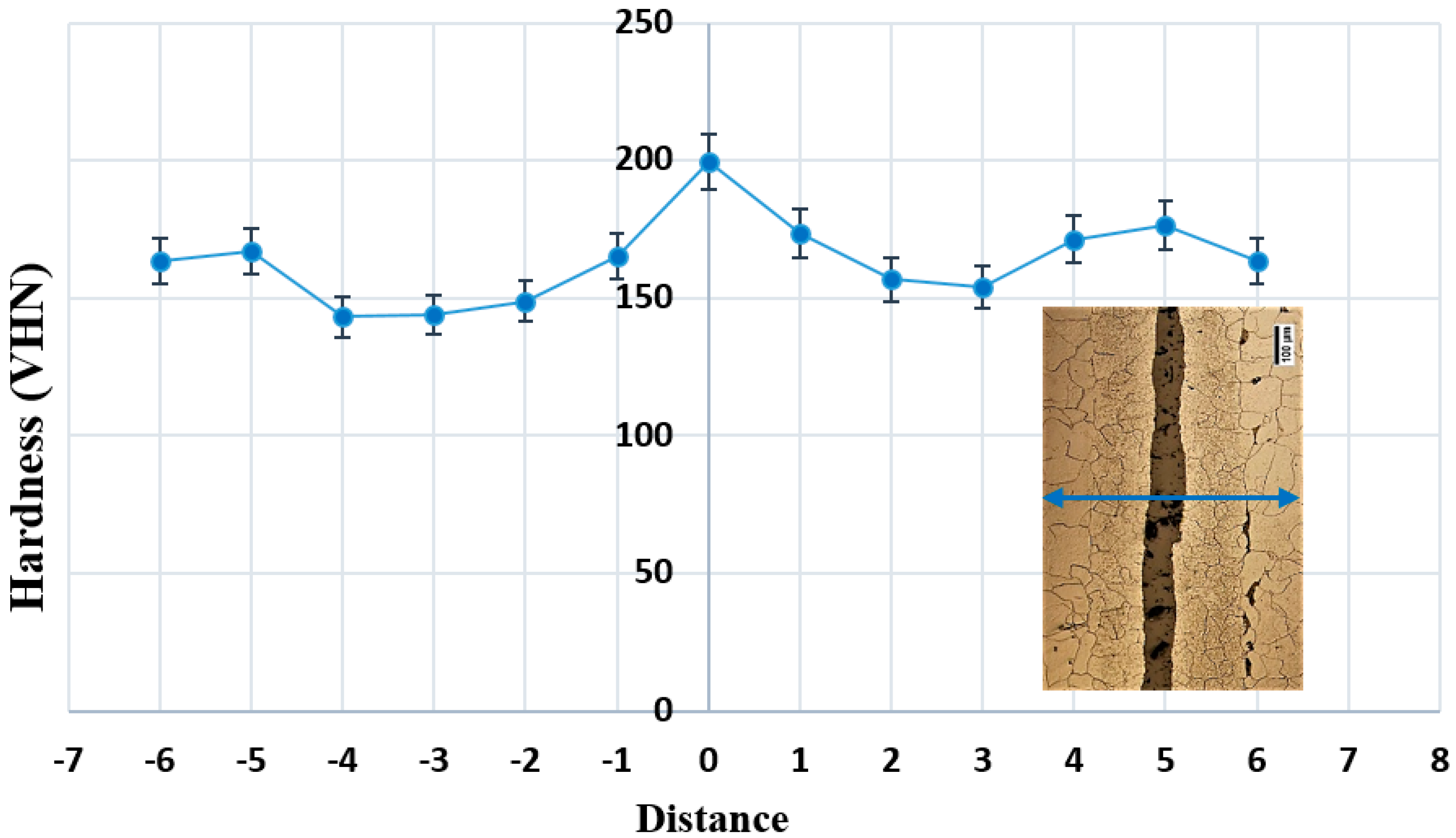
The area at the vicinity of cracks are heavily de-carburized, in such a way that in most cases the structure adjacent to the crack is fully ferritic.
(7)
Cracking in this case has nothing to do with the chemistry of the alloy and inclusions.
To solve this problem, one needs to minimize the formation of surface V-grooves, given that these surface irregularities are spots, where cracks can nucleate. Presence of the oxide phase inside the crack is possibly to do with an improper pre-heating atmosphere. In case the oxygen/gas ratio in the pre-heating stage is not optimized, free excess oxygen can enter into surface notches and this results in the formation of an iron oxide phase inside cracks. The oxide phase is in nature a brittle phase which cannot accommodate plastic deformation. Besides, oxidization inside cracks is associated with de-carburization of the alloy in the vicinity of the cracks. In the worst case condition, this will result in a fully ferritic microstructure adjacent to the crack. This means that the area close to the crack is comparatively softer and undergoes a higher degree of deformation, which in turn has implications for crack propagation. One way to tackle this problem is therefore trying to minimize oxidation during reheating. During reheating of the slab before rolling, oxygen present in the reheating furnace diffuses through the crack opening and reacts with the carbon of the steel, resulting in partial decarburization around the crack. Decreasing the oxygen/gas ratio in reheating furnaces could have a key positive impact.

Author Contributions

Conceptualization, M.K.K. and A.B.; methodology, M.K.K. and S.A.M.; formal analysis, A.B. and M.K.K.; investigation, M.K.K. and S.A.M.; writing—original draft preparation, M.K.K.; writing—review and editing, A.B. and M.Y.M.; visualization, M.K.K.; supervision, A.B., S.Z. and M.Y.M.; project administration, M.Y.M.

Funding

This research received no external funding.

Acknowledgments

Authors would like to thank Delft University of Technology for support in publishing this manuscript.

Conflicts of Interest

The authors declare no conflict of interest.

References

  1. BrimacombeK, J.K.; Sorimachi, K. Crack formation in the continuous casting of steel. Metall. Trans. B 1977, 8, 489–505. [Google Scholar] [CrossRef]
  2. Veitch-Michaelis, J.; Tao, Y.; Walton, D.; Muller, J.-P.; Crutchley, B.; Storey, J.; Paterson, C.; Chown, A. Crack detection in "as-cast" steel using laser triangulation and machine learning. In Proceedings of the 13th Conference on Computer and Robot Vision (CRV), Victoria, BC, Canada, 1–3 June 2016. [Google Scholar]
  3. Tang, Z.; Huang, J.; Lu, X.; Ding, H.; Zhang, D.; Misra, D. Superior mechanical properties and work-hardening ability of ultrafine-grained quenched and partitioned steels processed by a novel approach involving asymmetric hot rolling. Metals 2018, 8, 872. [Google Scholar] [CrossRef]
  4. Pandey, J.C.; Raj, M.; Choubey, P.N. Split ends and cracking problem during hot rolling of continuously cast steel billets. J. Fail. Anal. Preven. 2009, 9, 88–96. [Google Scholar] [CrossRef]
  5. Srikanth, S.; Ray, A.; Chaudhuri, S.K. On the occurrences of ‘‘frizzle-type’’ surface defects in a hot-rolled steel plate. J. Fail. Anal. Preven. 2009, 9, 275–281. [Google Scholar] [CrossRef]
  6. Yu, H.; Tieu, K.; Lu, C.; Deng, G.Y.; Liu, X.H. Occurrence of surface defects on strips during hot rolling process by FEM. Int. J. Adv. Manuf. Technol. 2013, 67, 1161–1170. [Google Scholar] [CrossRef]
  7. Hwang, B.; Lee, H.S.; Kim, Y.G.; Lee, S. Analysis and prevention of side cracking phenomenon occurring during hot rolling of thick low-carbon steel plates. Mat. Sci. Eng. A 2005, 402, 177–187. [Google Scholar] [CrossRef]
  8. Sarkar, P.P.; Dhua, S.K.; Thakur, S.K.; Rath, S. Analysis of the surface defects in a hot-rolled low-carbon C–Mn steel plate. J. Fail. Anal. Preven. 2017, 17, 545–553. [Google Scholar] [CrossRef]
  9. Kwon, H.C.; Lee, H.W.; Kim, H.Y.; Im, Y.T.; Park, H.D.; Lee, D.L. Surface wrinkle defect of carbon steel in the hot bar rolling process. J. Mater. Processing. Techol. 2009, 209, 4476–4483. [Google Scholar] [CrossRef]
  10. Papaefthymiou, S.A. Root cause analysis of surface and internal defects of micro-alloyed S355 heavy plates. Int. J. Struct. Integrity 2013, 4, 91–107. [Google Scholar] [CrossRef]
  11. Mukherjee, M.; Pal, T.K. Role of microstructural constituents on surface crack formation during hot rolling of standard and low nickel austenitic stainless steels. Acta Metall. Sinica 2013, 26, 206–216. [Google Scholar] [CrossRef] [Green Version]
  12. Thomas, B.G.; Jenkins, M.S.; Mahapatra, R.B. Investigation of strand surface defects using mould instrumentation and modelling. Ironmak. Steelmak. 2004, 31, 485–494. [Google Scholar] [CrossRef]
  13. Manojlovic, R.; Ilievski, R. Influence of the processing conditions on the hot-rolled manganese steel sheet surface quality. TEM J. 2013, 2, 166–169. [Google Scholar]
  14. Utsunomiya, H.; Hara, K.; Matsumoto, R.; Azushima, A. Formation mechanism of surface scale defects in hot rolling process. CIRP Ann. Manuf. Technol. 2104, 63, 261–264. [Google Scholar] [CrossRef]
  15. Kiani Khouzani, M.; Bahrami, A.; Eslami, A. Metallurgical aspects of failure in a broken femoral HIP prosthesis. Eng. Fail. Anal. 2018, 90, 168–178. [Google Scholar] [CrossRef]
  16. Ervasti, E.; Ståhlberg, U. Behaviour of longitudinal surface cracks in the hot rolling of steel slabs. J. Mater. Process. Technol. 1999, 94, 141–150. [Google Scholar] [CrossRef]
  17. Kudoh, M.; Itoh, Y. Trials for reducing depth of oscillation marks in continuous casting. Steel Res. Int. 2016, 74, 147–152. [Google Scholar] [CrossRef]
  18. TakeuchiJ, E.; Brimacombe, K. The formation of oscillation marks in the continuous casting of steel slabs. Metall. Trans. B 1984, 15, 493–509. [Google Scholar] [CrossRef]
  19. Porter, D.A.; Easterling, K.E. Phase Transformations in Metals and Alloys; Van Nostrand Reinhold Co Ltd.: Wokingham, UK, 1984.
  20. Callister, W.D., Jr.; Rethwisch, D.G. Materials Science and Engineering: an Introduction, 8th ed.; John Wiley and Sons: New York, NY, USA, 2009. [Google Scholar]
Figure 1. Schematic representation of typical surface defects in rolled products (RD: rolling direction, TD: transverse direction).
Metals 09 00801 g001
Figure 2. Visual appearance of surface cracks on the surface of heavy plates.
Metals 09 00801 g002
Figure 3. Typical ferritic–pearlitic microstructure from (a) the surface and (b) the bulk of slabs.
Metals 09 00801 g003
Figure 4. Elemental line scan on top of a crack at the surface of the heavy plate.
Metals 09 00801 g004
Figure 5. SEM images and energy dispersive X-ray spectroscopy (EDS) analysis of cracks on the surface of a hot-rolled heavy plate. The highlighted spot is analyzed by EDS. (a) Surface area surrounding crack, (b) rounded white particles, and (c) small particles inside cracks.
Metals 09 00801 g005
Figure 6. Optical microscope images of cracks (a) from the top and (b) perpendicular to the crack.
Metals 09 00801 g006
Figure 7. Contour of carbon diffusion in and around areas of a crack (a) after 1 pass of hot rolling, (b) after 5 passes, (c) after 10 passes, and (d) after 16 passes.
Metals 09 00801 g007
Figure 8. Examples of crack ends branching.
Metals 09 00801 g008
Figure 9. Examples of the fracture surface of the sample, containing surface cracks.
Metals 09 00801 g009
Figure 10. Hardness profilometry across the crack (distance between spots is 100 microns) (VHN: Vickers Hardness Number).
Metals 09 00801 g010

