1. Introduction
In the automotive industry, fatigue-critical parts most of the time exhibit complex geometries and severe mechanical environments. They are subject to loads from various sources that systematically show high levels of randomness. These structures are usually designed for enduring a vehicle usage described as "standard" (thus designating the mean conditions of use plus some standard deviations) as well as for a prescribed number of exceptional or accidental events. The largest car manufacturers produce several million vehicles per year and it is therefore necessary to guarantee a high level of reliability for each of the components (engine, suspensions, etc.) to avoid any risk of mechanical failures. The automotive market is also highly competitive and manufacturers are compelled to optimize the produced parts by constantly seeking the best balance between mass, cost, mechanical resistance, and production times. These constraints then reduce drastically the number of design options. For instance, Engine component development requires multiple optimizations for combustion strategies and emission control systems. At the same time, the applied thermal loads become increasingly severe in terms of maximum temperatures and spatial thermal gradients. These loading conditions lead to the use of materials often at the edge of their capacity and make these parts subject to significant risks of damage by thermal–mechanical fatigue (TMF) [
1,
2].
For about 20 years, the automotive industry has thus contributed to the development of numerous calculation methods and test protocols to determine the service life of automotive structures subject to coupled thermal–mechanical loadings. They commonly focused on the relevant analysis of boundary conditions and mainly on the continuous improvement of non-linear constitutive models and fatigue criteria. At the heart of the developed methods, there are several fundamental hypotheses that have been put forward for the automotive industry by Constantinescu and co-workers [
3] and have since been taken up by several authors [
4,
5,
6,
7,
8]. A total decoupling between behavior and damage evolution is thus first of all assumed. Viscoplastic shakedown at each point of the structure is then guessed after only a few loading cycles the stabilized hysteresis loop is usually taken as a reference to characterize the damage per cycle. A fatigue criterion based on the density of energy dissipated per stabilized cycle is then commonly used [
9].
Figure 1 summarizes common protocols for cylinder heads and emphasizes (in red) on assumptions that tend to simplify the mechanical problem and to jeopardize the reliability of the fatigue lifetime estimation. These drawbacks, that will be detailed, become a real concern as operating temperatures increase and design constraints become more severe. Moreover, recent evolutions in engines due to new usages or regulations induce the employment of different materials and processes for which common methods are therefore inefficient or lead to very conservative designs.
In order to deal with these limitations and improve design processes, car manufacturers, and more particularly Groupe PSA, have regularly investigated model and methods evolutions since Constantinescu and co-workers developed the first protocol against TMF for automotive parts, beneficiating a better understanding of the structure behavior, enhanced computational capacities, and novel experimental investigation techniques. This article aims therefore at providing a complete upgrade of the TMF design protocol based on studies led by the authors during the last 5 years and of the upcoming challenges mainly through the example of the cylinder head. As depicted in
Figure 1, four steps of design—loading identification, aging and constitutive models, TMF criteria, and validation tests—will be addressed, criticized, and improvements will be proposed.
Research on TMF resistance has most often focused on deterministic methods to ensure the strength of structures subjected to thermal and mechanical coupled loads. However, fatigue is a probabilistic phenomenon by nature: manufacturing processes, geometric tolerances, or operating conditions are some examples of variability sources while estimating the lifetime expectancy of an industrial structure. Car usage, even if it is limited by its pure performance, is unique because of the types of used roads, the weather conditions or even its driver’s behavior. As a result, thermal–mechanical loads applied to a cylinder head, an exhaust manifold or a piston become probabilistic while the intrinsic fatigue strength of the structure itself is variable (machining, process, distribution of foundry defects). A complete protocol for analyzing the risk of failure of a structure subject to TMF has been developed by some of the authors based on the Strength-Stress Interference Method [
10]. In this method, a detailed analysis of vehicle use, through measurements and customer surveys, is carried out to measure the thermal–mechanical loads variability while numerical methods link a succession of macroscopic loads (engine speed and torque) to a local damage in TMF. We will here quickly come back to this method and stress the importance of considering variable amplitude loadings, particularly for aluminum alloys used for cylinder heads, which are sensitive to thermal aging. We will therefore focus on the impact of this type of method while considering the influence of aging as part of a design protocol.
In a second time, constitutive models using inspired-by-physic equations relying on dislocations densities are proposed as a substitute to usual phenomenological model. Main objectives are to cope with a wide variety of loading conditions (temperature, strain rates, and amplitudes) and to facilitate model parameters identification. Micro-crack growth laws and defects population are also introduced in fatigue criterion in place of simple crack initiation lifetime estimation, once again to deal with variable amplitude loading. The impact of such evolutions on the fatigue design protocol is then evaluated and discussed. The reliability of these two latter elements is indeed presented as crucial for proposing non-linear damage accumulation strategies, more appropriate for probabilistic design protocols, particularly when dealing with material exhibiting thermal aging. Simplified methods for numerical integration of such models leading to a more flexible use of complex equations are jointly presented.
Finally, a specific attention is dedicated to an experimental set-up based on a simplified but representative structure (single cylinder head), half the way from specimens to real industrial structures. They reproduce the complexity of real loadings on structures for which the strain and stress analyses are far easier and could quickly lead both to geometries and models improvements. Example of comparison between models and experiment is detailed to underline the previously discussed evolutions.
2. Materials
Cylinder heads are nowadays mainly produced by die casting from aluminum alloys containing silicon, magnesium, and often copper due to their high strength to weight ratio, high thermal conductivity, good casting properties as well as machinability. These alloys are widely used and strengthened by precipitation (T7 heat treatment). Copper can be often added in different amounts in order to enhance alloys properties, especially thermal stabilities. Two primary cast aluminum alloys are mentioned in this article: an AlSi7Cu0.5Mg0.3 and an AlSi7Cu3.5Mg0.1, close to A356 and A319 alloys respectively.
The design protocol used today has been established for AlSi7Cu0.5Mg0.3 T7 aluminum alloy that is widely used for Groupe PSA cylinder heads [
11]. Such components can experience operating temperatures that can exceed 250 °C in some critical areas and thus the precipitation treatment temperature. implying that over-aging occurs during service. As seen on
Figure 2, these high-temperature incursions cause changes in nature and morphology of hardening precipitation population and consequently the alloys mechanical behavior, resulting in a loss of strength and of fatigue resistance. Vickers microhardness tests are commonly used to represent the effect of thermal aging. Here, samples of material are exposed to different temperature levels for different periods of time. The hardness is then measured inside dendrites (about 20 measurement points per test condition) and an average value is obtained.
Figure 3a,d represent these values as a function of temperature and exposure time for the two considered alloys, while typical morphologies of precipitates in T7 and overaged conditions are shown in
Figure 3b,c and
Figure 3e,f for alloys AlSi7Cu0.5Mg0.3 and AlSi7Cu3.5Mg0.1 respectively. A complete description of microstructure is given in [
12].
Hardening precipitate populations in T7 condition are composed of thin, semi coherent precipitates with morphologies depending on the Cu amount in the alloy. For AlSi7Cu0.5Mg0.3, lath and rod-shaped precipitates, from
and Q precipitates families are observed and shown in
Figure 3b in edge view. With addition of Cu, hardening precipitates are plate shaped
family with semi coherent
precipitate in T7 condition, as shown in
Figure 3e in side view. With aging, these precipitates evolve to their relative coarse and stable forms, as presented in
Figure 3c,f. The effect of Cu composition on the nature and morphologies of hardening precipitates induce significant evolutions of the aging process, as shown in
Figure 3a,d. While the stabilized overaged state is almost insensitive to temperature in the alloy AlSi7Cu0.5Mg0.3, this state strongly depends on aging temperature for the AlSi7Cu3.5Mg0.1 alloy.
Its mechanical behavior and the evolution of its mechanical characteristics then explicitly depends on the thermal history, which has a significant influence on the cylinder head design. Finally, the impact on the lifetime analysis is considerable and must be considered in the design protocol. In the light of these elements, it seems obvious that the precise analysis of the loads on the structure to be designed becomes a central point of TMF life analysis methods.
Meanwhile, the lost foam casting process was recently introduced [
13] to reduce the processing cost while opening new opportunities for geometry optimization. However, the slower cooling rates during solidification process combined with partial contaminations of liquid aluminum by foam sublimation-induced gas result in coarser microstructures and larger porosity as presented for an AlSi7Cu0.5Mg0.3 alloy on
Figure 4. This Figure compares the microstructures obtained by die and lost foam casting. Without necessarily quantitatively analyzing the microstructures—perfectly representative of the processes—the size of the secondary inter-dendritic spaces appears considerably larger for lost foam casting material. This coarser microstructure is accompanied by the presence of large shrinkage pores. It then seems obvious that such microstructures will have a deleterious impact on the lifetime of the structures, even though the chemical composition of the alloys is the same. The methods commonly used to describe fatigue strength can only be challenged, confronted with these new materials to be improved.
3. Loadings Characterization and Its Impact on the Design Process
Developments of TMF design protocol have mainly been achieved within a deterministic framework where loading is well-known and controlled. To put it differently, design loading is chosen to be severe to cover both the majority of loading cases and to reduce the time required for validation tests. The immediate consequence of this choice is the very conservative design of cylinder heads that are too fatigue-resistant for almost all cases of use, expensive and not optimized as underlined on
Figure 1. Car usage induces however a very wide variety of loading conditions, implying several degrees of damage and should thus be treated within a necessarily probabilistic framework. In order to reach an optimal design with regard to fatigue lifetime for an automotive component while guaranteeing a high and quantified level of reliability, it is therefore generally necessary to develop numerical and experimental tools to measure the variability of the severity of use. Combined with a precise knowledge of the variability of the mechanical strength of all the parts produced, it then calculates a failure risk that leads to a probabilistic design of the structures while optimizing both cost and mass. This kind of protocol was introduced in 2013 for thermal–mechanical cylinder head fatigue [
10], then extended to exhaust manifolds and finally to brake discs [
14].
Precise knowledge of loading and its statistical variability must then become the core of any design protocol. One of the central points, in addition to having the most accurate behavior and fatigue models, is thus the analysis and understanding of the random loads to which the structure to be designed is subjected. Estimating the variability of use of an automotive part used in uncontrolled situations by a very diverse population of customers is however a complex task. It is then essential to carry out as many measurements as possible in order to estimate the different moments of the observed probability densities assigned to the different loading conditions. A detailed description of the methods used to build this experimental database is given in [
10]. The first step consists in obtaining reliable information on drivers’ driving habits by using statistical studies-surveys-on a fairly large panel of representative drivers of the overall customer population. The use of the vehicle can thus be easily categorized by the type of used road (as "highway", "road", "city", and "mountain" [
15]). These first categories can then be modulated by the vehicle load or any other parameter likely to modify the fatigue behavior of the component under study. The result is a finite number of elementary life situations. Surveys must then be regularly repeated to estimate, for each of the users, the percentage of time or the number of kilometers that correspond to each of these life situations and thus obtain a statistical measure of the variability in the use of the vehicle. This step makes it possible to build representative usage sequences. It is then a question of quantifying the loading amplitude for each usage and then the damage they cause to the structure according to the severity of the customer’s use.
In order to answer to this problem, vehicles are equipped with sensors to be subsequently used either by professional drivers on calibrated paths representative of the identified life situations. A database containing the temporal monitoring of the vehicle’s use is then collected. TMF damage to the cylinder head results from the temporal variation in its temperature field and the thermal gradient created during this variation both on the surface and in the core of the material. Depending on the severity of the thermal–mechanical loading, the local behavior in the structure exhibits non-linearities related to viscoplasticity, which makes it impossible to quickly convert the imposed global loading into a local loading for the most TMF critical area. The second step in the analysis of load sequences variability then relies on signal processing for a variable wisely chosen to characterize the severity of loading at the local level. The thermal–mechanical stresses for the engine are controlled in the first order by the thermal exchanges with the combustion gases. The surface heat flux on the fire deck is therefore naturally chosen as a measure of the severity for the cylinder head.
Figure 5 shows an example of the time evolution of the heat flow for the cylinder head. These raw signals cannot be used directly to characterize the overall severity of a time recording. Indeed, they are too noisy to be introduced as boundary conditions for a finite element calculation to compute the local damage. A simplifying treatment must be carried out to consider them as a succession of elementary loading cycles. The elementary load is a simplified signal (often symmetrical, linear per part, and parameterized) calibrated for finite element computation. Signal processing therefore focuses on displaying sequences corresponding to heating, high temperature dwell times, cooling and then cold temperature dwell times, taking care to measure as accurately as possible the transition rates and duration of holding times, which are decisive parameters for describing the viscous behavior for the material.
Figure 5 also shows the result of such signal processing, which must integrate the inertial effects of the component, the thermal properties of the materials and the sensitivities of the mechanical response to such loads. We then obtain here loading cycle sequences representative of the use of the cylinder head. This raises the question of how to use this statistical data and how to integrate it in a way that is relevant to the design protocol
A strong hypothesis makes each cycle as independent and thus eliminates the influence of the loading order. Each cycle is treated as stabilized and can then be directly related to a damage quantum. At first glance, this hypothesis seems conservative because it cancels out the cumulative plasticity effect which, on a volume element, tends to make it less severe in terms of damage to cycles of low amplitudes following very severe cycles of amplitudes. This also has the advantage of easily generating loading sequences to be used during design without having to worry about the history. If it is validated on some cylinder heads where the variability of the load remains moderate and the thermal aging evolution quite simple [
10], it can be questioned in the case of significant local gradients or very high variabilities of the load. This protocol also raises questions when it comes to designing structures with constituent material subjected to thermal aging and when the latter presents distinct overaged states as a function of the history of thermal loading.
In this case, coupling strategies between aging and mechanical behavior will have to be developed. Two simple examples are then proposed in an illustrative form in
Figure 6. This step requires in any case a relevant consideration of aging within the mechanical behavior modelling itself, for which some possibilities will be given in the following section. The relevant definition of the loading sequences to be introduced in such numerical methods also remains a largely open question: if effective signal processing is available, it is necessary to consider the statistical representativeness of the sequences and their link with the calculation of local damage. This step will be a key point for improvement in methods in the coming years.
4. Constitutive Models and Aging Conditions
The commonly used design protocol and particularly the way over-aging is considered in the constitutive model, was defined for AlSi7Cu0.5Mg0.3 T7 aluminum alloy that was widely used for PSA cylinder heads [
11]. To evaluate the relevance of a constitutive model and establish its choice, it is mandatory here to re-examine thermal aging. Operating temperatures for cylinder heads fire decks can exceed 250 °C in critical areas and for specific loading conditions, a thermal state that can thus exceed the precipitation heat treatment temperature and induce over-aging of precipitates during service, a problem that has received attention in high temperature components [
16]. This gives rise to a loss in strength and thus fatigue resistance that is often simply hinted by a drop in local microhardness as easily observed on
Figure 3 [
17]. For AlSi7Mg0.3 T7, exposure to high temperature during a sufficiently long time results in a micro-hardness that is almost insensitive to maximum temperature. The design protocol therefore usually considers two different constitutive behavior models—more precisely two parameter sets for the same model—for low and high temperature areas in components as exposed in
Figure 1. A viscoplastic Chaboche-type model is most of the time chose to represent the aluminum alloy mechanical evolution [
18]. Parameters are identified for T7 condition from cyclic hardening tests [
19] and the corresponding model is used for simulate low temperature areas. Another set of parameters is then identified for an asymptotic over-aging condition and is used for high temperature areas.
Figure 7b highlights the zone corresponding to each identified behavior for a specific cylinder head experiencing severe loading conditions. This procedure may yield conservative predictions of fatigue life depending upon alloy composition or thermo-mechanical fatigue loading conditions. However, it seems limited in the context of random loading sequences and particularly when the stabilized aging state is intrinsically dependent on the temperature history.
A detailed investigation of over-aging conditions and variation in composition has been done during the last ten years [
12,
17,
20]. It combines micro-hardness measurements that are rather sensitive to precipitation conditions and transmission electron microscopy (TEM) to measure precipitate distribution parameters at micro-scale: nature of precipitates, size and volume fraction.
Figure 3 illustrates the variation of micro-hardness with temperature and duration of exposure for alloy AlSi7Cu0.5Mg0.3 T7 and AlSi7Cu3.5Mg0.1 T7 (
Figure 3a,d). The initial microstructure and after long time over-aging at high temperatures are shown in
Figure 3b,c for alloy AlSi7Cu0.5Mg0.3 T7 and
Figure 3e,f for alloy AlSi7Cu3.5Mg0.1 T7. A complete description of microstructure evolution is given in [
12].
From this microstructure study, specific over-aging conditions are chosen (for different times and temperatures) and for each condition, the tensile and cyclic stress–strain behavior is characterized at different temperatures. This investigation highlights that micro-hardness can be used as a generalized variable to characterize the thermal aging on both tensile and cyclic yield strength. A microstructural model has thus been developed to predict micro-hardness evolution as a function of exposure time and temperature. The modeled curves are compared with isothermal data in
Figure 3a,d, underlying a good correlation.
Once this has been established and the microstructural model validated, it becomes clear that conventional constitutive models cannot accurately reproduce such behavior without clear improvement. An alternative is to move towards microstructure-sensitive models, able to cope with complex thermal aging evolutions. and to establish the link between microstructure variations quantified from TEM observations. The global scheme of this modeling is detailed in
Figure 8 and distinguishes between isotropic and kinematic hardening as Chaboche-type model at macroscopic level. As a first contribution to isotropic hardening, this mean-field model uses dislocation density as an internal variable, and it considers dislocation multiplication and dynamic recovery as proposed by Kocks and Estrin [
21,
22,
23]. The basic Equation is:
where
is stored dislocation density, b Burgers vector,
shear strain increment,
slip distance and
annihilation distance. Static recovery is easily introduced and this type of model formalism with adapted equations was previously shown to be very effective for stainless steels used in exhaust manifolds [
24]. In over-aged aluminum, alloys precipitates are non-shearable: dislocations by-pass precipitates by Orowan mechanism and leave loops around them. Equations similar to Equation (1) could be used for the variation of loops density at precipitates and special care is taken of cyclic slip reversibility due to the presence of the loops [
25,
26]. This mechanism causes additional contributions to isotropic and kinematic hardening,
and
respectively. The first one varies as the inverse of the distance between precipitates
, the second one increases as the precipitate volume fraction
, the height of precipitate
, and the number of Orowan’s loops
[
27,
28].
A reduced and optimized database combining tensile and cyclic hardening tests [
19] with specific observations is proposed. The model parameters are identified from initial and extreme overaged conditions by combining physical constants from literature, average microstructure parameters from TEM observations, and optimized values from experimental database. The model can then be used on a range of alloy compositions and over-aging conditions while keeping almost the entire parameter set initially identified [
26]. A few examples, revealing excellent matches between simulation and experiments, are given in
Figure 9. The crucial point is to evaluate the real impact of long-term operation on a cylinder head and the differences between the established design procedure and the proposition relying on the real aging conditions. Instead of using a complete engine, a simplified structure described as single-cylinder specimen and detailed in
Section 6, is tested under a cyclic thermal load with constant amplitude.
Figure 7a illustrates the thermal map of the inter-valve bridge where TMF cracks can occur. We recall that
Figure 7b shows the two areas defined in the usual design procedure, corresponding to the application of initial T7 constitutive model and long-term overaged condition.
Our microstructural model is first used to predict the micro-hardness for the chosen component and
Figure 7c shows the gradient obtained by post-processing of the thermal map.
Figure 7d finally shows the comparison between the micro-hardness model predictions and experimental measurements and highlight that model predictions are quite accurate. A major result obtained here is that the hardness in the TMF critical area is proven to be significantly higher than assumed in the current design procedure, with an immediate over-aged condition. Let us now focus more specifically on the structure local behavior and its influence on the lifetime estimation for alloy AlSi7Cu0.5Mg0.3
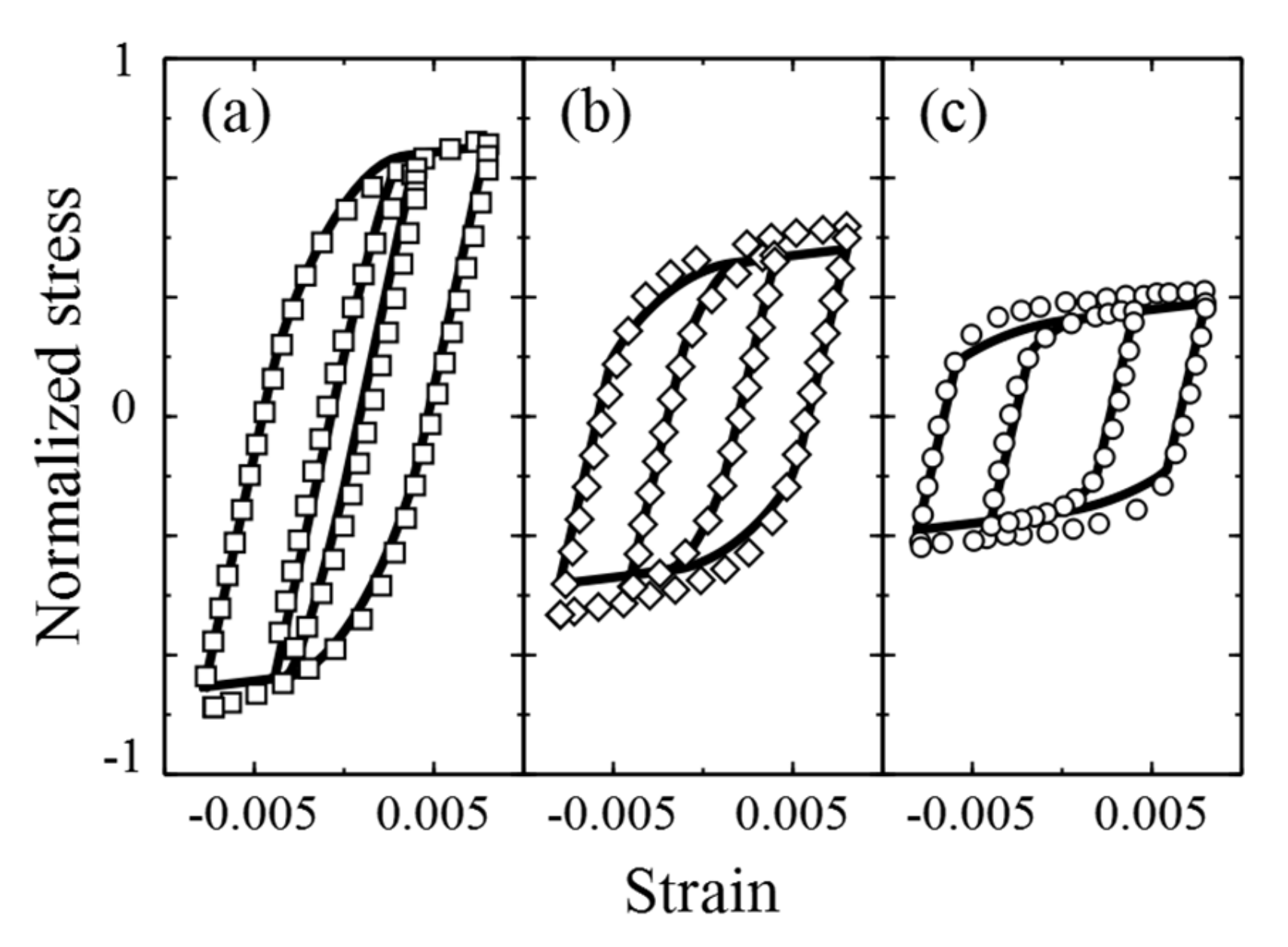
Figure 10 shows the hysteresis strain-stress loops assumed in the design procedure and estimated combining hardness model and cyclic stress strain data for established and proposed models. The current design process yields a dissipated plastic energy, here qualitatively represented as the area of the hysteresis loop and used as cyclic damage indicator as proposed by Constantinescu et al. [
3], about twice higher which results in a lifetime smaller within a factor of 5. This clearly shows the gain in lifetime prediction that can be achieved using a more realistic estimate of over-aging under service conditions as shown in
Table 1.
Once this observation has been made, the bases exist for applying this metallurgical model to loads of variable amplitudes that are much more realistic in terms of actual use. By defining the most statistically representative loading sequences and estimating the associated hardness changes, the estimated lifetime gains could be substantial and allow a more efficient optimization of the cylinder heads.
5. Fatigue Criteria Evolutions
Fatigue criteria are then the last item in design protocols that can be adapted and improved by considering more realistic loading sequences and variable amplitudes. Fatigue data are most of the time obtained on over-aged materials to ensure stable mechanical behavior. However, progressive aging coupled with variable amplitude loading may lead, in the future, to an evolution of fatigue tests protocols and analyses to propose proper fatigue damage estimation throughout robust fatigue criterion. Therefore, in the following we will focus on a proposition on the formalism of models without specifically addressing the theme of thermal aging.
Until recently, and as previously mentioned, one of the main hypotheses commonly used in the automotive industry in TMF design was the decoupling between behavior and damage. Viscoplastic shakedown at each point of the structure is thus assumed after a few loading cycles and it is the “stabilized” cycle that then serves as a reference to characterize the cyclic damage. Constantinescu and co-workers [
3] made the choice, based on previous work [
9,
29], to propose a fatigue criterion relying on the energy density dissipated per stabilized cycle. This choice often leads to quite correct estimation of fatigue lifetime if damage is governed by micro-cracks behavior at the microstructure scale [
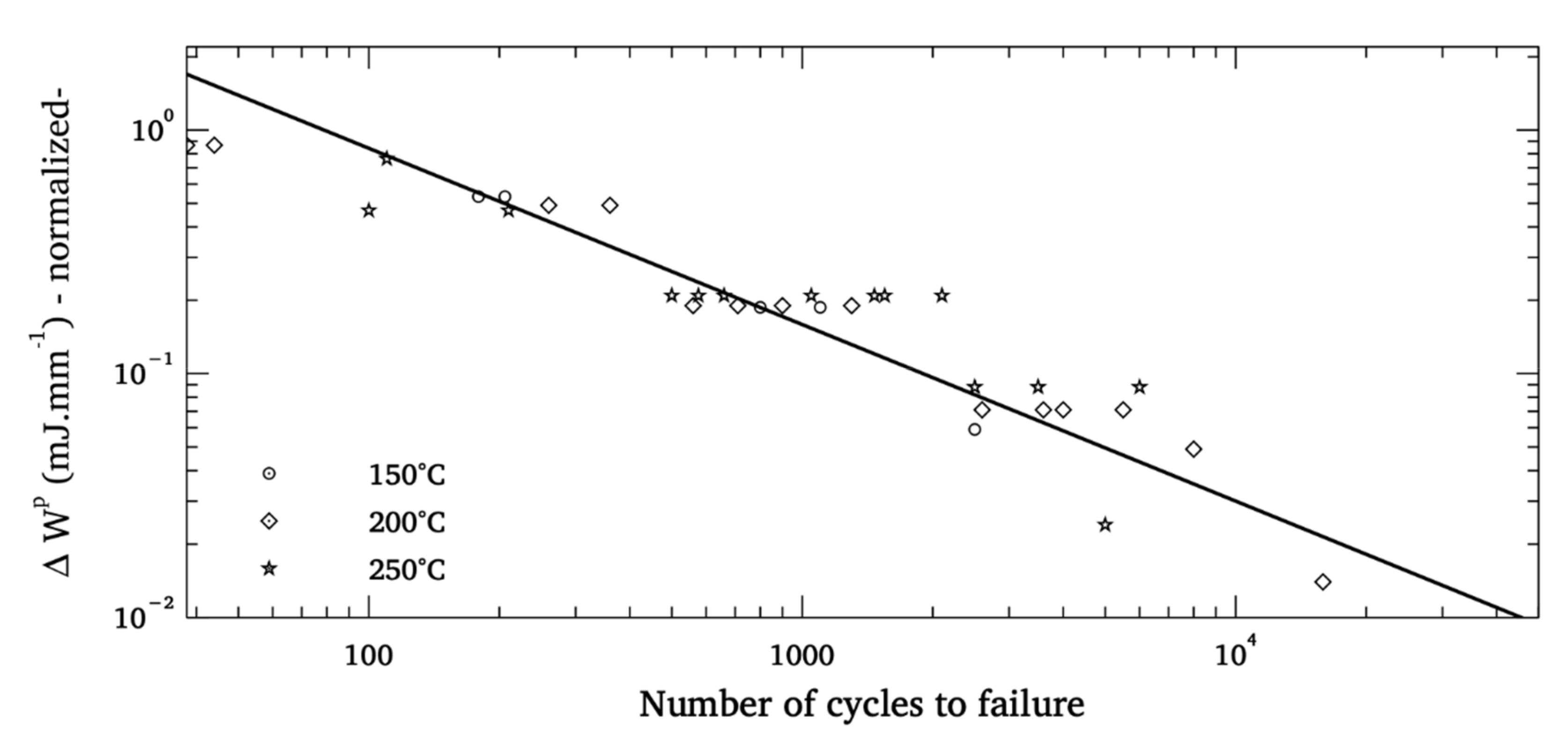
30]. Despite the recognized ability of this type of criterion to provide a good estimate of fatigue life under a given cyclic load at constant amplitude,
Figure 11 reveals for the AlSi7Cu3.5Mg0.1 aluminum alloy a significant dispersion on the correlation between the experimental life and that estimated by the criterion with an average deviation of 41%.
Fatigue resistance is a naturally dispersed property for metallic materials and the analysis of the previous
Figure 11 obviously does not make it possible to decide on the origin of the observed dispersion ( inadequate choice of the criterion mathematical form or damage variable, influence of the material heterogeneities, etc.) and it is maybe simply too ambitious to want to combine under the same formalism and with only two adjustment parameters tests carried out over wide ranges of temperatures and strain amplitude. Indeed, it seems very difficult to characterize the robustness of such criteria without a more detailed analysis of damage mechanisms at the microstructure scale and by mixing experimental and numerical approaches to better understand the physical origin of dispersion. It is also crucial to note that the formalism commonly used and recalled above is not only unable to describe dispersion -and therefore unsuitable for probabilistic design approaches- but also unable to efficiently consider variable amplitude loading. It then appears necessary to build a criterion formalism explicitly incorporating microstructural defect statistics suspected of being responsible for the initiation and micro-propagation mechanisms for foundry metal fatigue: such formalism can easily be integrated into a probabilistic framework but can above all allow a progressive evolution of the damage linked to loads of variable amplitude. Foundry alloys indeed systematically display microstructural heterogeneities which are the consequence of interactions between alloy elements during casting and cooling phases. Aluminum alloys alloyed with silicon, magnesium and copper thus contain many intermetallic compounds [
31,
32] with size and shape that vary according to the cooling rate of the alloy [
33,
34].
The complexity of the castings as well as the parameters of the processes controlling the cooling rates can also generate shrinkage or pores [
35]. These different elements are randomly distributed in the material with particular statistical distributions of size and shape. The study of their role in fatigue damage has often been studied in the high cycle fatigue regime [
36,
37,
38,
39,
40,
41] and it seems relevant to evaluate their role in the case of TMF which is generally synonymous with generalized plasticity. Shadan Tabibian and co-worker’s work on aluminum alloys obtained by lost foam casting has recently opened up reflection on the role of defects in TMF damage mechanisms and introduced a formalism to take into account of the defect population statistics in the basic evaluation of the fatigue lifetime variability [
42]. The main idea developed here is therefore to consider some populations in the material as initial defects, seen as notches from which fatigue damage would develop on a microstructural scale before causing ruin on an engineer’s scale as proposed by Charkaluk. A full 3D characterization of the microstructure through X-ray tomography [
43] can then be performed in order to measure the size and shape distribution of pores in a Representative Elementary Volume as seen on
Figure 12.
A quantitative description of the pore population can be obtained through the measurement of their Feret diameter and sphericity, which could reveal the presence of gassing porosities for lost foam casting processes which are nearly not observed in standard die casting processes. The largest and sharpest pores have to be accurately observed as they play an important part in the fatigue process by acting as crack initiation zone. The pores size distributions could then be introduced in the computational approach used to design engine parts against TMF. Under a basic assumption of growth equation of pores from an initial size
to a final size
at
characterizing a macroscopic crack initiation (a 2 mm-long crack is usually considered here), a fatigue criterion can be developed under a probabilistic form as proposed by [
42] but with an improved formalism regarding the micro-propagation model. Different variable can here be taken as the driving forces for micro-crack-propagation, as proposed by [
30,
44,
45,
46,
47]. The proposition can be summed up in the following improved form of the fatigue criterion:
where
and
denotes respectively inelastic and elastic dissipated energy densities per stabilized cycle, and
, and
are material constants.
is a random variable that consists in the observed statistical distribution of pore size in the tested volume and finally to the risk of finding a pore of a given size. The observed then analyzed volumes are however often of different sizes from those of fatigue specimens. Statistical treatments then correct the observed distribution in order to and to become independent of the size of the observed areas [
48]. Corrected pore size distribution can be directly integrated in the semi-probabilistic fatigue criterion as probability of occurrence while material parameters are identified from the standard macroscopic low-cycle fatigue and TMF experiments. This criterion better reflects the effects of mean stresses, which are very important for uniaxial fatigue tests as well as for crack propagation tests, especially under conditions where plasticity is widespread. The particular mathematical form of Equation (2) forbids a conventional lifetime analysis. The number of cycles to failure is therefore linked to an energy density couple and a defect-size distribution. When crack propagation is investigated on laboratory specimens, a direct access to the parameters is possible. In other cases, the simple numerical identification of the parameters of such a model is quite complex because no analytical description is possible. While experimental data are missing, treatment is then carried out for classes of pore size. For a given pore size and for a given set of parameters
, the estimated lifetime is easily calculated. A histogram and a complete distribution of the number of cycles to failure are then obtained. For a given experimental couple
, the number of cycles to failure with the highest probability is then finally compared to the experimental lifetime. A least-squares optimization is then performed to obtain the most relevant parameter set.
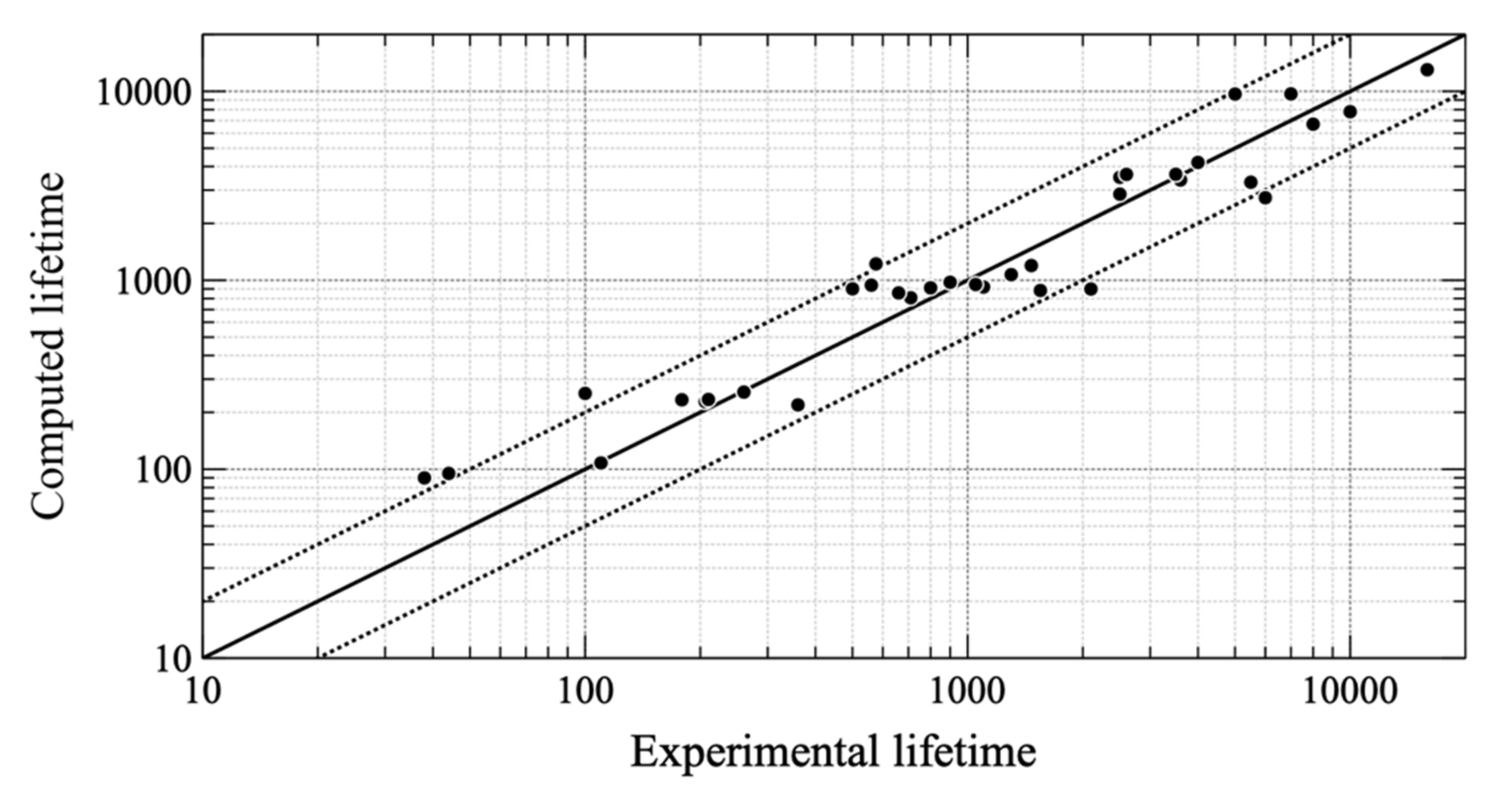
Lifetime prediction results can then be compared with laboratory specimens. Following this simple principle, good matching is obtained between estimated and experimental lifetimes as seen on
Figure 13. A micro-propagation crack growth law, closer to physics, therefore makes it possible to obtain a more realistic estimate of the fatigue lifetime scattering and certainly more in line with the experiment [
42]. A formalism that introduces both micro-propagation cracks growth law with driving forces composed from macroscopic energies combined with statistics of microstructural features taken as initial defects yields promising results. The introduction of the role of microstructure in damage evolution seems unavoidable for foundry materials, but the proposed protocol is most of time faced with the difficulty of obtaining reliable experimental results. It therefore seems mandatory, in view of these initial results, to add crack propagation tests on SEN-type specimens [
30,
47,
48,
49,
50] to have access to reliable laws and to carry out test campaigns systematically proposing repetitions of one or more tests to obtain first estimates, even partial, of the effective fatigue lifetime scattering of the couple material/process to be evaluated. In the case of materials sensitive to thermal aging, the choice of relevant tests to be carried out is all the more crucial, as is the need to have a large database. The development of strategies to maximize the information obtained on fatigue resistance by minimizing the number of tests to be performed remains an important challenge for the coming years.
The use of micro-propagation laws also opens the way to a new formalism for criteria and introduces a notion that until now has often been set aside from design protocols for TMF: non-linear accumulation of damage. For the sake of simplicity, the accumulation of damage is generally described by Miner’s rule [
51] without considering the role of the loading history. This hypothesis, which is often conservative, is also perfectly adapted to the standard formalism of the criteria. A propagation law, because it incorporates an initial crack size and varies the propagation rate according to the crack size, is more suitable for estimating the historical effects of loading and also variations related to thermal aging. However, it has the major drawback, for a design process that has to be the fastest as possible, of having to compute more loading cycles. The analyses of a realistic sequence of loading cycles as seen on
Figure 5 however undoubtedly underlines the real need to change the paradigm from a hypothesis of almost systematic structural shakedown under a single type of loading cycle, assumed representative and involving a linear accumulation of damage, to longer evolutions based on statistically representative sequences and non-linear cumulative damage. It will then be a question of estimating as well as possible the sequences of cycles to be analyzed in a compromise to be found between the computation times and the confidence given to the estimation of the mechanical resistance
6. From Experimental Specimens to Real Structures: A Validation Strategy
The validation strategy of an industrial structure submitted to thermal–mechanical loads is usually basic. Constitutive models and fatigue criterion are validated on laboratory specimen with tests close to the ones that are used to identify their parameters [
2,
48]. These tests, due to their ease of implementation, deeply simplify real structural loading conditions. Thermal gradients, which are most often responsible for TMF damage, are suppressed in order to provide a stress/strain direct analysis. When these gradients become very severe and when variable amplitude loadings existence is well-established, it is mandatory to include them in an objective comparison of material/process solutions. Final tests on real structure are also performed but due, to their difficult analyses, are unsuitable to really optimize models.
In these cases, it becomes necessary to build specimens closer to the structure to be designed and therefore often more complex in terms of geometry and loading conditions. In the automotive world, a first solution has been proposed by Constantinescu and his co-authors [
3]: a clamped heated specimen that reproduces loading conditions observed on a cylinder head but with gradients often too severe. The last part of the validation strategy against TMF for cylinder heads uses an experimental analysis of a “single-cylinder” specimen as seen on
Figure 14 which provides loading conditions as close as possible to the structure ones while respecting both the microstructure and the surface roughness in the critical zone. A blowtorch is used to heat the fire deck and is first designed to reproduce the thermal loading generated by the engine start and stop. The single-cylinder stands in front of the blowtorch during the heating phase then draw aside from the blowtorch to reproduce a natural cooling (like a real cylinder head, the specimen is cooled by a dedicated water circuit maintained at 20 °C). During cooling, Damage evolution on the surface is monitored thank to a camera that detects cracks macroscopic initiation. To correctly reproduce real cylinder heads rigidity, the single-cylinder specimen includes seats and valves guides both shrink-fitted on the structure. A support is added to represent the real interface with cylinder block. In order to evaluate the representativeness of the thermal loadings, welded thermocouples carry out a real-time thermal loading control.
By controlling the blowtorch power, it could be possible to modulate the loading amplitude but so far unfortunately impossible to apply complex sequences of variable loadings. However, the set-up evaluates the evolution of the macroscopic damage on the structure, and then, thanks to a comprehensive finite element model, to validate the design strategy, including constitutive models and damage approaches. The numerical part of the validation strategy is based on the sequence described in
Figure 1. All the improvements that have been previously proposed can be easily integrated into this protocol.
The first step of the calculation is a transient thermal analysis performed by Abaqus as seen on
Figure 15, corresponding to the heating and cooling phases of the test on the single-cylinder. The calculation is adapted to fits with the experimental temperature measurements. As previously stressed, an accurate temperature field during a cycle is mandatory to analyze thermal aging and then to obtain the correct mechanicals stresses. As presented in
Section 4, the maximum temperature field during heating determines the aging condition of the structure. Then, material properties are updated for each integration point. The mechanical calculation considers the evolution of the temperature field during the loading cycle as boundary conditions (weak coupling) to obtain the structure local mechanical evolution: a complete shakedown is usually observed after 3 to 10 loading cycles at constant temperature amplitude.
Finally, a TMF criterion is applied to estimate the lifetime of the component and detect the critical zones as seen on
Figure 16. These results highlight that the value of the dissipated energy density is of course dependent on the mesh size. It is therefore mandatory to adjust the probability of finding pores taken as initiation defects in an element volume
Vc to obtain reliable results when using our proposed formalism for fatigue criteria. More precisely, one must compute the probability of the presence of at least one pore of a given size in the critical volume
Vc (as explained in [
49]) and estimate the associated lifetime using Equation (2). This method, applied on AlSi7Cu3.5Mg0.1 single cylinder specimens, provides encouraging results as highlighted on
Figure 17. A good estimation of the lifetime mean value is obtained and a first approximation of the standard deviation could also be underlined.
Finally, it is crucial to underline that the use of elasto-viscoplastic constitutive models combining specific equations such as those presented above, induces a major difficulty for finite element analyses. Such complex models are usually not integrated in industrial solvers as Abaqus which however offer to code a user model. This step requires the necessary complex writing of a numerical integration scheme, widely documented in the literature [
52] and already applied for physically-based models in the automotive industry [
19,
53]. The integration procedures are based on a fully implicit integration scheme associated with a radial return, which has been proved unconditionally stable and faster for temperature dependent yield limit and viscous flow. Different schemes could then be used with strong differences in complexity, time computation and precision [
54]. If in the past, it was mandatory to write and then code the entire integration scheme in this case, generally including the calculation and then the inversion of a Jacobian matrix, tools are now available to facilitate this step and thus facilitate access to the use of more advanced constitutive models such as MFRONT [
55] or Zset [
56]. This simplification of numerical integration is a major step in facilitating the use of more reliable models that are essential for representing complex loads with variable amplitudes.
7. Conclusions
Since the late 1990s, the automotive industry has developed design protocols against thermomechanical fatigue for engine parts. These protocols were based on design and validation loads, generally identical, and deliberately chosen as severe to ensure the necessary safety margins and avoid any failure in use. These protocols make it difficult to optimize the designed structures and tend to provide a high level of conservatism.
The improvement of knowledge on foundry materials, coupled with the possibility of making measurements more and more easily and the increase in the capacity of computing means, opens the way to probabilistic design protocols. The latter make it possible to evaluate a risk of failure but above all to introduce, in the protocols, the necessarily random nature of car loads. This point is thus the key to new design protocols and above all the gateway to many model improvements, which will allow a real optimization of the designed structures and therefore a net decrease in conservatism.
Figure 18 summarize the proposed improvements made to well-established TMF design protocol.
At the origin of the reconsideration of the usual protocols, we underlined the introduction of aluminum alloys richer in copper and therefore better adapted to the increasing temperatures of use. These materials have a different sensitivity to thermal aging than those observed on previous alloys with a dependence of the over-aged state on the aging temperature. This observation directly challenges the computation strategies based on the definition of two different stable metallurgical zones from the beginning of the calculation. In addition, it also fails to use a very severe design cycle that will then induce a high and unacceptable level of conservatism to achieve true optimization for the cylinder head. The precise analysis of automotive loads also highlights their high variability with thermal and mechanical amplitudes that are often lower than those used in conventional design protocols. We therefore proposed to establish loading sequences statistically representative of actual use based on complete measurements of the various usage situations and signal processing appropriate for thermomechanical fatigue.
Considering the reality of the thermal and mechanical loadings and their variability necessary modifies the way of designing structures against thermomechanical fatigue. The use of simplifying assumptions to consider the behavior of aluminum alloys and their over-aging is now incompatible with the need to produce reliable and robust design protocols. In fact, the in-depth analysis of loading conditions and the development of models that are as close to physical reality as possible for both behavior and damage are nowadays indispensable ways of ensuring reliable fatigue design.
We therefore proposed an original solution to model the behavior of aluminum alloys using a metallurgical model linking microhardness to the thermal aging condition. By introducing a dislocation density as an internal variable in the constitutive model and using an adapted experimental database, we propose a reliable constitutive model that successfully reproduces the alloy behavior for many aging conditions without increasing the number of parameters to be identified and by introducing physical constants from the literature, the evolution of which with temperature is well known. This model is perfectly adapted to loads of variable amplitudes while the associated numerical strategy still needs to be refined and in particular the strength of the coupling to be introduced to obtain the best compromise between the accuracy of the results and the duration of the calculation. In a complementary way and once again to follow behaviors that evolve over different amplitude cycles, we propose to introduce fatigue criteria once again related to the physics of damage. Based on the probability of finding pores of different sizes in a given volume, we introduce a probabilistic criterion based on a micro-propagation model. This proposal is perfectly in line with the variable nature of the load and allows the thermomechanical problem to be dealt with by means of an accumulation of non-linear damage.
Examining these results with the search of an always better knowledge of thermal loads and the possibility of implementing more complex tests also pave the way for "structure" type tests, which are proving to be essential in future design strategies. At the heart of the digital strategy, these will first of all validate and fault models and then necessarily make them evolve. These models will then make it possible, in a virtuous loop, to improve experimental protocols in order to produce more reliable and instructive tests. By concentrating all the richness of the real loads in a single test, the way also opens up to the systematic study of experiential lifetime scattering, essential for probabilistic design. These tests can also lead to systematic optimization of cylinder heads, in line with the real usage of these structures.
The search for intermediate specimens between the industrial structure subjected to often complex use constraints and the simple volume element of the fatigue specimen will therefore undoubtedly constitute a field of research in the coming years, accelerated by the emergence of experimental techniques for fatigue such as image correlation or infrared thermography. Today, it is a necessary step to improve constitutive models and fatigue criteria while accessing to a fully integrated consideration of the role of microstructure in thermo-mechanical fatigue damage mechanisms.
Finally, it is necessary to stress that all these developments will have to be accompanied by appropriate numerical strategies. If computing powers tend to increase regularly, it seems illusory to think that numerical models will see their degree of freedom increase forever. Digital development will have to be more agile and adapted to design protocols evolutions: considering more variability sources and introducing more physics in models must be accompanied with reasoned calculations with limited size and that are really useful to design processes.

 ,
, 


