Abstract
Cold forging is a metal forming that which uses localized compressive force at room temperature. During the cold forging process, the tool is subjected to extremely high loads and abrasive wear. Lubrication plays an important role in cold forging to improve product quality and tool life by preventing direct metallic contact. Surface roughness and residual stress also greatly affects the service life of a tool. In this study, variations in surface roughness, residual stress, and specimen deformation with the number of cold forging cycles were investigated under different forging conditions. Specimens that were made of heat-treated SKH51 (59–61 HRC), a high-speed tool steel with a polished working surface, were used. The specimens were subjected to an upsetting process. Compressive residual stress, surface roughness, and specimen deformation showed a positive relationship with the number of forging cycles up to a certain limit and became almost constant in most of the forging conditions. A larger change in residual stress and surface roughness was observed at the center of the specimens in all the forging conditions. The effect of the magnitude of the forging load on the above discussed parameters is large when compared to the effect of the lubrication conditions.
1. Introduction
Forging is one of the well-known manufacturing methods that have been used to produce high quality and tough products under temperature-controlled conditions by shaping metal while using localized compressive forces. Based on the temperature at which the forging process is performed, it is divided into three categories: hot, warm, and cold. Cold forging, which is performed at room temperature, has gained importance in the field of steel-based products over the last sixty years [1]. There are many advantages of cold forging, such as excellent mechanical properties of the forged part, minimum material wastage, and the ability to forge a net shape or near-net shape product. However, the cold forging tools are subjected to a combination of abrasive wear and very high mechanical loads, which generates a surface pressure of up to 3000 MPa that is caused by high flow stress of the billet material at room temperature [2,3]. Overstressing of the tool, abrasive wear, galling or adhesive wear, and fatigue failure are common failure modes of cold forging tools [4]. The cyclic loading of tools causes’ fatigue, and a combination of high contact stress and cumulating sliding strength causes the wear [5].
The tribological system plays an important part in designing robust and efficient cold forging operations [6]. Efficient lubricants assist in improving the product quality and tool life by reducing the forging load and wear by preventing direct metallic contact between the tool and the workpiece [7]. The lubricant used in cold forging is subjected to very severe conditions due to the very high surface expansion and interface temperature [8]. If the lubricant used is unable to withstand the above mentioned conditions, it will lead to product defects or tool failure. However, interest in dry forging (without lubrication) is highly increasing to reduce the financial costs, environmental impact, and possible health burden [9]. The effect of lubrication on tool life is not only studied in forging, but also in machining processes. Martinez Krahmer et al. [10] investigated the tool wear during dry and wet turning of free-cutting steels by using uncoated hard metal inserts at three cutting speeds and found that tool wear exhibits slightly better performance in the dry machining condition for higher cutting speeds. Herrmann et al. [11] studied the effect of the structuring of tools used for the cold forming process’ rotary swaging, under conditions either with or without lubrication and with different feeding velocities. They found that the axial reduction force can be effectively reduced by the shaping of the structure and the use of lubrication. Hafis et al. [12] evaluated the effects of lubricant quantity on forming loads and surface finish under dry and lubricated conditions among die-workpiece sliding surfaces in the cold work drawing process. They found that poor lubrication increases the forming load, reduces the shape precision, and increases the surface roughness of the product.
Surface roughness plays a significant role in forging in terms of tool service life and forged product quality. Higher surface roughness in the forging tool will increase the friction between the tool and the workpiece. The negative impacts of high friction are, among others, energy dissipative effects, increased energy consumption, and a reduced tool life due to increased wear and the forming forces [13]. In general, fatigue life decreases as the surface roughness increases, particularly in the high cycle fatigue (HCF) region, and it has less effect on the low cycle fatigue (LCF) region [14]. The effect of the roughness on the wear of cold forming tools was investigated while using punch made of AISI M2 hardened steel by Souza et al. [15]. The study showed that different tool regions have different types of wear and that the punches with high surface roughness were prematurely broken. Furthermore, they stated that these faults in punches were related to the initial topography of the tools. Syahrullail et al. [16] studied the effect of tool surface roughness on a cold extrusion process. They concluded that higher surface roughness increases the extrusion load and affects the material flow. Martinez Krahmer et al. [17] studied on the effect of the manufacturing methods on the surface state and tensile test performance of low-carbon steel specimens. Their results showed that some changes on surface state appeared to depend on manufacturing method and influence the tensile strength. Therefore, the selection of manufacturing method is very important, because the initial surface condition generated by the manufacturing process will greatly affect the final results of the experiment or the tool life.
Residual stress is defined as the stresses that exist within a body in the absence of external loading or thermal gradients. Residual stresses in any mechanical structure can occur through a variety of mechanisms, including plastic deformations, temperature gradients during thermal cycles, or structural changes with phase transformation. The residual stresses that were generated by tool production and external stresses induced by the forming process have a major effect on tool life in cold forging [18]. Czan et al. [19] analyzed the residual stress in subsurface layers after the precision hard machining of forging tools by the X-ray diffraction method, and the residual stress had a compressive character. Furthermore, Merklein et al. [1] studied the influence of the machining process on residual stresses in the surface of cemented carbides, which is a commonly used material for die inserts in the forging tools. The results showed that the electrical discharge machining (EDM) process induces tensile stresses in the top layer, while grinding is accompanied by compressive stresses. Additionally, they found that the surface compressive stresses associated with grinding followed by polishing are higher than those that are associated with EDM, followed by polishing.
Studies have been carried out on compensate forging tool deformation during operation in tool design to achieve better tool life and product quality. Del Pozo et al. [20] studied the die deflection during the pressing process. They proposed a methodology for the accurate manufacturing of drawing dies based on the prediction of press/die deformation during operation. They stated that with their methodology the manual adjustment time and hand polishing time can be reduced by 30%. Rosochowski [21] proposed a design procedure for cold forming tools by taking into account the component springback and die deflection during forming, mainly for the net shape forming process.
Any improvement in the service life of tools reduces the tooling costs, and it assists in increasing labor productivity by decreasing the need for either the tools’ re-grinding or their replacement [22]. Thus, there are many studies that are carried out on various methods to improve the tool life of forging tools by altering the residual stress and surface properties. Shot peening is a mechanical surface treatment method that is used to improve the service life of forging tools by increasing the surface compressive residual stress. Chang et al. [23] studied the effect of shot peening on wear properties and the die life while using shot peening-treated AISI H13 steel and they found that the optimal shot peening treatment increased the die life for cold forging by over three times and hot forging molds by two times. Harada et al. [24] researched the micro-shot peening of high-speed tool steel and claimed a significant increase in fatigue performance. Popp and Engel [25] studied the influence on the tool life of the cold forging tools due to surface topography alternation by micro-texturing. Their results proved that the tool life can be significantly increased, in some cases over 300%. In the above studies, the researchers had altered the surface properties prior to the experiment and studied the effect. However, there was no comprehensive study that was carried out on the variation of residual stress and the surface conditions of the forging tool during service. The understanding of the in-service variation of different parameters that affect tool life will lead to new scopes in tool life improvement methods, such as partial surface treatment, tool design with predicted deformation, advancement in the tribological system, etc. Therefore, it is of the utmost importance to research and understand the in-service variation of parameters that affect tool life.
The present study has the scope to investigate the variations in surface roughness, residual stress, and the deformation of a tool with the number of cold forging cycles under different forging conditions. The experimental method was designed to execute the research in similar conditions to an actual cold forging process. A cold forging upsetting process was carried out with specimens that were made of heat-treated SKH51 material as a punch under conditions with lubrication and without lubrication, with two different forging loads. The influences of lubrication and forging load on surface roughness, residual stress, and specimen deformation were evaluated and the effect of these parameters on tool life was discussed.
2. Materials and Methods
2.1. Materials, Specimen Preparation, and Lubricant
A molybdenum-based high-speed tool steel JIS SKH51 (AISI M2; DIN 1.3343) was used. Table 1 shows the chemical composition of the material. SKH51 is commonly used in cold forging tool manufacturing due to its specific mechanical properties, such as high abrasion resistance and toughness characteristics. SKH51 is a tool steel that can achieve a high hardness of over 60 HRC and a high compressive strength of over 3000 MPa [3].

Table 1.
Chemical composition of SKH51 (wt.%).
The specimen was made out of a round bar of steel in such a way that the loading direction is similar to the grain flow direction of the steel. Roughly machined specimens were preheated at 550 °C and 850 °C before being austenitized at 1120 °C. This was followed by quenching and tempering three times at 560 °C, to achieve a hardness of 59–61 HRC. The heat-treated specimens were NC lathe machined to get the outer shape. The top and bottom surfaces of the specimens were ground and the working surface was polished while using diamond paste to get a mirror-like surface finish. Figure 1 shows the specimen image and initial dimensions before the test. The yellow transparent metal working fluid “Sunform 350”, as manufactured by Nihon Grease Co., Ltd, Tokyo, Japan, was used as the lubricant for the experiment. Table 2 shows the properties of the lubricant.
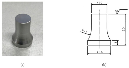
Figure 1.
Geometry of the specimen used for the experiment: (a) image; (b) dimension (unit: mm).
Table 2.
Properties of the lubricant “Sunform 350”.
2.2. Experimental Setup
Figure 2a shows the Shimadzu UH-500KNX universal testing machine (Shimadzu Corporation, Kyoto, Japan). The maximum loads were 150 kN and 180 kN, which corresponded to contact pressures of 1910 MPa and 2290 MPa, respectively. Figure 2b shows the zoomed experimental setup. The specimen was glued to the upper head of the universal tester. A low carbon steel SPCC (JIS G3141) sheet with 1.6 mm thickness placed on a spacer with high hardness (65 HRC) was used as the counter face. The zero limit of the stroke was set at 1mm below the point at which the 1 kN load was obtained. The base of the universal tester was moved upward at a speed of 25 mm/min. until the load became the set maximum load, and it stayed there for 1 sec. Thereafter, the base was moved downward until the stroke reached 1 mm from the starting position. The forging process was performed with lubrication and without lubrication as the conditions. The lubrication was periodically applied on the area near the specimen working surface to make sure that the forging operation was done in a lubrication bath for the ‘with lubrication’ condition throughout the experiment. The experiment was repeated for 14000 cycles for each forging condition, with an interval of 1000 cycles to take measurements. “WL” and “WOL” are used to denote the ‘with lubrication’ condition and the ‘without lubrication’ condition, respectively.
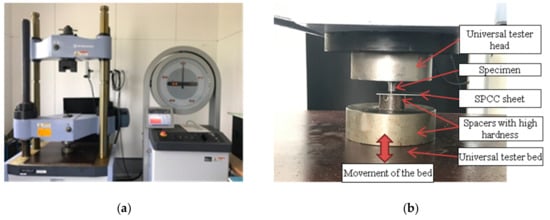
Figure 2.
Testing machine and experimental setup: (a) universal testing machine (UH-500KNX); and, (b) experimental setup.
2.3. Measurements
Figure 3 shows the schematic of the dimension change of the specimen due to loading. The initial outer diameter (near the working surface), D, increased by ΔD due to the applied load, while specimen height, H, reduced by ΔH. Furthermore, a deformation at the center with a downward displacement, Z, was observed after loading.
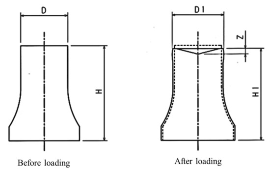
Figure 3.
Schematic of the dimension change of the specimen due to loading.
Dimensions (D and H), residual stress (σ), surface roughness (Ra), and downward displacement (Z) were initially measured and after every 1000 cycles of forging. The diameter (D) and height (H) of the specimens were measured while using a digimatic micrometer (Mitutoyo Corporation, Kawasaki, Japan) and height gage with a resolution of 1 μm, respectively. The surface roughness (Ra) and residual stress (σ) of the specimen were measured by the surface roughness tester, Surfcom-130A (Tokyo Seimitsu Co., Ltd, Hachiōji, Japan) and the portable X-ray residual stress analyzer, Pulstec μ-X360 (Pulstec Industrial Co., Ltd, Japan), respectively. Figure 4a,b, shows the surface roughness measuring direction (measuring length 4 mm) and the residual stress measuring areas, respectively. A contour measuring instrument, Surfcom-1600GH (Tokyo Seimitsu Co., Ltd, Japan) was used to measure the downward displacement (Z) on the working surface and it was measured through the center from edge to edge, as shown in Figure 4c. The images of specimen surfaces were taken while using an optical microscope, BX-41M (Olympus Corporation, Tokyo, Japan).
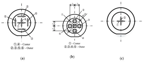
Figure 4.
Measuring details: (a) surface roughness measuring directions; (b) residual stress measuring areas; and, (c) surface deformation measuring directions (From edge to edge through the center).
3. Results and Discussions
3.1. Working Surface Conditions and Surface Roughness
Figure 5 shows the surface images of the initial, intermediate, and final working surfaces for all forging conditions. The images show a gradual increase in scratch marks on the surface with the number of forging cycles for all of the forging conditions. The scratch marks were due to the wear of the working surface that was caused by material movement. The shininess of the specimen surfaces on which lubricant was used deteriorated as the number of forging cycles increased. Furthermore, a brownish color substance accumulated on the working surface of specimens that were subjected to forging without lubricant. These were identified as ferrous oxide using an X-ray analytical microscope. Krajewski et al. [26] stated that iron exposed to air or oxygen containing atmosphere always tends to be instantly oxidized, even at room temperature. Moreover, the study of Ghasemi et al. [27] showed that significant quantities of oxides quickly formed on a steel ball during fretting, even with surface temperatures as low as 25–30 °C. It is known that the surface temperature increase is high due to direct metallic contact, when compared to the presence of lubrication between the surfaces. The oxide layer was clearly observed on the working surface of the specimens without lubricant since the temperature increase stimulated the oxidation process. On the other hand, the lubrication blocks the contact between the surface and the atmosphere, preventing the oxidation on the working surface of specimens that were forged with lubrication.
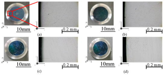
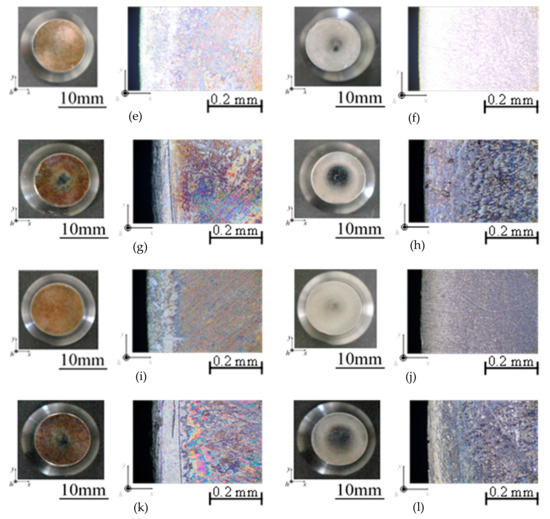
Figure 5.
Working surface conditions. (Left—full image, Right—magnified image): (a) 150 kN (WOL)—Initial; (b) 150 kN (WL)—Initial; (c) 180 kN (WOL)—Initial; (d) 180 kN (WL)—Initial; (e) 150 kN (WOL)—7000 cycles; (f) 150 kN (WL)—7000 cycles; (g) 180 kN (WOL)—7000 cycles; (h) 180 kN (WL)—7000 cycles; (i) 1150 kN (WOL)—14,000 cycles; (j) 150 kN (WL)—14,000 cycles; (k) 180 kN (WOL)—14,000 cycles; and, (l) 180 kN (WL)—14,000 cycles. (WL—With Lubrication, WOL—Without Lubrication).
Figure 6 shows the average arithmetic surface roughness, Ra at the center and the average value of outer areas by the number of forging cycles, N, for the 150 kN load condition. The surface roughness of the specimen that was forged with lubrication showed a slightly lesser surface roughness increase when compared to the ‘without lubrication’ condition. Regardless of the lubrication condition, the surface roughness at the center rapidly increased at the beginning. Thereafter, it gradually increased until reaching a constant value. On the other hand, the surface roughness of the outer areas gradually increased at the beginning and became constant. A comparatively large difference in surface roughness change is observed between two lubrication conditions at the beginning, and the difference narrowed as the number of cycles increased. There was a large surface roughness difference between the working surface of the specimen (about Ra 0.03) and the counter face (about Ra 0.60) at the beginning of the experiment. Therefore, the surface roughness change is high for the without lubrication condition at the initial stage, due to the direct contact of the fine surface with a rough surface. On the other hand, direct contact was congested with the use of lubricant. Therefore, a low surface roughness increase was observed at the beginning. As the forging process progressed, the difference between the surface roughness of the specimen working surface and counter face decreased. Thus, the surface roughness became almost the same for both lubrication conditions after 14,000 cycles.
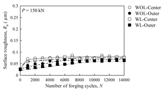
Figure 6.
Average arithmetic surface roughness at the center and the average of outer areas by the number of forging cycles, for the 150 kN forging load. (WL—With Lubrication, WOL—Without Lubrication).
Figure 7 shows the average arithmetic surface roughness, Ra at the center and the average value of outer areas by the number of forging cycles, N, for the 180 kN load condition. The surface roughness for the 180 kN load condition is very high and the difference between the center and outer areas is significant when comparing with the results of the 150 kN load condition. Similar to the 150 kN load condition, the surface roughness of the specimen that was forged with lubrication showed a slightly lesser surface roughness increase as compared to the ‘without lubrication’ condition. This slight difference may have resulted from the oxidation occurring on the surface under the ‘without lubrication’ condition.
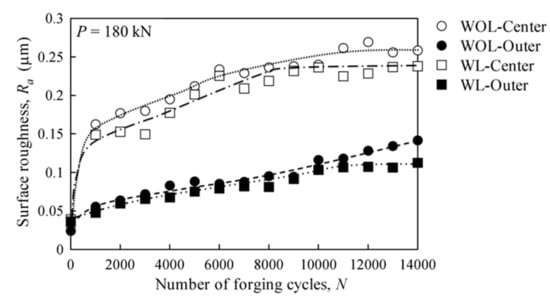
Figure 7.
Average arithmetic surface roughness at the center and the average of outer areas by the number of forging cycles, for the 180 kN forging load. (WL—With Lubrication, WOL—Without Lubrication).
There was a relative movement between the working surface of the specimen and the counter face material due to the deformation. The contact areas and forces are responsible for the generated friction, wear and change in surface roughness during the relative motion of the two bodies [28]. The wear on the working surface mainly caused the increase in surface roughness under all the forging conditions. Dry sliding contact between metallic surfaces is often associated with high surface temperatures, which form an oxide layer, resulting in high friction and severe surface damage [29,30]. Lubrication creates a barrier between the contacting surfaces and it eliminates direct contact between them. Therefore, the wear of the working surface is comparatively low in the presence of lubricant, which results in a low surface roughness increase when compared to the dry forging condition.
3.2. Residual Stress
Figure 8 shows the compressive residual stress, at the center and the average of the outer areas by the number of forging cycles, N, for 150 kN load condition. The initial residual stress on the working surface of the specimens was compressive in the radial direction, and it was considered to be generated by machining and polishing performed during specimen preparation. Regardless of the lubrication condition, the residual stress of the center and the outer areas both showed an initial rapid increase, followed by a gradual increase, reaching a constant value thereafter. Furthermore, the ‘without lubrication’ condition showed a slightly higher compressive residual stress than the ‘with lubrication’ condition. Relatively high compressive residual stress was observed at the center when compared to the outer areas for both lubrication conditions.
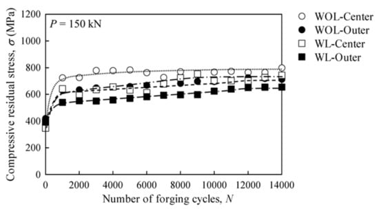
Figure 8.
Compressive residual stress at the center and the average of outer areas by the number of forging cycles, for the 150 kN forging load. (WL—With Lubrication, WOL—Without Lubrication).
Figure 9 shows the compressive residual stress, at the center and the average of outer areas by the number of forging cycles, N, for the 180 kN load condition. The compressive residual stress at the center for both of the lubrication conditions increased at a higher rate and became almost constant at around 7000 cycles. On the other hand, the variation of residual stress in the outer areas did not show a significant increase. At the 150 kN load condition, compressive residual stress increased at both the center and outer areas. However, a large increase in compressive residual stress was found only at the center at the 180 kN load condition.
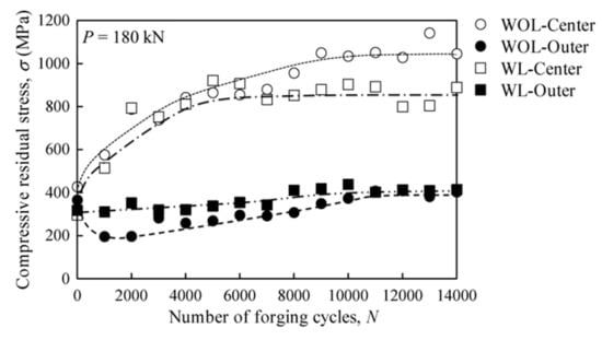
Figure 9.
Compressive residual stress at the center and the average of outer areas by the number of forging cycles, for the 180 kN forging load. (WL—With Lubrication, WOL—Without Lubrication).
Jiang et al. studied the effect of machining process and polishing on residual stress [31]. Their study showed that significant compressive stress was present in ground materials, whereas a tensile stress on EDMed surfaces. Moreover, the compressive stress in the ground materials was strongly enhanced when compared to that of polished materials. The specimen preparation process consists of surface grinding, and polishing. Thus, the initial residual stress on the working surface of the specimens was compressive in the radial direction. Plastic deformation is one of the mechanisms that generate residual stress. Plastic deformation occurs and some residual stresses will remain after unloading when the stress exceeds the elastic limit of the material during loading [32,33]. Compressive residual stresses are generated when the surface is plastically deformed due to a compressive force and they are trying to return to the original position. The larger compressive residual stress that was observed for 180 kN reveals that a larger plastic deformation occurred under this condition.
3.3. Deformation of the Specimens
Figure 10 shows the cross-section images of the specimens after 14,000 forging cycles. Even though the downward displacement at the center of the specimens that were subjected to the 150 kN load was not clearly visible at the current magnification, the displacement of the specimens subjected to 180 kN was clearly observed. According to the pressure distribution equation that Timoshenko and Goodier gave [34], for a circular sectioned punch that was subjected to load under the frictionless condition, the highest pressure/stress appears at the center of the punch. Higher plastic deformation occurs at the center when the stress at the center largely exceeds the elastic limit of the material.
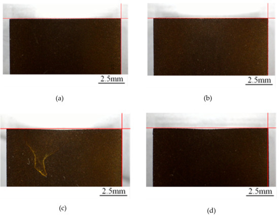
Figure 10.
Cross-section image of the specimen after 14,000 forging cycles: (a) 150—WL; (b) 150—WOL; (c) 180—WL; and, (d) 180—WOL. (150/180—Forging load (kN), WL—With Lubrication, WOL—Without Lubrication).
Figure 11 shows the variation in the downward displacement, Z, by the number of forging cycles, N. A larger displacement was observed under the 180 kN condition. The downward displacement with lubrication had close resemblance to that of ‘without lubrication’, in the case of a forging load of 150 kN. However, in the case of a forging load of 180 kN, the center deformation with lubrication was larger than that of the ‘without lubrication’ condition. The lubrication encouraged the plastic deformation of the specimen. Regardless of lubrication and load conditions, the downward displacement rapidly increases at the beginning, followed by a gradual increase and then a constant value. Work hardening occurs on surfaces that are subjected to cyclic loading, which increases the strength of the material and increases the elastic limit. Thus, the propagation of deformation of the specimen was terminated after a certain number of forging cycles.
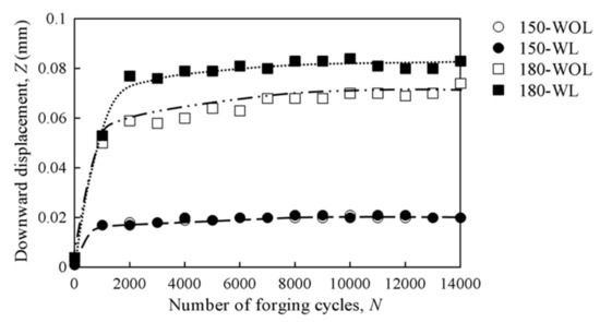
Figure 11.
Variation in the downward displacement by number of forging cycles. (150/180—Forging load (kN), WL—With Lubrication, WOL—Without Lubrication).
Figure 12 shows the variation in specimen average height reduction, ΔH, by the number of forging cycles, N. A large height reduction was observed on the specimen that was subjected to the 180 kN load when compared to specimen subjected to the 150 kN load. Regardless of forging load or lubrication conditions, a large height reduction was initially observed. This was followed by a further decrease with a slower rate, and finally by a constant. Z and ΔH show the same tendency against the number of forging cycles.
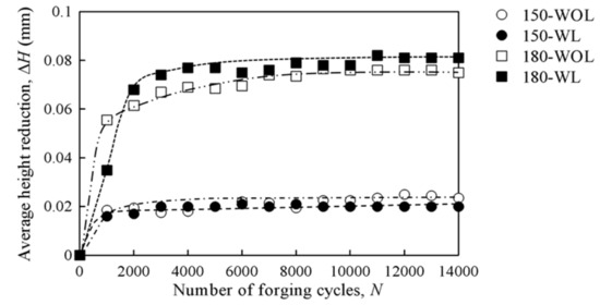
Figure 12.
Variation in the specimen average height reduction by number of forging cycles. (150/180—Forging load (kN), WL—With Lubrication, WOL—Without Lubrication).
Figure 13 shows the change in the variation of the outer diameter (near the working surface), ΔD, by the number of forging cycles, N. A large change in diameter was observed for the 180 kN load condition when compared to the 150 kN load condition. The diameter changes under the ‘with’ and ‘without’ lubrication conditions are almost the same for the 150 kN forging load. Furthermore, when the forging load was 150 kN, the diameter of the specimens gradually increased until 11,000 cycles, followed by no change. In contrast, when the load increased to 180 kN, the diameter of the specimen continued to increase until 14,000 cycles. Furthermore, an effect of lubrication on diameter change was observed under the 180 kN load condition. The diameter increasing tendency was almost the same as the downward displacement and the average height change. The difference was the effect of lubrication at the 180 kN forging load. The presence of lubrication makes the radial deformation easier. Therefore, the material in the surface easily moves outward in the radial direction, as the vertical deformation occurs near the surface. On the other hand, under the ‘without lubrication’ condition, the radial displacement at the surface was restricted by friction. The cross-section image of the specimen that was subjected to the 180 kN load under the ‘without lubrication’ condition illustrated in Figure 10 clearly shows bulging on the outer surface. Thus, the maximum diameter was observed not at the surface, but about 2 mm to 4 mm below the working surface. Bulging occurs by plastic deformation near the surface of the specimen, and the degree of bulging depends on friction and it has a positive relationship [35]. The bulging effect is high in the ‘without lubrication’ condition when compared to the ‘with lubrication’ condition due to high friction between the counter face and the specimen working surface. The diameter close to the working surface of the specimen without lubrication showed a higher value when compared to the ‘with lubrication’ condition due to the larger bulging.
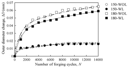
Figure 13.
Variation in the specimen outer diameter change (near the working surface) by number of forging cycles. (150/180—Forging load (kN), WL—With Lubrication, WOL—Without Lubrication).
3.4. Interrelation among Evaluated Parameters
The relationship between the total center displacement, Z + ΔH, and the downward displacement, Z, is shown in Figure 14. A linear relationship with a slope of 2 was identified between the two parameters, regardless of the load or lubrication condition. Even though the vertical deformation varies by load, it was not affected by lubrication. It was identified that the downward displacement occurred with the same rate against the average height change throughout the experiment.
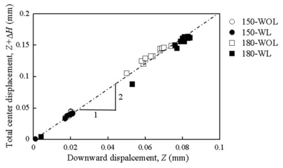
Figure 14.
Relationship between the total center displacement and downward displacement. (150/180—Forging load (kN), WL—With Lubrication, WOL—Without Lubrication).
Figure 15 shows the relationship between the outer diameter change, ΔD, and the total center displacement, Z + ΔH. A linear relationship was observed between the two parameters at the low deformation stage, for both lubrication conditions. As the deformation progresses, the effect of lubrication on the relationship between the parameters can be observed. Radial deformation showed a larger variation than vertical deformation at higher loads. The vertical shifting of the plots signifies the difference in deformation shape, namely, uniform radial deformation near the surface or bulging at 2 mm to 4 mm below the working surface. A large ΔD value is obtained at the same value of Z + ΔH since the bulging is a more localized deformation restricted by friction on the surface.
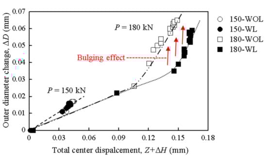
Figure 15.
Relationship between the outer diameter change (near the working surface) and total center displacement. (150/180—Forging load (kN), WL—With Lubrication, WOL—Without Lubrication).
Figure 16 shows the relationship between the compressive residual stress change at the center, Δσ and the total center displacement, Z + ΔH. A positive relationship was observed between parameters. Even though the effect of forging load was clearly observed, the effect of lubrication was not identified.
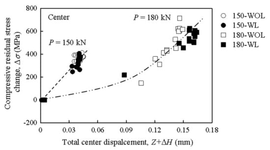
Figure 16.
Relationship between the compressive residual stress change and total center displacement. (150/180—Forging load (kN), WL—With Lubrication, WOL—Without Lubrication).
Figure 17 illustrates the relationship between the surface roughness change at the center, ΔRa, and the total center displacement, Z + ΔH. A positive relationship was observed for all of the forging conditions. At lower loads, an effect of lubrication was not observed. As the load increased, the specimen with lubrication showed less surface roughness change for the similar deformation as the ‘without lubrication’ specimen. It is found from Figure 11, Figure 12, and Figure 14 that the lubrication makes the specimen deformation easier. Therefore, the radial sliding and deformation on the surface under the ‘with lubrication’ condition are considered to be larger than under the ‘without lubrication’ condition. On the contrary, surface oxidation intensely occurred without lubrication and the oxide increased the friction on the surface and its wear and abrasion, resulting in increased surface roughness. The different curves for the 180 kN load condition may have been caused by oxidation.
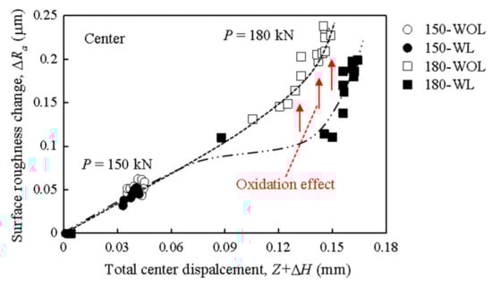
Figure 17.
Relationship between the surface roughness change and total center displacement. (150/180—Forging load (kN), WL—With Lubrication, WOL—Without Lubrication).
Figure 18 shows the schematic of specimen deformation during the experiment. During loading, the material on the specimen surface moves outward (radial displacement), and the height of the specimen is reduced due to deformation that is caused by the applied load. Radial deformation occurs and the surface extended outward uniformly when the lubrication is present and works properly. On the other hand, the ‘without lubrication’ condition caused high friction and restricted the radial deformation on the surface, resulting in barrel-shaped deformation near the working surface. The deformed surfaces try to return to the original position as the specimen releases the contact with the counter face. A downward displacement at the center occurs and compressive residual stress is generated on the working surface since the material cannot move to the original position due to the plastic deformation and high-contact pressure at the center. Higher compressive residual stress and surface roughness were observed at the center for all forging conditions due to the downward deformation at the center of the specimens.
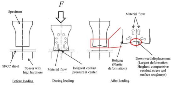
Figure 18.
Schematic of the specimen deformation during the experiment.
Table 3 presents a summary of the results. An increase in the forging load resulted in a large positive effect on surface roughness, compressive residual stress, downward displacement, average height change, and outer diameter change. On the other hand, lubrication does not show a large effect on the above parameters. The presence of lubrication during forging showed a small negative effect on surface roughness, compressive residual stress, and outer diameter change, while showing a small positive effect on average height change and downward displacement. Analysis of the overall results shows that the effect of the magnitude of the forging load on the discussed parameters is large when compared to the effect of the lubrication condition.
Table 3.
Summary of the results.
Fatigue, wear, and overload are the three leading causes of forging tool failure. The failure due to fatigue and wear occurs as a result of continuous use of the tool. The initiation of the failure most probably starts from the point with the largest deformation or abrasion. Table 4 shows the effects of increases in the analyzed parameters on forging tool life and forged part accuracy. Generally, surface roughness, Ra, increase has a negative effect on tool life, because the rough surface stimulates the initiation of cracks on the surface and increases the wear rate. Moreover, oxidation on the working surface of the tool, which is a reason for surface roughness, Ra, increase, considerably reduces the tool life [36]. Therefore, forging at higher loads without lubrication, which increases the surface roughness, Ra, will lead to a reduction in tool life when compared to forging at a moderate load with lubrication. It is known that compressive residual stress, σ, positively affects fatigue life, fracture strength, and stress corrosion. Fatigue is one of the main causes of forging tool failure. Therefore, an increase in compressive residual stress, σ, during forging will have a favorable effect on tool life. Deformation on the forging tool, which is represented by parameters Z, ΔD, and ΔH, reduces the tool life by creating a favorable environment for crack initiation. Furthermore, large deformation on tools causes defects on the forged product; thus, tools need to be removed from production before failure occurs by fracture or wear. Surface roughness, Ra, increase has a negative effect, even though compressive residual stress, σ, increase in the forging tool during operation causes no effect on product accuracy, because cold forging is mainly used for the production of net or near- net shape products, which required useable surface after forging. Deformation (Z, ΔD, and ΔH) in the tool will generally negatively affect the accuracy of the forged product. When considering the above facts, designing the forging process in such a way that the forging tools are operated with moderate forging loads under with lubrication conditions will accuracy increase the tool life of the forging tool and product, when compared to forging tools operated with high loads under no lubrication conditions.
Table 4.
Effects of increase in analyzed parameters on forging tool life and forged part accuracy.
4. Conclusions
A cold forging upsetting process was carried out with specimens that were made of heat-treated SKH51 (59–61 HRC) material as the punch, under ‘with lubrication’ and ‘without lubrication’ conditions, with two different forging loads. The influences of lubrication and forging load on surface roughness, residual stress, and specimen deformation were studied. The main findings can be listed, as below:
- The forging conditions greatly influence changes in surface compressive residual stress, surface roughness, and deformation of the forging tools during operation. There is a positive relationship between the forging load and all of the above parameters (surface compressive residual stress, surface roughness, and tool deformation).
- The presence of lubricant during the forging process reduces the increase in surface compressive residual stress and surface roughness of the tool. A uniform distribution of compressive residual stress or surface roughness is not present on the working surface of the tool, for a higher forging load.
- The use of lubricant in forging changes the deformation behavior of the tools and surface condition deterioration. The downward displacement at the center has a positive linear relationship with average height reduction. The presence of lubrication changes the deformation behavior at higher loads.
- The surface roughness change depends on both the forging load and lubrication conditions, but compressive residual stress change largely depends only on forging load.
- The use of lubricant and a moderate forging load will lead to an increase in the tool life, when compared to forging without lubrication (dry forging) at high forging loads. Furthermore, the results of this study can be used in forging tool design and decisions regarding surface treatment conditions, in order to improve the tool life and product quality.
Author Contributions
Conceptualization, N.K., N.T. and T.U.; methodology, N.K.; software, R.H.; validation, N.K., R.H. and T.U.; formal analysis, N.K. and R.H.; investigation, N.K.; resources, M.F., Y.O. and M.K.; data curation, N.K.; writing—original draft preparation, N.K.; writing—review and editing, N.T., and T.U.; supervision, N.T.
Funding
This research received no external funding.
Conflicts of Interest
The authors declare no conflict of interest.
References
- Merklein, M.; Andreas, K.; Engel, U. Influence of machining process on residual stresses in the surface of cemented carbides. Procedia Eng. 2011, 19, 252–257. [Google Scholar] [CrossRef]
- Geiger, M.; Arbak, M.; Engel, U. Material adapted tool design in cold forging exemplified by powder metallurgical tool steels and industrial ceramics. Prod. Eng. 2008, 2, 409–415. [Google Scholar] [CrossRef]
- Ku, T.W.; Kang, B.S. Hardness-controlled tool fabrication and application to cold forging of inner race with skewed ball grooves. Int. J. Adv. Manuf. Technol. 2014, 74, 1337–1354. [Google Scholar] [CrossRef]
- Jarfors, A.E.; Castagne, S.J.; Danno, A.; Zhang, X. Tool wear and life span variations in cold forming operations and their implications in micro forming. Technologies 2017, 5, 3. [Google Scholar] [CrossRef]
- Abdullah, A.B.; Samad, Z. Cold forging die design: Recent advanced and future trends. J. Appl. Sci. 2007, 7, 868–876. [Google Scholar]
- Kramer, P.; Groche, P. Friction measurement under consideration of contact conditions and type of lubricant in bulk metal forming. Lubricants 2019, 7, 12. [Google Scholar] [CrossRef]
- Caminaga, C.; Neves, F.O.; Gentile, F.C.; Button, S.T. Study of alternative lubricants to the cold extrusion of steel shafts. J. Mater. Process. Technol. 2007, 182, 432–439. [Google Scholar] [CrossRef]
- Gariety, M.; Ngaile, G.; Altan, T. Evaluation of new cold forging lubricants without zinc phosphate precoat. Int. J. Mach. Tools Manuf. 2007, 47, 673–681. [Google Scholar] [CrossRef]
- Vollertsen, F.; Schmidt, F. Dry metal forming: Definition, chances and challenges. Int. J. Precis. Eng. Manuf. Technol. 2014, 1, 59–62. [Google Scholar] [CrossRef]
- Martinez Krahmer, D.; Hameed, S.; Sánchez Egea, A.J.; Pérez, D.; Canales, J.; López de Lacalle, L.N. Wear and MnS layer adhesion in uncoated cutting tools when dry and wet turning free-cutting steels. Metals 2019, 9, 556. [Google Scholar] [CrossRef]
- Herrmann, M.; Schenck, C.; Kuhfuss, B. Graded structured tools for dry rotary swaging. Dry Met. Form. 2018, 4, 18–24. [Google Scholar]
- Hafis, S.M.; Ridzuan, M.J.M.; Rahayu, A.; Mohamed, A.R.; Farahana, R.N.; Syahrullail, S. Minimum quantity lubrication in cold work drawing process: Effects on forming load and surface roughness. Procedia Eng. 2013, 68, 639–646. [Google Scholar] [CrossRef][Green Version]
- Andreas, K.; Merklein, M. Influence of surface integrity on the tribological performance of cold forging tools. Procedia CIRP 2014, 13, 61–66. [Google Scholar] [CrossRef][Green Version]
- Mckelvey, S.A.; Fatemi, A. Effect of forging surface on fatigue behavior of steels: A literature review. In Proceedings of the 28th Forging Industry Technical Conference, Chicago, IL, USA, 5–7 April 2011. [Google Scholar]
- Souza, T.; Pereira, M.; de Souza, R. Effect of Roughness on the Wear of Cold Forming Tools; SAE Technical Paper; SAE International: Warrendale, PA, USA, 2016. [Google Scholar]
- Syahrullail, S.; Azwadi, C.S.N.; Abdul Kadir, M.R.; Shafie, N.E.A. The effect of tool surface roughness in cold work extrusion. J. Appl. Sci. 2011, 11, 367–372. [Google Scholar]
- Martinez Krahmer, D.; Polvorosa, R.; López de Lacalle, L.; Alonso-Pinillos, U.; Abate, G.; Riu, F. Alternatives for specimen manufacturing in tensile testing of steel plates. Exp. Tech. 2016, 40, 1555. [Google Scholar] [CrossRef]
- Kloos, K.H. Residual stresses, definition and causes of generation. Z. Werkstofftech. 1979, 10, 293–302. [Google Scholar] [CrossRef]
- Czan, A.; Holubjak, J.; Daniš, I.; Martinček, J.; Mikloš, M.; Čep, R.; Hatala, M.; Malotova, Š. Analysis of residual stress in subsurface layers after precision hard machining of forging tools. MATEC Web Conf. 2018, 157, 01005. [Google Scholar] [CrossRef][Green Version]
- Del Pozo, D.; López de Lacalle, L.N.; López, J.M.; Hernandez, A. Prediction of press/ die deformation for an accurate manufacturing of drawing dies. Int. J. Adv. Manuf. Technol. 2008, 37, 649–656. [Google Scholar] [CrossRef]
- Rosochowski, A. Die compensation procedure to negate die deflection and component springback. J. Mater. Process. Technol. 2001, 115, 187–191. [Google Scholar] [CrossRef]
- Jurči, P.; Dlouhý, I.; Priknerová, P.; Mrštný, Z. Effect of sub-zero treatment temperatures on hardness, flexural strength, and fracture toughness of vanadis 6 ledeburiticdie steel. Metals 2018, 8, 1047. [Google Scholar] [CrossRef]
- Chang, S.H.; Lee, S.C.; Tang, T.P. Effect of shot peening treatment on forging die life. Mater. Trans. 2008, 49, 619–623. [Google Scholar] [CrossRef]
- Harada, Y.; Fukauara, K.; Kohamada, S. Effects of microshotpeening on surface characteristics of high-speed tool steel. J. Mater. Process. Technol. 2008, 201, 319–324. [Google Scholar] [CrossRef]
- Popp, U.; Engel, U. Microtexturing of cold forging tools - Influence on tool life. Proc. Inst. Mech. Eng. B J. Eng. Manuf. 2006, 220, 27–33. [Google Scholar] [CrossRef]
- Krajewski, M.; Brzozka, K.; Lin, W.S.; Lin, H.M.; Tokarczyk, M.; Borysiuk, J.; Kowalskia, G.; Wasik, D. High temperature oxidation of iron-iron oxide core-shell nanowires composed of iron nanoparticles. Phys. Chem. Chem. Phys. 2016, 18, 3900–3909. [Google Scholar] [CrossRef] [PubMed]
- Ghasemi, H.M.; Furey, M.J.; Kajdas, C. Surface temperatures and fretting corrosion of steel under conditions of fretting contact. Wear 1993, 162, 357–369. [Google Scholar] [CrossRef]
- Labašová, E. Measurement of Changes of the Surface Roughness in Sliding Area. Am. Int. J. Contemp. Res. 2013, 3, 1–2. [Google Scholar]
- Herai, T.; Ejima, M.; Yoshida, K.; Miyauchi, K.; Ike, H. Frictional surface damage and its mechanism in metal sheets. Sci. Pap. Inst. Phys. Chem. Res. 1978, 72, 1–13. [Google Scholar]
- Osakada, K.; Matsumoto, R. Fundamental study of dry metal forming with coated tools. CIRP Ann. Manuf. Technol. 2000, 49, 161–164. [Google Scholar] [CrossRef]
- Jianga, D.; Annéa, G.; Vleugelsa, J.; Vanmeensela, K.; Eeraertsb, W.; Liub, W.; Lauwersb, B.; Biesta, O.V. Residual stresses in hardmetals caused by grinding and EDM machining and their influence on the flexural strength, Powder Metallurgical High Performance Materials. In Proceedings of the 16th International Plansee Seminar, Reutte, Austria, 30 May 2005; Volume 2, pp. 1075–1085. [Google Scholar]
- Williams, J.A.; Dwyer-Joyce, R.S. Modern Tribology Handbook (Principles of Tribology); CRC Press: Boca Raton, FL, USA, 2001; Volume 1. [Google Scholar]
- Natori, M.; Song, S.; Sugimoto, K. The effects of fine particle peening on surface residual stress of a TRIP-aided bainiticferrite steel. J. Soc. Mater. Sci. 2014, 63, 662–668. [Google Scholar] [CrossRef]
- Timoshenko, S.P.; Goodier, J.N. Theory of Elasticity, 1st ed.; McGraw-Hill Book Company: New York, NY, USA, 1951. [Google Scholar]
- Malayappan, S.; Narayanasamy, R. An experimental analysis of upset forging of aluminum cylindrical billets considering the dissimilar frictional conditions at flat die surfaces. Int. J. Adv. Manuf. Technol. 2004, 23, 636–643. [Google Scholar] [CrossRef]
- Barrau, O.; Boher, C.; Vergne, C.; Rezai-Aria, F.; Gras, R. Investigations of friction and wear mechanisms of hot forging tool steels. In Proceedings of the 6th International Conference on Tooloing, Karlstad, Sweden, 10–13 September 2002. [Google Scholar]


© 2019 by the authors. Licensee MDPI, Basel, Switzerland. This article is an open access article distributed under the terms and conditions of the Creative Commons Attribution (CC BY) license (http://creativecommons.org/licenses/by/4.0/).