Article

The Analytical Model of Stress Zone Formation of Ti6Al4V/AA1050/AA2519 Laminate Produced by Explosive Bonding

1
Faculty of Mechanical Engineering, Military University of Technology, 2 gen. S. Kaliskiego str., 00-908 Warsaw, Poland
2
Faculty of Mechanical Engineering, University of Technology, 45c Wiejska str., 15351 Bialystok, Poland
3
Faculty of Mathematics, Physics and Technology, Kazimierz Wielki University, 30 J. K. Khotkiewicha str., 85064 Bydgoszcz, Ukraine
4
Faculty of Civil Engineering and Design, Lutsk National Technical University, 75 Lvivska Str., 43018 Lutsk, Ukraine
*
Author to whom correspondence should be addressed.
Metals 2019, 9(7), 779; https://doi.org/10.3390/met9070779
Submission received: 27 June 2019 / Accepted: 10 July 2019 / Published: 12 July 2019
(This article belongs to the Special Issue Explosive Welding)

Abstract

:
This paper contains an analytical description of the deformation of the upper layer AA2519/AA1050/Ti6Al4V laminate produced by an explosive bonding method. The basic parameters of the explosive welding process that influence the quality of the bonding are the detonation velocity of the explosive, the explosion energy, and the impact angle of the combined materials. The developed description uses the theory of elastodynamic character of materials deformation at the connection point due to local traction load. The presence of high pressure during joining was limited to the region where the plane surface moving with a constant subsonic velocity. An analytical description of the residual stresses distribution was also a performer. Results of analytical investigations were verified by structure examination of the bond zone. The work was supplemented by the chemical composition analysis of the base materials and a monotonic stretching test characterizing the basic mechanical properties of the produced laminate.

1. Introduction

Explosive welding is a process of great technological importance to the possibility of modern metal composite production. It is an important complement to traditional plating production methods, such as welding or rolling mill. Bimetals obtained this way, and multilayered composites consisting of more than two materials, have unique structural properties [1,2]. They are characterized by high strength, corrosion resistance and, in case of the association of appropriate materials, also a large ballistic resistance. Materials connectable by conventional methods can be explosion-bonded. It is also possible with metals and their alloys, for which traditional technology has no alternative. Combined materials can vary significantly in their properties, for example, steel–aluminum, steel–titanium, or aluminum–titanium [3,4,5]. Research of a question of welding by explosion concerns a significant amount of works, the majority from which have experimental character. Until 1967 it has been allocated such basic directions of research of this process:
1. Problems of a choice of the energy carrier and experimental research of high-speed blow of bodies;
2. Studying of the mechanical phenomena which occur on actions of the high-speed blow of bodies, in particular, a formation of a wavy surface;
3. Metal-physics processes which occur in materials at a high-speed blow.
Since then, decisions of problems of welding by the explosion has tested considerable progress. In particular, Cowan et al. [6] have learned a question of transition from wavy to a flat surface on the basis of hydrodynamic models, having offered Reynolds’ specific number for welding by an explosion. In further, scientific studies [7] on the basis of experimental researches communication of this number of Reynolds as well with a corner of collision of bodies is received. In work [8], these results were used for experimental and numerical modelling of the process of welding by the aluminum explosion to aluminum. It is determined that, during welding, the collision corner insignificantly differs from the initial. For this pair, the corresponding lays in limits 5–25°. They posited the relationship between the angle of collision and process parameters on the basis of hydrodynamic models. In [9] they studied the aspects of the interaction energy materials during welding explosion and shown on the correlation between the loss of kinetic energy and characteristics of welded elements. However, in a previous study on the analysis of the action rolling load on the elastic half-space, they found that these effects in wave-like connection limits bodies generally caused by the formation of elastic waves under the said load at a certain angle. The upper plate under the shock undergoes plastic deformation, lean on a substrate and “solidification,” that is, gaining form on the substrate surface and, further, no load (blast went on) undergoes elastic deformation caused by the influence of substrate only [10]. Thus, to complete these studies, one should examine the behavior of the upper plate during welding explosion. The action of the blast wave is difficult to assess its impact on the material, as known for certain pressure at a particular point in time and its spatial distribution. Some works, to overcome this uncertainty, used the integrated features, including deformation pulse pressure [11], but it does not fundamentally solve the overall problem. Additionally, not knowing exactly which model describes the behavior of real materials under impulsive load or partial load, it is known [12], the structure of the material may undergo significant changes. Therefore, this study, based on calculations made from Finite Element Method, proposes elementary “chain” model of deformation of the upper plate, which makes it possible to link angle collision explosion welding of mechanical characteristics material; also, the estimation of the impact surface waviness connections on the distribution of residual stresses in lower-plate basis [13].

2. Materials and Methods

The tests involved a layered composite formed by explosion welding of base materials in the form of AA2519 aluminum alloy and Ti6Al4V titanium alloy with the intermediate layer of AA1050 alloy in Figure 1. The presented merger process was carried out in the company Explomet (Opole, Poland), which is one of the few companies in the world involved in the commercial joining of materials by explosive bonding. The company has extensive experience, supported by numerous production implementations and patents.
Basic mechanical properties and chemical composition of the alloys combined were obtained and are presented in Table 1, Table 2 and Table 3. The scope of tests included testing on samples made of laminate AA2519/AA1050/Ti6Al4V combine explosive welding method.
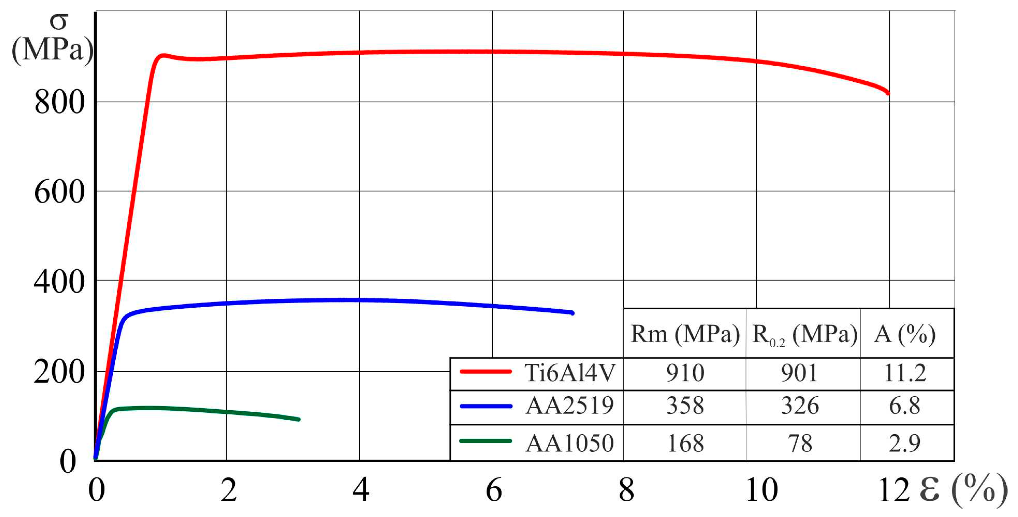
The basic strength properties of the laminate were determined on the basis of the monotonic stretching test. Tensile tests were carried out for flat samples in accordance with PN-EN ISO 6892-1: 2010. The monotonic stress–strain curves obtained for the base materials of the AA2519/AA1050/Ti6Al4V composite laminate in the postproduction state are shown in Figure 2. The tests were carried out on base materials used for combining the explosive laminate: Aluminum alloy AA2519 (AlCuMgMn + ZrSc) and titanium alloy Ti6Al4V. The laminate consists of basic materials with a thickness of 4.7 mm each. An additional layer of 0.6-mm-thick AA1050 alloy was required for the explosive welding process.
Graphs of the waveforms in the resultant drawing of the core materials are in Figure 3. In the case of tobacco retention, a tensile strength Rm = 910 MPa is obtained, which is the most tensile AA2519 (Rm = 358 MPa) over 2.5 times. The relative elongation A for Ti6Al4V titanium alloy is approximately 11.2%, while for AA2519 aluminum alloy, it is approximately 6.8%.
The tensile strength Rm of the laminated materials, whose base materials have a continuous structure obtained as a result of the monotonic stretching, can be compared with the theoretical composite strength calculated on the basis of the law of mixtures [14]. For the analyzed case of material AA2519-AA1050-Ti6Al4V this law describes the equation Rm = 606 MPa.
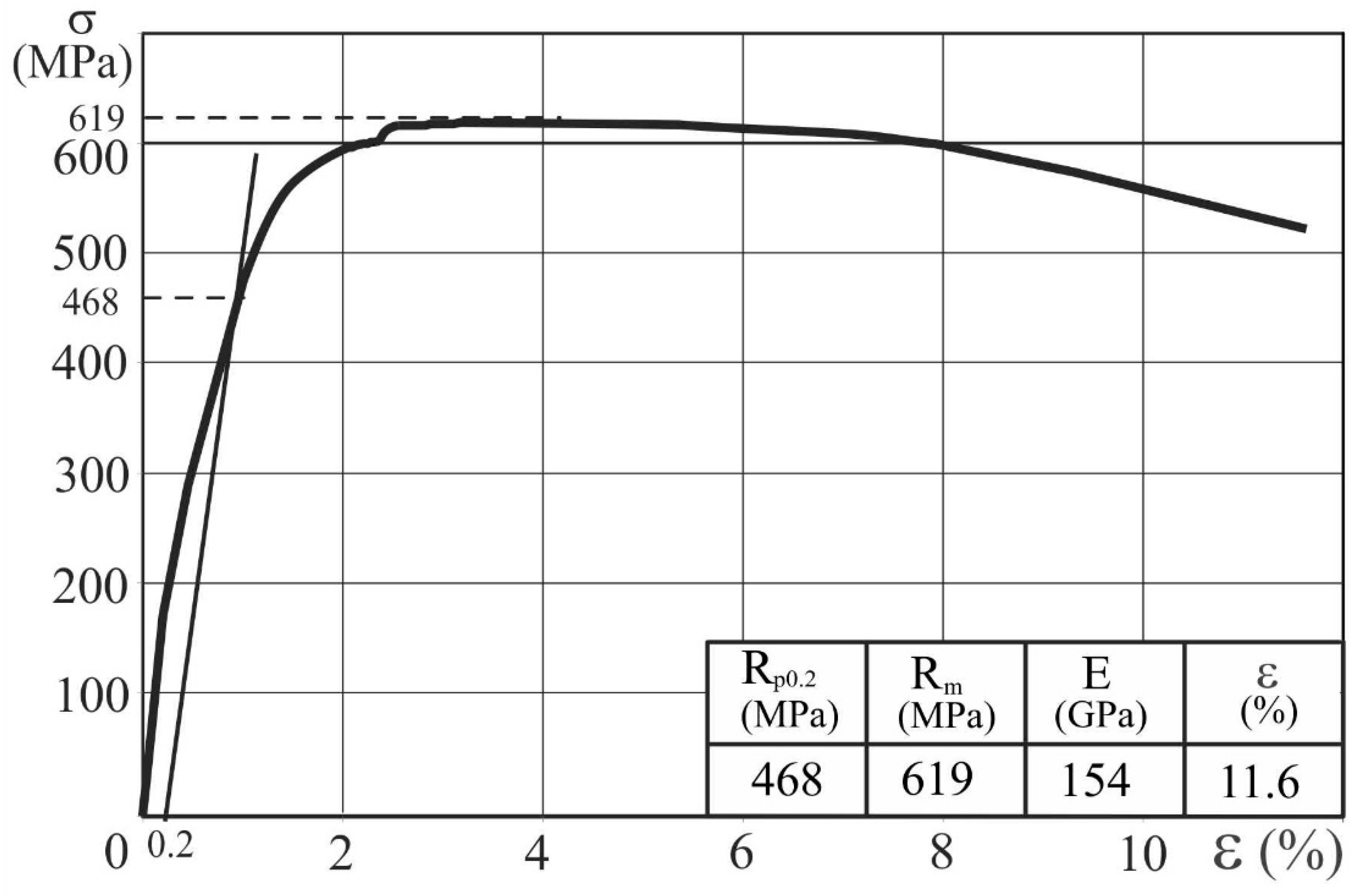
These curves are example of charts to verify the effect explosive welding has on the laminate (Figure 3).
The most striking result to emerge from the data is that tensile strength increased from 619 MPa after the combined explosive welding laminate. For AA2519/AA1050/Ti6Al4V composite laminate, the yield stress was defined as the stress corresponding to 0.2% permanent strain. After the explosive connection, the tensile strength of laminate increased by 13 MPa, which indicates the strengthening of the laminate [15].

3. Results

3.1. Simulation of Deformation Top of the Plate by Finite Element Method

Consider the deformation of the upper plate movable explosive loading, which for simplicity we replaced rigid movable punch. We assumed that the plate rests on a rigid base. The problem was modelled with finite element method. During the explosive bonding, the combined sheets collide at a certain angle, at least one of which, as a result of detonation of the explosive charge, reaches a speed of 1800–3000 m/s. The physical nature of achieving the required acceleration of the combined plates may vary. One can consider, for example, an electromagnetic pulse during magnetic bonding, energy of powder charge in the barrel of the weapon or explosion energy of an electric conductor under high voltage, but in all such cases, the process of collision of solid particles at high speeds is the same. In our own calculations only the mechanical processes occurring in the bottom plate were considered. The interaction of the boards was modeled by introducing a linearly distributed continuous load moving at a subsonic speed over the surface of the elastic two-dimensional substrate. Therefore, the problem was reduced to determine the extent of displacement of the load field (deformations) in the plane as a consequence of the deformation of the ground contour before the source of the moving load and under the surface of the bottom plate [16].
Solving this problem for elastic–plastic material is of significant value and speed of loading stress strength for slabs. In particular, the lack of speed of deformation or stress at high yield stress observed the formation of plate waves spreading through the plate change its configuration, so that there may be poorly welded areas. It can also cause the formation of uneven distribution that does not have detonated charge on the surface of the plate. This situation is the formation of elastic waves in front of the front loading of the top plate, shown in Figure 4.
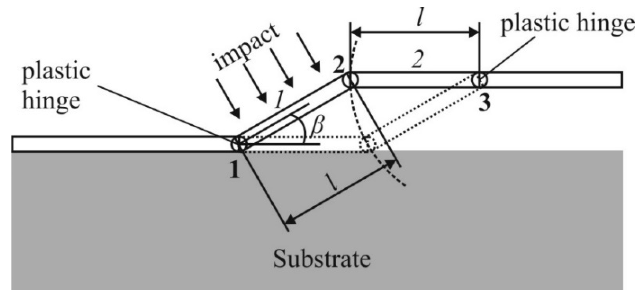
In one case represented on Figure 4, the basic loading predetermines high concentration of pressure on a plate site directly under loading. Thus, in the top and bottom parts of the inclined site, plate plastic hinges developed owing to what it caves in to a basis. However, the part which yet has not tested action mobile loading started to fluctuate practically as a membrane, on the brink of which set replaceable loading or changeable corner of returning. It obviously predetermines instability of a mode of welding as distribution of an elastic wave can change distribution of a charge to plate surfaces.
In Figure 5, it represents deformations of the top plate for its increased plasticity and the higher speed of movement of loading. It is visible, that character of deformation of a plate is something excellent. Its bent part in the middle will test smaller pressure, than on the ends, where plastic hinges are developed. Additionally, the plastic hinges are developed on a rectilinear site of a plate to which the blast wave is yet cunning. Wave effects in this part of the top plate were not observed owing to high plasticity and the increased speed of movement of loading.
Corresponding character of deformation of the top part of a plate were similar to a double bend on plastic hinges. It generated the following simplified analytical model of deformation of the top plate at welding by explosion.

3.2. The Simplified Analytical Model of Deformation of the Top Part of Preparation

It was assumed that, under the influence of an explosive impulse on the ends of the inclined part of one top plate, plastic hinges 1 and 2 were developed (Figure 6). Additionally, owing to a bend from the action of an explosive crush on the end of a part 2 horizontal sites also the plastic hinge 3 is developed. The length sites 2 is selected same, as well as sites 1 as the corner of an inclination of a plate during welding by explosion remains practically constant that is confirmed by experiments [8].
Taking into account the action of forces of inertia and small times of explosive impulses, we will consider that the site 2 is practically not deformed. At the same time, the end two sites of one plate should pass a way outlined by a piece of an arch with the center in a point 3 and radius (a shaped arch on Figure 5). Technological aspects of explosive bonding impose the use of materials susceptible to deformation in the surface layer. Thus, considering action of an explosive impulse we consider, that this site does not lose firmness in a longitudinal direction. Depending on a polar corner these deformations will be defined by an obvious geometrical parity:
Δ l l = 1 c o s θ c o s ( β θ ) + 2 c o s θ c o s ( β θ ) ( 1 + c o s β ) c o s β ( c o s β 2 )
It is obvious, that the maximum value of Equation (1) will get, in case of a polar corner, θmax = β/2. Having substituted this value in Equation (1) we will receive
δ Δ l l | ( 1 c o s β 2 ) θ = θ m a x m a x
Thus, on the basis of Equation (2) we will receive such estimated approach for a collision β corner:
β = 2 a r c c o s ( 1 δ m a x 2 )
For minimum limit value of deformation we will accept δmax deformations at achievement of border of fluidity of a material. For maximum limit value, we will accept δmax experimentally received values of lengthening of the sample δd at dynamic loadings. Thus, we will receive such estimation of a corner of collision β of bodies at welding by explosion:
2 a r c c o s ( 1 σ Y 2 E ) < β < 2 a r c c o s ( 1 δ d 2 )
In particular, for aluminum AA1050, σY = 140 MPa, δd = δ50 = 0.05, and E = 68.3 GPa, so we will receive for a collision corner
5.2° < β < 25.7°
that is well coordinated from experimental data [2].

3.3. Research of Residual Pressure in a Lining by Means of the Finite Element Method (FEM)

In the drawings presented, more low-dynamic deformation of an elastic–plastic top plate (aluminum alloy AA2519) and filling of bends of a wavy connection border is represented in Figure 7 where it is visible that filling with the top plate of a wavy surface occurs owing to its plastic deformation. After the passage of a shock, wave of pressure quickly relax, and the form of the formed surface is stored. That is, the reference of the top plate reminds corresponding for liquids which answers experimental data.
For studying of residual pressure which arise in the bottom part of a plate we will consider flat deformation of the elastic layer which bottom surface lies on a rigid surface, and on the top, it is set to regional conditions of the second sort in movements which describe the corresponding wavy form of a surface. We investigate dependence of concentration of pressure Mises on the quantity of waves on unit of length of a layer for them of constant amplitude. Figure 8 represents the comparisons of dependences normalized by a certain rank of pressure Mises from distance between peaks of the waves, received by means of FEM. In model, 100,000 square linear elements were used for the purpose of the adequate description of the wavy form of a surface.
Figure 9 represents comparisons of dependences normalized by a certain rank of pressure Mises from distance between peaks of the waves, received by means of FEM. In model, 100,000 square linear elements were used for the purpose of the adequate description of the wavy form of a surface AA1050 and Ti6Al4V.
From Figure 5, Figure 6 and Figure 7, it is visible that the reduction of distances between tops of performances of a wavy surface of contact predetermines increase in concentration of pressure. At the same time, residual pressure with reduction of this distance extend deep into the sample, and their maximum values the plates localized near a surface, ever less.
Considering this, qualitative connection by explosion of two materials will occur when materials which incorporate are elastic–plastic, distance between tops of performances of a wavy surface are smaller, that provides localization of residual pressure near the internal border of a bimaterial. One more condition does not exceed the residual stresses on certain critical border.
On the basis of the analytically numerical models developed before determination, that close to the speed of a sound of speed of movement of loading, predetermine a desirable relief of a surface which provides better coupling of surfaces. Reduction of speed of movement of a blast wave increases distances between tops of performances of a wavy surface which reduces quality of welding.
Formulation and the scheme of the decision of a problem. We will consider a flat problem of thermoelasticity linearly anisotropic piecewise-homogeneous body (plate) that consists of two materials with rectilinear border of their division, the conditions of ideal mechanical and thermal contact united among themselves with maintenance. Obverse surfaces of a plate are believed to be thermally insulated. The body contains a crack of some initial length which during cyclic loadings starts to increase, yet will not reach the critical size and the plate will collapse. On the border of a plate and crack surfaces, certain thermal and mechanical regional conditions which provide quasistatic the problem decision on every cycle fatigue loadings are set.
According to [17], the formulated flat problems of heat conductivity and thermoelasticity are reduced to the decision of such regional integrated equations for definition of a flat temperature field
1 2 Σ θ ( y ) = Γ Θ * bm ( x , y ) Σ h n ( x ) d Γ ( x ) Γ H * bm ( x , y ) Δ θ ( x ) d Γ ( x ) , 1 2 Δ h n ( y ) = n i + ( y ) [ Γ Θ i * * bm ( x , y ) Σ h n ( x ) d Γ ( x ) Γ H i * * bm ( x , y ) Δ θ ( x ) d Γ ( x ) ]
and resultants of mechanical fields
1 2 Σ u i ( y ) = Γ U i j bm ( x , y ) Σ t j ( x ) d Γ ( x ) Γ T i j bm ( x , y ) Δ u j ( x ) d Γ ( x ) + Γ R i bm ( x , y ) Δ θ ( x ) d Γ ( x ) + Γ V i bm ( x , y ) Σ h n ( x ) d Γ ( x ) , 1 2 Δ t i ( y ) = n j + ( y ) [ Γ D i j k bm ( x , y ) Σ t k ( x ) d Γ ( x ) Γ S i j k bm ( x , y ) Δ u k ( x ) d Γ ( x ) +   Γ Q i j bm ( x , y ) Δ θ ( x ) d Γ ( x ) + Γ W i j bm ( x , y ) Σ h n ( x ) d Γ ( x ) ]
where xy are points of integration and collocation, respectively; hi components of a vector of density of a thermal stream; ui components of a vector of movements; θ temperature change compared with reference; ti = σijnj components of a vector of pressure; Σhn = hi + ni + hini; nj±; components of a vector of normals to n± surfaces Г±; nn+ = n; – the valid differential of arches which Г = UjГj model cuts (cracks) and body border. For all kernels of integrated parities Equation (6), Equation (7) received in the compact closed form in work [18].
It is necessary to underline, that singular integrals need to be calculated in the sense of a principal value, and hypersingular in sense of a Hadamard final part. If among contours is Гj closed for them it is necessary to consider [9], θ+ = θ, θ = 0, hn+ = hn, hn = 0, etc., that is in Equations (6) and (7); on the closed contours it is necessary to consider equality. Δθ = Σθ = θ, Σhn = Δhn = hn, Σtj = Δtj = tj, Δuj = Σuj = uj, Δθ = θ, Σhn = hn.
As offered in [9], the method of limiting elements gives the chance to solve systems of Equation (6) with high accuracy, Equation (7) and to define factors of intensity of pressure and thermal streams in crack tops on every cycle quasistatic thermal and mechanical loadings.
The integrated Equations (6) and (7) give the chance to consider directly thermal and mechanical regional conditions without introduction in consideration equivalent mechanical loadings (which adequacy is not accurately outlined) and is considerably the most accurate from methods existing on this time [17]. Besides, the Equations (6) and (7) are especially regional, that gives the chance to model growth cracks without the necessity of changing a grid of breakdown of an area, which in this case is simply absent. That is, the offered approach has essential advantages over finite element modelling of thermal fatigue [14].
Let us consider, that growth of each of crack tops occurs under law of Paris [19], that is, it can be described with such usual differential equation:
d a i = C p ( Δ K eff , i ) m p d N
where Cpmp—empirical steels of materials of a body (p = 1.2); ai—Nquantity of cycles of loading; i—length of a crack on iterations; ΔKeff,i—scope of effective value the Stress Intensity Factor-SIF on iterations i (we assume, that Keff = K1).
Considering that on every cycle, the crack receives discrete growth from each party, we will pass in Equation (8) from differentials to small sizes. For firmness of the scheme of a method of limiting elements, we will consider that the crack in one of the tops grows on each iteration in size which Δα0 is equaled to length of a limiting element of breakdown of a crack. Then, the quantity of cycles of loading which answers this gain, providing the given iteration, will be defined according to Equation (9) behind the formula
Δ N i = Δ a 0 C p ( Δ K eff , i ) m p
For same quantity of cycles, the second top will grow up on size
Δ a 1 , i = Δ a 0 C q ( Δ K eff , i ) m q C p ( Δ K eff , i ) m p
where q = 1.2, when crack tops are in one material, and qp when in the different.
Each iterations i to which Equation (10) quantity of cycles set by the formula answers, ΔNi the crack extends along a rectilinear site. A corner of advancement of a crack on the considered step we will define on the basis of criterion of a minimum of density of energy of deformation. These [7] which considers that cracking is directed in a body from top of thin defect lengthways directly, set by a polar corner for θx, which the factor of density S of energy of deformation gets minimum value (potential energy opposite behind a sign to power function, to that the maximum of power function answers a minimum of potential energy):
S θ | θ = θ *   =   0 ,   2 S θ 2 | θ = θ *   >   0
And the factor of density S of energy of deformation is function of only polar corner and the Stress Intensity Factor-SIF: S = S(θ, KI, KII).

4. Discussion

Basic to the problems of the definition of durability of products is study of the development of tiresome defects. A wide volume of research has been carried out on the development of tiresome cracks in isotropic and anisotropic bodies for actions of mechanical loadings. However, the influence of thermal fatigue on anisotropic materials remains still to be studied. The majority of research is described by cyclic thermal loading by means of equivalent mechanical [8] that, as usual, rather roughly outlines processes which run across thermoelastic materials. Therefore, it is important to investigate factors of intensity of pressure and a trajectory of advancement of tiresome cracks in the final piecewise-homogeneous plates made of anisotropic materials; after all, welding by explosion obviously changes properties of materials of components in perpendicular and parallel to border of division directions. Numerical analytical approach is put in a basis of recently developed boundary element method of functions of a jump [18] that gives the chance to study thermoelastic anisotropic bodies with bimaterial with breakdown use only body and surface (line) borders crack-like defect. It gives the chance to model effectively crack growth due to thermal fatigue for actions cyclic thermal loadings a method of step-by-step addition to the previous grid of limiting elements of the corresponding length in defect tops.
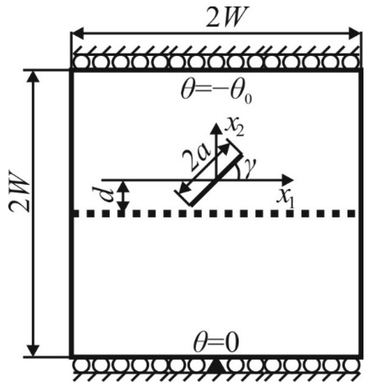
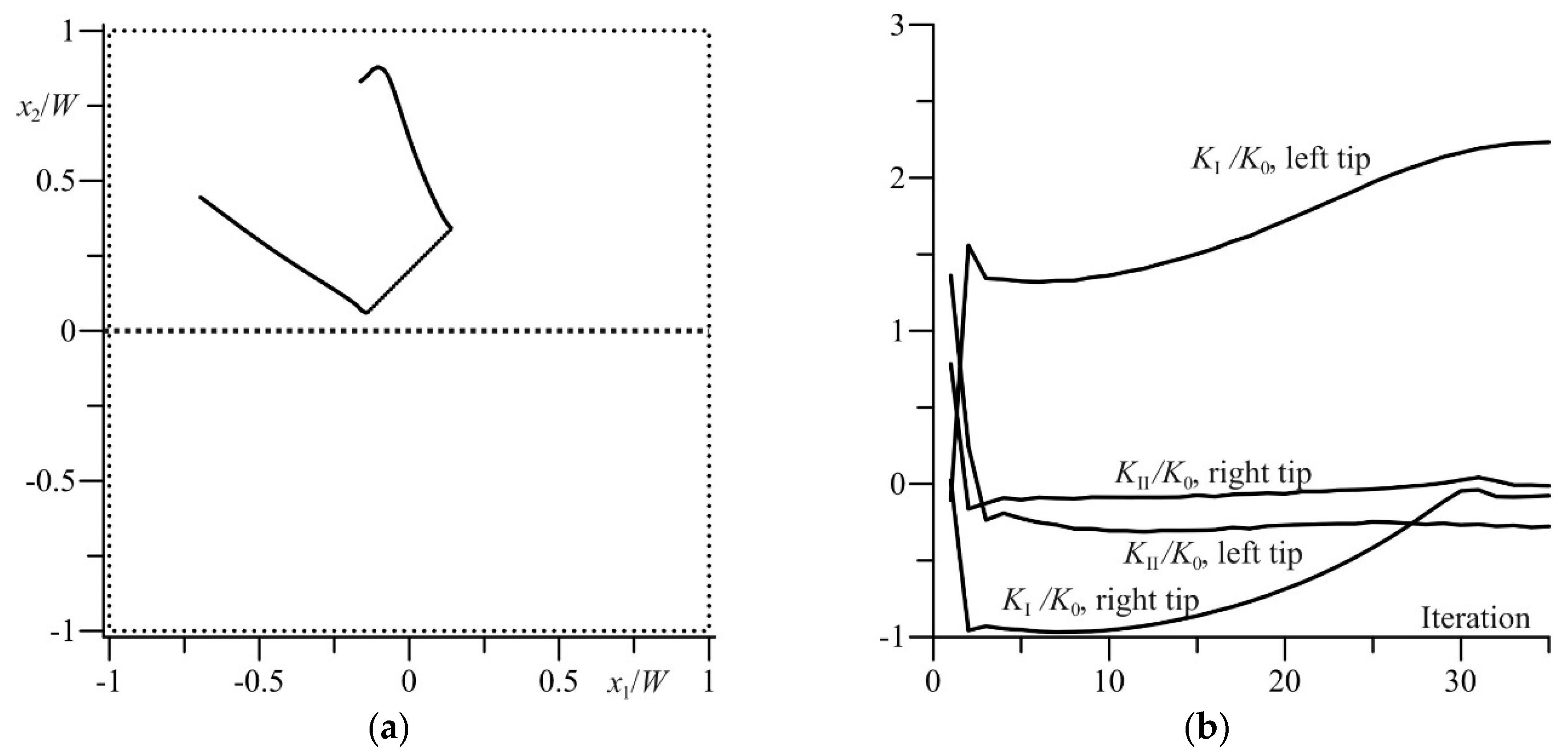
We will consider a square plate made with bimaterial with the party which 2W contains inclined under a corner to γ a horizontal a noncentral crack in length 2a. The distance from border of division of materials to a crack is equal to d. The crack center is located on an axis of symmetry of a plate (see the scheme in Figure 10). Properties of the top material of a plate are as such: E11 = 55 GPa, E22 = 21 GPa, v12 = 0.25, G12 = 9.7 Gpa. α1 = 6.3 × 10⁻⁶ K−1, α2 = 2 × 10⁻⁵ K−1, k11/k22 = 3.46/0.35. The bottom material of a plate is believed to be isotropic with such parameters: E = 1 GPa, v = 0.25, α = 10−5 K−1, (k11/k22 = 1/1 thermolayer). We will learn a trajectory of crack growth and the Stress Intensity Factor-SIF in a case, when γ = 45°, a = 0.2 W, d = 0.2 W, θ0 = 10 K. Initially the crack is located in the top part of a plate. Vertical lateral surfaces of a plate are thermally insulated and free from loadings, and horizontal are supported at different constant temperatures which cyclically vary. Besides, horizontal surfaces cannot move along a vertical direction (the mixed thermal and mechanical regional conditions).
In Figure 11 the calculated trajectory of the development of a crack and corresponding factors of intensity of pressure in its both tops in their dependence on quantity of iterations is represented. It is believed that on each iteration the crack grows in both tops on a constant Δα0 = 0.1α. The factor of rationing the Stress Intensity Factor-SIF is equal to K 0 = E 22 α 22 θ 0 π a where α initial semilength of the crack, and modules of elasticity and factors of thermal expansion answer properties of an anisotropic material.
From Figure 11, it is visible that difference of thermomechanical properties of materials essentially influences a trajectory of crack growth. In the left top, it sharply varies from an initial direction and in due course (in sense of quantity of cycles of loading) keeps away from division border practically rectilinearly. Instead of that, the trajectory of movement of the right top is not rectilinear and at first comes nearer to body border, and then starts to keep away from it. Thus, the Stress Intensity Factor-SIF of both fashions in the right top, something decrease.

5. Conclusions

On a basis, the elementary analysis is received estimations of a corner of collision which are well coordinated with experimental data. It testifies that a collision corner and, consequently, “a weldability window” mainly depend on mechanical properties of a material of the top plate. Certainly, optimum value of this corner depends on properties of both materials, and also from quality generated jet which requires the further research.
On the basis of the analysis of residual pressure in a plate of a basis which arise owing to «solidification» a material of the top plate at falling on bottom with formation of a wavy surface of connection, it is determined that residual pressure with distance reduction between tops of performances of a surface of connection are localized in a zone of a welded seam, and behind the module thus increase.
The cracks formed in materials increase for actions thermal fatigue loading and beat off division border. Thus, presence of technological defects can cause cracking a material from the connection welded by explosion.

Author Contributions

Conceptualization, I.S. and I.T.; methodology, L.S. and K.G.; formal analysis, I.S., I.P.; investigation, I.S., L.S. and H.S.; writing—original draft preparation, K.G., H.S., I.T., I.P.; writing—review and editing, I.S. and K.G.; supervision, L.S.

Funding

The project is carried out under Project PBS2/A5/35/2013 funded by the National Research and Development Centre.

Acknowledgments

I would like to thank Explomet from Opole, Poland for help in validating results and making connections for explosive connection of laminate AA2519/AA1050/Ti6Al4V.

Conflicts of Interest

The authors declare no conflicts of interest.

References

  1. Kosturek, R.; Wachowski, M.; Sniezek, L.; Gloc, M.; Sobczak, U. The effects of the heat treatment on the microstructure of Inconel 625/steel bimetal joint obtained by explosive welding. In Proceedings of the International Conference on Advanced Functional Materials and Composites (ICAFMC2018), MATEC Web of Conferences 242, Barcelona, Spain, 5–7 September 2018. [Google Scholar] [CrossRef]
  2. Rozumek, D.; Marciniak, Z. Fatigue tests of bimetal zirconium-steel made by explosive welding. Procedia Eng. 2016, 160, 137–142. [Google Scholar] [CrossRef]
  3. Wachowski, M.; Gloc, M.; Slęzak, T.; Plocinski, T.; Kurzydlowski, K.J. The Effect of Heat Treatment on the Microstructure and Properties of Explosively Welded Titanium-Steel Plates. J. Mater. Eng. Perform. 2017, 26, 945–954. [Google Scholar] [CrossRef] [Green Version]
  4. Prazmowski, M.; Rozumek, D.; Paul, H. Static and fatigue tests of bimetal Zr-steel made by explosivewelding. Eng. Fail. Anal. 2017, 75, 71–81. [Google Scholar] [CrossRef]
  5. Rozumek, D.; Banski, R. Crack growth rate under cyclic bending in the explosively welded steel/titaniumbimetals. Mater. Des. 2012, 38, 139–146. [Google Scholar] [CrossRef]
  6. Дерибас, А.А.; Кудинoв, В.М.; Матвеенкoв, Ф.И.; Симoнoв, В.А. Сварка взрывoм. Физика гoрения и взрыва 1967, 1, 111–118. [Google Scholar]
  7. Manikandan, P.; Hokamoto, K.; Deribas, A.; Raghukandan, K.; Tomoshige, R. Explosive Welding of Titanium, Stainless Steel by Controlling Energetic Conditions. Mater. Trans. 2006, 47, 2049–2055. [Google Scholar] [CrossRef]
  8. Cowan, G.R.; Holtzman, A.H. Flow Configurations in Colliding Plates: Explosive Bonding. J. Appl. Phys. 1963, 34, 928–939. [Google Scholar] [CrossRef]
  9. Szecket, A.; Inal, O.T.; Vigueras, D.J.; Rocco, J. A wavy versus straight interface in the explosive welding of aluminum to steel. J. Vac. Sci. Technol. 1985, 3, 2588–2593. [Google Scholar] [CrossRef]
  10. Grignon, F.; Benson, D.; Vecchio, K.S.; Meyers, M.A. Explosive welding of aluminum to aluminum: Analysis, computations and experiments. Int. J. Impact. Eng. 2014, 30, 1333–1351. [Google Scholar] [CrossRef]
  11. Hutsaylyuk, V.; Sulym, H.; Turchyn, I.; Asternak, J. Dissipative Structures Modeling in the Aluminium Alloy: An Energy Approach. In Proceedings of the 8th International Conference on Intelligent Technologies in Logistics and Mechatronics Systems, Panevezys, Lithuania, 23 May 2013. [Google Scholar]
  12. Лысак, В.И.; Кузьмин, С.В. Развитие представлений o нижней границе сварки металлoв взрывoм. Автoматическая сварка 2009, 11, 7–14. [Google Scholar]
  13. Haddar, N.; Fissolo, A.; Maillot, V.; Haddar, N. Thermal fatigue crack networks: An computational study. Int. J. Sol. Struct. 2005, 42, 771–788. [Google Scholar] [CrossRef]
  14. Nishida, M.; Minakuchi, K.; Anado, K.; Araki, T.; Hyodo, K. Fabrication of high-strength steel fiber reinforced metal matrix composites by explosive bonding and their tensile properties. Weld. Int. 1995, 9, 179–184. [Google Scholar] [CrossRef]
  15. Szachogluchowicz, I.; Sniezek, L.; Hutsaylyuk, V. Low cycle fatigue properties of AA2519-Ti6Al4V laminate bonded by explosion welding. Eng. Fail. Anal. 2016, 69, 77–87. [Google Scholar] [CrossRef]
  16. Lysak, V.I.; Kuzmin, S.V. Explosive Welding of Metal Layered Composite Materials; Paton Electric Welding Institute of NASU: Kiev, Ukraine, 2003; p. 117. [Google Scholar]
  17. Pasternak, I.; Pasternak, R.; Sulym, H. Pasternak Ia. Boundary integral equations and Green’s functions for 2D thermoelectroelastic biomaterial. Eng. Anal. Bound. Elements 2014, 48, 87–101. [Google Scholar] [CrossRef]
  18. Paris, P.; Erdogan, F.A. Critical analysis of crack propagation laws. J. Basic Eng. 1963, 85, 528–534. [Google Scholar] [CrossRef]
  19. Sih, G.C. Mechanics of Fracture Initiation and Propagation: Surface and Volume Energy Density Applied as Failure Criterion; Institute of Fracture and Solid Mechanics Lehogh University: Bethlehem, PA, USA, 1991. [Google Scholar]
Figure 1. Laminate of AA2519/AA1050/Ti6Al4V combined explosive welding method: (a) Connection area; (b) microhardness connection area.
Metals 09 00779 g001
Figure 2. Graphs of monotonic stretching of flat samples made of base materials of AA2519-AA1050-Ti6Al4V layer material.
Metals 09 00779 g002
Figure 3. Stress–strain diagram for AA2519/AA1050/Ti6Al4V combined explosive welding method.
Metals 09 00779 g003
Figure 4. The scheme of elementary “chain” model of deformation of the top plate.
Metals 09 00779 g004
Figure 5. Deformation of the top part of a plate under the influence of mobile loadings.
Metals 09 00779 g005
Figure 6. The scheme of elementary “chain” model of deformation of the top plate.
Metals 09 00779 g006
Figure 7. Dynamics of deformation of the upper alloy plate AA2519.
Metals 09 00779 g007
Figure 8. Distribution of pressure in AA1050 alloy.
Metals 09 00779 g008
Figure 9. Distribution of pressure in ground plate.
Metals 09 00779 g009
Figure 10. The problem scheme.
Metals 09 00779 g010
Figure 11. The trajectory of development of a crack (a) and the Stress Intensity Factor-SIF in its tops (b): K0—modulus of elasticity base material, K1—modulus elasticity top material, K11—elasticity modulus of the interlayer.
Metals 09 00779 g011
Table 1. Chemical composition of AA2519 alloy.
Chemical Composition (wt %)
SiFeCuMgZnTiVZrSc
0.060.085.770.180.010.040.120.20.36
Table 2. Chemical composition of Ti6Al4V alloy.
Chemical Composition (wt %)
OVAlFeHCN
<0.203.55.5<0.30<0.0015<0.08<0.05
Table 3. Chemical composition of AA1050 alloy.
Chemical Composition (wt %)
FeSiZnMgTiMnCu
0.4%<0.25<0.070.18<0.05<0.05<0.05