Article

Improvement of Damping Property and Its Effects on the Vibration Fatigue in Ti6Al4V Titanium Alloy Treated by Warm Laser Shock Peening

1
Institute of Advanced Manufacturing and Modern Equipment Technology, Jiangsu University, Zhenjiang 212013, China
2
Jiangsu Key Laboratory of Green Process Equipment, Changzhou University, Changzhou 213164, China
3
School of Mechanical Engineering, Jiangsu University, Zhenjiang 212013, China
4
School of Mechanical & Vehicle Engineering, Changzhou Institute of Technology, Changzhou 213002, China
*
Authors to whom correspondence should be addressed.
Metals 2019, 9(7), 746; https://doi.org/10.3390/met9070746
Submission received: 17 May 2019 / Revised: 20 June 2019 / Accepted: 25 June 2019 / Published: 3 July 2019

Abstract

:
In order to increase the vibration life of Ti6Al4V titanium alloy, warm laser shock peening (WLSP) is used to improve the damping properties and thus decrease the vibration stress in this study. Firstly, the Ti6Al4V specimens are treated by WLSP at different treatment temperatures from 200 °C to 350 °C. Then the damping ratios of untreated and WLSPed samples are obtained by impact modal tests, and the improvement of damping properties generated by WLSP is analyzed by the microstructures in Ti6Al4V titanium alloy. Moreover, the finite element simulations are utilized to study the vibration amplitude and stress during the frequency response process. Finally, the vibration fatigue tests are carried out and the fatigue fracture morphology is observed by the scanning electron microscope. The results indicate that the damping ratios of WLSPed specimens increase with the increasing treatment temperatures. This is because elevated temperatures during WLSP can effectively increase the α phase colonies and the interphase boundaries, which can significantly increase the internal friction of materials. Moreover, due to the increasing material damping ratio, the displacement and stresses during vibration were both reduced greatly by 350 °C-WLSP, which can significantly decrease the fatigue crack growth rate and thus improve the vibration fatigue life of Ti6Al4V titanium alloy.

Graphical Abstract

1. Introduction

Due to the high strength and fracture toughness, Ti6Al4V titanium alloy is widely used in the aerospace industry. However, the Ti6Al4V titanium alloy is always subjected to a failure under the service conditions of fatigue and vibration [1]. At present, traditional heat treatment methods generally use a temperature higher than the phase transition point to modify the material. This generally results in high residual tensile stress on the surface [2,3], which is not conducive to the improvement of fatigue life. Laser shock peening at room temperature (RT-LSP) has been proved to be an effective technology to improve the fatigue resistance of materials by the high compressive residual stress (CRS) [4,5]. The CRS induced by RT-LSP can effectively inhibit the initiation and development of cracks on the surface, which can decrease the fatigue crack growth rate [6,7]. Therefore, RT-LSP has been widely used in aeroengine blades, integral blade discs, turbine blades and other thin-walled structural parts [8], and can greatly prolong the service life of parts.
However, it has been confirmed that the CRS is subjected to a relaxation under cyclic loads, which will significantly reduce the improvement of fatigue performance [9,10]. Thermo-mechanical coupling effect is a technical means to control the strain-induced microstructures using thermal effects to obtain the required excellent microstructures and properties of materials [11]. Some researchers in Purdue University applied thermo-mechanical coupling technology to the field of laser shock peening, and put forward warm laser shock peening (WLSP). The thermal-mechanical coupling effect was used to optimize the microstructures on material surface treated by WLSP, so as to obtain more stable residual stress field and mechanical properties than RT-LSP, such as material strength, modulus of elasticity, fatigue strength, etc. [12,13]. Taking AA6061 aluminum alloy as the research object, Liao et al. [14] investigated the stability of CRS induced by RT-LSP and WLSP under cyclic loading. The results showed that the release rate of CRS induced by WLSP was much lower than that induced by RT-LSP under the same external cyclic loading. Ye [15] analyzed the microstructures in AISI4140 steel strengthened by WLSP. It was concluded that the dislocations produced during WLSP were stably pinned by the Cottrell atmosphere, which was generated by dynamic strain aging (DSA). Therefore, the microstructures generated by WLSP were extremely stable, which made the plastic strain in material not easy to release, so the release rate of CRS was much lower than RT-LSP. Moreover, Liao et al. [14] found a large amount of nanocrystalline precipitates in WLSPed AA6061 aluminum alloy, which can also stabilize the microstructure and thus decrease the release rate of CRS. Due to the CRS with high amplitude and stability, the fatigue life of AA6061 aluminum alloy and AISI4140 steel were significantly improved by WLSP.
At present, LSP and WLSP processing are mainly used to improve the traditional fatigue properties under low frequencies [16,17]. Nie studied the effects of RT-LSP impacts on the vibration life of TC6 titanium alloy under high frequencies [18]. It was found that the fatigue limit of vibration specimens was greatly improved by RT-LSP. However, the mechanism for fatigue life prolonging induced by RT-LSP/WLSP was still not clear. The effects of RT-LSP and WLSP on the vibration fatigue life under high frequencies still need to be investigated further. In particular, the effects of RT-LSP/WLSP processing on damping properties and their effects on the improvement of vibration fatigue life should be further studied.
In order to reveal the mechanism of vibration fatigue life extension induced by RT-LSP and WLSP, this study innovatively investigates the damping properties and their effects on the vibration displacement/stress/fatigue life of Ti6Al4V titanium alloy treated by RT-LSP and WLSP. The WLSP processing is conducted at different temperatures from 200 °C to 350 °C. Then the damping ratio and the vibration amplitude/stress are researched by impact modal tests and frequency response simulations. Moreover, the effects of RT-LSP and WLSP on the damping properties are analyzed by the microstructures in Ti6Al4V titanium alloy. Finally, the vibration fatigue life and its fracture morphology are measured to analyze the vibration fatigue improvement mechanism of WLSP.

2. Materials and Methods

2.1. Materials and Specimens

The material used in this study was Ti6Al4V (TC4) titanium alloy with the following chemical composition (in wt%): 6.5 Al, 4.20 V, 0.30 Fe, 0.28 Si, 0.02 C, 0.03 N, 0.02 H, 0.13 O and balance Ti. The mechanical properties of Ti6Al4V titanium alloy are shown in Table 1. The dimensions of Ti6Al4V specimens used in WLSP processing and impact modal tests were 250 mm × 30 mm × 2 mm with four boltholes for fixing, as shown in Figure 1.

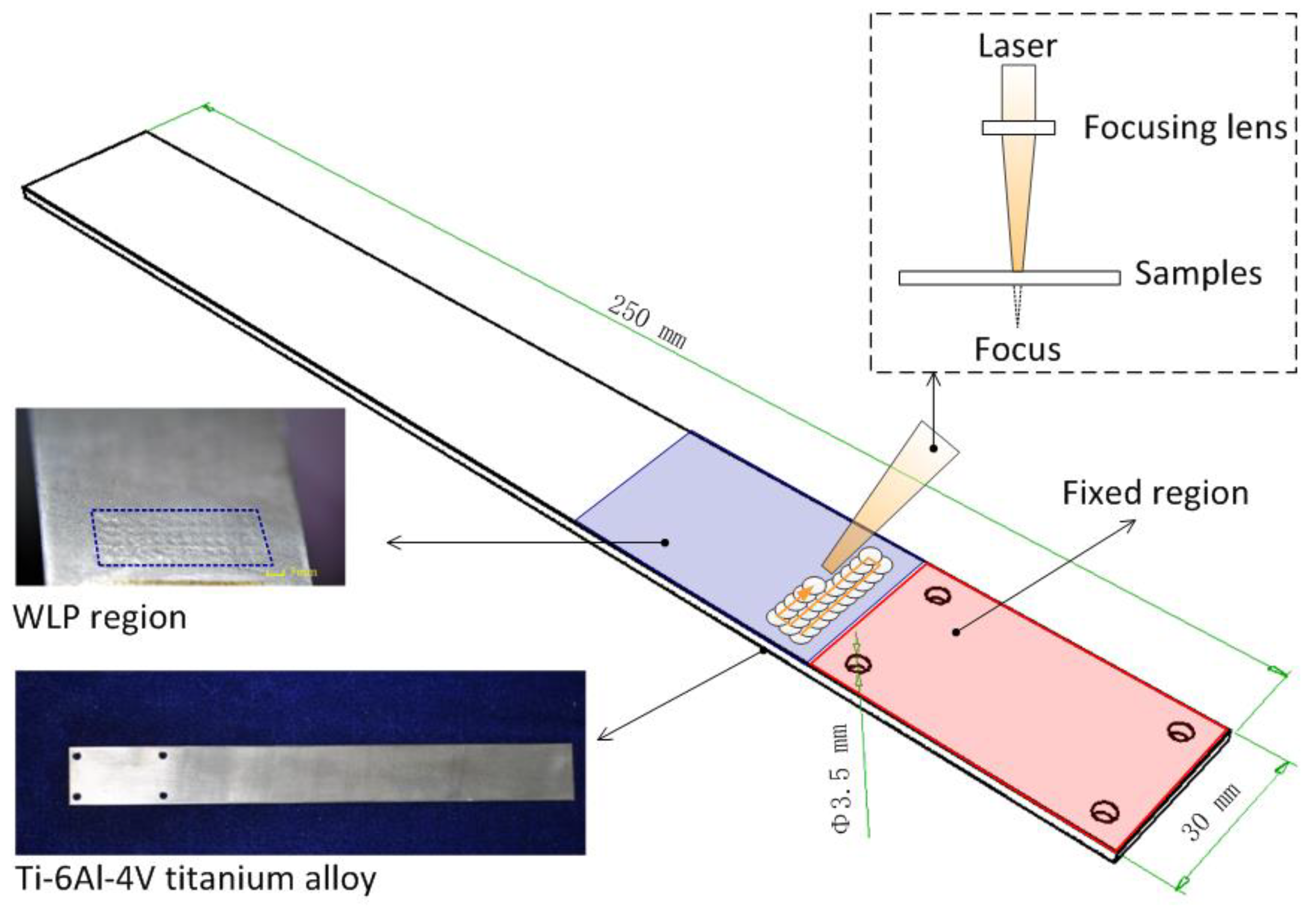
2.2. RT-LSP and WLSP Processing

The laser beam used in RT-LSP and WLSP was generated by a lamp-pumped Nd:YAG laser, the technical parameters of which can be seen in Table 2. During RT-LSP and WLSP processing, the samples were placed in front of the focus, as shown in Figure 1, and silicone oil was used as the confining medium due to its high vapor point. An aluminum foil with a thickness of 120 μm was used as the absorbing material. The laser spots with an overlap ratio of 50% were utilized and each sample was treated once. In addition, the WLSP experiments were carried out at elevated temperatures from 200 °C to 350 °C, which is in the regime of dynamic strain aging temperature [15]. The processing parameters used in RT-LSP and WLSP can be seen in Table 3. In the process of vibration, the deformation and stress of the specimen mainly occurred in the stress concentration zone at the fixed end, so RT-LSP and WLSP were only applied to the stress concentration area at the fixed end of specimens in this study. The RT-LSPed and WLSPed area with a size of 50 mm × 20 mm and the laser scanning paths are presented in Figure 1. In order to increase the performance, the RT-LSPed and WLSPed samples were all treated three times.

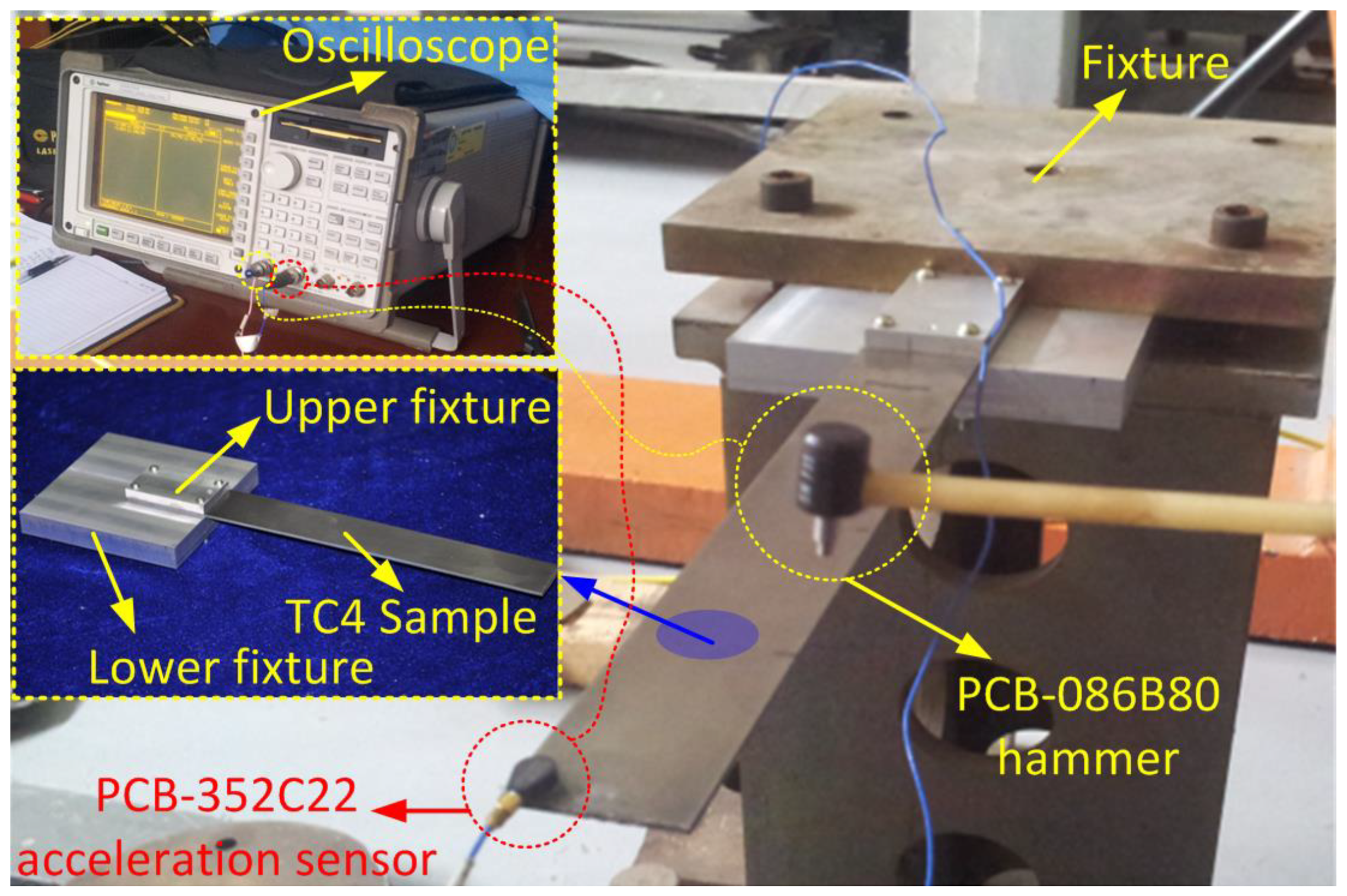
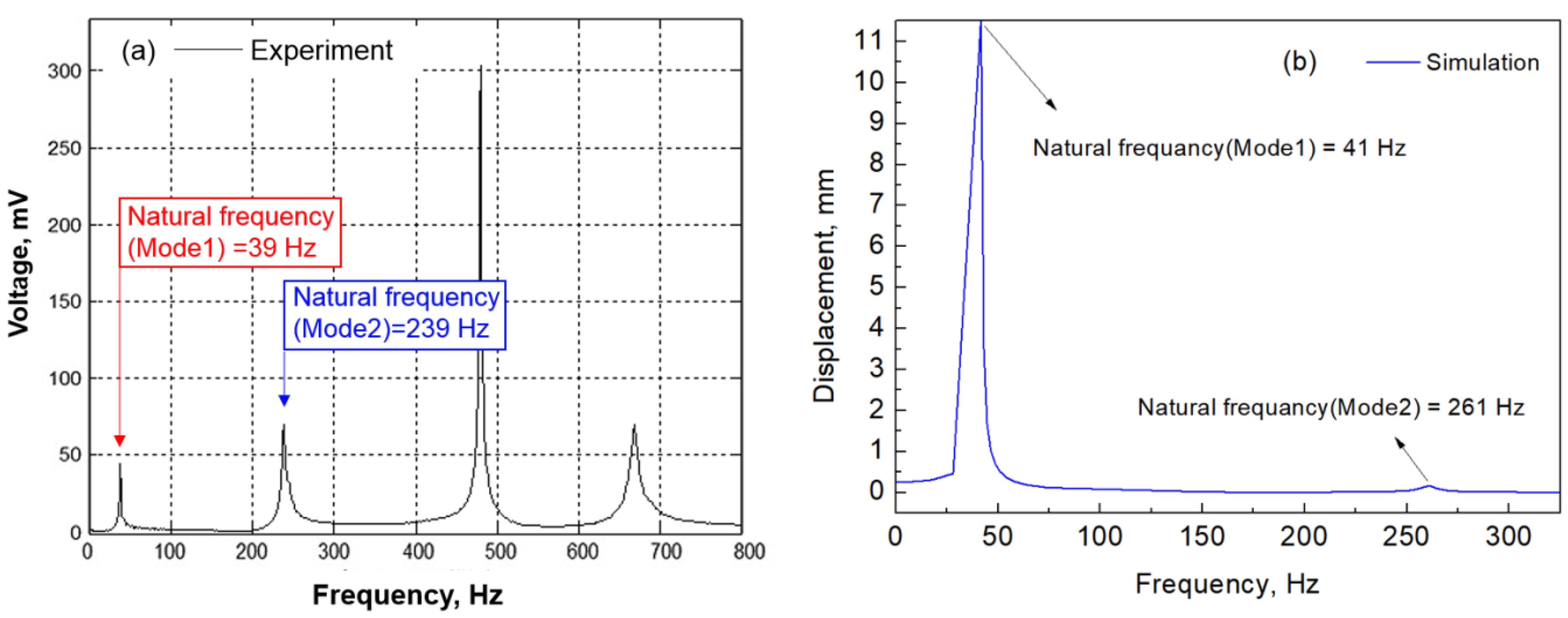
2.3. Impact Modal Tests

The structural damping ratio of Ti6Al4V specimens was obtained by impact modal tests. The impact modal tester consisted of a PCB-086B80 mini-hammer, a PCB-352C22 acceleration sensor and an oscilloscope. The impact modal tester and the fixtures of samples are shown in Figure 2. The damping properties were evaluated by structural damping ratio which can be obtained by the analysis of the frequency response results. Five samples were tested for each WLSP temperature and their average value was used to represent the structural damping ratio of the WLSPed samples at this temperature.

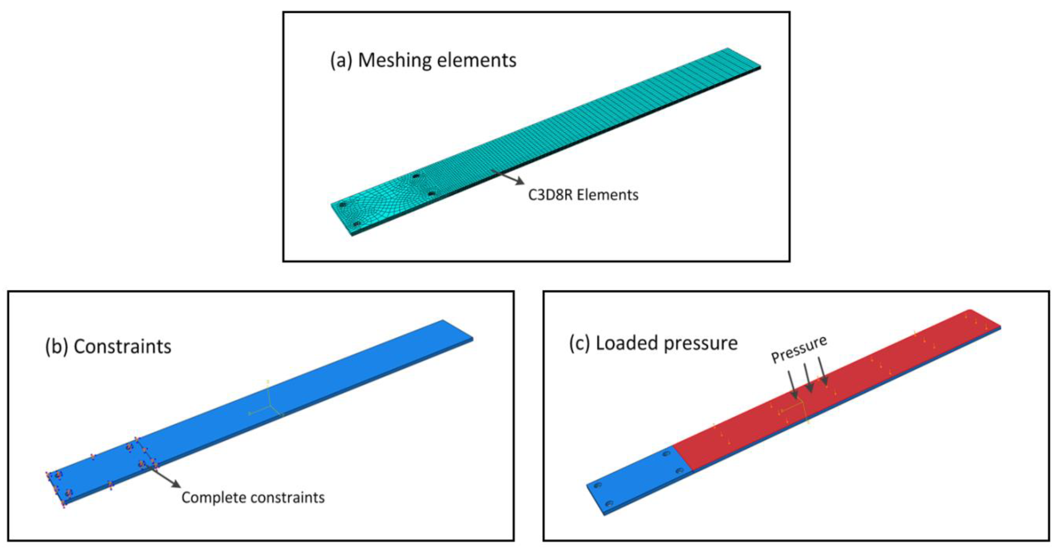
2.4. Frequency Response Simulations

Frequency response simulations can analyze the relationship between structural input (force, pressure, etc.) and output (displacement, stress, etc.) at different excitation frequencies. In order to obtain the influence of RT-LSP and WLSP on the maximum displacement and tensile stress of samples, the frequency response process of untreated, RT-LSPed and WLSPed specimens were simulated by ABAQUS software based on the structural damping ratios obtained in impact modal tests. According to the samples in Figure 1 and their fixtures in Figure 2, a finite element model with 63,752 elements was built, as shown in Figure 3a, and C3D8R elements were used in the model. The boundary of the finite element model was set to the solid boundary, and the material parameters used in simulation can be seen in Table 1. The stress and displacement were defined as output in the frequency response simulation. During the frequency response simulations, the side with four holes was fully fixed by complete constraints and the pressure was uniformly loaded on the surface of the other side, which is shown in Figure 3b,c. In addition, the pressure of 100 MPa, 200 MPa and 300 MPa was selected in the frequency response simulations. Frequency response curves of RT-LSPed samples obtained by the experiment and simulation are shown in Figure 4. It can be seen that the natural frequency obtained by the simulation has small differences with that obtained by the experiment, which confirms that the finite element model and material parameters in this study are reasonable.

2.5. Residual Stress Measurement

An X-ray tube with a chrome anode operated at 22 kV and 6 mA was utilized to measure the residual stress on the RT-LSPed and WLSPed surface. The X-ray beam diameter was 1 mm. The X-ray source was Cokα ray and the diffraction plane was a phase (114) plane in the stress calculation. The scanning angle of 2θ was from 161° to 154° with a step angle of 0.1 °/s and a present time (time per measurements) of 1.0 s. In order to decrease the errors, five points were chosen on the surface of a RT-LSPed or WLSPed sample to measure the residual stress, and their average value was chosen as the final result.

2.6. Vibration Fatigue Tests

The vibration fatigue life was tested by a high-frequency vibration system, the parameters of which are shown in Table 4. In the vibration fatigue experiment, the excitation force was controlled by the acceleration of the platform. During vibration tests, the accelerated speed of the vibration table was set as 98 m2/s. The vibration fatigue life of the structure was studied in the resonant state (the excitation frequency was near the natural frequency). Because the natural frequency of the structure generally decreases with the increasing loading time, this paper tested the structural natural frequency every 50,000 times, and then used it as the excitation frequency to continue the vibration experiment. Thus we can obtain the vibration fatigue life in resonance state. The excitation frequency of the vibration system was set based on the first-order natural frequency. After the specimens ruptured, the fractures were observed by SEM (Scanning Electron Microscope) to analyze the fatigue crack growth rate during vibration.

3. Results and Discussion

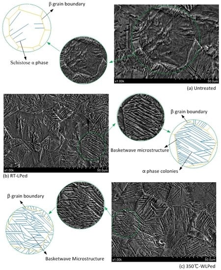
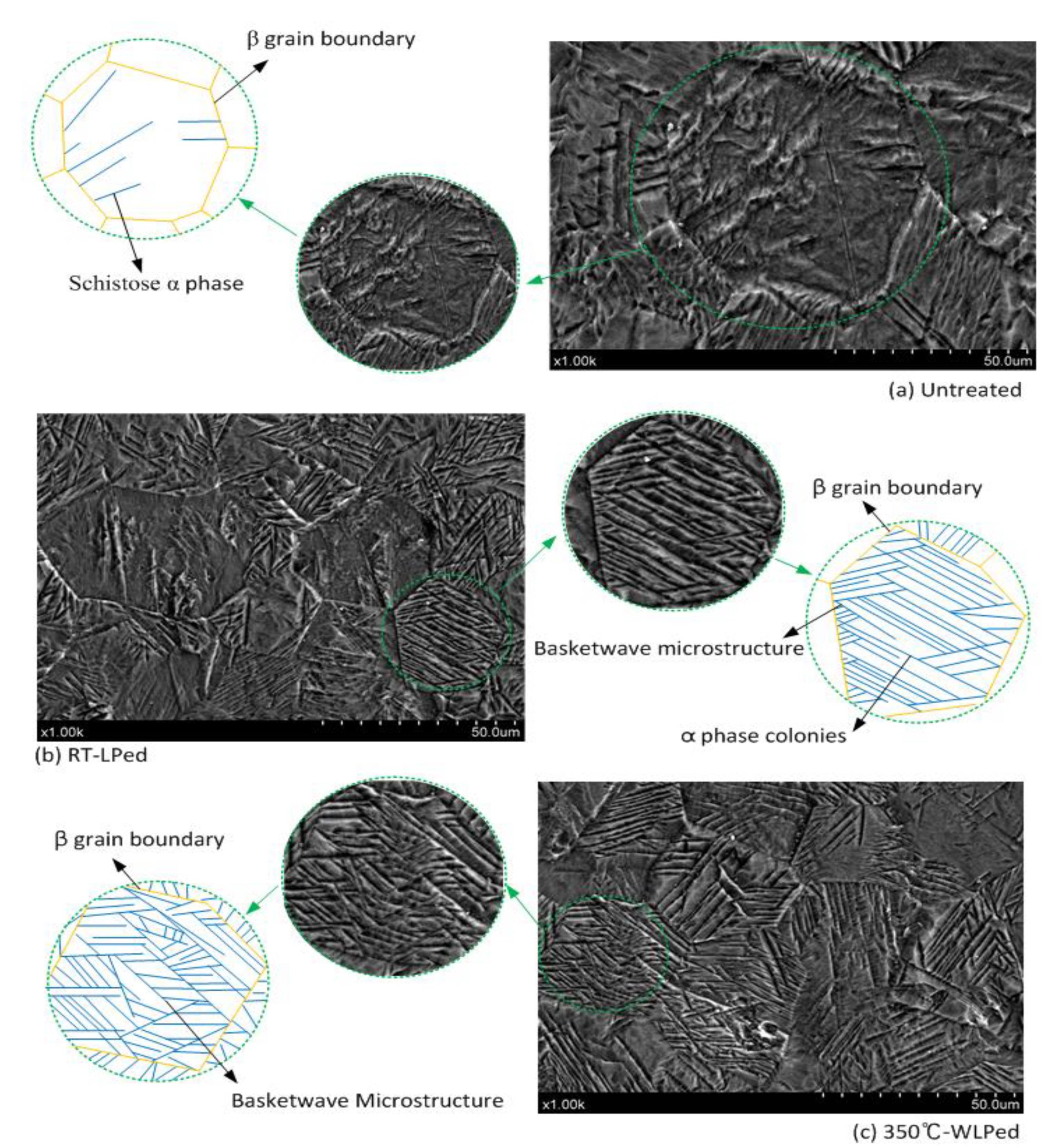
3.1. Microstructure in Ti6Al4V Titanium

The original microstructure of Ti6Al4V titanium alloy is shown in Figure 5a. It was found that the original microstructure was mainly composed of β grains with a little schistose α phase. Moreover, the β grains existed in the samples with a large average diameter and the schistose α phase mainly appeared around β grain boundaries, which led to a low volume fraction of interphase boundaries.
The microstructure on the surface of RT-LSPed samples is shown in Figure 5b. The results indicate that the plastic deformation with a high strain rate greatly decreased the average diameter of β grains, and the distribution of α phase in RT-LSPed samples was subjected to a significant change. It was found that the acicular α phase developed from β grain boundaries to the internal β grains, which was caused by the movement of grain boundaries and the break of schistose α phase. In β grains, the acicular α phase paralleled each other and thus many α phase colonies were formed. Moreover, the α phase colonies near β grain boundaries crossed each other and thus some basketweave microstructures appeared around β grain boundaries. Therefore, a mixed microstructure composed of α phase colonies and basketweave microstructures was generated by RT-LSP in Ti6Al4V titanium alloy.
The microstructure in 350 °C-WLSPed samples is shown in Figure 5c. It was observed that a large number of α colonies crossed each other inside the β grains, which greatly increased the volume fraction of basketweave microstructures and interphase boundaries. This was because the elevated temperatures during WLSP promoted the movement of grain boundaries and increased the plastic strain inside the β grains, which led to an increasing volume fraction of interphase boundaries.

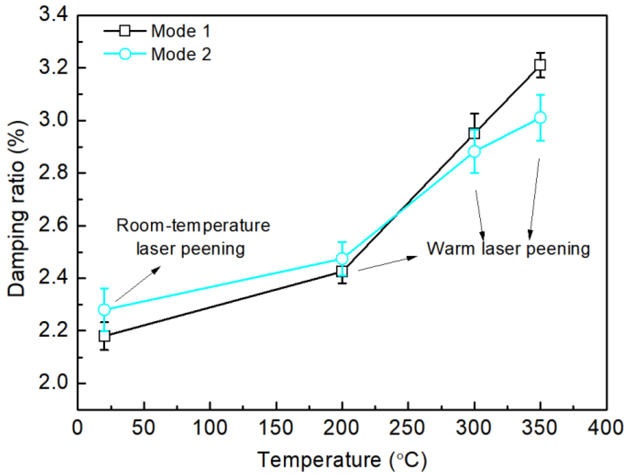
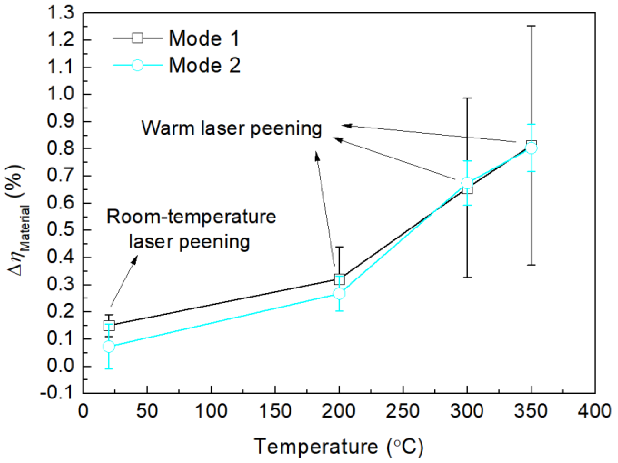
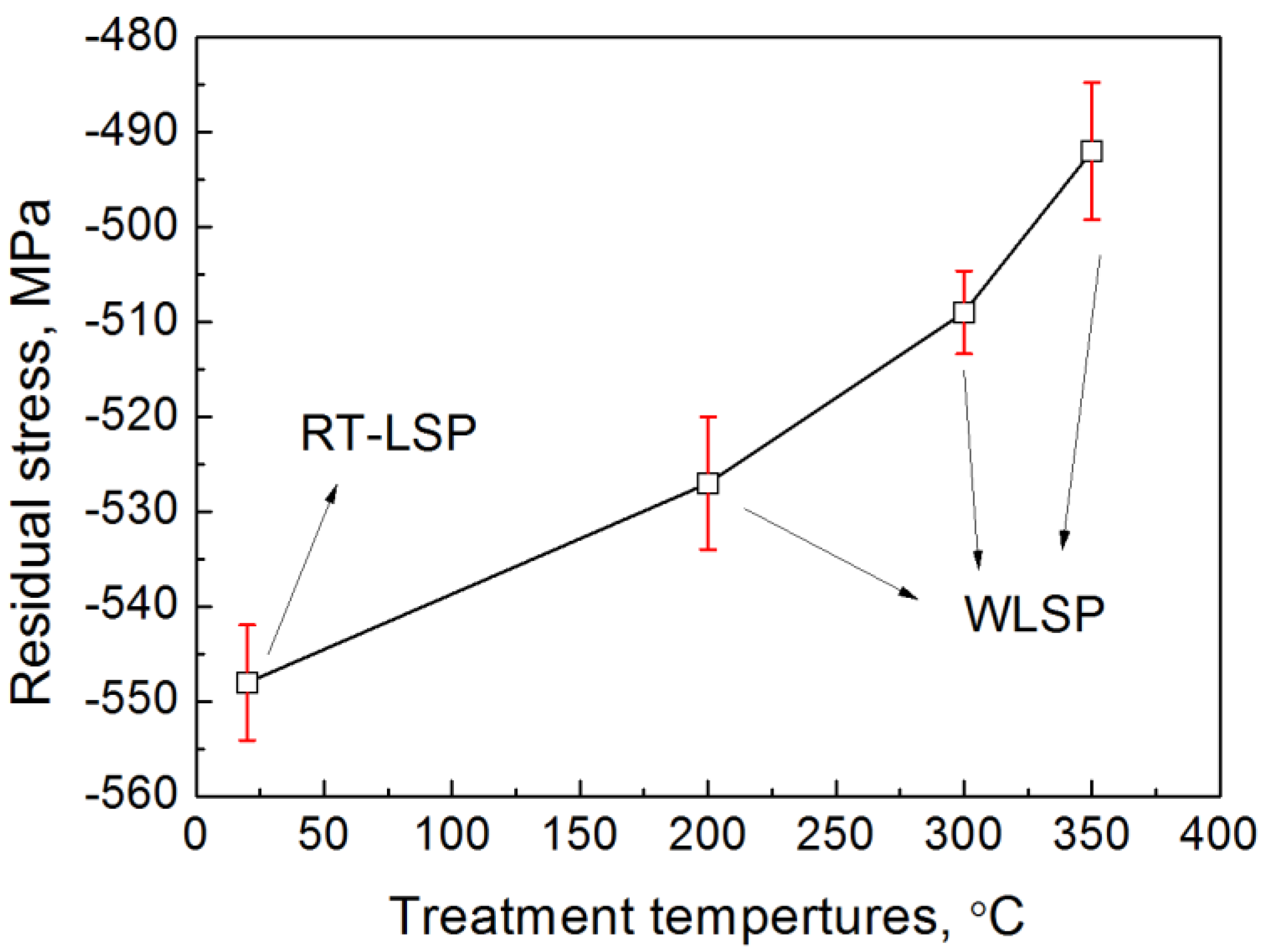
3.2. Damping Ratio and Residual Stress

The damping ratio of samples was mainly related to the decrease of energy during vibration. Therefore, the structural damping ratio η can be written as [19]:
η = Δ E 2 π U
where ΔE is the decrease of energy during vibration, U is the maximum potential energy during one vibration period. The units of ΔE and U are both joule (J).
The structural damping ratios of the samples treated by laser shock peening at different temperatures are shown in Figure 6. It was seen that the damping ratios of mode 1 and mode 2 both increased with the increasing treatment temperatures. The average structural damping ratios of mode 1 and mode 2 in 350 °C-WLSPed samples were 3.21% and 3.01%, which increased 47% and 32% compared with that in RT-LSPed samples.
Beside the internal friction in material, the decrease of energy-generated ΔE was also related to the samples’ dimensions, fixed method and some other factors. Therefore, the damping ratio of samples can be written as:
η = η material + η other
where ηmaterial is the material damping ratio generated by internal friction, ηother is the damping ratio induced by some other factors.
In this paper, except for the microstructure changes induced by RT-LSP and WLSP, the other experimental conditions have not changed. Thus, it can be concluded that:
η = η LSP + η untreat = η material - LSP η material - untreat = Δ η material
where Δη is the difference of structural damping ratio in LSPed and untreated samples, ηLSP and ηuntreat are the structural damping ratios of LSPed and untreated samples, Δηmaterial is the difference of material damping ratio in LSPed and untreated samples, ηmaterial-LSP and ηmaterial-untreat are the material damping ratios in LSPed and untreated samples.
Based on the structural damping ratio of the samples in Figure 6, the value of Δηmaterial as a function of treatment temperatures is shown in Figure 7. It was seen that the Δηmaterial of mode 1 and mode 2 both increased with the increasing treatment temperatures. The decrease of energy generated by internal friction was mainly decided by the movement and friction between the microstructures in materials, such as dislocations, grain boundaries and interphase boundaries [20]. In Ti6Al4V titanium alloy, there are a large number of α and β phases, as shown in Figure 5. Thus the internal friction between the phase boundaries was the most important part of the damping ratio of Ti6Al4V titanium alloy, and the damping ratio increased with the increasing interphase boundaries. Based on the microstructure in Figure 5, the increasing interphase boundaries generated by 350 °C-WLSP significantly increased the internal friction during vibration. Therefore, the damping ratio generated by internal friction in the 350 °C-WLSPed sample was much greater than that in RT-LSPed and untreated samples.
The residual stress on the surface of RT-LSPed samples and WLSPed samples is shown in Figure 8. It indicates that high compressive residual stress (CRS) is induced by RT-LSP and WLSP in Ti6Al4V titanium alloy. Moreover, the amplitude of CRS decreases with the increasing treatment temperatures. For example, the amplitude of CRS induced by 350 °C-WLSP (492 MPa) decreased about 10.2% compared with that induced by RT-LSP (548 MPa). The reason was that high temperature during WLSP resulted in a relaxation of CRS [21].

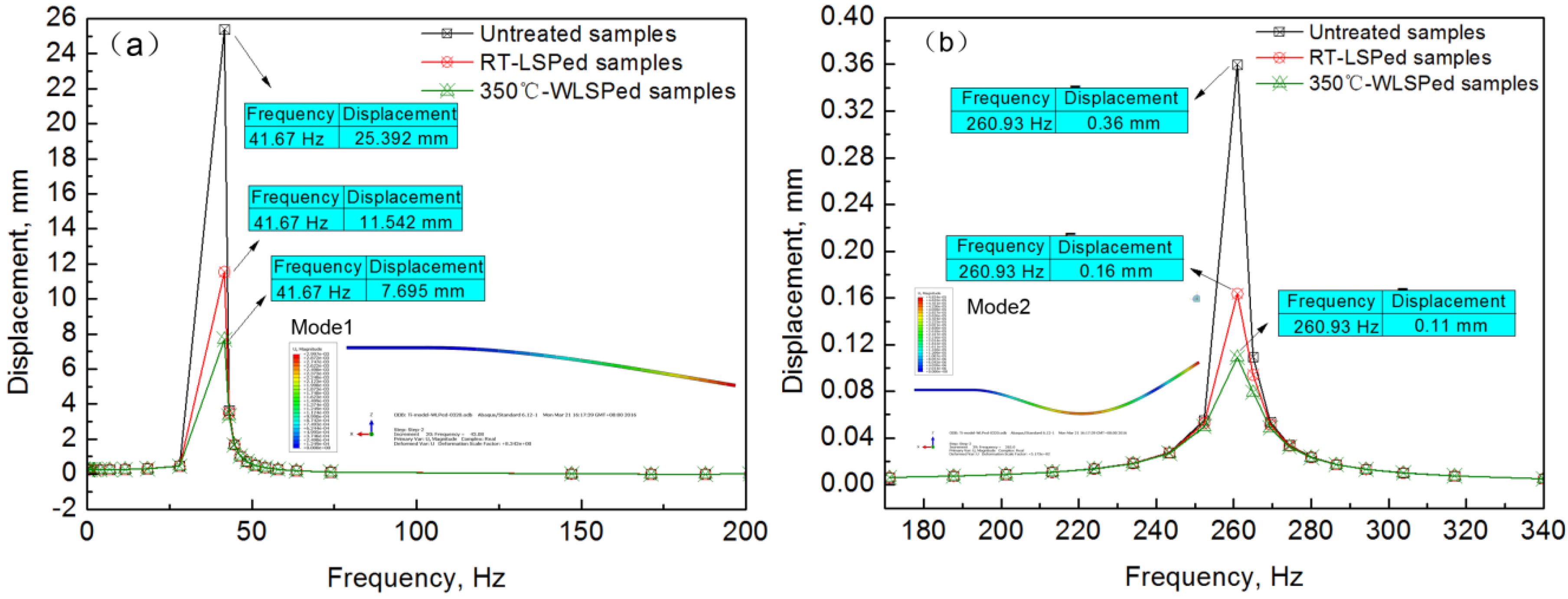
3.3. Vibration Displacement and Stress

The frequency response process of untreated, RT-LSPed and 350 °C-WLSPed samples are shown in Figure 9. It was found that the maximum displacement of RT-LSPed samples was about 11.542 mm and 0.16 mm at the natural frequency of mode 1 and mode 2, while it was only 7.695 mm and 0.11 mm in 350 °C-WLSPed samples. It can be concluded that the maximum displacement of 350 °C-WLSPed samples is much lower than untreated and RT-LSPed samples during vibration because of the increasing damping ratio. Based on Equation (1), the total input energy Et can be written as:
E t = Δ E + 2 π U = 2 π ( 1 + η ) U
In Equation (4), the maximum potential energy U can be written as:
U = 1 2 k X 2
where k is equivalent elastic coefficient, X is the maximum displacement during one vibration period. Thus, the total input energy Et can also be written as:
E t = π k ( 1 + η ) X 2
It can be concluded that the maximum displacement during one vibration period decreases with the increasing structural damping ratio when the total input energy is unchanged.
The vibration maximum displacement as a function of loaded pressure at the frequency of 43.08 Hz and 265 Hz is shown in Figure 10. It was found that the maximum displacement increased with the increasing loaded pressure and decreased with the increasing WLSP temperatures. The difference of maximum displacement between 350 °C-WLSPed samples and untreated samples increased with the increasing loaded pressure. For example, when the frequency was 43.08 Hz, the difference between 350 °C-WLSPed samples and untreated samples in the maximum displacement was about 0.61 mm under the pressure of 100 MPa, and it increased to 1.81 mm when the pressure increased to 300 MPa.
Based on the Equation (6), it can be obtained that:
{ E t = π k 0 ( 1 + η 0 ) X 0 2 E t = π k w ( 1 + η w ) X w 2
where k0 and kw are equivalent elastic coefficients of untreated samples and WLSPed samples, X0 and Xw are the maximum displacement of untreated samples and WLSPed samples, η0 and ηw are the structural damping ratio of untreated samples and WLSPed samples. If it is assumed that the total input energy Et is unchanged and k0 is equal to kw, it can be concluded from Equation (7) that:
{ | Δ X | = | X w X 0 | = ( 1 α ) X 0 α = 1 + η 0 1 + η w
where |ΔX| is the difference of maximum displacement between WLSPed samples and untreated samples. It can be found from Equation (8) that the difference of maximum displacement between WLSPed samples and untreated samples increases with the increasing X0. Because of the increasing X0 generated by the increasing loaded pressure, the difference of maximum displacement between 350 °C-WLSPed samples and untreated samples increases with the increasing loaded pressure.
The maximum vibration stress as a function of loaded pressure at the frequency of 43.08 Hz and 265 Hz is shown in Figure 11. The results indicate that vibration stress with high amplitude appears on the surface of the vibration samples. At the frequency of 43.08 Hz and 265 Hz, the maximum stresses both appeared near the fixed side of the samples. However, the maximum vibration stress obtained at the frequency of 43.08 Hz was much higher than that obtained at the frequency of 265 Hz, which indicates that the vibration at the frequency of mode 1 is much easier to result in fatigue failure.
It can also be seen in Figure 11 that the maximum vibration stress increases with the increasing loaded pressure. Moreover, the maximum vibration stress was greatly reduced by RT-LSP and 350 °C-WLSP compared with untreated samples. For example, when the vibration tests were conducted with a pressure of 300 MPa and a frequency of 43.08 Hz, the maximum vibration stress in untreated, RT-LSPed and 350 °C-WLSPed samples were 117.3 MPa, 108.6 MPa and 97.3 MPa, respectively. The maximum vibration stress in 350 °C-WLSPed samples was decreased by 17.1% compared with untreated samples. Besides, the difference of maximum vibration stress between 350 °C-WLSPed and untreated samples increased with the increasing loaded pressure.

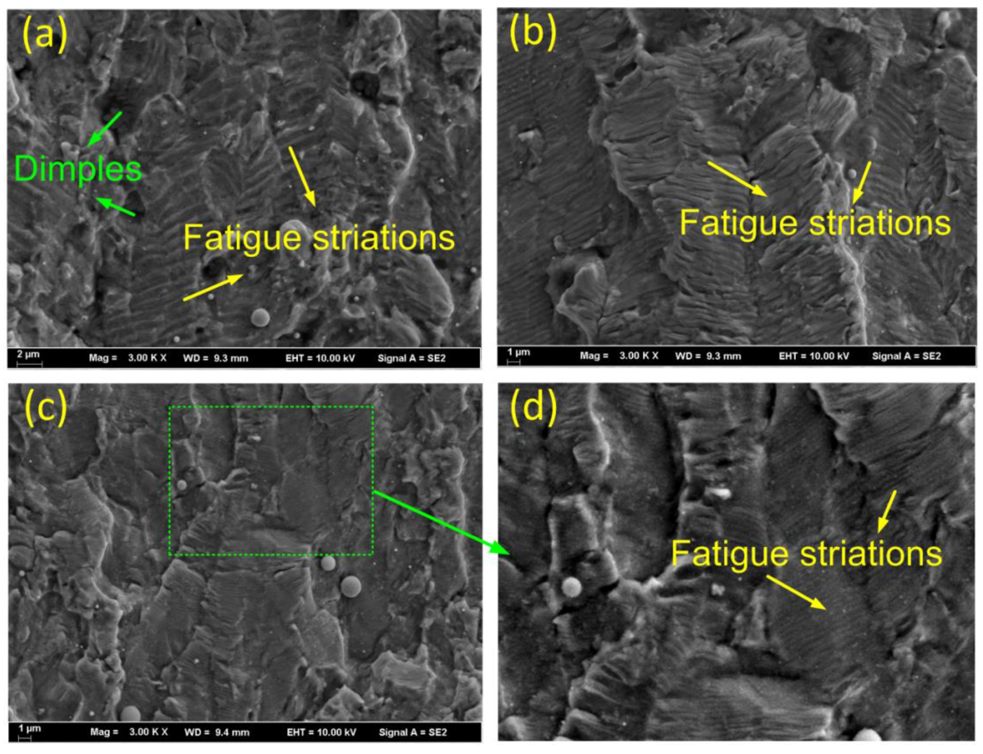
3.4. Vibration Fatigue Properties

The fracture morphologies of untreated, RT-LSPed and 350 °C-WLSPed Ti6Al4V titanium samples are shown in Figure 12, which were obtained in the crack growth zone of fatigue fracture cross-section in the subsurface layer (about 500 microns away from the top surface). It can be seen in Figure 12a that there were some small dimples and many fatigue striations in the fracture of untreated samples. The fatigue striations were generated by periodically varying loads and the spacing between fatigue striations can be used to characterize the fatigue crack growth rate [22]. Moreover, because of the high vibration stress, the stress at the crack tips of untreated samples was so high that local material was torn to produce dimples.
The fracture morphology of RT-LSPed samples is shown in Figure 12b. Owing to the decreasing vibration stress and high CRS induced by RT-LSP, the stress at the crack tips was significantly decreased that there were few dimples in fractures. In addition, the spacing between fatigue striations in RT-LSPed samples was much smaller than that in untreated samples, which indicates that the fatigue crack growth rate was greatly decreased by RT-LSP because of the high CRS and decreasing vibration stress.
The fracture morphology of 350 °C-WLSPed samples is shown in Figure 12c,d. It can be seen in Figure 12c that there were major fatigue striations in 350 °C-WLSPed samples, which was similar to RT-LSPed samples. Figure 12d shows a local magnification of Figure 12c. It indicates that the spacing between fatigue striations in 350 °C-WLSPed fractures was much smaller than that in RT-LSPed fractures, which indicates that the fatigue crack growth rate of 350 °C-WLSPed samples was much lower than RT-LSPed samples. Besides the CRS, high damping ratio induced by 350 °C-WLSP decreased the vibration stress during vibration tests which led to a much lower fatigue crack growth rate. Owing to the low fatigue crack growth rate, the vibration fatigue life of 350 °C-WLSPed samples was much more than that of untreated and RT-LSPed samples. After vibration fatigue testing, the average vibration fatigue life of untreated, RT-LSPed and 350 °C-WLSPed samples were 793,651, 1,360,310 and 1,973,811 cycles, respectively. The average vibration fatigue life of 350 °C-WLSPed samples increased about 45.1% compared to RT-LSPed samples.

4. Conclusions

In this paper, the damping properties of Ti6Al4V titanium alloy treated by laser shock peening at different treatment temperatures were investigated by the impact modal tests, which were explained by the microstructures in material. Moreover, the frequency response process was studied by finite element simulations and vibration fatigue properties were investigated and analyzed. The following conclusions can be drawn:
1. Because of the increasing movement of grainboundaries and the increasing plastic strain inside the β grains, there are more basketweave microstructures and interphase boundaries appearing in 350 °C-WLSPed samples than RT-LSPed and untreated samples.
2. Due to the increasing interphase boundaries, the internal friction in 350 °C-WLSPed samples is significantly increased and thus the material damping ratio of 350 °C-WLSPed samples is much greater than RT-LSPed and untreated samples. Therefore, the displacement and vibration stress during the frequency response process are both decreased by 350 °C-WLSP.
3. The spacing between fatigue striations in 350 °C-WLSPed fractures is much smaller than that in RT-LSPed fractures, which indicates a much lower fatigue crack growth rate. Therefore, the vibration fatigue life of 350 °C-WLSPed samples increases 45.1% compared to RT-LSPed samples.

Author Contributions

Conceptualization, X.M. and J.Z.; Methodology and Software, J.L.; Validation, X.M. and Y.Z.; Formal Analysis and Investigation, X.M. and S.H.; Writing—Original Draft Preparation, X.M. and Y.Z.; Writing—Review & Editing, J.Z. and C.S.

Funding

This research was funded by the Natural Science Foundation of Jiangsu Province (No. BK20180881), Jiangsu Key Laboratory of Green Process Equipment (No. GPE201803), China Postdoctoral Science Foundation Funded Project (No. 2018M630526), Jiangsu Province Postdoctoral Research Grant Project (2018K014C), Open fund for Jiangsu Key Laboratory of Advanced Manufacturing Technology (No.HGAMTL-1808).

Conflicts of Interest

The authors declare no conflict of interest.

References

  1. Jha, A.K.; Singh, S.K.; Kiranmayee, M.S.; Sreekumar, K. Failure analysis of titanium alloy (Ti6Al4V) fastener used in aerospace application. Eng. Fail. Anal. 2010, 17, 1457–1495. [Google Scholar] [CrossRef]
  2. Sugianto, A.; Narazaki, M.; Kogawara, M. Failure analysis and prevention of quench crack of eccentric holed disk by experimental study and computer simulation. Eng. Fail. Anal. 2009, 16, 70–84. [Google Scholar] [CrossRef]
  3. Lingamanaik, S.N.; Chen, B.K. Microstructural and thermo-mechanical analysis of quench cracking during the production of bainitic–martensitic railway wheels. Eng. Fail. Anal. 2014, 40, 25–32. [Google Scholar] [CrossRef]
  4. Zhou, W.F.; Ren, X.D.; Liu, F.F.; Ren, Y.P.; Li, L. Nanocrystallization in the duplex Ti-6Al-4V alloy processed by multiple laser shock peening. Metals 2016, 6, 297. [Google Scholar] [CrossRef]
  5. Zhang, X.C.; Zhang, Y.K.; Lu, J.Z. Improvement of fatigue life of Ti–6Al–4V alloy by laser shock peening. Mater. Sci. Eng. A 2010, 527, 3411–3415. [Google Scholar] [CrossRef]
  6. Rubio-González, C.; Felix-Martinez, C.; Gomez-Rosas, G. Effect of laser shock processing on fatigue crack growth of duplex stainless steel. Mater. Sci. Eng. A 2011, 528, 914–919. [Google Scholar] [CrossRef]
  7. Zhang, W.Q.; Lu, J.Z.; Luo, K.Y. Residual stress distribution and microstructure at a laser spot of AISI 304 stainless steel subjected to different laser shock peening impacts. Metals 2015, 6, 6. [Google Scholar]
  8. Qiao, H. Experimental investigation of laser peening on Ti17 titanium alloy for rotor blade applications. Appl. Surf. Sci. 2015, 351, 524–530. [Google Scholar]
  9. Kim, J.C.; Cheong, S.K.; Noguchi, H. Residual stress relaxation and low- and high-cycle fatigue behavior of shot-peened medium-carbon steel. Int. J. Fatigue 2013, 56, 114–122. [Google Scholar] [CrossRef]
  10. Dalaeia, K.; Karlssona, B.; Svensson, L.E. Stability of residual stresses created by shot peening of pearlitic steel and their influence on fatigue behaviour. Procedia Eng. 2010, 2, 613–622. [Google Scholar] [CrossRef] [Green Version]
  11. Basu, I.; Al-Samman, T. Deformation, Recrystallization and Grain Growth Behavior of Large-Strain Hot Rolled Binary Mg-1Dy Alloy// Magnesium Technology 2014; Springer International Publishing: New York, NY, USA, 2014. [Google Scholar]
  12. Zhou, J.Z.; Meng, X.K.; Huang, S.; Sheng, J.; Lu, J.Z.; Yang, Z.R.; Su, C. Effects of warm laser shock peening at elevated temperature on the low-cycle fatigue behavior of Ti6Al4V alloy. Mater. Sci. Eng. A 2015, 643, 86–95. [Google Scholar] [CrossRef]
  13. Chen, H.S.; Zhou, J.Z.; Sheng, J.; Meng, X.K.; Huang, X.; Xie, X.J. Effects of Warm laser shock peening on Thermal Stability and High Temperature Mechanical Properties of A356 Alloy. Metals 2016, 6, 126. [Google Scholar] [CrossRef]
  14. Liao, Y.L.; Ye, C.; Kim, B.J. Nucleation of highly dense nano-scale precipitates based on warm laser shock Peening. J. Appl. Phys. 2010, 108, 063518. [Google Scholar]
  15. Ye, C.; Sergey, S.; Kim, B.J. Fatigue performance improvement in AISI 4140 steel by dynamic strain aging and dynamic precipitation during warm laser shock peening. Acta Mater. 2011, 59, 1014–1025. [Google Scholar] [CrossRef]
  16. Vázquez Jiménez, C.A.; Gómez Rosas, G.; Rubio González, C. Effect of laser shock processing on fatigue life of 2205 duplex stainless steel notched specimens. Optics Laser Technol. 2017, 97, 308–315. [Google Scholar] [CrossRef]
  17. Meng, X.K.; Zhou, J.Z.; Su, C. Residual stress relaxation and its effects on the fatigue properties of Ti6Al4V alloy strengthened by warm laser shock peening. Mater. Sci. Eng. A 2016, 680, 297–304. [Google Scholar] [CrossRef]
  18. Nie, X.F.; He, W.; Zhou, L. Experiment investigation of laser shock peening on TC6 titanium alloy to improve high cycle fatigue performance. Mater. Sci. Eng. A 2014, 594, 161–167. [Google Scholar] [CrossRef]
  19. Zhang, L. Modal Analysis and Experiments; Tsinghua University Press: Beijing, China, 2011. [Google Scholar]
  20. Postnikov, V.S.; Pavlov, V.S.; Turkov, S.K. Internal friction in ferroelectrics due to interaction of domain boundaries and point defects. J. Phys. Chem. Solids 1970, 31, 1785–1791. [Google Scholar] [CrossRef]
  21. Zhou, Z.; Bhamare, S.; Ramakrishnan, G.; Mannava, S.R.; Langer, K.; Wen, Y.; Qian, D.; Vasudevan, V.K. Thermal relaxation of residual stress in laser shock peened Ti–6Al–4V alloy. Surf. Coat. Technol. 2012, 206, 4619–4627. [Google Scholar]
  22. Pant, B.K.; Pavan, A.H.V.; Prakash, R.V. Effect of laser shock peening and shot peening on fatigue striations during FCGR study of Ti6Al4V. Int. J. Fatigue 2016, 93, 38–50. [Google Scholar] [CrossRef]
Figure 1. Ti6Al4V specimens and WLSP processed area.
Metals 09 00746 g001
Figure 2. Equipment and specimens used in the impact modal tests.
Metals 09 00746 g002
Figure 3. Meshing elements, constraints and loaded pressure in frequency response simulations. (a) Meshing elements, (b) Constraints, (c) Loaded pressure.
Metals 09 00746 g003
Figure 4. Frequency response curve of RT-LSPed samples: (a) Experiment, (b) Simulation.
Metals 09 00746 g004
Figure 5. Microstructure in the surface of (a) Untreated, (b) RT-LSPed and (c) 350 °C-WLSPed samples.
Metals 09 00746 g005
Figure 6. Damping ratios of the samples treated by laser shock peening at different temperatures.
Metals 09 00746 g006
Figure 7. The value of Δηmaterial as a function of laser shock peening temperatures.
Metals 09 00746 g007
Figure 8. Residual stress on the surface of RT-LSPed and WLSPed samples.
Metals 09 00746 g008
Figure 9. Frequency response process of untreated, RT-LSPed and 350 °C-WLSPed samples when the loaded pressure is 300 MPa: (a) Mode 1, (b) Mode 2.
Metals 09 00746 g009
Figure 10. Vibration displacement as a function of loaded pressure. (a) Frequency = 43.08 Hz, (b) Frequency = 265 Hz.
Metals 09 00746 g010
Figure 11. Vibration stress as a function of loaded pressure. (a) Frequency = 43.08 Hz, (b) Frequency = 265 Hz.
Metals 09 00746 g011
Figure 12. Fracture morphology of Ti6Al4V titanium samples: (a) Untreated, (b) RT-LSPed (c) and (d) 350 °C-WLSPed.
Metals 09 00746 g012
Table 1. Typical mechanical properties of Ti6Al4V (TC4) titanium alloy.
MaterialYoung Modulus (GPa)Yield Stress (MPa)Ultimate Stress (MPa)Elongation at Fracture
Ti6Al4V titanium11082610509.6%
Table 2. Technical parameters of Nd:YAG laser.
ParametersValueParametersValue
Operation materialNd:YAGFrequency (Hz)1–5
Wavelength (nm)1064Power distributionFlat
Pulse power (J)<16Spot shapeCircle
Pulse width (ns)<12Focus size (mm)Φ3–8
BPP (mm·mrad)<20TEM mode00
Table 3. Processing parameters used in RT-LSP and WLSP.
Pulse Energy (J)Spot Diameter (mm)Export StabilityPulse Width (ns)Laser Wavelength (nm)Frequency (Hz)
93<5%1010641
Table 4. Technical parameters of vibration system.
ParametersValueParametersValue
Exciting frequency (Hz)5–4500Exciting force (N)2940
Maximum acceleration (m/s2)980Maximum peak-peak displacement (mm)40
Carrying capacity (kg)<120Maximum speed (m/s)2

