Article

Plasma Multiwire Technology with Alternating Wire Feed for Tailor-Made Material Properties in Wire and Arc Additive Manufacturing

Welding and Joining Institute, RWTH Aachen University, 52062 Aachen, Germany
*
Author to whom correspondence should be addressed.
Metals 2019, 9(7), 745; https://doi.org/10.3390/met9070745
Submission received: 30 April 2019 / Revised: 22 June 2019 / Accepted: 28 June 2019 / Published: 2 July 2019
(This article belongs to the Special Issue Arc-based Additive Manufacturing)

Abstract

:
Wire and arc additive manufacturing (WAAM) is one of the most promising technologies for large-scale 3D printing of metal parts. Besides the high deposition rates, one of the advantages of WAAM is the possibility of using in situ alloying to modify the chemical composition and therefore the material properties of the fabricated workpiece. This can be achieved by feeding multiple wires of different chemical compositions into the molten pool of the welding process and generating a new alloy during the manufacturing process itself. At present, the chemical composition is changed stepwise by keeping the wire feed speeds per layer constant. This article describes the possibilities of generating chemically graded structures by constantly alternating the wire feed speeds of a multiwire WAAM process. This enables the chemical composition to be smoothly changed during the printing process, and generating structures with highly complex material properties. Several material combinations for different possible applications were successfully tested. Furthermore, grading strategies to avoid negative influences of low-ductility intermetallic phases were examined. The results show that low-ductility phases may even have a beneficial influence on the fracture behavior if they are combined with ductile phases. Moreover, prospective possible applications are discussed.

1. Introduction

Functionally graded materials (FGM) are technically applied materials, characterized by a graded variation of the chemical composition and/or the microstructure and/or the material properties [1]. The use of functionally graded materials opens up a wide range of possible applications, and it is an area that has been characterized by continuous research and further development [2,3,4]. The aim here is to manufacture workpieces that are locally adapted to their loads, thus allowing a significantly more efficient operation. To achieve this adaption, material properties, such as tensile strength, damping properties, and chemical and/or thermal resistance, can be varied. One example of the advanced functionality gained by local variation of material properties is the manufacturing of self-sharpening cutting blades for harvesting applications [5]. A graded change of the material properties is supposed to avoid sharp transitions of the chemical and physical properties and prevent local stress peaks. Based on the capabilities of the manufacturing process, FGMs can be produced with a gradually graded or continuously graded change of the materials. Initially, investigations mainly focused on the processing of metal-to-ceramic FGMs. Here, a huge variety of manufacturing processes was investigated for the processing of FGMs, such as sintering or plasma spraying [6].
With advances in metal additive manufacturing (AM), especially in laser-powder-based processes, a variety of investigations on metal-to-metal FGMs have started [6]. Possible material combinations range from differently alloyed steels, titanium to titanium carbides, iron to iron aluminides, and iron or copper base alloys to nickel base alloys [6,7]. The formation of intermetallic phases, especially when processing metal-to-metal FGMs, may lead to a sudden change in material properties that opposes the effect of a soft gradient. Zhang et al. used hardness profiles as an indicator for the structural properties of a Ti–TiC FGM [8].
Three-dimensional (3D) printing processes are suitable for the production of functionally graded workpieces as they allow highly individualized workpiece production [9]. Additive manufacturing processes for metallic structures can be divided based on the material feed into powder bed, powder feed (jet), and wire feed systems [10]. Using powder as the initial feed material is relatively expensive compared to wire, which is why powder-based processes are typically used for the processing of expensive materials and the production of small-sized, high-precision workpieces [11]. The basic challenges in additive manufacturing of metals are independent of the process. Due to the high heat input of the energy source, the material of the last deposited layer undergoes a heat treatment. This may lead to anisotropic material behavior [10]. Moreover, thermally induced residual stresses and common welding-related defects, such as lack of fusion or porosity, may occur [10,12]. The combination of an electric arc as heat source and wire as feeding material for processing metallic FGMs has, for a long time, not been the main focus of research.
Wire and arc additive manufacturing (WAAM) processes represent a key technology for economic series production of 3D-printed parts and are becoming increasingly important, both in research and in industrial applications [13,14]. Here, welding processes, such as gas metal arc (GMA), tungsten inert gas (TIG), or submerged arc (SA) welding, are used to build up structures by multilayer welding [14,15]. The key difference between WAAM and more commonly used additive manufacturing processes, such as laser powder bed fusion or laser cladding, lies in the high local heat input in combination with a high material deposition rate. Workpieces with a structural weight of more than 200 tons have been manufactured using WAAM [15,16]. Additionally WAAM is only used for processing metallic materials. Besides the high thermally induced residual stresses, one of the constraints of WAAM is the complex path planning and control process. Any alignment error of the welding torch leads to an increased risk of geometric inaccuracies and weld defects. To solve this problem, various research groups are working on automatic path planning and control systems, such as Chen et al. with their DingzhiPNT-3d Path simulation software in combination with a cold metal transfer (CMT), which is a gas metal arc welding (GMAW) process [17,18,19].
For additive manufacturing of high-performance materials like titanium or nickel base alloys, processes with nonconsumable electrodes, such as tungsten inert gas or plasma-transferred arc (PTA) welding, are used. In this context, the work carried out at Cranfield University in recent years should be mentioned as being fundamental for the development of such processes for additive manufacturing [20,21]. Industrial applications can be found, for example, at Norsk Titanium [22]. Here, titanium parts for the aerospace industry are additively manufactured with a modified plasma welding process in near-net-shaped condition and then machined to the final geometry. Compared to the machining of a simple semifinished product, this results in significant material savings and a more favorable buy-to-fly ratio. Further industrial examples for the use of WAAM in future applications are the manufacture of Pelton turbine blades [23], the contract manufacture of cost-reduced milled parts [24] as well as the manufacture of ship propellers [25] or heavy-duty crane hooks [26].
Arc welding processes also offer the possibility of generating multi-material components. Work at the TU Ilmenau is concerned with the additive production of composite workpieces using GMA welding. Here, in the sense of classical shape welding, hard material layers are applied specifically to a base material made of high-alloy steel in order to produce workpieces with locally adapted technical properties [27]. The material can be changed by exchanging the filler wire or by using a second welding torch. Using only one filler wire at the same time, this concept leads to multimaterial workpieces with sharp material transitions.
Welding processes with nonconsumable electrodes have the advantage of generating a very stable and well-defined molten pool and are therefore suitable for in situ alloying. In this application, the simultaneous feeding of multiple wires of different chemical compositions into the molten pool is applied in order to generate the new alloy in situ. The variety of investigated materials ranges from the production of titanium and iron aluminides to the processing of special nickel–aluminum bronze alloys [28,29,30,31,32]. Different approaches of changing the chemical composition layerwise to generate gradually graded structures have already been published [33]. The work of Brentrup et al. should especially be mentioned at this place [34]. Here, a GTA process in combination with a double-wire feeding system was used to produce graded ferrite-to-austenite FGMs. Furthermore, recent work carried out by the Chair of Welding Engineering, Chemnitz University, investigated the wire and arc additive manufacturing of FGMs. Here, FGMs were produced between SS316L steel and alloy626 nickel-based alloy using the plasma process [35]. As with the other abovementioned approaches, the chemical composition was changed in layers, which means that the wire feed speed was kept constant during the welding process. A consistent further development of this approach has resulted from the local variation of the individual wire feeding speeds in the process. This is aimed at producing workpieces with smoothly varying chemical composition, thus generating locally changing mechanical properties. This gives the possibility to change the chemical composition of the material within the printing layer and therefore opens new design freedom to change the material properties at any location in the printing volume. This article presents a new approach of dynamically changing the wire feed speed within the framework of the printing process, thereby generating FGMs that show a changed chemical composition within the printing layers.

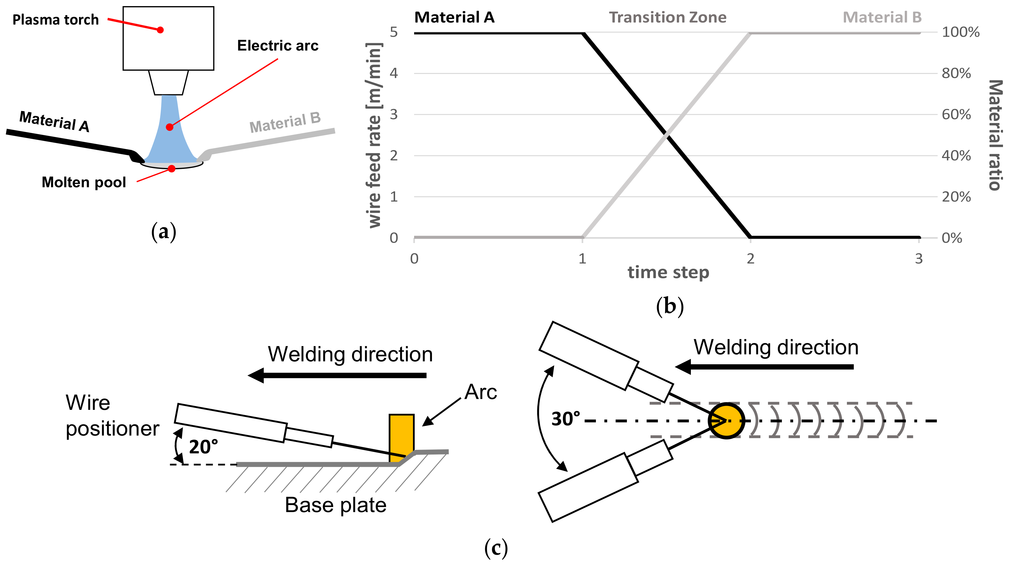
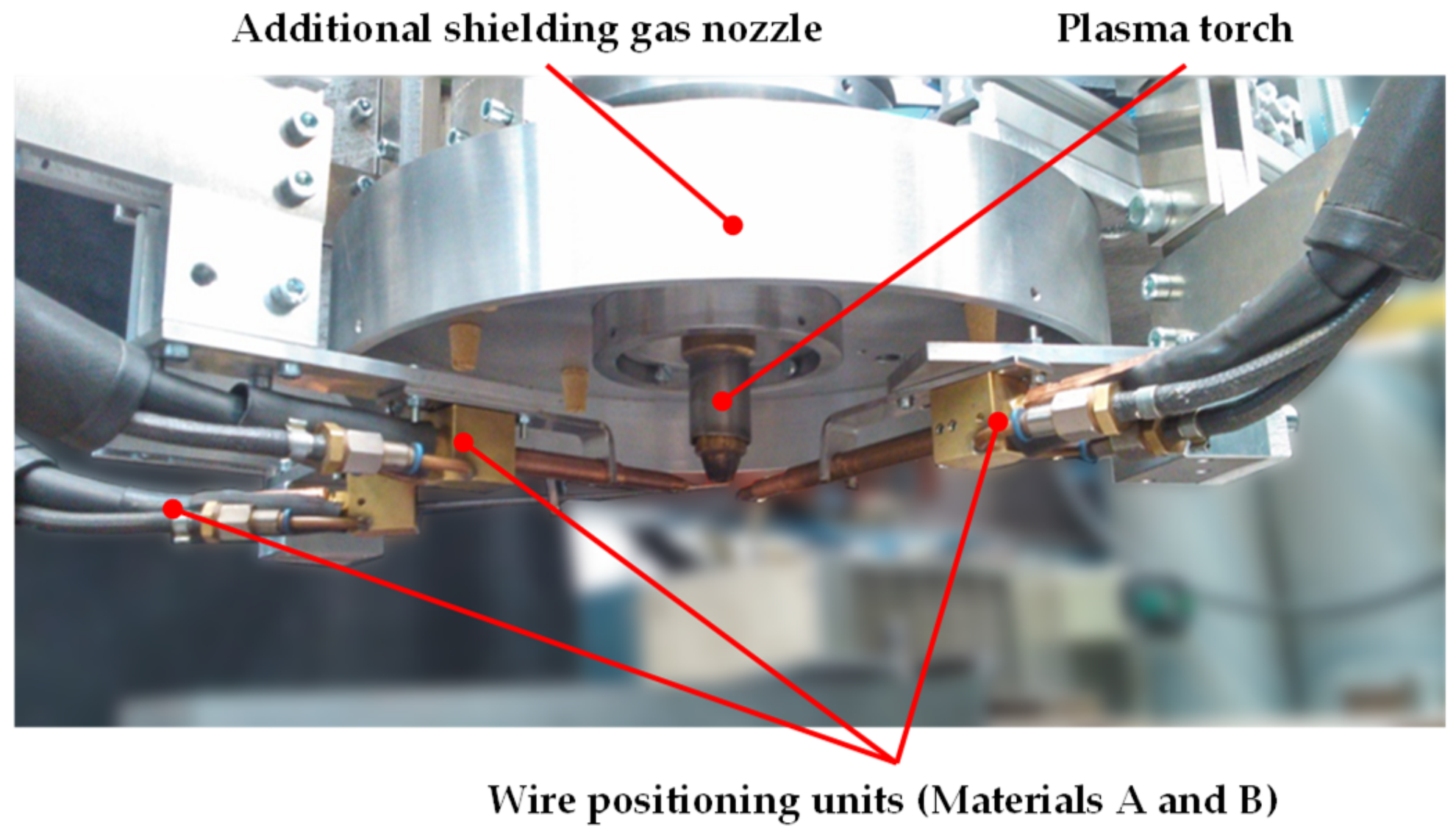
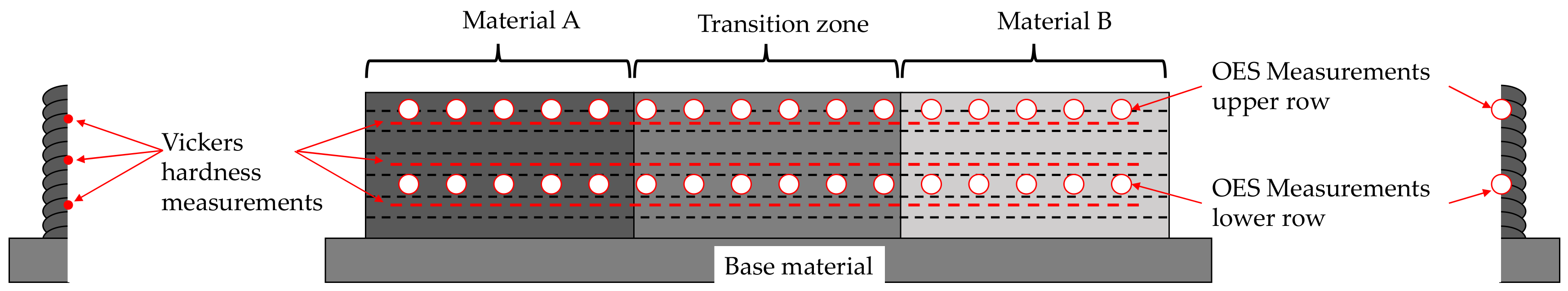
2. Materials and Methods

Three different material combinations were successfully processed. Table 1 shows the initial chemical composition of the processed wires before welding. As the loss of alloying elements can be expected when oxidizing shielding gases are used for welding, the manufacturers’ data sheets expect slightly different chemical compositions. The biggest difference between the measured value and the manufacturers’ datasheet applies to the niobium content in G 18 L Nb. After processing the wire with an M21 (EN ISO 14175) shielding gas, the expected content in the weld seam is 0.45%. All wires were of the dimension 1.0 mm. The material combinations were chosen in order to represent different technical applications and to evaluate the basic process capabilities and limitations for creating continuously graded FGMs, as shown in Table 2.
The aim of the experiments was to obtain a basic understanding of the process behavior and the possibilities as well as the restrictions when processing different materials to generate chemically graded structures. For the evaluation of the basic process stability of the plasma multiwire process, a combination of low-alloyed steel (EN ISO 14341-A: G 3Si1) and high-alloyed chromium–nickel steel (EN ISO 14343-A: G 19 9 LSi) was used. Initial results have been published in [36]. Due to the difference in thermal conductivity, the flow behavior of the liquid molten pool, and the solidification behavior, this material combination is supposed to reveal possible restrictions of the plasma multiwire process. Based on the results of this material combination, technically more relevant material combinations regarding two use cases were tested. The first use case dealt with chemically graded tube segments between ferritic steel and austenitic steel. Fusion welding of ferritic and austenitic materials can come into play when the structures underlie locally changing thermal loads, for example, in thermal power plants. In the low-temperature section, the nickel content was kept low to save costs. In the high-temperature section, the nickel content was increased to withstand the thermal loads. Chemically graded tube segments were used as transition elements to avoid welding of dissimilar metal joints. In this application, a smooth change of the chemical composition and the thermal expansion coefficient might lead to a higher resistance to thermally induced stresses. For this use case, the material combination of a high-alloyed ferritic chromium steel (EN ISO 14343-A: G 18 L Nb) to high-alloyed chromium–nickel steel (EN ISO 14343-A: G 19 9 L Si) was investigated.
The second use case involved structures of variable tensile strength. This might be interesting for architectural applications and steel construction, with WAAM for large-scale structures currently being investigated [37,38,39]. The possibility to change the tensile strength where geometric restrictions require a reduction of the load-bearing cross section may lead to greater freedom of design in the construction process. Therefore, a gradient from a low-alloyed steel (EN ISO 14341-A: G 3Si1) to a medium-alloyed high-strength steel (EN ISO 16834-A: G Mn4Ni2CrMo) was tested. All welding wires used were intended for use as GMAW electrodes.
To estimate the microstructure as well as possible weldability restrictions of the chemically graded structures, the positions of the new alloys were entered into the Schaeffler diagram, as shown in Figure 1.
All the work presented here was carried out using the plasma multiwire process, which is based on a common plasma (PTA) welding process. An electric arc burnt between a nonconsumable tungsten electrode and the workpiece, as shown in Figure 2a. Multiple wires of different chemical compositions were fed into the molten pool and built the final alloy in situ. The wire feed speed was changed during the running process, while the combined total wire feed speed was always kept constant, as shown in Figure 2b. At the start of the process, only material A was fed into the molten pool (time steps 0 to 1). During the transition time, the feed rate of material A was reduced, while the feed rate of material B was equally increased (time steps 1 to 2). In the last part of the weldment, only material B was fed into the molten pool (time steps 2 to 3). The wires were aligned with an angle of 20° relative to the workpiece surface and 30° between one another, symmetrical to the vector of the welding direction, as shown in Figure 2c. With the welding arc turned off, the wire tips just touched the workpiece surface below the plasma nozzle.
Regarding the welding equipment, a common plasma torch was used in combination with a wire feeding system. As wire feeding units, modified TIG welding power sources were applied. In order to achieve repeatable results as well as good shielding from atmospheric oxygen, different wire positioning units were constructed and tested. As the standard shielding gas nozzle of the plasma welding torch is not suitable for additive manufacturing, a combined wire positioning shielding gas unit was used to reduce the oxygen level around the welding area, as shown in Figure 3.
The wire feed units were controlled via computer-based measurement and control system. A labview program was written and allowed for repeatable wire feeding scenarios. The experiments presented in this article were carried out by generating wall-shaped structures with a chemical gradient from material A to material B along the longitudinal axis. The samples were divided into three characteristic zones: pure material A; transition area, which consisted of a linear change from material A to material B; and the zone of pure material B. Depending on the investigated material combination, different analysis methods were used. For investigating the macro- and microstructure of the samples, cross sections were analyzed. Investigations on the surface structure were done using a confocal laser scanning microscope. The chemical analysis of the samples was carried out using spark optical emission spectrometry (OES, SPECTRO Analytical Instruments GmbH, Kleve, Germany) and energy-dispersive X-ray spectroscopy (EDX, Bruker Corporation, Billerica, MA, USA). In order to characterize the strength distribution within the deposited structures, the hardness of the microstructure was determined using Vickers microhardness tests, as shown in Figure 4. In order to execute the hardness tests, wall-shaped structures with the effective dimensions 150 mm × 15 mm × 15 mm were produced, and longitudinal sections were prepared thereof along the centre line. The tensile strength was determined in parts with test specimens of the type DIN 50125–E2×6×20. The testing procedure was DIN EN ISO 6892-1, with 5 mm/min testing speed.
Based on the material combinations, different process gases were used. The optimization of the process parameters was carried out with the focus on process stability and low geometric errors of the weld beads. Table 3 gives an overview of the welding parameters used. The summarized wire feed speed was always kept constant, equal to the maximum wire feed speed. The current was reduced stepwise by 5 A per layer to compensate for the changing heat dissipation properties of the wall-shaped structures and to keep the geometric shape of the weld beads constant. In addition to the parameters shown in Table 3, experiments with changed process gases were carried out. Material combination 2 was also tested with I1-Ar as plasma gas and N2-ArN-2,5 (EN ISO 14175) as shielding gas to reduce the heat input and to increase the austenite range, leading to a finer grain structure. For initial tests, material combination 3 was welded using I1-Ar as shielding gas with the intention to investigate the possible loss of alloying elements. The interlayer temperature was measured with a contact thermometer (based on a type K thermocouple) on top of the last deposited weld seam. As soon as the temperature dropped below the limit value, the next weldment was started.

3. Results

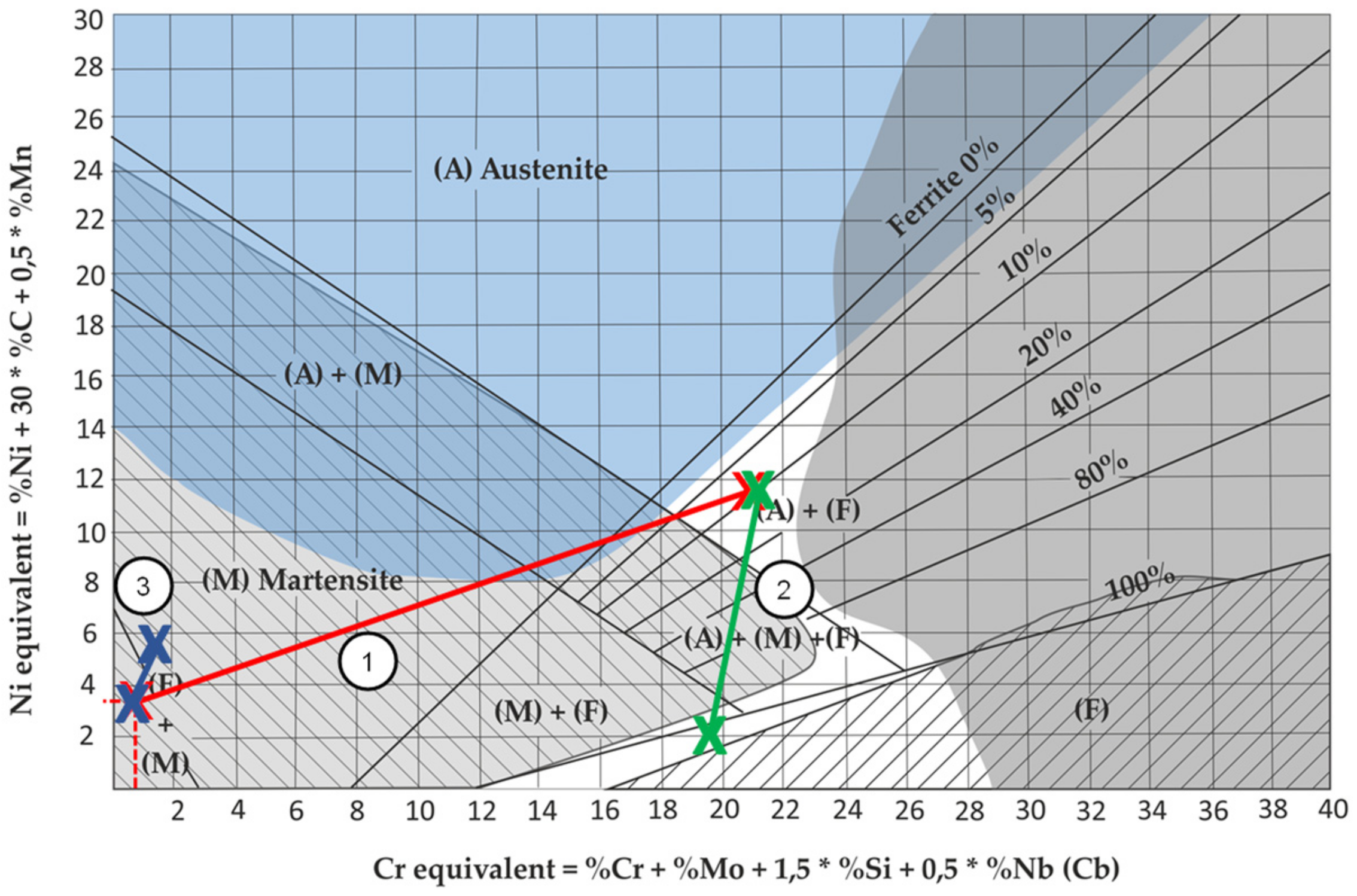
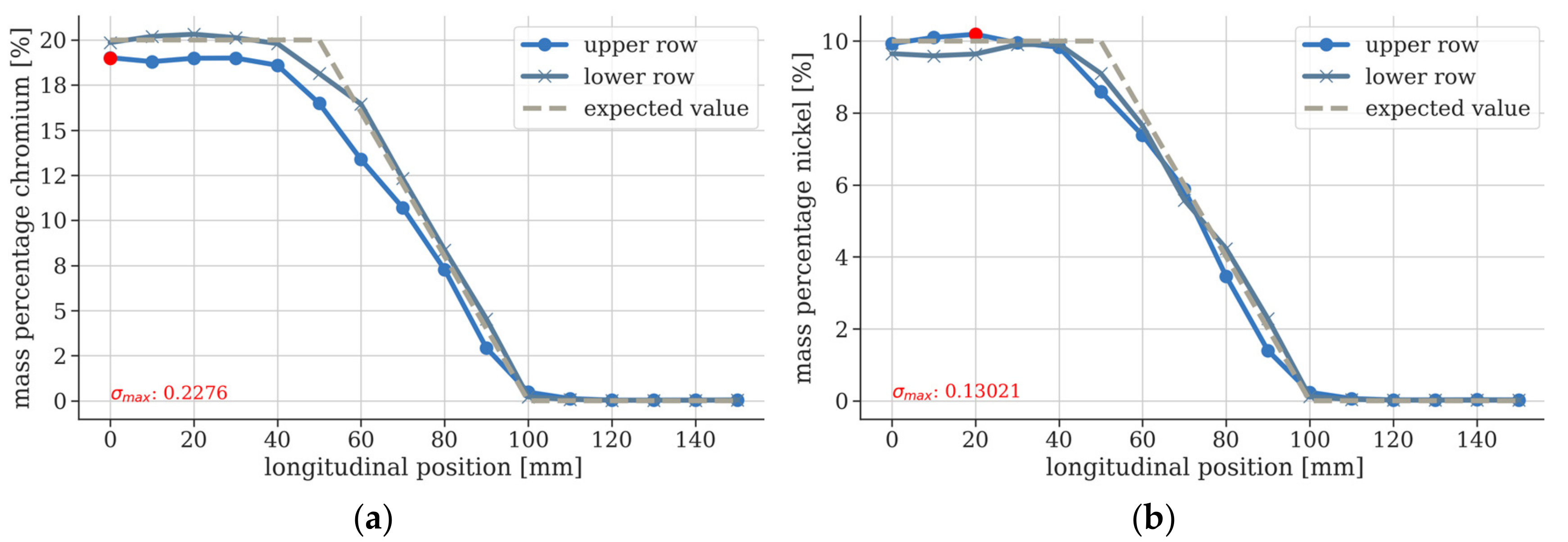
3.1. Material Combination 1: G 19 9 LSi to G 3Si1

The initial test welds revealed a low geometric error along the three material zones. Wall-shaped, chemically graded structures were manufactured in multilayer as well as single-layer configuration without excessive geometric irregularities in the transition area. OES measurements showed that the desired chemical composition of the in situ alloy could be set very precisely in terms of the characteristic elements chromium and nickel, as shown in Figure 5. The expected value, shown in the OES diagrams, is based on the manufacturers’ specifications for the chemical composition of all-weld metal samples, including the expected loss of alloying elements by passing the electric arc.
On closer inspection of the microscopic area, however, the material combination showed minimal inhomogeneities in the distribution of the alloying elements in the transition area. The EDX analysis showed a periodical segregation of nickel and chromium per weld seam, as shown in Figure 6. Here, an increase in the chromium and nickel content can be seen along the vertical axis of the weld seam. This effect only occurred in local areas of the transition zone and has already been described in [22].
Hardness measurements showed an increase in the Vickers hardness all along the transition area, as shown in Figure 7. Parts of the transition area exceeded a hardness value of 400 HV1. The outliers located at positions 81, 86, and 112 mm could be explained by hidden microporosity below the prepared surface. Depending on the welding parameters and the shape of the produced samples, cold cracks occurred directly after welding. This effect was mainly observed when larger samples were manufactured and the heat input was increased.

3.2. Material Combination 2: G 18 L Nb to G 19 9 L Si

Based on the results of material combination 1, investigations followed on the material combination for the first use case. In order to determine the quality of the gradation, the chemical composition over the specimen length as well as Vickers hardness were determined. Wall-shaped structures were welded onto substrate plates of structural steel as well as high-alloyed chromium–nickel steel. Welding on substrate plates of structural steel was possible; however, on larger build-up heights, hardness cracks occurred between the lowest weld seam and the substrate plate. The main alloying elements that were changed along the welding direction were nickel and niobium. Similar to the first material combination, the OES analysis showed a linear change of the nickel content in the transition area, as shown in Figure 8.
The investigations showed that the resulting chemical composition could be precisely adjusted by changing the wire feed speed. Furthermore, an influence of mixing with the base plate within the first layers could be detected, which explains the slightly reduced content of nickel within the lower measuring line. Changes in Ni content inside the weld seams were not substantiated by the EDX analysis. Hardness measurements followed the longitudinal direction, as shown in Figure 9.
The hardness gradients showed an increase of hardness in the transition area. The hardening correlated with the prediction of a martensitic microstructure using the Schaeffler diagram. Although the transition zone showed an increase of hardness, it was much lower compared to the first material combination.
Figure 10 shows cross sections of a wall-shaped structure. The pure chromium steel showed a high amount of coarse grains, while the grains got finer with rising nickel content.
The grain size of the chromium steel could be influenced by adding nitrogen to the shielding gas, reducing the heat input and feeding small amounts of G 19 9 L Si from the beginning.

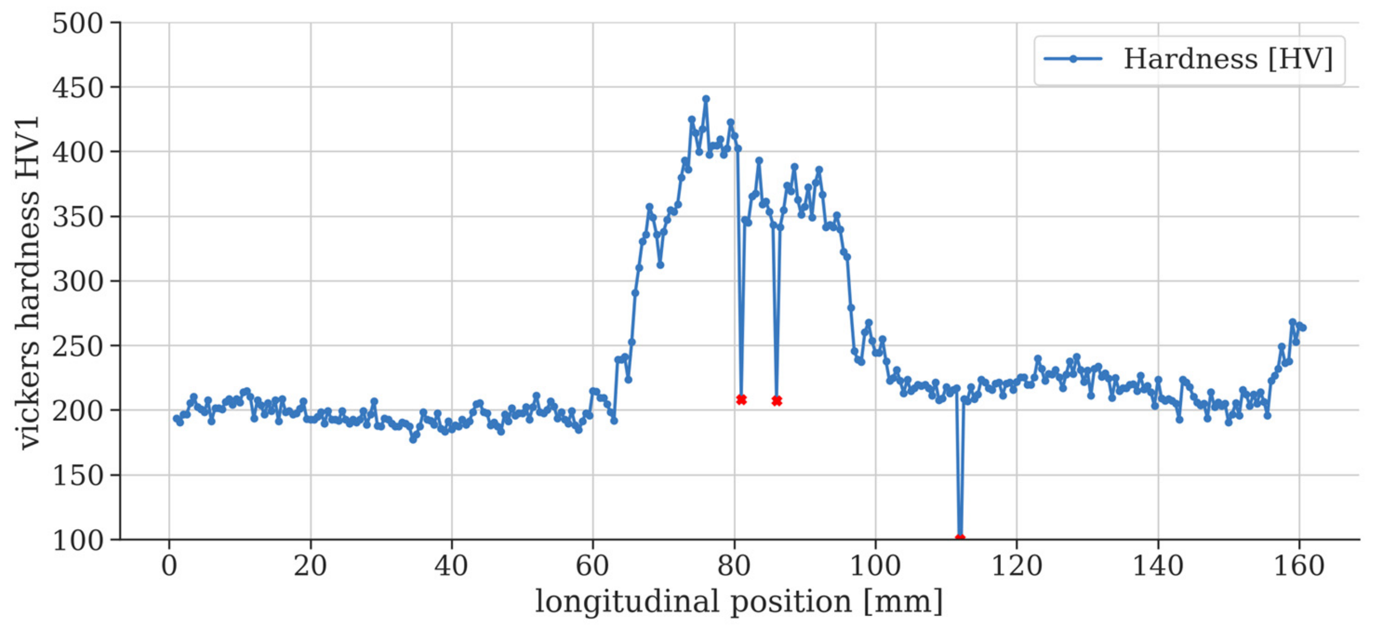
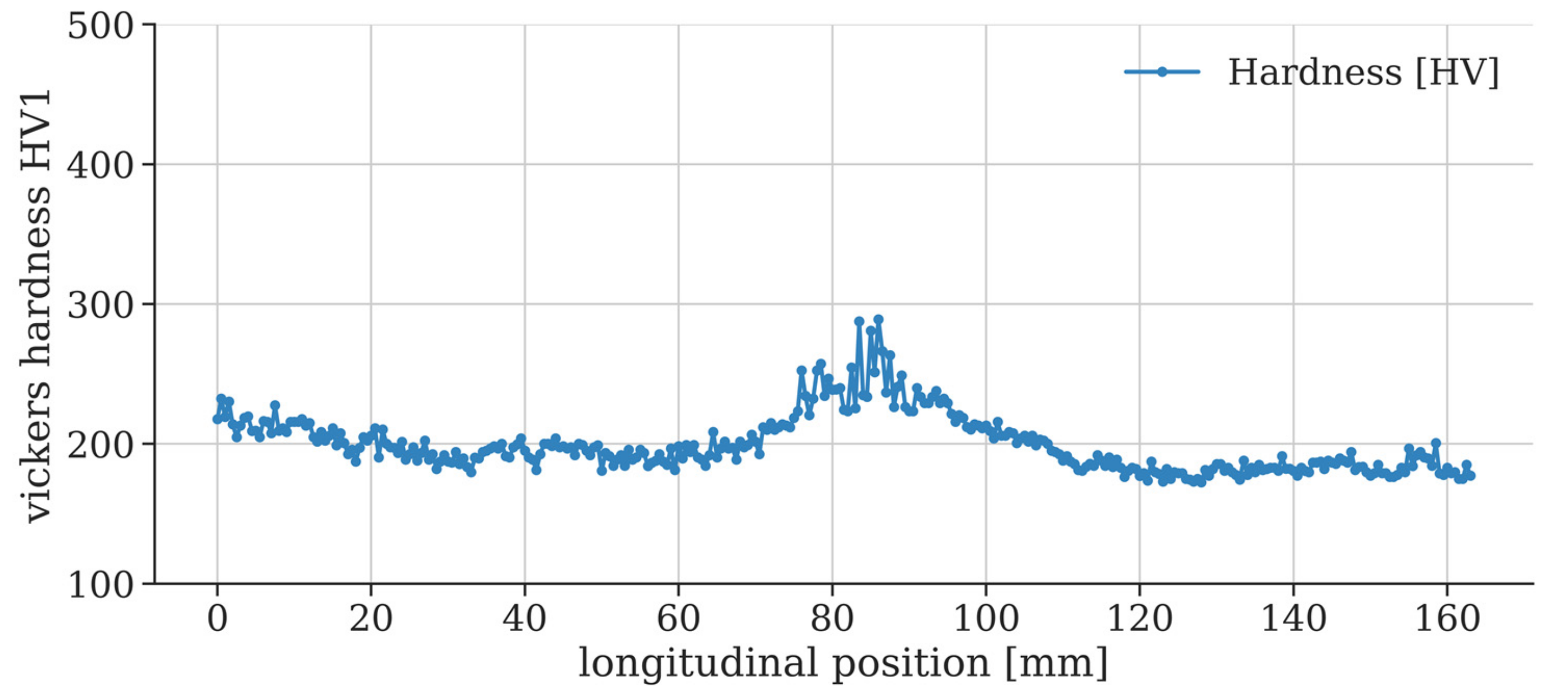
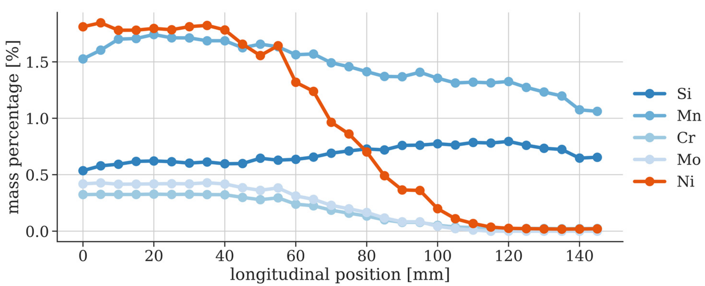
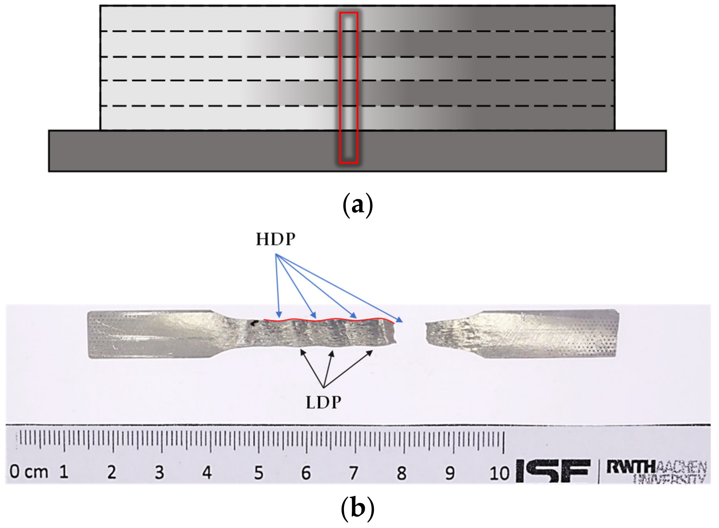
3.3. Material Combination 3: G Mn4Ni2CrMo to G 3Si1

For the second use case, welding experiments were carried out using a welding wire G 3Si1 in combination with a wire of the type G Mn4Ni2CrMo. As before, chemical composition and hardness were determined along the longitudinal axis of the wall-shaped structures.
The welding process showed a high stability and a high geometric accuracy of the weld seam. The starting and ending areas of the welded structures contained a low amount of porosity within the first 15 mm. Depending on the welding strategy, this effect could be suppressed. The results of the OES analysis showed a good accuracy regarding the content of the main alloying elements, as shown in Figure 11. In the starting and ending zones, a slight reduction of silicon and manganese was visible. This could be explained by a contamination with atmospheric oxygen, and it correlated with the porosity on those areas.
A linear change of hardness along the transition area could be observed, as shown in Figure 12. Measurement lines R1 and R2 followed exactly the expected values. However, the upper line of measurement (R3) showed a peak of hardness in the start and end areas of the sample. This effect was caused by the missing heat treatment in the upper weld bead. Test welds were carried out using I1-Ar as shielding gas to prevent a loss of alloying elements. Here, a higher sensitivity of the materials to porosity in the start and end of the weldments could be observed.

4. Discussion

The experiments showed that the plasma multiwire process was capable of producing chemically graded structures by dynamically changing the wire feed speeds. On a macroscopic scale, the chemical composition showed a linear change in the amount of alloying elements between the two materials for all material combinations. EDX analysis showed a change in chemical composition inside single-weld beads along the vertical axis for material combination 1. Although the process parameters varied slightly between the three material combinations, a qualitative comparison between the hardness curves along the longitudinal axes should be feasible. Basically, it can be seen that the larger the distance of the alloy positions in the Schaeffler diagram, the higher was the hardness peak in the transition zone. In the first use case, hardening-induced cold cracks were detected. Regarding the Schaeffler diagram (Figure 3) and the chemical composition in the transition area, the formation of a martensitic microstructure was partly expected. The manufacturing of tensile test samples was not possible for material combination 1 as milling was not feasible due to the occurrence of low-ductility phases (LDP) in the transition area. Similar hardening effects were observed when welding material combination 2 on a low-alloyed substrate plate. To a certain range of technically relevant material combinations, the formation of low-ductility phases in the transition area seems inevitable. This leads to the necessity of strategies to improve the fracture behavior despite the existence of low-ductility phases. One possibility of improving the fracture behavior is shifting the transition zones layerwise along the welding axis so that critical martensitic LDP phases alternate with austenitic higher-ductility phases (HDP), as shown in Figure 13.
By using this effect, the elongation can be increased compared to a transition area with pure LDP, and a linear change of material properties is achieved. This shows that the occurrence of LDP is not necessarily linked to bad structural behavior of the workpiece.
The investigated austenite–ferrite material combination should be further investigated with regard to technical applications, such as mixed pipe connections. Corrosion resistance and thermal expansion can be cited as examples. One of the requirements of the application fields for the materials G 19 9 LSi and G 18 L Nb is their corrosion resistance. This could be improved by suitable postweld heat treatment of the additively manufactured workpieces or possibly by adapting the path planning and cooling strategies during additive manufacturing for optimized heat propagation. As widely differing coefficients of thermal expansion in mixed joints can generally lead to undesirable stresses in the joining zone, the behavior of thermal expansion in the transition area should be characterized.
Furthermore, other technical applications, like the use of LTT alloys, seem to be promising for the manufacturing of highly functional workpieces with a low amount of residual stress and, at the same time, a high structural integrity. Initial attempts to use LTT alloys in WAAM for the reduction of residual stress and deformation have already been made [41]. The effects of LTT alloys in arc and beam welding have been investigated within the framework of SFB1120 TP A7 [42]. Here, the plasma multiwire technology seems to be suitable for the generation of more complex LTT-containing samples, which allows for a deeper understanding of the structural behavior of martensitic phases embedded in high-ductility phases.
Due to the slight difference in chemical composition, the fabrication of wires with alternating tensile strength showed no critical low-ductility phases. The hardness curves followed the expected values and pointed to good mechanical properties. This material combination seems to be a promising choice for the manufacture of workpieces with tailor-made material properties regarding tensile strength. Future work will adapt the results to easy-to-use CAD-based setting of material properties and perform deeper structural analysis of the multimaterial workpieces produced. Furthermore, the use of LTT alloys linked to an intelligent path-planning strategy will be investigated within the framework of SFB1120.

5. Conclusions

In this paper, the capabilities and restrictions of using a plasma multiwire process for the manufacturing of chemically graded materials have been presented. Based on three different material combinations, it has been shown that a change in the chemical composition of the molten pool in situ is possible by varying the wire feed speeds during the printing process. This allows for 3D-printed large-scale metallic structures with locally adjusted mechanical properties, thereby allowing highly complex structural component behavior to be achieved. The difference from current additive manufacturing of functionally graded materials lies in the in situ change of the chemical composition, which is commonly changed in layers.
Some restrictions, however, need to be considered. The formation of low-ductility phases may occur, especially for materials with large differences in the chemical composition. Initial experiments have indicated that it might be possible to avoid constraints in structural behavior by controlling the location of low-ductility phases by alternating low-ductility and high-ductility phases through intelligent path planning. The two presented applications for a ferritic-to-austenitic steel and low-strength to high-strength steel seem to be promising for hardness measurements. However, further tests on mechanical and chemical properties, such as toughness and corrosion resistance, need to be carried out in order to validate the use cases for technical applications.
Future process optimizations will focus on generating higher deposition rates using a GMA process as well as further investigations regarding material properties of the graded transition zones. The observed fracture behavior opens up a new field of research in the field of chemically graded structures.

Author Contributions

Conceptualization, L.E.O.; Writing—Original draft preparation, L.E.O.; Writing—Review and editing, R.S.; Visualization, L.E.O.; Supervision, U.R.; Project administration, R.S.; Funding acquisition, R.S. and U.R.

Funding

All presented investigations were conducted in the context of the Collaborative Research Centre SFB1120 “Precision Melt Engineering” at RWTH Aachen University and funded by the German Research Foundation (DFG). We wish to express our sincere gratitude for the sponsorship and the support.

Acknowledgments

Additionally, we would like to thank the companies EWM AG and ESAB for supporting us with welding equipment and welding consumables.

Conflicts of Interest

The authors declare no conflict of interest.

References

  1. Mahmoud, D.; Elbestawi, M. Lattice Structures and Functionally Graded Materials Applications in Additive Manufacturing of Orthopedic Implants: A Review. J. Manuf. Mater. Process. 2017, 1, 13. [Google Scholar] [CrossRef]
  2. Yan, L.; Chen, X.; Zhang, Y.; Newkirk, J.W.; Liou, F. Fabrication of Functionally Graded Ti and γ-TiAl by Laser Metal Deposition. JOM 2017, 69, 2756–2761. [Google Scholar] [CrossRef]
  3. Demirhan, P.A.; Taskin, V. Levy solution for bending analysis of functionally graded sandwich plates based on four variable plate theory. Compos. Struct. 2017, 177, 80–95. [Google Scholar] [CrossRef]
  4. Sarathchandra, D.T.; Subbu, S.K.; Venkaiah, N. Functionally graded materials and processing techniques: An art of review. Mater. Today: Proc. 2018, 5, 21328–21334. [Google Scholar] [CrossRef]
  5. Rostek, T.; Homberg, W. Locally Graded Steel Materials for Self-Sharpening Cutting Blades. Procedia Eng. 2017, 207, 2185–2190. [Google Scholar] [CrossRef]
  6. Chen, Y.; Liou, F. Additive Manufacturing of Metal Functionally Graded Materials: A Review. In Proceedings of the 29th Annual International Solid Freeform Fabrication Symposium 2018, Austin, TX, USA, 13–15 August 2018. [Google Scholar]
  7. Reichardt, A. Additive Manufacturing of Metal-based Functionally Graded Materials. Ph.D. Thesis, University of California, Berkeley, CA, USA, 2017. [Google Scholar]
  8. Zhang, Y.; Wei, Z.; Shi, L.; Xi, M. Characterization of laser powder deposited Ti–TiC composites and functional gradient materials. J. Mater. Process. Technol. 2008, 206, 438–444. [Google Scholar] [CrossRef]
  9. Mukherjee, T.; Zuback, J.S.; Zhang, W.; DebRoy, T. Residual stresses and distortion in additively manufactured compositionally graded and dissimilar joints. Comput. Mater. Sci. 2018, 143, 325–337. [Google Scholar] [CrossRef]
  10. Frazier, W.E. Metal Additive Manufacturing: A Review. J. Mater. Eng. Perform. 2014, 23, 1917–1928. [Google Scholar] [CrossRef]
  11. Wang, Y.; Chen, X.; Konovalov, S.V. Additive Manufacturing Based on Welding Arc: A low-Cost Method. J. Surf. Invest. 2017, 11, 1317–1328. [Google Scholar] [CrossRef]
  12. Huang, Y.; Leu, M.C.; Mazumder, J.; Donmez, A. Additive Manufacturing: Current State, Future Potential, Gaps and Needs, and Recommendations. J. Manuf. Sci. Eng. 2015, 137, 014001. [Google Scholar] [CrossRef] [Green Version]
  13. Ding, D.; Pan, Z.; Cuiuri, D.; Li, H. Wire-feed additive manufacturing of metal components: technologies, developments and future interests. Int. J. Adv. Manuf. Technol. 2015, 81, 465–481. [Google Scholar] [CrossRef]
  14. Pan, Z.; Ding, D.; Wu, B.; Cuiuri, D.; Li, H.; Norrish, J. Arc Welding Processes for Additive Manufacturing: A Review. Transactions on Intelligent Welding Manufacturing; Springer: Singapore, 2018; pp. 3–24. ISBN 978-981-10-5354-2. [Google Scholar]
  15. Dilthey, U.; Berger, C.; Million, K.; Datta, R.; Zimmermann, H.; Stein, L. Future prospects of shape welding. Weld. Cutting 2006, 3, 164–172. [Google Scholar]
  16. Piehl, K.H. Formgebendes Schweissen von Schwerkomponenten. Thyssen, Technische Berichte 1989, 21, 53–71. [Google Scholar]
  17. Chen, X.; Su, C.; Wang, Y.; Siddiquee, A.N.; Sergey, K.; Jayalakshmi, S.; Singh, R.A. Cold Metal Transfer (CMT) Based Wire and Arc Additive Manufacture (WAAM) System. J. Surf. Invest. 2018, 12, 1278–1284, ISSN 1027-4510. [Google Scholar] [CrossRef]
  18. Ding, D.; Shen, C.; Pan, Z.; Cuiuri, D.; Li, H.; Larkin, N.; van Duin, S. Towards an automated robotic arc-welding-based additive manufacturing system from CAD to finished part. Comput.-Aided Des. 2016, 73, 66–75. [Google Scholar] [CrossRef] [Green Version]
  19. Dwivedi, R.; Kovacevic, R. Automated torch path planning using polygon subdivision for solid freeform fabrication based on welding. J. Manuf. Syst. 2004, 23, 278–291. [Google Scholar] [CrossRef]
  20. Ding, J.; Colegrove, P.; Mehnen, J.; Ganguly, S.; Almeida, P.S.; Wang, F.; Williams, S. Thermo-mechanical analysis of Wire and Arc Additive Layer Manufacturing process on large multi-layer parts. Comput. Mater. Sci. 2011, 50, 3315–3322. [Google Scholar] [CrossRef] [Green Version]
  21. Williams, S.W.; Martina, F.; Addison, A.C.; Ding, J.; Pardal, G.; Colegrove, P. Wire + Arc Additive Manufacturing. Mater. Sci. Technol. 2016, 32, 641–647. [Google Scholar] [CrossRef] [Green Version]
  22. Norsk Titanium—Companywebsite. Available online: http://www.norsktitanium.com/ (accessed on 2 July 2019).
  23. Appleyard, D. Welding Pelton Runners. Available online: https://www.hydroworld.com/articles/print/volume-20/issue-4/articles/turbines-mechanical-components/welding-pelton-runners.html (accessed on 2 July 2019).
  24. Fischer, G. Additives Fertigungsverfahren mit Draht als Basismaterial. Available online: https://www.springerprofessional.de/additives-fertigungsverfahren-mit-draht-als-basismaterial/15282886 (accessed on 2 July 2019).
  25. Wegener, V. Ramlab—Unternehmenswebsite. Available online: https://ramlab.com/ (accessed on 2 July 2019).
  26. Jackson, B. Huisman’s 3D printed WAAM hook lifts 80,000 kg load. Available online: https://3dprintingindustry.com/news/huismans-3d-printed-waam-hook-lifts-80000-kg-load-127564/ (accessed on 2 July 2019).
  27. Ali, Y.; Steinerstauch, D.; Günther, K.; Henckell, P.; Bergmann, J.P. Additive Fertigung von 3D-Verbundstrukturen mittels MSG-Schweißen. DVS Ber. 2016, 327, 75–80. [Google Scholar]
  28. Ding, D.; Pan, Z.; van Duin, S.; Li, H.; Shen, C. Fabricating Superior NiAl Bronze Components through Wire Arc Additive Manufacturing. Materials 2016, 9, 652. [Google Scholar] [CrossRef]
  29. Shen, C.; Pan, Z.; Cuiuri, D.; Ding, D.; Li, H. Influences of deposition current and interpass temperature to the Fe3Al-based iron aluminide fabricated using wire-arc additive manufacturing process. Int. J. Adv. Manuf. Technol. 2017, 88, 2009–2018. [Google Scholar] [CrossRef]
  30. Shen, C.; Pan, Z.; Cuiuri, D.; Dong, B.; Li, H. In-depth study of the mechanical properties for Fe 3 Al based iron aluminide fabricated using the wire-arc additive manufacturing process. Mater. Sci. Eng. A 2016, 669, 118–126. [Google Scholar] [CrossRef]
  31. Ma, Y.; Cuiuri, D.; Hoye, N.; Li, H.; Pan, Z. Characterization of In situ Alloyed and Additively Manufactured Titanium Aluminides. Metall. Mater. Trans. B 2014, 45, 2299–2303. [Google Scholar] [CrossRef]
  32. Henckell, P.; Ali, Y.; Metz, A.; Bergmann, J.P.; Reimann, J. In Situ Production of Titanium Aluminides during Wire Arc Additive Manufacturing with Hot-Wire Assisted GMAW Process. Metals 2019, 9, 578. [Google Scholar] [CrossRef]
  33. Shen, C.; Pan, Z.; Cuiuri, D.; Roberts, J.; Li, H. Fabrication of Fe-FeAl Functionally Graded Material Using the Wire-Arc Additive Manufacturing Process. Metall. Mater. Trans. B 2016, 47, 763–772. [Google Scholar] [CrossRef]
  34. Brentrup, G.J.; DuPont, J.N. Fabrication and characterization of graded transition joints for welding dissimilar alloys. Weld. J. 2013, 92, 72–79. [Google Scholar]
  35. Rodriguez, J.; Hoefer, K.; Haelsig, A.; Mayr, P. Functionally Graded SS 316L to Ni-Based Structures Produced by 3D Plasma Metal Deposition. Metals 2019, 9, 620. [Google Scholar] [CrossRef]
  36. Reisgen, U.; Sharma, R.; Oster, L.; Zanders, E. Plasma-Mehrdraht-Schweißen zum Herstellen gradierter Strukturen. In Proceedings of the DVS CONGRESS, Friedrichshafen, Germany, 16–17 September 2018; pp. 109–114. (In German). [Google Scholar]
  37. Buchanan, C.; Gardner, L. Metal 3D printing in construction: A review of methods, research, applications, opportunities and challenges. Eng. Struct. 2019, 180, 332–348. [Google Scholar] [CrossRef]
  38. Feldmann, M.; Kühne, R.; Citarelli, S.; Reisgen, U.; Sharma, R.; Oster, L. 3D-Drucken im Stahlbau mit dem automatisierten Wire Arc Additive Manufacturing. Stahlbau 2019, 88, 203–213. [Google Scholar] [CrossRef]
  39. Van Bolderen, G. Exploration of Stability of 3D-Printed Steel Members: A study to buckling behaviour of wire and arc additively manufactured stainless steel tubular columns. Master’s Thesis, Delft University of Technology, Delft, The Netherlands, December 2017. [Google Scholar]
  40. Reisgen, U.; Stein, L. Fundamentals of Joining Technology—Welding, Brazing and Adhesive Bonding; DVS Media: Düsseldorf, Germany, 2016; (English edition). [Google Scholar]
  41. Kitano, H.; Nakamura, T. Distortion reduction of parts made by wire and arc additive manufacturing technique using low transformation temperature welding materials. Q.J. Jpn. Weld. Soc. 2018, 36, 31–38. [Google Scholar] [CrossRef] [Green Version]
  42. Reisgen, U.; Olschok, S.; Gach, S. Nutzung von Low-Transformation-Temperature-Werkstoffen (LTT) zur Eigenspannungsreduzierung im Elektronenstrahlschweißprozess. Materialwiss. Werkstofftech. 2016, 47, 589–599. [Google Scholar] [CrossRef]
Figure 1. Position of the used material combinations in the Schaeffler diagram [40].
Metals 09 00745 g001
Figure 2. (a) Basic sketch of the plasma multiwire process; (b) schematic picture of the wire feed speeds during one weldment; (c) alignment of the wires.
Metals 09 00745 g002
Figure 3. Detailed view of the additional shielding gas nozzle, equipped with three wire feeding units. In the centre, the plasma welding torch that generates the required molten pool is visible. Although the system allows the feeding of up to three additional wires, all the presented experiments were carried out using only two wires, aligned as shown in Figure 2c.
Metals 09 00745 g003
Figure 4. Positions of the measuring points for OES and Vickers hardness. Hardness measurements for material combinations 1 and 2 were done only along the centre line. Hardness measurements for material combination 3 followed along all three lines.
Metals 09 00745 g004
Figure 5. OES analysis of the characteristic elements chromium (a) and nickel (b) along the longitudinal axis covering material A (G 19 9 L Si), transition area, and material B (G 3Si1). The point of maximum standard deviation is marked in red.
Metals 09 00745 g005
Figure 6. Energy-dispersive X-ray spectroscopy (EDX) measurements of chromium and nickel in the transition zone [22]. An increase in chromium content along the vertical axis of the weld seam is visible.
Metals 09 00745 g006
Figure 7. Hardness mapping along the longitudinal direction of the sample. The transition area is indicated by a sharp increase in hardness. The measurement line starts in pure G 19 9 L Si and ends on the right-hand side in pure G 3Si1.
Metals 09 00745 g007
Figure 8. OES analysis of the characteristic elements nickel (a) and niobium (b) along the longitudinal axis covering material A (G 18 L Nb), transition area, and material B (G 19 9 L Si). The point of maximum standard deviation is marked in red.
Metals 09 00745 g008
Figure 9. Results of the hardness tests along the longitudinal axis covering material A (G 18 L Nb) on the left side, transition area, and material B (G 19 9 L Si) on the right side.
Metals 09 00745 g009
Figure 10. Cross sections showing the changing microstructure of a wall-shaped, chemically graded structure. Material changing from G 18 L Nb (a) over the transition area (b–d) to G 19 9 L Si (e).
Metals 09 00745 g010
Figure 11. Amount of alloying elements along the longitudinal axis. The points are single measurements, so no standard deviation is given.
Metals 09 00745 g011
Figure 12. Hardness within a longitudinal cross section. The lower measurement lines R1 and R2 follow the expected values. The upper line R3 shows an increase of hardness at the start and end areas. The transition area shows a linear change of hardness for all three lines.
Metals 09 00745 g012
Figure 13. (a) Schematic picture of shifted transition zones and location of the test specimen. (b) Fracture behavior of a tensile test sample by alternating high-ductility phases (HDP) with low-ductility phases (LDP).
Metals 09 00745 g013
Table 1. Main alloying elements of the wires in mass percentage before processing. The data were obtained by spark optical emission spectrometry (OES) measurements on droplet samples generated from the wires and remelted under argon atmosphere.
MaterialCMnSiSPNiCrNbMo
G 3Si10.0881.3480.9360.0230.0110.0180.024--
G 19 9 L Si0.0151.6100.756<0.0100.0249.68019.610-0.171
G 18 L Nb0.0230.4610.4140.0030.0290.16518.7400.6750.040
G Mn4Ni2CrMo0.2461.4670.9530.0170.0212.0690.4170.0110.576
Table 2. Investigated material combinations and possible fields of technical application.
Material CombinationMaterial AMaterial BUse Case
Combination 1G 3Si1G 19 9 L SiGeneral process behavior
Combination 2G 18 L NbG 19 9 L Siα-γ-transition elements
Combination 3G 3Si1G Mn4Ni2CrMoLocal high-strength zones
Table 3. Range of the most important welding parameters.
Welding ParameterCombination 1Combination 2Combination 3
Welding current110–165 A135–170 A155–175 A
Welding speed20 cm /min30 cm/min20 cm/min
Maximum wire feed speed3.5 m/min3.5 m/min3 m/min
Plasma gas (EN ISO 14175)Ar + 5% H2 (R1)Ar + 5% H2 (R1)Ar (I1)
Shielding gas (EN ISO 14175)Ar (I1)Ar + 2.5% CO2 (M12)Ar + 2.5% CO2 (M12)
Interlayer temperature50 °C40 °C75 °C

