Article

Feasibility Study of Hole Repair and Maintenance Operations by Dry Drilling of Magnesium Alloy UNS M11917 for Aeronautical Components

1
Department of Manufacturing Engineering, Industrial Engineering School, Universidad Nacional de Educación a Distancia (UNED), St/Juan del Rosal 12, E28040 Madrid, Spain
2
Department of Mechanical Engineering, University of Aveiro, 3810-193 Aveiro, Portugal
*
Author to whom correspondence should be addressed.
Metals 2019, 9(7), 740; https://doi.org/10.3390/met9070740
Submission received: 26 May 2019 / Revised: 24 June 2019 / Accepted: 28 June 2019 / Published: 30 June 2019
(This article belongs to the Special Issue Metal Machining—Recent Advances, Applications and Challenges)

Abstract

:
Magnesium alloys are increasingly used due to the reduction of weight and pollutants that can be obtained, especially in the aeronautical, aerospace, and automotive sectors. In maintenance and repair tasks, it is common to carry out re-drilling processes, which must comply with the established quality requirements and be performed following the required safety and environmental standards. Currently, there is still a lack of knowledge of the machining of these alloys, especially with regards to drilling operations. The present article studies the influence of different cutting parameters on the surface quality obtained by drilling during repair and/or maintaining operations. For this propose, an experimental design was established that allows for the optimization of resources, using the average roughness (Ra) as the response variable, and it was analyzed through the analysis of variance (ANOVA). The results were within the margins of variation of the factors considered: the combination of factor levels that keep the Ra within the established margin, those that allow for the minimization of roughness, and those that allow for the reduction of machining time. In this sense, these operations were carried out in the most efficient way.

1. Introduction

Recently, the need to reduce energy consumption as well as environmental pollution has been highlighted, especially in the transport sector, which includes industries such as the aeronautical, aerospace, and automotive industries. This need has led to a constant search for the reduction of the weight of components by using lighter materials, which allow for mass reduction and, therefore, lower consumption of fuel and polluting emissions. In this context, there has been increasing interest in extending the use of materials such as magnesium, which has excellent specific mechanical properties and whose full potential has not yet been reached, due in part to the insufficient knowledge about magnesium compared to other materials such steel and aluminum [1,2,3,4,5,6,7,8,9].
The main advantages of magnesium alloys are their low density, high availability, high recyclability, and good properties for foundry and machining, such as high specific strength and good weldability under a controlled atmosphere. Nevertheless, there are also a few disadvantages such as low creep resistance above 100 °C, low resistance to corrosion, hardness, and they are difficult to form at room temperature [10,11]. Magnesium’s high chemical reactivity is another drawback that is closely related to problems during machining [12].
Magnesium alloys are mainly formed by casting, of which about 70% is processed by casting in permanent molds, producing near net shape parts. After that, machining operations are necessary in most cases [13,14]. Magnesium is considered to have excellent machinability. This is due to its low specific cutting strength, low tool wear, excellent surface quality, short and brittle chips due to its hexagonal crystal structure, and high thermal conductivity, which maintains low temperature increases even using dry machining, allowing for high cutting speeds and feed rates [15,16]. As a result, all common machining operations such as turning, milling, drilling, threading, reaming, or grinding can be performed with these alloys without major problems. The fundamental difference between magnesium and other structural materials is the ability to use higher feed rates and depths of cuts for magnesium, to give low roughness and closed tolerances [17].
The published literature shows that research on magnesium alloy machining focuses on cutting speed, feed rates, depth of cut, precision, and quality of the machining surfaces, also on the formation of adhesions, mainly build-up edge (BUE) and build-up layer (BUL) [18]. In turning and milling processes, researchers pay attention mainly to cutting forces, surface roughness, tool materials, tool wear, lubricant-cooling systems, temperature, chip morphology, and hardness. The cutting conditions for turning used in previous experimental works were as follows: cutting speed from 75 to 2400 m/min; feed rate from 0.05 to 0.65 mm/rev; and depth of cut from 0.2 to 5 mm. For milling, the parameter values were the same order of magnitude [1,10,19,20,21,22].
In the aeronautical industry, the drilling process is key due to the high number of joints by riveting, threaded joints, and mechanical fasteners made in the whole vehicle. In fact, the operation that consumes the most time during the assembly of a plane is the pre-assembly operation in the fuselage. An important cause of problems in the structural integrity of the fuselage is the growth of cracks in the drilled holes. For this reason, effective hole drilling is fundamentally important. In the case of commercial aircraft, the number of drilled holes can reach up to 3 million. Twist drills are used for most metals, using High Speed Steels (HSS) for aluminum and magnesium alloys [5].
In most studies on the drilling of magnesium alloys, the cutting speeds were around 50 m/min and the feed rates ranged between 0.1 and 0.7 mm/rev. In these studies, the influence of machining conditions on variables such as surface quality, force, torque, and tool wear, among others, was studied. The majority of studies used average roughness (Ra) to evaluate the surface quality of the obtained surfaces [3,23,24,25,26,27].
Weinert et al. [28] carried out a study on magnesium drilling using wide cutting parameters, reaching cutting speeds up to 1100 m/min and extending feed rates to 1.2 mm/rev. In that study they found that the surface quality, quantified by the maximum height of the profile, Rz, remained approximately constant by varying the cutting speed between 100 and 1100 m/min, while keeping the feed rate constant at 0.2 mm/rev; increasing the feed increased the roughness. In addition, the mechanical load on the tool did not vary significantly in the range of cutting speeds from 100 to 700 m/min, being determined by feed rate.
Other studies focused on machining parameters that are not high performance, using average roughness (Ra) as a variable to quantify the surface quality [3,23,26]. There are potential risks in the machining of magnesium alloys; on the one hand, there is the danger of ignition when the chips reach temperatures of 450 °C, and on the other hand, with the use of water-based lubrication there is danger of a reaction between water and magnesium, which forms a hydrogen atmosphere that is flammable [20,29]. Considering these reasons, it was decided to carry out the present study using dry machining.
As discussed above, there are still gaps in our knowledge about magnesium alloys. There are not many scientific works that discuss the problems during solid drilling of these alloys, and we found only one work specifically about re-drilling or core drilling operations in magnesium alloys: Rubio et al. [30] studied this process, but for hybrid Mg-Ti-Mg components. This type of machining is used in the repair process of damaged holes, which is common in the aeronautical sector where the holes are machined to a larger diameter to insert oversized rivets. These repairs must be carried out with great care to avoid damage to the machined parts [30]. These types of operations can be framed as low performance operations since productivity is a secondary objective.
In machining plants, drilling operations have traditionally been carried out in two steps: first drilling and then enlarging the diameter of the holes. These operations are executed with a solid base of knowledge of the materials and operations. However, in maintenance and/or repair operations, this is not always the case, especially considering that occasionally a smaller increase in the diameter of the hole is sought in order to not weaken the pieces. In this aspect, there is a certain lack of understanding and, therefore, such drilling operations can be improved to increase the safety and quality of the holes.
The aim of this work is to analyze the feasibility of carrying out repair and maintenance operations on pre-drilled parts used in the aeronautical industry. To do this, a pre-drilled test piece was used to simulate the repair of housings in covers that are joined by elements such as rivets. This joint type is widely used in aeronautics and can be the origin of fatigue cracks, which can lead to catastrophic failures in the pieces if they are not repaired in time.
This paper presents the analysis of the surface roughness, in terms of Ra, obtained by drilling holes to a slightly larger diameter in magnesium alloys UNS M11917 (AZ91D) at low cutting parameters. In this way, the behavior of these alloys in maintenance and/or repair operations was studied. The use of twist drills in these operations has certain advantages compared to reamers, which have less availability in the machining sections, generally have a higher price, and have a smaller variety in terms of the machined final diameters. The final aim is to establish if it is feasible to carry out such operations under environmentally sustainable conditions, maintaining the surface roughness requirements within a range of values established for the aeronautical industry, that is, from 0.8 to 1.6 μm [31,32].
To achieve this goal, the experimental design was established taking into consideration the three most important factors, feed rate, cutting speed, and type of tool, at two and three levels according to the recommendations of the manufacturers and prior knowledge of drilling operations. In addition, the small variations of the diameters to be drilled and the depth of the holes where the roughness measurements were to be taken were considered factors in the experimental design. Blocks were considered for quantification, and if obtained surface roughness was constant along the machined surface, a replicate was performed in order to quantify the error. The statistical method used to study the results obtained was the analysis of variance (ANOVA).
The tests were carried out in two stages by machining a pre-drill and then re-drilling, maintaining a constant depth of 0.125 mm. The final diameters were drilled to 7 and 7.5 mm, in the first and second stages, respectively. The last stage served firstly to corroborate the data obtained initially and secondly to check if small differences in the diameter affected to the variables studied.

2. Materials and Methods

The UNS M11917 magnesium alloy is produced by the die casting method and was supplied as an ingot with a length of approximately 500 mm and a section of 118 × 60 mm. A rectangular parallel-piped block was milled using low machining parameters so as not to raise the temperature of the piece, until reaching the measurements of 110 × 62 × 50 mm, maintaining surface roughness below 2 µm. This alloy has a chemical composition of mass of 90% Mg, 8.30–9.70% Al, 0.35–1% Zn, ≥0.13% Mn, ≤0.1% Si, ≤0.03% Cu, ≤0.005% Fe, and ≤0.002% Ni and presents a microstructure formed by an α-phase matrix and an intermetallic β-phase whose composition is Mg17Al12 and is located at the boundaries of the grains [33]. The main mechanical properties of this alloy are shown in Table 1.
The block of magnesium was positioned in the hydraulic jaw of the machining center, aligning it so that the upper face was parallel to the plane of the machine table. To do this, a 3D tester (Haimer GmbH, Igenhausen, Hollenbach, Germany) was used. To avoid bias, pre-drills and drills were carried out without moving the specimen of the clamping jaw. The clamping of drills was done by a collet ER25 suitable for the drill diameter.
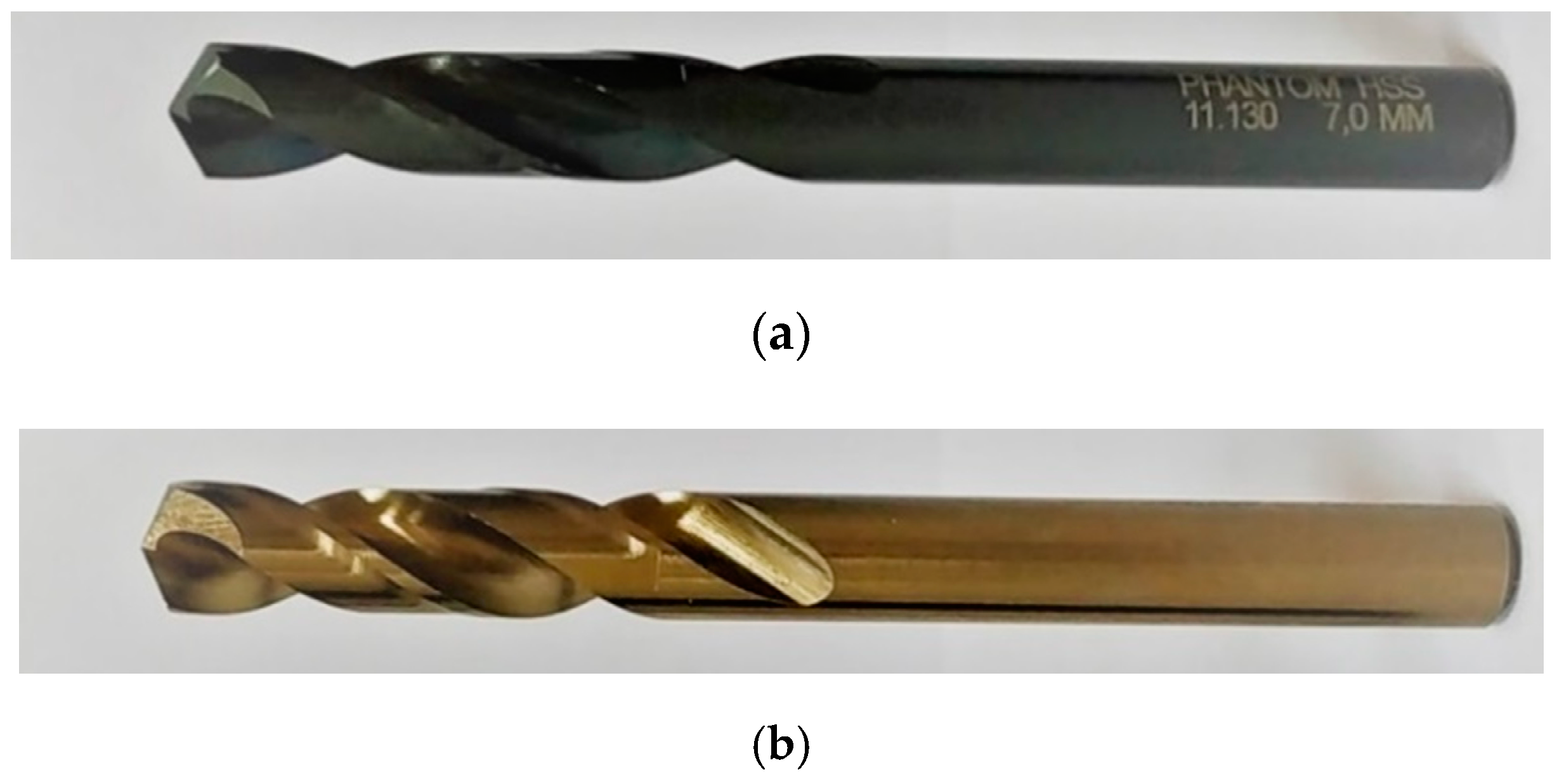
Two types of tool were used for the performance of the tests. They were both manufactured by Phantom (Van Ommen B.V., Beekbergen, Gelderland, Netherlands) in HSS, and are called 11.130 (type A), and 11.160 (type B), Figure 1.
These drills are suitable for drilling depths up to three times the diameter. They are manufactured according to DIN 1897 [34], with a straight shank and two flutes of 34 mm. They have a helix shape normal type N according to DIN 1836 [35], and both drill points are sharpened using split form C point in accordance with DIN 1412 [36].
Drilling tests were carried out using a computer numerical control (CNC) controlled vertical machining center Lagun L650 (Lagun Machinery S.L.L., Legutio, Álava, Spain) under dry conditions. The cutting parameters were selected based on solid drilling operations, taking into consideration the values given by the manufacturer for the group of non-ferrous materials and those used in the previous published studies. Keeping in mind that the present work was focused on repair and/or maintenance, we selected the following test values: cutting speed (S): 60 and 120 m/min; and feed rate (f): 0.2, 0.4, and 0.8 mm/rev; the cutting depth was kept constant at 0.125 mm. All blind holes were drilled to a depth of 20 mm from the top face of the specimen.
In the first stage, drilling tests were performed to enlarge holes from a diameter of 6.75 mm to a diameter of 7 mm, for all the combination of cutting conditions pointed out above, whereupon the machined surface roughness was measured. In a second stage, drilling tests were carried out under the same combination of cutting conditions, in this case from a diameter of 7.25 mm to a diameter 7.50 mm, in order to also evaluate the influence of the diameter of the drill on the surface roughness.
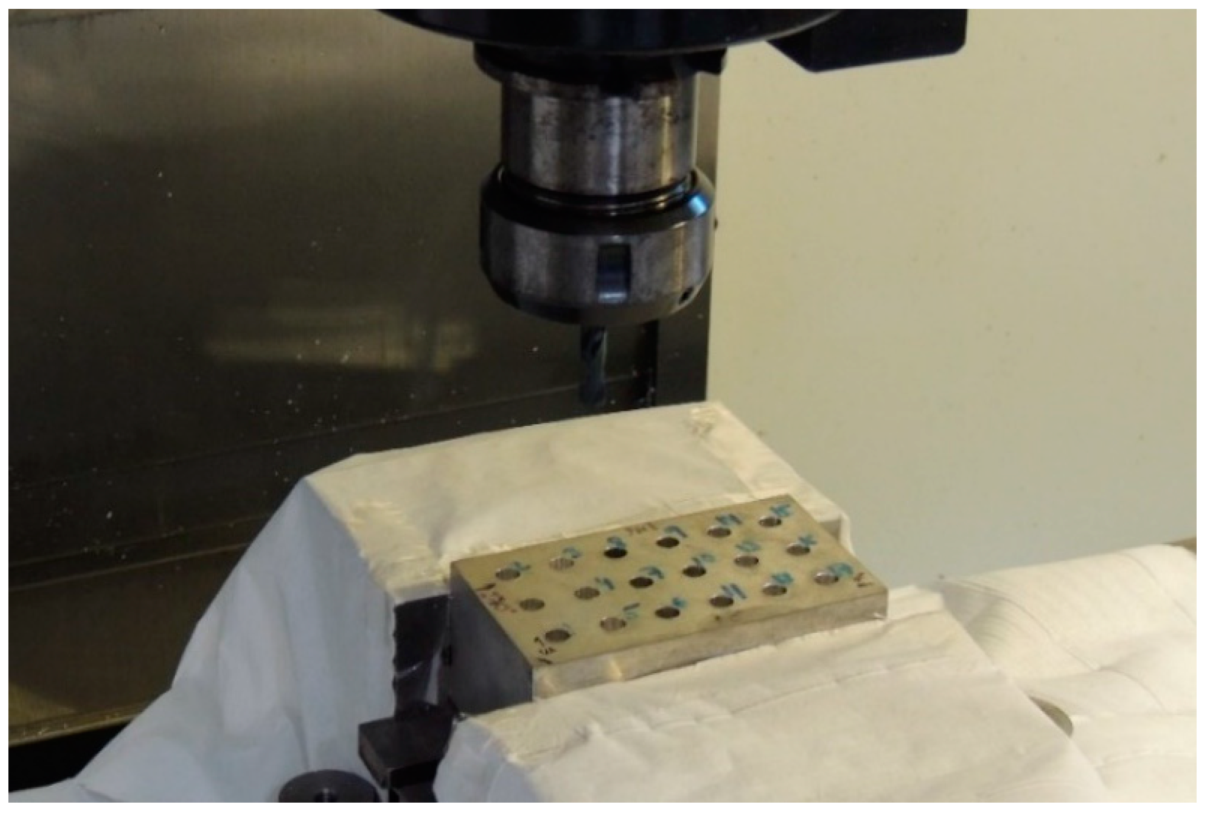
Between each drilling operation, the upper surface of the specimen and its surroundings were cleaned using a brush and pressurized air. Before carrying out the drilling, the periphery of the block was covered with paper, with the purpose of collecting samples of the fragile chips produced in the machining, as shown in the Figure 2. Once the process was finished, the hole and the used drill were marked with a number, and a photographic record of the obtained chips was taken using a Nikon Coolpix P510 digital camera (Nikon, Tokyo, Japan).
The arithmetical mean deviation of the assessed profile, Ra, was used as a response variable to quantify the surface roughness of the machined surface, which according to the standard ISO 4287:1997 [37] is defined as the “arithmetical mean of the absolute ordinate values Z(x) within a sampling length”. The range, that a priori would be expected to be the value of the measured Ra, should be between 0.1 and 2 µm according to ISO 4288:1996 [38], which also established the sampling length (lr) at 0.8 mm and the evaluation length (ln) at 4 mm. Subsequently, after the measurements of the roughness were made, these assumptions were confirmed.
In each of the drilled holes, the roughness was measured on eight different lines. That is, measurements of the Ra were taken along four lines equi-angularly separated by 90° in two cylindrical zones at different distances from the upper surface of the specimen. The first one, named the top plane (TP), was at a distance of 5.5 mm from top face and the second one, named the bottom plane (BP), was at a distance of 15 mm from top face, as can been seen in Figure 3. The measurement length along each one of the eight lines was of 4 mm.
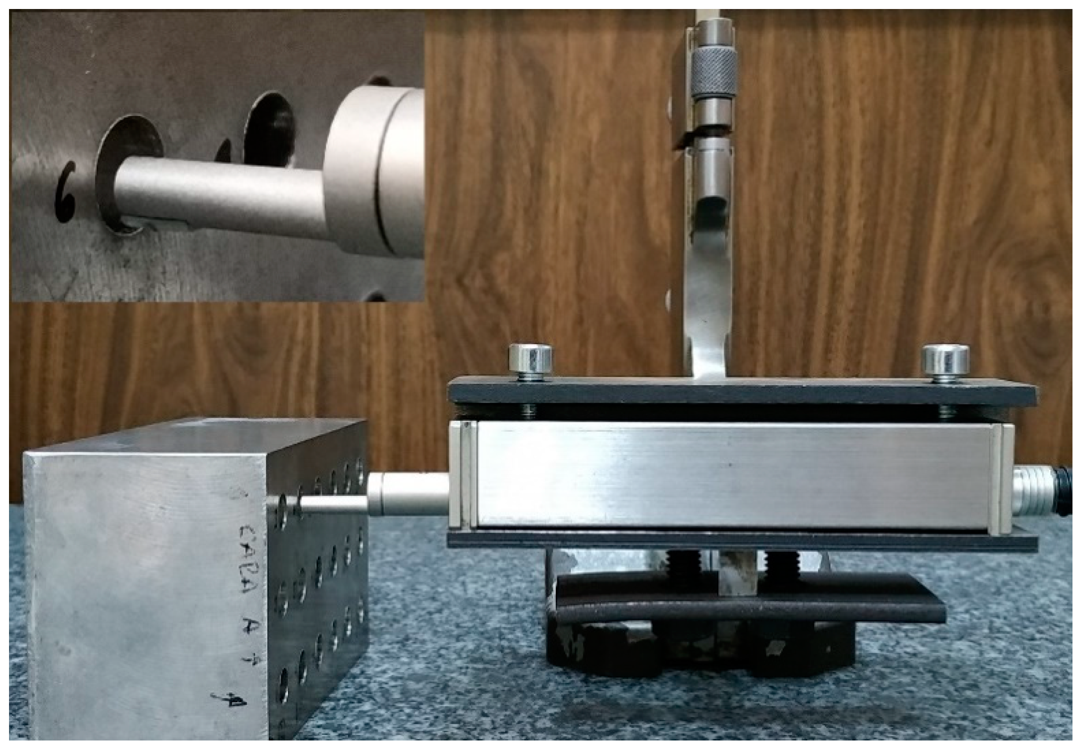
Ra was measured using a contact roughness surface tester Zeiss Handysurf E-35A (Carl Zeiss AG, Oberkochen, Baden-Wurtemberg, Germany). This model has the possibility of exporting the measured data to a computer or displaying it directly on a display panel; it includes several types of parameters of roughness, among them the Ra. To carry out the measurements, the roughness meter and the test block were placed on a surface plate. The probe of the roughness tester is portable, so to perform the eight measurements in each hole, the probe was placed in a tool coupled to a height gauge, allowing for vertical positioning at the desired height, then rotation of the specimen four times to measure the equi-angularly located points, and then positioning of the probe tip at the two established depths. Figure 4 shows the surface tester, probe tip, and positioning system.
Based on all of this, the experimental design was determined, and its objective was to determine the influence of the factors considered in the response variable, that is, the surface roughness studied by the Ra. The experimental design selected was a full factorial design with three factors at two levels, one factor at three levels, and a block at two levels, which is the measurement depth from the upper face of the block, including the performance of a replica, which supposes a total of 96 experimental runs. The considered factors and their levels are included in Table 2.
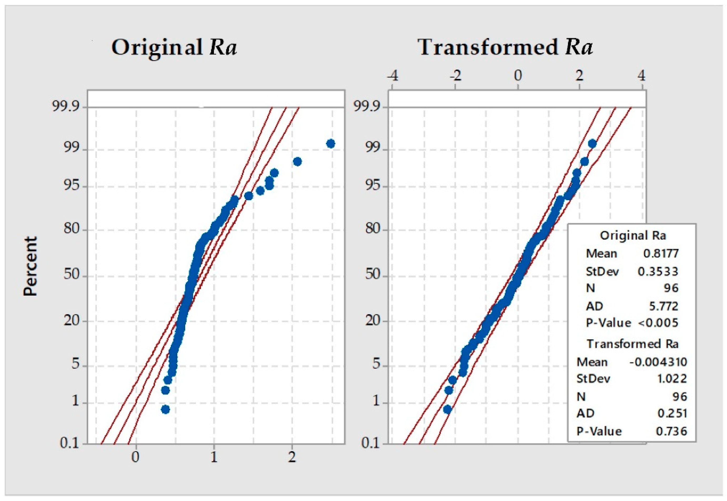
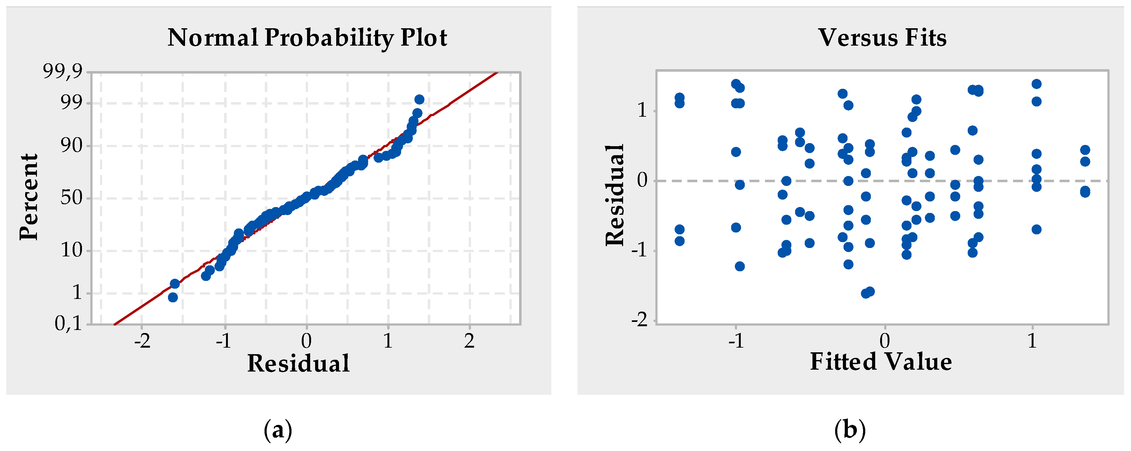
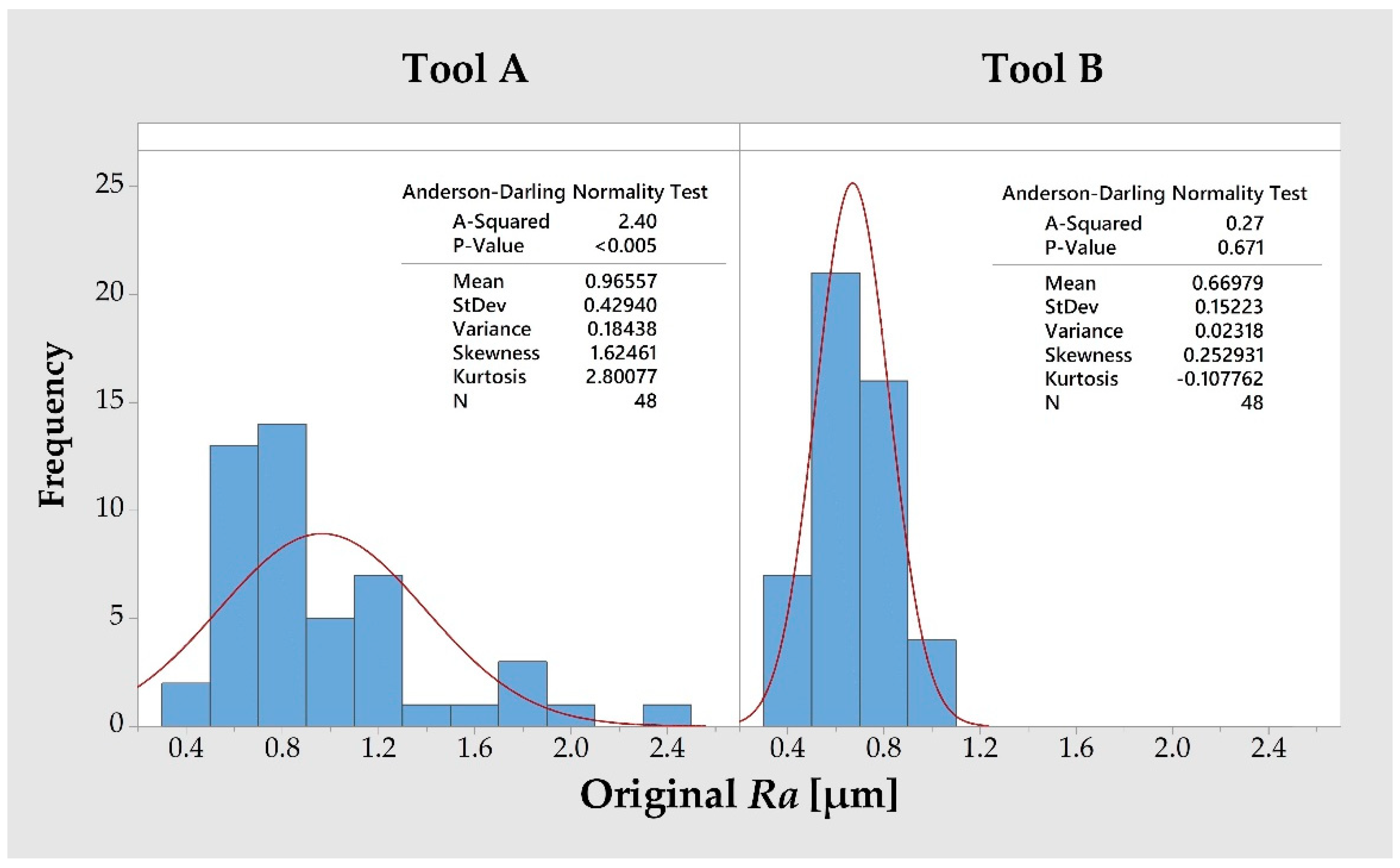
Before carrying out the statistical analysis, the assumption of normality was checked; an Anderson–Darling and Kolmogorov-Smirnov tests data were carried out, which was not overcome, hence a Johnson transformation was carried out. Once the normal data was obtained, the next step was the statistical analysis in order to study the influential factors and interactions on the surface quality measured by Ra. This analysis was performed by the ANOVA.

3. Results and Analysis

3.1. Results

The experiment consisted of carrying out 96 experiments and, for each of them, measuring the roughness on four separate zones at 90° in two cylindrical sections located inside the holes as can be seen in the striped red zones in the Figure 3. To study the measured roughness, it was evaluated considering the average of the four values of Ra measured in each one of the two cylindrical sections located at the different distances from the top face of the specimen in each experimental run. Before carrying out the statistical analysis, the assumption of normality of the average Ra was checked. To do this, normality was assessed using the Anderson–Darling and Kolmogorov–Smirnov tests. The results obtained in both tests are shown in Table 3, and indicate the non-normality of the data and therefore the need to carry out its transformation prior to the statistical study.
Johnson transformation was used to convert the original non-normal data into a standard normal distribution. The best adjustment of the transformation was obtained using the equality function collected in Equation (1), where the transformed roughness values are designated by R a t , being the Ra of the average roughness initial values. The probability plot for the population before and after the transformation can be seen in Figure 5.
R a t =   1.05518 + 1.01828 ×   sinh 1 ( R a 0.562553 0.128499 )
Once the measured roughness data were normalized, it was possible to analyze them using the ANOVA statistical method. For this, the arithmetic mean of the four measured values of the Ra in each elementary run was made. The results obtained in the experimental design are those included in Table 4.

3.2. Analysis and Discussion

From the data obtained, it is clear that the obtained surface quality achieved improved results, independent of the parameters tested. All the roughness values were between 0.38 and 2.49 µm. Only five of the 96 Ra values were above the 1.6 µm that is set as the upper limit in the aeronautical sector. In consideration of the 16%-rule established in the ISO 4288:1996 standard [38], the surface is considered acceptable because only 5.2% exceeded the upper limit.
For the statistical analysis of the transformed Ra values, the Minitab 17 computer program was used. The model was reduced to include only the significant factors, for which a stepwise procedure was followed that eliminates or adds terms to the model using a significance level α = 0.05, starting with an empty model and then adding or removing a term for each step. Table 5 shows the influential factors and interactions, in other words, cutting speed, feed rate, type of tool, diameter, sum of squares, degrees of freedom (DF), mean square, F value, and p-value.
The analysis showed that among the main factors, only the cutting speed, S, and the type of tool, T, were statistically significant for Ra. Regarding the interactions of the factors, there were only two significant second-order interactions: the cutting speed with the diameter, S*D, and the feed rate with the diameter, f*D. The contribution of each effect to the variability is shown in Figure 6. The most important effect was the type of tool with a percentage of 45.25%, the second most important was the interaction of cutting speed with the diameter of the drill with 36.06%, the third was the interaction between feed rate and diameter with 10.18% and the last was the cutting speed with 6.98%.
In Figure 7, it can be seen that the use of a twist drill type B enhances the surface quality of the machined surfaces with respect to those gained from the use of type A. From the untransformed values obtained in the tests, tool A obtained a Ra of 0.97 µm, while type B was 0.67 µm, which represents a considerable improvement. An explanation of this behavior could be the appearance of radial stresses that would produce deformation of the drill and therefore affect the roughness, this would be caused by the small depth of cut of only 0.125 µm in conjunction with the use of a non-high rigidity drill and relatively high feed rates and cutting speed values. Regarding the cutting speed, it is the factor that has the least influence, producing a higher Ra with increasing speed. This result is concordant with those obtained by Weinert et al. for the case of solid drilling [13].
The second effect in terms of importance is the interaction between the cutting speed and the diameter of the drill, S*D, although the diameter itself is not a significant effect. Figure 8 shows that increasing the cutting speed in drills with a diameter of 7 mm causes a lower superficial roughness in contrast to drills with a 7.5 mm diameter.
The influence of the feed rate on the Ra was the opposite and this is explained by the third most important effect: the interaction between feed rate and the diameter of the drill, f*D, as can be seen in the Figure 9. This can be seen most clearly for feed rates of 0.4 and 0.8 mm/rev. Use of 7 mm tools at higher feed rates caused lower Ra values; in contrast, for 7.5 mm tools, the lower Ra values were obtained with lower feed rates.
The results regarding these two interactions of the cutting speed and the feed rate with the diameter of the drill on magnesium alloys are remarkable because the difference between the diameters tested was so small. Further studies should be carried out to clarify this point, considering greater values in the drill diameters studied.
A model of surface roughness was developed to predict the variability in the transformed data, R a t , through Equation (2). This equation uses the significant factors identified by the ANOVA, in other words, cutting speed, type of tool, feed rate, and diameter of the drill, where s, t, f, and d represent their effects, μ is the term to adjust the mean, and ε is the error. The estimation parameters of the equation are included in Table 6.
R a i j k l t =   μ + s i + t j + s d i k + f d l k +   ε i j k l
The residuals of the model were obtained by the difference between measured and predicted values and were used for checking the model hypotheses. As can be seen in Figure 10, the residuals satisfy the normality and homoscedasticity hypothesis; also, no patterns were found in the model.
Once the validity of the model was verified, the inverse of the Johnson transformation used in Equation (1), of the fitted values according to Equation (2), was carried out to predict the surface quality by Ra in re-drilling operations of UNS M11917 magnesium alloys. For this, Equation (3) was used.
R a i j k l =   0.562553 + 0.128499 ×   sinh ( μ + s i + t j + s d i k + f d l k +   ε i j k l + 1.05518 1.01828 )
From Equation (3) and considering both the significant factors identified in the ANOVA, as well as their levels, it was possible to calculate the predicted values of Ra for the different combinations. These values are shown in Table 7 along with the Ra obtained from the values measured in the tests, and the absolute error between the predicted and measured Ra.
The surface roughness values obtained by the model predicted values between 0.52 and 1.23 µm. The absolute error between the measured and predicted values was less than 0.28 µm in all cases except one, in which the error reached 0.88 µm. The minimum Ra value was obtained with the combination of a cutting speed of 60 m/min, type of tool B, feed rate of 0.4 mm/rev, and by using a drill with a 7.5 mm diameter.

4. Technological Discussion

For the framework in which the present study was set up, that of enlarging holes with a low depth of cut by drilling in magnesium alloy UNS M11917, it is important to highlight some technological aspects with implications to the practical application of these operations, mainly in the aerospace sector.
Considering all the tests carried out and according the 16%-rule established in the ISO 4288:1996 standard [38], it can be affirmed that within the margins of the levels and factors tested, the surface quality would be within the quality requirements established in this sector (0.8 µm < Ra < 1.6 µm) [31,32]. Of all the 96 measured Ra values, only five of them were above the upper limit, and those five were drilled using the type A drill. From this it follows, in addition to be the main significant factor, the importance of the type of drill in the performance of these operations.
It is of great importance to carry out these maintenance and/or repair operations in the shortest time possible, meeting the quality standards required for the parts, so it is important to optimize the rate of material removal (RMM). According to Astakhov [39], this rate is directly proportional to the product of the feed rate by the cutting speed, f*S. Therefore, a way of increasing productivity and improving process time is to select the highest feed rate and cutting speed values, that is, 0.8 mm/rev and 120 m/min, respectively. Using these operating parameters, the average Ra values of 0.6 µm for the type B tool and 0.9 µm for type A were obtained.
The type of tool is the most important factor in terms of its influence on the Ra. The Anderson–Darling test shows clearly that for the case of type B drills, the population follows a normal distribution. However, for the case of the type A drill, with a value of p < 0.005, the Anderson–Darling test confirms that it follows a non-normal distribution with a strong asymmetry and positive kurtosis, as seen in Figure 11 with its displacement to the right. An explanation of this phenomenon could be in the appearance of greater radial efforts that, due to the low rigidity of the drills, give rise to deformations that affect the surface quality. Subsequent studies must to be carried out to confirm this hypothesis.

5. Conclusions

This experimental study on the small-scale re-drilling operations in magnesium alloy UNS M11917 within the maintenance and/or repair processes of pieces in the aerospace sector, confirms that it is possible to perform such operations in a way that satisfies the requirements of the surface quality and safety and, at the same time, under environmentally friendly conditions, that is, using dry machining or without the use of lubricant coolants. The most important factor to consider is the type of tool used, obtaining the best results with type B drills, which have a point angle of 135°, compared to type A drills, which have a point angle of 118°. However, further studies have to corroborate if, besides the point angle, other variables of the drill, such as the type of coating, affect the surface quality. Using that type of drill and choosing the highest values in the cutting parameters, that is, a feed rate of 0.8 mm/rev and a cutting speed of 120 m/min, a surface roughness was obtained of approximately half of the maximum limit considered within this sector, in other words, 0.8 µm.
The depth from the upper surface of the specimens did not present a statistical influence on the roughness, so it can be considered constant throughout the depth of the drilling holes, which in this study was 20 mm. Contrary to what was initially assumed, feed rate did not have an influence on surface roughness. This result is consistent with some other work on solid drilling operations in similar magnesium alloys, however, there are other works that show contrary data. Feed rate does have a second-order influence in its interaction with the diameter of the drill, but its influence value is small in relation to the other significant factors.

Author Contributions

Conceptualization, E.M.R., B.d.A., F.B., and J.P.D.; Methodology, E.M.R., B.d.A., F.B., and J.P.D.; Software, E.M.R., B.d.A., and F.B.; Validation, E.M.R., B.d.A., F.B., and J.P.D.; Formal analysis, E.M.R., B.d.A., and F.B.; Investigation, E.M.R., B.d.A., F.B., and J.P.D.; Resources, E.M.R., B.d.A., F.B., and J.P.D.; Data curation, E.M.R., B.d.A., and F.B.; Writing—original draft preparation, F.B.; Writing—review and editing, E.M.R., B.d.A., F.B., and J.P.D.; Visualization, E.M.R., B.d.A., and F.B.; Supervision, E.M.R., B.d.A., and J.P.D.; Project administration, E.M.R. and B.d.A.; Funding acquisition, E.M.R., B.d.A., and F.B.

Funding

This research was funded by the Ministry of Economy and Competitiveness and the Industrial Engineering School-UNED (DPI2014-58007-R; Ref: 2019-ICF03 and Ref: 2019-ICF05).

Acknowledgments

The authors thank the Research Group of the UNED “Industrial Production and Manufacturing Engineering (IPME)” for the support given during the development of this work and to the Grupo Antolín for donating the materials used in this work.

Conflicts of Interest

The authors declare no conflict of interest.

References

  1. Rubio, E.M.; Villeta, M.; Valencia, J.L.; Sáenz de Pipaón, J.M. Experimental Study for Improving the Repair of Magnesium–Aluminium Hybrid Parts by Turning Processes. Metals 2018, 8, 59. [Google Scholar]
  2. Kainer, K. Challenges for Implementation of Magnesium into More Applications. In Magnesium Technology 2016; Springer International Publishing: Basel, Switzerland, 2016; pp. 5–6. [Google Scholar]
  3. Bhowmick, S.; Lukitsch, M.J.; Alpas, A.T. Dry and minimum quantity lubrication drilling of cast magnesium alloy (AM60). Int. J. Mach. Tools Manuf. 2010, 50, 444–457. [Google Scholar] [CrossRef]
  4. Pantelakis, S.G.; Alexopoulos, N.; Chamos, A. Mechanical performance evaluation of cast magnesium alloys for automotive and aeronautical applications. J. Eng. Mater. Technol. 2007, 129, 422–430. [Google Scholar] [CrossRef]
  5. Mouritz, A.P. Introduction to Aerospace Materials; Elsevier: Amsterdam, The Netherlands, 2012; ISBN 978-0-85709-515-2. [Google Scholar]
  6. Fores, F.H.; Eliezer, D.; Aghion, E. How to Increase the use of Magnesium in Aerospace Applications. In Proceedings of the 2nd Israeli International Conference on Magnesium Science and Technology, Dead Sea, Israel, 1 January 2000. [Google Scholar]
  7. Fleming, S. An Overview of Magnesium based Alloys for Aerospace and Automotive Applications. Available online: https://pdfs.semanticscholar.org/5596/35646ba740d5fcb9a308e384a1b6cef46f2e.pdf (accessed on 20 June 2019).
  8. Gwynne, B. Magnesium Alloys in Aerospace Applications, Past Concerns, Current Solutions. Available online: https://www.fire.tc.faa.gov/2007conference/files/Materials_Fire_Safety/WedAM/GwynneMagnesium/GwynneMagnesiumPres.pdf (accessed on 20 June 2019).
  9. Sáenz de Pipaón, J.M. Diseño y Fabricación de Probetas de Componentes Híbridos con Aleaciones de Magnesio para Ensayos de Mecanizado. Ph.D. Thesis, Universidad Nacional de Educación a Distancia, Madrid, Spain, December 2013. [Google Scholar]
  10. Carou, D.; Rubio, E.M.; Davim, J.P. Machinability of Magnesium and Its Alloys: A Review. In Traditional Machining Processes: Research Advances; Davim, J.P., Ed.; Materials Forming, Machining and Tribology; Springer Berlin Heidelberg: Berlin, Heidelberg, 2015; pp. 133–152. ISBN 978-3-662-45088-8. [Google Scholar]
  11. Joksch, S. Safe and Economically Efficient Use of Coolants in Mechanical Processing of Magnesium Alloys.; Wiley Online Library: Hokoben, NJ, USA, 2004; pp. 888–894. [Google Scholar]
  12. Villeta, M.; Rubio, E.M.; De Pipaón, J.S.; Sebastián, M.A. Surface finish optimization of magnesium pieces obtained by dry turning based on Taguchi techniques and statistical tests. Mater. Manuf. Process. 2011, 26, 1503–1510. [Google Scholar] [CrossRef]
  13. Weinert, K.; Liedschulte, M.; Opalla, D.; Schroer, M. High-Tech Machining of Magnesium and Magnesium Composites. Magnes.-Alloys Technol. 2004, 130–151. [Google Scholar]
  14. Froes, F.; Eliezer, D.; Aghion, E. The science, technology, and applications of magnesium. JOM J. Miner. Met. Mater. Soc. 1998, 50, 30–34. [Google Scholar] [CrossRef]
  15. Tikal, F.; Schmier, M.; Vollmer, C. High-speed-drilling in AZ91 D without Lubricoolants. Magnes. Alloys Their Appl. 2000, 371–379. [Google Scholar]
  16. Tomac, N.; Tønnessen, K.; Rasch, F. Safe machining of magnesium. In Advanced Manufacturing Systems and Technology; Springer: Vienna, Austria, 1996; pp. 177–184. [Google Scholar]
  17. Habashi, F. Alloys: Preparation, Properties, Applications; John Wiley & Sons: Hoboken, NJ, USA, 2008; ISBN 978-3-527-61192-8. [Google Scholar]
  18. Akyuz, B. Machinability of magnesium and its alloys. TOJSAT Online J. Sci. Technol. 2011, 1, 31–38. [Google Scholar]
  19. Rubio, E.M.; Valencia, J.L.; Saá, A.J.; Carou, D. Experimental study of the dry facing of magnesium pieces based on the surface roughness. Int. J. Precis. Eng. Manuf. 2013, 14, 995–1001. [Google Scholar] [CrossRef]
  20. Rubio, E.M.; Villeta, M.; Carou, D.; Saá, A. Comparative analysis of sustainable cooling systems in intermittent turning of magnesium pieces. Int. J. Precis. Eng. Manuf. 2014, 15, 929–940. [Google Scholar] [CrossRef]
  21. Rubio, E.M.; Valencia, J.L.; de Agustina, B.; Saá, A.J. Tool selection based on surface roughness in dry facing repair operations of magnesium pieces. Int. J. Mater. Prod. Technol. 2014, 48, 116–134. [Google Scholar] [CrossRef]
  22. Carou, D.; Rubio, E.M.; Lauro, C.H.; Davim, J.P. Experimental investigation on finish intermittent turning of UNS M11917 magnesium alloy under dry machining. Int. J. Adv. Manuf. Technol. 2014, 75, 1417–1429. [Google Scholar] [CrossRef]
  23. Gariboldi, E. Drilling a magnesium alloy using PVD coated twist drills. J. Mater. Process. Technol. 2003, 134, 287–295. [Google Scholar] [CrossRef]
  24. Bhowmick, S.; Alpas, A.T. The role of diamond-like carbon coated drills on minimum quantity lubrication drilling of magnesium alloys. Surf. Coat. Technol. 2011, 205, 5302–5311. [Google Scholar] [CrossRef]
  25. Wang, J.; Liu, Y.B.; An, J.; Wang, L.M. Wear mechanism map of uncoated HSS tools during drilling die-cast magnesium alloy. Wear 2008, 265, 685–691. [Google Scholar] [CrossRef]
  26. Berzosa, F.; de Agustina, B.; Rubio, E.M. Tool Selection in Drilling of Magnesium UNSM11917 Pieces under Dry and MQL Conditions Based on Surface Roughness. Adv. Mater. Process. Technol. Conf. 2017, 184, 117–127. [Google Scholar] [CrossRef]
  27. Bagci, E.; Ozcelik, B. Effects of different cooling conditions on twist drill temperature. Int. J. Adv. Manuf. Technol. 2007, 34, 867–877. [Google Scholar] [CrossRef]
  28. Weinert, K.; Lange, M. Machining of magnesium matrix composites. Adv. Eng. Mater. 2001, 3, 975–979. [Google Scholar] [CrossRef]
  29. Carou, D.; Rubio, E.M.; Davim, J. Analysis of ignition risk in intermittent turning of UNS M11917 magnesium alloy at low cutting speeds based on the chip morphology. Proc. Inst. Mech. Eng. Part B J. Eng. Manuf. 2014, 229, 365–371. [Google Scholar] [CrossRef]
  30. Rubio, E.; Villeta, M.; Valencia, J.; Sáenz de Pipaón, J. Cutting Parameter Selection for Efficient and Sustainable Repair of Holes Made in Hybrid Mg–Ti–Mg Component Stacks by Dry Drilling Operations. Materials 2018, 11, 1369. [Google Scholar] [CrossRef]
  31. Villeta, M.; de Agustina, B.; Sáenz de Pipaón, J.M.; Rubio, E.M. Efficient optimisation of machining processes based on technical specifications for surface roughness: application to magnesium pieces in the aerospace industry. Int. J. Adv. Manuf. Technol. 2011, 60, 1237–1246. [Google Scholar] [CrossRef]
  32. American Society of Mechanical Engineers. ANSI/ASME B46.1-2009. Surface Texture (Surface Roughness, Waviness, and Lay); American Society of Mechanical Engineers: New York, NY, USA, 2010. [Google Scholar]
  33. Luan, B.L.; Gray, J.; Yang, L.X.; Cheong, W.J.; Shoesmith, D. Surface modification of AZ91 magnesium alloy. Trans Tech Publ. 2007, 546, 513–518. [Google Scholar]
  34. Deutsches Institut für Normung e.V. DIN 1897; Parallel Shank Twist Drills, Stub Series; Deutsches Institut Fur Normung E.V.: Berlin, Germany, 2006. [Google Scholar]
  35. Deutsches Institut für Normung e.V. DIN 1836; Groups of Tool Application for Chip Removal es of Points; Deutsches Institut für Normung, e.V.: Berlin, Germany, 1984. [Google Scholar]
  36. Deutsches Institut für Normung e.V. DIN 1412; Twist Drills Made of High-Speed Steel - Shapes of Points; Deutsches Institut für Normung e.V.: Berlin, Germany, 2001. [Google Scholar]
  37. International Organization for Standardization. ISO 4287. Geometrical Product Specifications (GPS). Surface Texture: Profile Method. Terms, Definitions and Surface Texture Parameters; International Organization for Standardization: Geneva, Switzerland, 1997. [Google Scholar]
  38. International Organization for Standardization. ISO 4288. Geometrical Product Specifications (GPS). Surface Texture: Profile Method. Rules and Procedures for the Assessment of Surface Texture; International Organization for Standardization: Geneva, Switzerland, 1996. [Google Scholar]
  39. Astakhov, V.P. Drills: Science and Technology of Advanced Operations; CRC Press: Boca Raton, FL, USA, 2014; ISBN 978-1-4665-8435-8. [Google Scholar]
Figure 1. Twist drills for the tests; (a) Tool type A; (b) Tool type B.
Metals 09 00740 g001
Figure 2. Detail of the method for collecting chips.
Metals 09 00740 g002
Figure 3. Cylindrical sections inside the holes where the measurements of roughness were taken for the evaluation of average roughness (Ra) (striped in red) and, in each one of them, the specific zones to take the measurements are defined by the four points separated to 90° and marked as 1, 2, 3, and 4.
Metals 09 00740 g003
Figure 4. Zeiss Handysurf E-35A roughness tester, positioning system, and probe tip.
Metals 09 00740 g004
Figure 5. Probability plots of original non-normal data and Johnson transformed data of the Ra.
Metals 09 00740 g005
Figure 6. Percentage of contribution to the variability of the ANOVA model for each effect.
Metals 09 00740 g006
Figure 7. Effects on the transformed Ra of the significant factors.
Metals 09 00740 g007
Figure 8. Box and whiskers plot graph for interactions between cutting speed and diameter, S*D.
Metals 09 00740 g008
Figure 9. Interaction graph between feed rate and diameter, f*D.
Metals 09 00740 g009
Figure 10. (a) Probability plot and (b) residuals versus predicted values for the model.
Metals 09 00740 g010
Figure 11. Histogram of data with an overlaid normal curve of the original Ra for tool types A and B.
Metals 09 00740 g011
Table 1. Mechanical properties of die casting magnesium alloy UNS M11917.
Brinell Hardness63 HB
Tensile strength230 MPa
Yield strength173 MPa
Elongation3%
Modulus of elasticity44.8 GPa
Charpy impact2.7 J
Table 2. Factors and their levels.
FactorLevels Values
Cutting speed, S, (m/min)60, 120
Feed rate, f, (mm/rev)0.2, 0.4, 0.8
Type of tool, TA, B
Diameter, D, (mm)7, 7.5
Measurement depth, MD, (mm)Top plane (TP), bottom plane (BP)
Table 3. The p-values of tests for normality of Ra.
FactorAnderson–DarlingKolmogorov–Smirnov
Original Data<0.005<0.010
Transformed data0.736>0.150
Table 4. Replicas of original and transformed data of Ra in µm, at different measurement depths.
S [m/min]f [mm/rev]TD [mm]Ra Ra t
TPBPTPBP
600.2A7.01.760.851.710.771.880.251.920.53
600.2A7.50.570.780.470.82−1.700.42−0.990.29
600.2B7.00.610.670.580.77−0.890.22−0.68−0.26
600.2B7.50.380.800.74,0.560.12−1.03−2.210.34
600.4A7.01.261.120.791.060.311.041.391.17
600.4A7.50.560.710.510.67−1.40−0.26−1.01−0.02
600.4B7.00.630.820.580.96−0.910.84-0.500.42
600.4B7.50.670.410.680.37−0.20−2.23−0.26−2.08
600.8A7.00.670.900.810.730.400.08−0.230.66
600.8A7.50.661.150.691.24−0.141.35−0.341.21
600.8B7.00.560.710.740.740.110.12−1.01−0.02
600.8B7.50.610.490.540.48−1.21−1.65−0.66−1.58
1200.2A7.00.871.070.610.78−0.630.280.581.07
1200.2A7.51.012.060.792.490.322.410.942.15
1200.2B7.00.470.690.680.58−0.19−0.89−1.72−0.12
1200.2B7.50.830.610.590.69−0.78−0.130.46−0.68
1200.4A7.00.661.700.641.20−0.451.29−0.311.88
1200.4A7.51.000.680.880.750.620.130.92−0.19
1200.4B7.00.550.731.010.790.950.31−1.110.08
1200.4B7.50.950.540.510.73−1.440.050.81−1.21
1200.8A7.00.650.460.710.60−0.01−0.70−0.35−1.75
1200.8A7.51.141.441.111.581.151.761.201.61
1200.8B7.00.470.740.620.80−0.590.36−1.680.10
1200.8B7.50.710.810.770.990.230.90−0.020.40
*S = cutting speed; f = feed rate; T = type of tool; D = diameter; R a t = transformed Ra.
Table 5. Analysis ANOVA of the transformed Ra. DF = degrees of freedom.
EffectDFSum of SquaresMean SquareF-Valuep-Value
S*12.8322.83194.630.034
T118.34718.347029.980.000
S*D114.62114.620523.890.000
f*D28.2594.12976.750.002
Error9055.0810.6120--
Total9599.140---
Table 6. Estimation parameters of the predictive model.
ParameterDesignationEstimationParameterDesignationEstimation
60 (m/min) s 1 −0.17180.2 (mm/rev)*7 mm f d 11 −0.027
120 (m/min) s 2 0.17180.2 (mm/rev)*7.5 mm f d 12 0.027
A t 1 0.43720.4 (mm/rev)*7 mm f d 21 0.372
B t 2 −0.43720.4 (mm/rev)*7.5 mm f d 22 −0.372
60 (m/min)*7 mm s d 11 0.39030.8 (mm/rev)*7 mm f d 31 −0.345
60 (m/min)*7.5 mm s d 12 −0.39030.8 (mm/rev)*7.5 mm f d 32 0.345
120 (m/min)*7 mm s d 21 −0.3903Intercept termµ−0.0043
120 (m/min)*7.5 mm s d 22 0.3903---
Table 7. Predicted Ra, measured Ra, and absolute error for levels and effects combinations.
S* (m/min)Tf (mm/rev)D (mm)Ra Predicted (µm)Ra Measured (µm)Abs. Error (µm)
60B0.47.50.520.670.15
120B0.870.570.480.09
60B0.27.50.570.380.19
120B0.270.610.470.14
60B0.87.50.610.610.00
60B0.870.630.570.06
60A0.47.50.640.570.07
120B0.470.670.560.11
120B0.47.50.670.960.28
60B0.270.680.610.07
120A0.870.700.660.04
60A0.27.50.700.570.13
120B0.27.50.750.840.08
60B0.470.750.640.12
120A0.270.760.870.11
60A0.87.50.770.660.11
60A0.870.790.680.11
120B0.87.50.830.720.12
120A0.470.870.670.21
120A0.47.50.881.000.12
60A0.270.881.760.88
120A0.27.51.051.010.04
60A0.471.051.270.22
120A0.87.51.231.150.09

