Abstract
Under irradiations, mechanical performance of nuclear alloys would degrade due to irradiation induced defects. Different strengthening methods can play a different role in the evolution of the defects. In this study, the effect of four typical strengthening methods including fine grain strengthening, dislocation strengthening, second phase strengthening and solid solutions strengthening on the defect evolutions in bcc iron-based alloys are investigated with rate theory simulations, a technique capable of simulating a long-term evolution of defects caused by irradiations. Simulations show that at high dose, irradiation induced voids become the dominating factor that affect irradiation hardening. Strengthening methods with the enhancement of sink strength (fine grain strengthening, dislocation strengthening and second phase strengthening) have little effects on the evolution of voids, while strengthening method with impediment of migration of defects (solid solutions strengthening) can effectively inhibit the nucleation and growth of voids. For fine grain strengthening and dislocation strengthening, the irradiation hardening is almost kept unchanged when changing grain size and initial dislocation density. For second phase strengthening, the irradiation hardening can be inhibited to some extent by increasing mainly the number density of precipitates. The solid solutions strengthening is the most proper method to inhibit irradiation hardening of bcc iron-based alloy because it can inhibit the development of voids, especially at high dose.
1. Introduction
Material problems have been the major challenges for the development of advanced nuclear systems. The mechanical properties of nuclear materials can be affected under high energy neutron irradiation, which leads to irradiation hardening, irradiation embrittlement and the rise of ductile-brittle transition temperature (DBTT). Bcc (body-centered cubic) iron-based alloys have become the main candidate materials of advanced nuclear energy systems due to their better irradiation swelling resistances compared to fcc (face-centered cubic) austenitic steel [1,2]. However, a large number of voids were found in martensitic steels irradiated in high flux isotope reactor (HFIR) [3]. In addition, irradiation hardening is the key factor that affects the application of bcc iron-based alloys. The performance degradation of nuclear alloys is mainly due to various defects and defect clusters induced by irradiation.
The appearance of irradiation hardening is attributed to the obstacle to the migration of dislocation, which can be caused by dislocation loops, voids and precipitates [4]. Different strengthening methods can be carried out to enhance irradiation hardening resistance of alloys with a different role played in the evolution of the defects. In this study, the effect of four typical strengthening methods including fine grain strengthening, dislocation strengthening, second phase strengthening and solid solutions strengthening on the defect evolutions in bcc iron-based alloy are investigated. Fine grain strengthening, dislocation strengthening and second strengthening correspond to different sink strength of grain boundaries, dislocations and precipitates, respectively, which can affect the absorption of defects. Solid solutions strengthening can change the chemical composition of the nuclear alloy, which causes the change of migration energy of defects, especially vacancies [5].
The investigation of the effects of strengthening methods brings many variables to be considered and it is too difficult to manage solely by experiment. Theoretical simulation has been used as a significant way to observe the evolution of defects and study the mechanism of irradiation effects for its convenience and efficiency. Rate theory can be used to simulate the dynamic evolution of defects and clusters under irradiation from microscopic to mesoscopic scales, and the results of simulation can be directly compared with the experimental observations. A good agreement of rate theory results and experiment for ferritic alloy under electron irradiation was obtained by A. Hardouin Duparc [6]. However, different from the formation of isolated Frankel pairs in cascade under electron irradiation, the cascade clustering should be considered in neutron and ion irradiation. In fact, the simulation of microstructures in iron under Kr ion and neutron irradiation has been conducted by Meslin [7], in which a set of parameters of cascade is also inputted as the initial defect configuration from which long-term defect evolution starts. Cluster dynamics based on rate theory focus on the concentration of point defects and various defect clusters by solving a system of coupling ordinary differential equations (ODEs). T. Jourdan et al. have comprehensively investigated the Fokker–Planck method, a numerical solution of rate equations [8,9]. The evolution of defects in α-Fe under helium irradiation was studied with rate theory [10], in which an effective phase truncation method was proposed. The effects of helium atoms on bubbles in RAFM steel were also simulated with rate theory [11]. However, the simulation of strengthening methods about bcc iron-based alloys have not been investigated systemically. In present work, the rate theory simulation of various strengthening methods is implemented by using different grain sizes, dislocation densities, number densities and sizes of precipitates, as well as migration energy of vacancies.
2. Method
2.1. Rate Equations
In this study, cluster dynamics code RADAFP (RAdiation DAmage simulation with Fokker–Planck method) is used to simulate the evolution of microstructures in pure iron and bcc iron-based alloy under neutron irradiation. RADAFP is developed by our team to simulate and predict the evolution of irradiation induced defects/clusters, which is based on the model proposed by Jourdan in [8]. It is written in Fortran and can be either compiled in Windows or Linux operating system for researchers on different platforms. The main contents and methods in RADAFP code are to be described in this section. In RADAFP code, the concentration of clusters depends on their generation rate, the transition rate with adjacent clusters and absorption rate to sinks, where is the number of defects contained in clusters. For interstitial clusters, is positive, and for vacancy clusters is negative. The general form of rate equations can be written as
where is the coordinate in depth. is the generation rate of cluster . means the mobile defects or clusters here, and is the set of all mobile species. is the net flux between and . is the set of all clusters considered in this model. , and are the sink strengths of dislocations, grain boundaries and precipitates. is the diffusion coefficient of cluster and is the thermal equilibrium concentration. In general, except for vacancies. For neutron irradiation, spatial dependency can be neglected due to the approximately balanced distribution of clusters in bulk. Therefore, the last term of Equation (1) can be omitted in present study.
Generation rate is obtained by considering the damage rate of neutron irradiation, which can be calculated through NRT model. In fact, the clusters can be formed directly in cascade under neutron irradiation. So is given by
where is the damage rate of neutron irradiation. is the survival fraction of defects in cascade and is the clustering fraction of in survived defects.
and is written as
where is the absorption rate of by , and is the emission rate of by . The absorption rate can be given as
where is the efficiency factor for the absorption of by due to elastic interaction. is the radius of cluster , which accounts for the geometrical shape. is the reaction distance with a normal value of zero [12]. In present work, dislocation loop is considered as toroidal structure and void is spherical, so we can get
The form of efficiency factor in ref. [13] is used here, which is given by
where is the absorption efficiency of dislocation. The emission rate can be deduced from equilibrium condition, so
where is the binding energy of cluster to cluster , the Boltzmann constant and the temperature. In present work, only point defects (interstitial atoms and vacancies) can be emitted by corresponding clusters.
The binding energy can be calculated from molecular dynamics (MD) or other atomistic computations. However, a simpler method named capillary approximation can be used here to obtain the binding energy [14]:
where and are the formation energy of interstitial atoms and vacancies respectively, which can be obtained from atomistic computations as input parameters of RADAFP code.
The diffusion coefficients of defects or clusters are functions of the jump frequencies, and they are described with Arrhenius relationship:
where is the pre-exponential factor and the migration energy of cluster .
The sink strength of dislocation, grain boundary and precipitate are given by
where is dislocation density, the number density of precipitates, the average size and the efficiency factor of precipitates. It is noticed that precipitates are simply considered as spherical sinks without the evolution of their density and size in present model.
2.2. Fokker–Planck Method
When long-term evolution is simulated, the size of clusters can be very large and the number of coupled equations is also large, which make it unfeasible to solve the ODEs systems directly. Therefore, the appropriate approximation is necessary for the sake of simplicity. The Fokker–Planck (FP) method is used here to greatly decrease the number of ODEs [6,8,9]. Cluster can be considered as a grid point in cluster space. We can make a Taylor expansion for and in Equations (3a) and (3b), then plug it to Equation (1) and obtain the following FP equation:
where and are related to the growth and diffusion in cluster space respectively, which can be written as
The discretization of FP equation is carried out with central difference method, which change the Equation (11) to the following form:
with the grid points in cluster space set as
The width of uniform grid in interstitial cluster space is given by
where is a real number larger than 1 to control the mesh in cluster space. An analogous form can be obtained in vacancy part.
2.3. Evolution of Dislocation Network
In the case that irradiation dose is high enough, the dislocation density in the matrix can be changed, which has an effect on the evolution of microstructures. The neutron irradiation for solution-annealed 316 stainless steel had indicated that the low initial dislocation density would lead to the increase of dislocation density and then a saturation, while the decrease of dislocation density would appear for a cold-worked one, which has high initial dislocation density [15]. In present work, the model for evolution of dislocation proposed by Jourdan in [16] is considered, in which two mechanism are involved. The first mechanism is the incorporation of dislocation loops, and the second one is the dipole annihilation.
The dislocations and loops are mobile under elevated temperature and stress. When the loops meet with dislocations or other loops, they can interact with each other and incorporate to dislocation network, which leads to the increase of dislocation density. Meanwhile, the rise of dislocation density can inhibit the growth of loops in turn. To determine the incorporation of loops, the circumferences of loops per unit volume are added to dislocation density. Therefore, the contribution of loops’ incorporation can be written as
where discussed in the previous section corresponds to the net growth rates of loops, is the fraction of interstitial cluster to interact with dislocation network. The form of had been derived in [16], which can be given as
where with the total dislocation density (dislocation network and loops) . is the minimum distance between dislocations and is set to zero in this work, the standard deviation for the spatial distribution of dislocations.
The approach adopted by Wolfer and Glasgow [15] as well as Jourdan [16] is closely followed to simulate dipole annihilation. The annihilation of converging dipole is determined by the average time for two dislocations to climb. The climb velocity of one dislocation is written as
with
where and are thermally activated velocity and irradiation-induced velocity respectively, the shear modulus and the Poisson’s ratio. is the distance between dipoles and can be given as the following formula with the consideration of dipoles that are not converging:
The time to climb and annihilation is
Then the contribution of dipole annihilation can be written as
where is an adjustable parameter to fit the simulation results and experimental observations.
Finally, the change rate of dislocation density is the sum of these two parts:
3. Results
3.1. Simulation of Pure Iron under Neutron Irradiation
In order to verify the validity of the model used in present work and RADAFP code, A simulation of pure iron under neutron irradiation is implemented. The TEM results reported in [17] have been used to make a comparison with simulation results. Pure iron was irradiated at 300 °C to the dose of 0.2 dpa with the damage rate of 1.3 × 10⁻⁷ dpa/s. The parameters used for this test case are from reference [7], and are listed in Table 1. The results of size distribution of dislocation loops at 0.2 dpa are shown in Figure 1.

Table 1.
Parameters used for the simulation of pure iron under neutron irradiation.
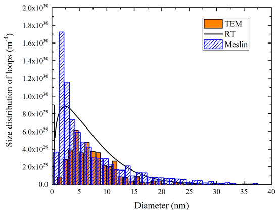
Figure 1.
Distribution of dislocation loops in pure iron under neutron irradiation at 0.2 dpa.
It can be seen that a very good agreement between simulation and experiment results is obtained, except for the deviation for small clusters. The slightly higher distribution function of simulation might be explained with the lack of statistics of small loops, because the observations of small and almost invisible microstructures are difficult and can lead to the statistical error in the experiment. It is noticed that the simulation results without evolution of dislocation network do not coincide with the results of Meslin [7], due to the absence of some necessary information such as specific formulas about absorption rates and efficiency factors and the numerical method to solve rate equations, which were not reported in reference [7]. However, a better fit with experimental observation is obtained in our model than the simulation of Meslin for the consideration of the evolution of the dislocation network. The good fit with TEM results indicates that the model and parameters for pure iron are reliable. It is noteworthy that parameters for the simulation of bcc iron-based alloy in next section can be obtained by proper adjustment of migration energy in pure iron.
3.2. Simulation of bcc Iron-Based Alloy with Fine Grain Strengthening
The solutes and impurity atoms in alloy can combine with vacancies and reduce the mobility of them, which cause the increase of migration energy of vacancies. In the present study, a representative value of the migration energy of vacancy in bcc iron-based alloy is selected as 0.9 eV, which is higher than the value of 0.83 eV in pure iron. This value of 0.9 eV is obtained by N. Hashimoto in reference [5] with the experiment of temperature dependence of loop growth in bcc Fe-8Cr alloy. In addition, the number density and size of precipitates in bcc iron-based alloy are set as 2 × 10²⁰ m−3 and 50 nm, respectively. To calculate irradiation induced hardening, the contributions of dislocation loops, voids and precipitates are considered. The linear superposition [18] is used in this work and can be given as
where , , are the obstacle strength factor of loops, voids and precipitates respectively. The related descriptions about obstacle strength factors are from reference [4] (page 606), in which the contributions of dislocation loops, voids and precipitates to hardening are analyzed and various obstacle strength factors are listed with a table. is Taylor factor. and are number density and average diameter of obstacle.
For fine grain strengthening, different grain sizes are simulated. In present work, five values of as 0.5 μm, 1.0 μm, 10.0 μm, 50.0 μm and 200.0 μm are used to investigate the effects of grain size on the evolution of microstructures. The number density and average diameter of loops (NI, DI) and voids (NV, DV) in bcc iron-based alloy under neutron irradiation to the dose of 30 dpa are shown in Figure 2a,b. With the development of irradiation, the number density of loops increases and then tends to reach saturation, while the size of loops, the density and size of voids increase and the rates of increases become slow at high dose. Meanwhile, with the decrease of grain size, the density of loops increases while the size of loops just slightly changes. The size of loops and voids are almost independent with grain size. The distributions of loops at 0.2 dpa, 5 dpa and 30 dpa are shown in Figure 2c. We can find that the peak value increases and the distribution around the peak broadens when grain size decreases, and the peak position keeps almost unchanged when the dose reaches 30 dpa.
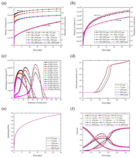
Figure 2.
Rate theory simulation results with various grain sizes. (a) Number density and diameter of loops. (b) Number density and diameter of voids. (c) Distribution of loops at 0.2 dpa, 5 dpa and 30 dpa. (d) Dislocation density. (e) Hardening. (f) Contribution of loops (L), voids (V) and precipitates (P) to hardening.
The dislocation evolutions with irradiation dose for various grain sizes are shown in Figure 2d. The dislocation density decreases slightly for the dipoles annihilation and then increases rapidly due to incorporation of large number of loops. Finally, the annihilation and incorporation are balanced, which lead to the saturation of dislocation networks. With the decrease of grain size, the dose which corresponds to dramatic increasing dislocation density is higher, but the saturated dislocation densities are the same for five grain sizes.
The hardening caused by dislocation loops and voids increases with the development of irradiation and the increase rate is slower at high dose (Figure 2e). But the difference of hardening between five grain sizes is too small to be observed. It is interesting to study the contribution of dislocation loops, voids and precipitates to whole hardening with the development of irradiation. From Figure 2f, we can see that the contribution of loops (L) and voids (V) are small while the contribution of precipitates (P) is large in the early stage of irradiation. With the development of irradiation, the contribution of loops to the hardening increases first and reaches to a peck value at around 0.01 dpa then decreases and approaches to a small value of less than 15%. The contribution of voids increases with dose and reaches a predominant value of approximately 85% due to large number of vacancies nucleate, while the contribution from precipitates is suppressed quickly to a negligible value. It can be seen that the effects of grain size on clusters’ contribution to hardening only exist before 1 dpa and disappear at higher dose.
3.3. Simulation of bcc Iron-Based Alloy with Dislocation Strengthening
For dislocation strengthening, different initial dislocation densities are simulated. In the present work, five values of initial dislocation densities as 1012 m−2, 1013 m−2, 1014 m−2, 1015 m−2 and 1016 m−2 are used to investigate the effects of dislocation to the evolution of microstructures. In Figure 3a,b, the trend of evolution of loops and voids are the same as the previous section. The number density of loops increases with the initial dislocation density, while the density of voids decreases slightly. No differences of the size of voids between various are observed. It can be seen from Figure 3c that the peak of distribution shifts towards a larger size with the development of irradiation. The slight broadening of distribution can be seen with the initial dislocation density increases from 1012 m−2 to 1015 m−2, while the peak becomes narrow when reaches to 1016 m−2.
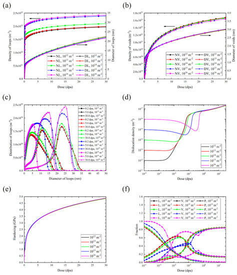
Figure 3.
Rate theory calculations with various initial dislocation densities. (a) Number density and diameter of loops. (b) Number density and diameter of voids. (c) Distribution of loops at 0.2 dpa, 5 dpa and 30 dpa. (d) Dislocation density. (e) Hardening. (f) Contribution of loops (L), voids (V) and precipitates (P) to hardening.
The dislocation density decreases at the original period of irradiation, and the decrease trend is most obvious for = 1016 m−2 (Figure 3d). Then, the dislocation densities increase rapidly and finally reach to the same saturated value under various initial dislocation density values.
Similar to the unchanged hardening with various grain sizes, the hardening under different initial dislocation densities can be seen as almost the same (Figure 3e). As we can see from Figure 3f, the high value cause some fluctuations in the contribution of loops and voids before 1 dpa, but the overall trends at high dose are not affected by initial dislocation density.
3.4. Simulation of bcc Iron-Based Alloy with Second Phase Strengthening
To simulate second phase strengthening, various values of densities and diameters of precipitates in bcc iron-based alloy are considered. In fact, it is the product of precipitate density and diameter that has influences on the evolution of microstructures and hardening, without the evolution of themselves in this model. Therefore, five values of are set, which corresponds to sizes and densities of precipitates as (50 nm, 2 × 10¹⁸ m−3), (5 nm, 2 × 10²⁰ m−3), (50 nm, 2 × 10²⁰ m−3), (250 nm, 2 × 10²⁰ m−3) and (50 nm, 1 × 10²² m−3). The results with different values of are shown in Figure 4a–f. As we can see from Figure 4a, the number density of loops increases with the increase of , while the size of loops decreases slightly. The different results about voids are shown in Figure 4b. The density and size of voids decrease slightly with the increase of . The broadening of loop distribution can be observed with the increase of , but the highest value of causes the narrowing of loops’ distribution in Figure 4c. When dislocation density greatly increases, the corresponding dose is higher with the bigger value of (Figure 4d).
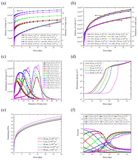
Figure 4.
Rate theory calculations with various sizes and densities of precipitates. (a) Number density and diameter of loops. (b) Number density and diameter of voids. (c) Distribution of loops at 0.2 dpa, 5 dpa and 30 dpa. (d) Dislocation density. (e) Hardening. (f) Contribution of loops (L), voids (V) and precipitates (P) to hardening.
The rise of value can inhibit the irradiation hardening caused by loops and voids. Simulation results in Figure 4e show that the hardening increases with the increase of value, which can be explained by DBH model that the precipitates can strengthen alloys and the corresponding hardening is proportional to . After irradiation, loops and voids form and induce hardening, but their contribution to hardening both decrease when the value increases. This effect can be ascribed to the fact that the density and size of voids decrease and size of loops also decreases with the increase of value of precipitates, because the increase of the precipitates means the enhancement of defect sinks at the interface between precipitates and grains.
3.5. Simulation of bcc Iron-Based Alloy with Solid Solutions Strengthening
The addition of solute atoms can lead to the increase of migration energy of vacancy and affect the radiation-induced segregation to grain boundaries [19]. The migration energy of vacancy varies with the compositions of iron-based alloys. In present work, five values of as 0.9 eV, 1.0 eV, 1.1 eV, 1.2 eV, 1.3 eV are used to study the effects of solid solutions on the evolution of microstructures (Figure 5). Results from Figure 5a show that higher can lead to an earlier saturation of number density of loops and a higher steady-state density. The size of loops with is smallest at 30 dpa, but the growth rate seems to decrease with the increase of . In contrary, the number density and size of voids (Figure 5b) have a more distinct change than that of loops. We can see that the density of voids with is smallest and the void size in that case is also smallest and almost independent with dose. That is to say, in the case with , voids are barely growing. Figure 5c also indicate that the increase of causes the peak value of distribution becomes higher. There are no distinct differences of dislocation densities between different (Figure 5d).
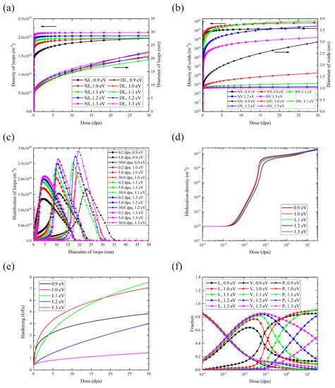
Figure 5.
Rate theory calculations with various migration energy of vacancy. (a) Number density and diameter of loops. (b) Number density and diameter of voids. (c) Distribution of loops at 0.2 dpa, 5 dpa and 30 dpa. (d) Dislocation density. (e) Hardening. (f) Contribution of loops (L), voids (V) and precipitates (P) to hardening.
The hardening is sensitive to , as shown in Figure 5e. We can find that with the increase of , hardening increases first and then decreases greatly, and the smallest hardening appears when . The fractions of microstructures’ contribution in Figure 5f demonstrate that the loops’ contribution becomes large while the void’s contribution becomes small with the increase of . In addition, the contribution of precipitates does not show a significant difference between different .
4. Discussion
4.1. Effects of Four Strengthening Methods to Microstructures
For fine grain strengthening, the simulation results show that the size of loops and voids are almost independent with grain size. In fact, it correlates with grain boundaries and experimental results have revealed complex effects of grain boundaries on defects. Some references reported that irradiation could result in a depleted defect zone near grain boundaries, which was ascribed to the absorption of defects by the boundary [20,21], while some other references reported that no depleted defect zone was observed [22,23]. Even though the grain boundary could affect the defects, the effect is much weaker than that induced by the surface [20]. It seems that the simulation results present are not at conflict with the reported experimental results.
The inhabitation of growth of dislocation loops has also been observed in steels with the addition of precipitates such as MX phase or ODS particles [24,25]. For instance, the saturated size of dislocation loops decreased from 54 nm to 21 nm in CLAM steel when the number density of MX phase increased by 60 times through the addition of Si into the steel [25]. Even the nucleation and growth of dislocation loops at the interfaces between the ODS particles and the matrix were directly observed [26]. In addition, the nanostructured ferritic alloys show great resistance to irradiation swelling [27]. The results of the experiment indicate that second phases may inhibit the growth of loops and voids, which qualitatively supports the simulation results in our model.
The four strengthening methods discussed in the above section can be divided into two classes, the one with enhancement of sink strength to point defects or mobile clusters (fine grain strengthening, dislocation strengthening and second phase strengthening), and the other one with impediment of migration of defects (solid solutions strengthening). We can find that the methods in first class almost have no effects on hardening, while the method in second class can greatly improve the hardening resistance of bcc iron-based alloy. The study of strengthening mechanisms is closely related to the evolution of microstructures.
The strengthening methods in first class can promote the increase of number density of loops, and inhibit the growth of loops slightly. Meanwhile, the number density of voids decreases with the enhancement of sink strengths and the size of voids has very little change. To reveal the mechanisms of these observations, the equilibrium concentrations of point defects are discussed. For simplicity, the clustering in cascade and the thermal equilibrium concentration of vacancy are neglected, then the balanced equations can be written as
where is the recombination constant for interstitial and vacancy. and are total sink strengths for interstitials and vacancies respectively. Considering the strengthening of sinks in this model, the term of recombination is far smaller than absorption by sinks. Therefore, the recombination of defects can be omitted approximately. Thus, for steady-state conditions, the concentration of interstitials and vacancies can be obtained analytically as following expressions:
Then the growth rate of dislocation loop and void can be given as
In fact, and decrease with the increase of sink strength, but can considered as independent with sink strength. Therefore, the size of voids almost has no change when the sink strength varies. However, the growth rate of loops is changed, with the expression given as
In this study, the dislocation loop would absorb interstitials preferentially, which indicates that is positive. is not changed with the increase of sink strength, while decreases. Therefore, the growth of loops is inhibited by sink strengthening.
For strengthening methods in the second class, the growth of voids is greatly limited with the increase of . This can be easily understood due to the harder aggregation of vacancies caused by higher value. In addition, the growth rate of loops can be expressed as a function of [5]:
where is a constant. We can find that the increase of can lead to the decrease of growth rate of loops, which can also be observed in Figure 5a. However, the effect of factor to growth rate of loops is small because and the limited range of . Therefore, the change of loops caused by different is less distinct than that of voids. Considering the number density of voids simultaneously, the effects of on voids is far more significant than that on loops at high dose.
Recently, we have performed ion irradiation experiment study on bcc FeCrAl alloys. Figure 6 shows the size and number density of dislocation loops in bcc Fe-12Cr-xAl (x = 0, 2, 4, 6) irradiated to peak dose of 1dpa at 330 °C with argon ions. The experimental data were obtained with transmission electron microscopy. It can be seen that size of dislocation loops is between 7–15 nm, and the number density is between 2–5 × 10²²/m3 (Detailed research results will be published elsewhere). With the increase of Al content (which means the increase of migration energy of defects), the loop size decreased and number density increased. The experimental results are consistent with the simulation results.
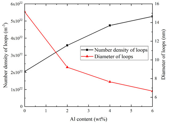
Figure 6.
Number density and diameter of dislocation loops in bcc Fe-12Cr-xAl (x = 0,2,4,6) irradiated to peak dose of 1dpa at 330 °C with argon ions.
4.2. The Selection of Strengthening Method
Through the above simulations, the response of hardening to four strengthening methods can be observed. For fine grain strengthening and dislocation strengthening, the irradiation hardening is almost kept unchanged when changing grain size and initial dislocation density. For second phase strengthening, the irradiation hardening can be inhibited to some extent by mainly increasing the number density of precipitates. Only the solid solutions strengthening can have significant effects on irradiation hardening. Therefore, the simulations suggest that the solid solutions strengthening should be the most proper method to inhibit irradiation hardening of bcc iron-based alloy. At a high dose, the irradiation induced hardening mainly comes from the contribution of voids. In fact, solid solutions strengthening can effectively inhibit the nucleation and growth of voids, which improves the hardening resistance of bcc iron-based alloy.
In the present study, neutron irradiation induced defects and their effects on hardness are simulated. It should be noticed that ion irradiations have been widely used to simulate neutron irradiations due to its various advantages, and micro- to nano-scale testing techniques have been employed to evaluate the mechanical properties of miniature ion irradiated specimens fabricated with focusing ion beam (FIB) methods as recently reviewed by J. Ast et al. [28] (Further discussions on ion irradiations and corresponding miniature specimen testing are beyond the scope of present study). These techniques provide supplementary tools for neutron irradiation and conventional mechanical testing methods used for neutron-irradiated bulk materials that are practically employed in nuclear engineering.
The limitations of the model used in present study should be mentioned. Widely used Fokker-Planck method was employed to resolve the rate theory equations, thus only small interstitial (1, 2, 3 SIAs) and vacancy clusters (1, 2, 3, 4 vacancies) are considered mobile under Fokker-Planck approximation, as reported in many literatures. Actually, larger clusters such as dislocation loops may also has some weak mobility, thus neglect of such mobility may result in some discrepancy. To include the mobility of large defect clusters, grouping method or even complete discrete rate equations is a possible way. However, other problems such as the lack of accurate rate coefficients between large clusters and other clusters and low calculation efficiency exist in these methods.
5. Conclusions
In the present study, four typical strengthening methods including fine grain strengthening, dislocation strengthening, second phase strengthening and solid solutions strengthening are simulated with rate theory to investigate the effects of strengthening methods on the defect evolution. The main conclusions can be drawn as:
- (i)
- Strengthening methods with the enhancement of sink strength (fine grain strengthening, dislocation strengthening and second phase strengthening) have little effects on the evolution of voids, while strengthening method with impediment of migration of defects (solid solutions strengthening) can effectively inhibit the nucleation and growth of voids.
- (ii)
- At a high dose, the contribution of voids dominates the factors that affect irradiation hardening.
- (iii)
- The solid solutions strengthening is the most proper method to inhibit irradiation hardening of bcc iron-based alloy for the restraints to voids.
Author Contributions
Conceptualization, L.G.; data curation, C.C. and Y.L.; formal analysis, C.C. and Z.X.; methodology, L.G. and Y.W.; software, C.C.; supervision, L.G.
Funding
This research was funded by National Natural Science Foundation of China (11775162 and U1532134) and the International Science & Technology Cooperation Program of China (2015DFR60370).
Acknowledgments
The financial supports from the National Natural Science Foundation of China (11775162 and U1532134) and the International Science & Technology Cooperation Program of China (2015DFR60370) are gratefully acknowledged. RADAFP developed by our team could be authorized to users for use under proper conditions after detailed discussions. The numerical calculations in this paper have been done on the supercomputing system in the Supercomputing Center of Wuhan University.
Conflicts of Interest
The authors declare no conflict of interest.
References
- Gelles, D.; Thomas, L.; Davis, J.; Michel, D. Ferritic alloys for use in nuclear energy technologies. In Proceedings of the TMS AIME, Warrendale, PA, USA, 1984; p. 559. [Google Scholar]
- Yu, Y. Rate Theory Study on Irradiation-Induced Dislocation Loops in Reduced Activation Martensitic Steels and Austenitic Steels; Wuhan University: Wuhan, China, 2016. [Google Scholar]
- Maziasz, P.; Klueh, R. ASTM-STP-1046; American Society for Testing and Materials: West Conshohocken, PA, USA, 1989; p. 35. [Google Scholar]
- Was, G.S. Fundamentals of Radiation Materials Science; Springer: Berlin, Germany, 2007. [Google Scholar]
- Hashimoto, N.; Tanimoto, J.; Kubota, T.; Kinoshita, H.; Ohnuki, S. Analysis of helium and hydrogen effect on RAFS by means of multi-beam electron microscope. J. Nucl. Mater. 2013, 442, S796–S799. [Google Scholar] [CrossRef]
- Duparc, A.H.; Moingeon, C.; Smetniansky-de-Grande, N.; Barbu, A. Microstructure modelling of ferritic alloys under high flux 1 MeV electron irradiations. J. Nucl. Mater. 2002, 302, 143–155. [Google Scholar] [CrossRef]
- Meslin, E.; Barbu, A.; Boulanger, L.; Radiguet, R.; Pareige, P.; Arakawa, K.; Fu, C.C. Cluster-dynamics modelling of defects in a-iron under cascade damage conditions. J. Nucl. Mater. 2008, 382, 190–196. [Google Scholar] [CrossRef]
- Jourdan, T.; Bencteux, G.; Adjanor, G. Efficient simulation of kinetics of radiation induced defects: A cluster dynamics approach. J. Nucl. Mater. 2014, 444, 298–313. [Google Scholar] [CrossRef]
- Jourdan, T.; Stoltz, G.; Legoll, F.; Monasseb, L. An accurate scheme to solve cluster dynamics equations using a Fokker–Planck approach. Comput. Phys. Commun. 2016, 207, 170–178. [Google Scholar] [CrossRef]
- Xu, D.; Hu, X.; Wirth, B.D. A phase-cut method for multi-species kinetics: Sample application to nanoscale defect cluster evolution in alpha iron following helium ion implantation. Appl. Phys. Lett. 2013, 102, 011904. [Google Scholar] [CrossRef]
- Watanabe, Y.; Morishita, K.; Nakasuji, T.; Ando, M.; Tanigawa, H. Helium effects on microstructural change in RAFM steel under irradiation: Reaction rate theory modeling. Nucl. Instrum. Methods Phys. Res. B 2015, 352, 115–120. [Google Scholar] [CrossRef]
- Kohnert, A.A.; Wirth, B.D.; Capolungo, L. Modeling microstructural evolution in irradiated materials with cluster dynamics methods: A review. Comput. Mater. Sci. 2018, 149, 442–459. [Google Scholar] [CrossRef]
- Christien, F.; Barbu, A. Effect of self-interstitial diffusion anisotropy in electron-irradiated zirconium: A cluster dynamics modeling. J. Nucl. Mater. 2005, 346, 272–281. [Google Scholar] [CrossRef]
- Soneda, N.; de la Rubia, T.D. Defect production, annealing kinetics and damage evolution in α-Fe: An atomic-scale computer simulation. Philos. Mag. A 1998, 78, 995. [Google Scholar] [CrossRef]
- Wolfer, W.G.; Glasgow, B.B. Dislocation evolution in metals during irradiation. Acta Met. 1985, 33, 1997–2004. [Google Scholar] [CrossRef]
- Jourdan, T. Influence of dislocation and dislocation loop biases on microstructures simulated by rate equation cluster dynamics. J. Nucl. Mater. 2015, 467, 286–301. [Google Scholar] [CrossRef]
- Mayoral, M.H.; Briceño, D.G. PERFECT Project, Advance Report, Deliverable P26. Task II-3-2; Interreg Europe: Lille, France, 2008. [Google Scholar]
- Gao, J.; Yabuuchi, K.; Kimura, A. Ion-irradiation hardening and microstructural evolution in F82H and ferritic alloys. J. Nucl. Mater. 2019, 515, 294–302. [Google Scholar] [CrossRef]
- Lu, Z.; Faulkner, R.G.; Sakaguchi, N.; Kinoshita, H.; Takahashi, H.; Flewitt, P.E.J. Effect of hafnium on radiation-induced inter-granular segregation in ferritic steel. J. Nucl. Mater. 2006, 351, 155–161. [Google Scholar] [CrossRef]
- Li, M.; Kirk, M.A.; Baldo, P.M.; Xu, D.; Wirth, D.B. Study of defect evolution by TEM with in situ ion irradiation and coordinated modeling. Philos. Mag. 2012, 92, 2048–2078. [Google Scholar] [CrossRef]
- Sakaguchi, N.; Watanabe, S.; Takahashi, H. Heterogeneous dislocation formation and solute redistribution near grain boundaries in austenitic stainless steel under electron irradiation. Acta Mater. 2001, 49, 1129–1137. [Google Scholar] [CrossRef]
- Kano, F.; Fukuya, K.; Hamada, S.; Miwa, Y. Effect of carbon and nitrogen on grain boundary segregation in irradiated stainless steels. J. Nucl. Mater. 1998, 258, 1713–1717. [Google Scholar] [CrossRef]
- Guo, L.; Luo, F.; Yu, Y. Dislocation loops in Irradiated Nuclear Materials; National Defense Industry Press: Beijing, China, 2017. [Google Scholar]
- Kobyashi, S.; Tsuruoka, Y.; Nakai, K.; Kurishita, H. Effect of neutron irradiation on the microstructure and hardness in particle dispersed ultra-fine grained V–Y alloys. J. Nucl. Mater. 2004, 329, 447–451. [Google Scholar] [CrossRef]
- Zhao, M.; Liu, P.; Bai, J.; Zhu, Y.; Wan, F.; Ohnuki, S.; Zhan, Q. In-situ observation of the effect of the precipitate/matrix interface on the evolution of dislocation structures in CLAM steel during irradiation. Fusion Eng. Des. 2014, 89, 2759–2765. [Google Scholar] [CrossRef]
- Oka, H.; Watanabe, M.; Kinoshita, H.; Shibayama, T.; Hashimoto, N.; Ohnuki, S.; Yamashita, S.; Ohtsuka, S. In situ observation of damage structure in ODS austenitic steel during electron irradiation. J. Nucl. Mater. 2011, 417, 279–282. [Google Scholar] [CrossRef]
- Odette, G.R.; Alinger, M.J.; Wirth, B.D. Recent developments in irradiation-resistant steels. Annu. Rev. Mater. Res. 2008, 38, 471–503. [Google Scholar] [CrossRef]
- Ast, J.; Ghidelli, M.; Durst, K.; Göken, M.; Sebastiani, M.; Korsunsky, A.M. A review of experimental approaches to fracture toughness evaluation at the micro-scale. Mater. Des. 2019, 173, 107762. [Google Scholar] [CrossRef]


© 2019 by the authors. Licensee MDPI, Basel, Switzerland. This article is an open access article distributed under the terms and conditions of the Creative Commons Attribution (CC BY) license (http://creativecommons.org/licenses/by/4.0/).