Abstract
In the pipe manufacturing and pipe processing industry, the demand for cost-effective pipes with high strength and good ductility is increasing. In the present study, the inductive longitudinal welding process was combined with a Quenching and Partitioning (Q&P) treatment to manufacture pipes with enhanced mechanical properties. The aim of the Q&P process is to establish a martensitic structure with increased retained austenite content. This allows for the beneficial use of both phases: the strength of martensite as well as the ductility of retained austenite. A 42SiCr steel, developed for Q&P processes, was joined at the longitudinal seam by a high-frequency induction (HFI) welding process and was subsequently heat-treated. The applied heat treatments included normalizing, austenitizing, quenching, and two Q&P strategies (Q&P-A/Q&P-B) with distinct quenching (Tq = 200/150 °C) and partitioning temperatures (Tp = 300/250 °C). Investigations of the microstructures revealed that Q&P tubes exhibit increased amounts of retained austenite in the martensitic matrix. Differences between the weld junction and the base material occurred, especially regarding the morphology of the martensite; the martensite found in the weld junction is finer and corresponds more to the lath-type morphology, compared to the base material in the circumference. In all zones of the welded tube circumference, retained austenite has been found in similar distributions. The mechanical testing of the individual tubes demonstrated that the Q&P treatments offer increased strength compared to all other states and significantly improved ductility compared to the quenched condition. Therefore, the approach of Q&P treatment of HFI-welded tubes represents a route for the mass production of high-strength tubular products with improved ductility.
1. Introduction
1.1. Industrial Relevance
Since Speer et al. first reported the partitioning of carbon from supersaturated quenched martensite into retained austenite in 2003 [1], quenching and partitioning (Q&P) has been widely investigated in terms of mechanisms, materials, routes, and processing. Due to their combination of high strength and ductility, Q&P steels have even been proposed to represent the third-generation advanced high-strength steels (AHSS) for the automotive sector [2,3]. Sixteen years after Q&P processing was developed, material for processing is now commercially available. However, a widespread industrial use has not yet been realized. In the year 2016, 1.6 billion tons of steel have been produced, of which 139 million t and thus ~9% were further processed to tubular products [4,5]. Therefore, tubes represent the most important semi-finished product in terms of steel production. The proportion of longitudinally welded steel pipes in this year was 71% [5] and is further increasing [6]. High-frequency induction (HFI) welding is the most common welding process to produce steel pipes. Clearly, there is a need to further investigate HFI-welding and its effects on subsequent Q&P heat treatments and the resulting mechanical properties of steel tubes.
1.2. Scientific Fundamentals
In Q&P processes, low-alloyed hypo-eutectoid steels are exposed to three subsequent heat treatment steps. At first, the material is heated above austenitization temperature to transform its initial, typically ferritic-pearlitic microstructure into austenite and to dissolve precipitates. The subsequent quenching step to a temperature Tq between the martensite start Ms and the martensite finish Mf temperature leads to the formation of a proportion of martensite that is supersaturated with carbon. The cooling process is interrupted above Mf to suppress a complete transformation into martensite, so that a certain volume fraction of austenite remains. After quenching in step 3, the soaking temperature Tp between Ms and Mf or slightly above Ms allows the partitioning, i.e., the isothermal diffusion of carbon from martensite into the adjacent untransformed austenite. The carbon atoms stabilize the austenitic phase, resulting in highly carbon-enriched retained austenite after subsequent cooling to room temperature. The amount of retained austenite, which plays a key role in determining the resulting mechanical properties [7], is controlled by the quenching temperature below Ms. Its stability increases with the degree of carbon saturation [7]. An important aspect of the heat treatment is to suppress the transformation of carbon-enriched areas to carbides instead of stabilizing austenite. This is achieved with the help of an adequate alloy composition. Carbon increases the hardness and is necessary to stabilize the austenite. It also increases the hardness of the material by contributing to the formation of martensite. For welding processes, the carbon content is therefore usually limited. Silicon prevents the precipitation of cementite and increases the carbon content in austenite respectively. The high oxidation affinity of silicon requires the molten material to be expelled during the HFI-welding processes. As an alloy component, chromium delays the bainitic and pearlitic transformation, lowers the Ms temperature [8,9], and increases hardenability, and thus strength. Manganese reduces the critical cooling rate for the formation of martensite and increases the gamma filed (austenite stabilizer) [7]. Due to its high oxidation affinity, manganese also has a significant influence on welding processes.
The use of 42SiCr (Table 1) for Q&P processing was first published by Cerny et al. in 2011 [10], who reported on achieving a tensile strength of up to 1965 MPa at an ultimate strain at 5 mm initial gauge length of up to A5mm = 21%. According to Jirková et al., a retained austenite content of up to about 13% can be obtained by suitable Q&P heat treatment of 42SiCr, which leads to ultimate strains of more than 20%. Compared to common Q&P steels, 42SiCr is characterized by relatively high carbon and chromium contents. To ensure good weldability, common steels for Q&P processing usually contain only up to 0.3 wt. % carbon. Due to the risk of internal stresses and the absence of filler materials, pressure-welding processes, such as HFI-welding of steels, are usually performed with grades of up to 0.24 wt. % carbon. For pipeline transportation systems, the carbon content in ISO 3183 is limited to 0.23 wt. % and the carbon equivalents (CE) to CEIIW = 0.43%, according to the International Institute of Welding and CEPcm = 0.25% in reference to the Japanese Welding Engineering Society. This limits the steel grades to L555Q or X80Q and therefore, yield strengths and ultimate tensile strengths of pipeline steels to Rt0,5 = 705 MPa and Rm = 825 MPa. With a carbon content of 0.42 wt. % as well as carbon equivalents of CEIIW = 0.82 and CEPcm = 0.60, 42SiCr the material is expected to exhibit poor weldability when simply taking the carbon content and CE into account. In longitudinal HFI-welding processes, the electric energy of an alternating current in a working coil creates an electromagnetic field that induces a current in an open tubular geometry by electromagnetic induction. The current causes heat generation by means of Joule heat. The heat distribution is mainly controlled by the current distribution. Magnetic losses contribute to further heating. The current distribution is mainly determined by the skin effect and the proximity effect that lead to a local heating of the contact surfaces and strip edges. The melt is expelled from the pool towards the circumference and in longitudinal direction by Lorentz forces. Compression is usually provided by a set of squeeze rolls. This causes the molten material to be completely squeezed out of the contact area and to form the weld bead. Subsequent cooling of the joining area occurs mainly by heat conduction to the circumference, causing thermal stresses and possibly the formation of brittle phases. Subsequent normalizing of either the joining area or of the complete pipe cross-section is used to remove these microstructural changes. According to their thermomechanical history, the joining areas in HF-welds are comprised of the weld bead (molten material), the weld junction with the fusion line (partially molten), the coarse-grained (grain growth due to heating in γ-region) and fine-grained heat-affected zone (recrystallizing in γ-region), as well as the thermomechanically-affected zone (grain deformation, intercritical annealing, tempering). Usual weld defects comprise cold weld and penetrator [11] that occur due to low or high welding power, oxide formation, the presence of inclusions or voids in the joint, and brittle microstructures.

Table 1.
Chemical composition of investigated alloy 42SiCr.
2. Materials and Methods
2.1. Material and Tube Sample Preparation
The material used in this study is a hot rolled 42SiCr steel sheet with a thickness of 1.8 mm, exhibiting a normalized microstructure of ferrite and cementite (non-lamellar pearlite, Figure 1). The chemical composition, as measured by optical emission spectroscopy (OES) with a Q4 Tasman apparatus (Bruker, Billerica, MA, US), is shown in Table 1. The most relevant alloying elements are silicon, chromium, and manganese.
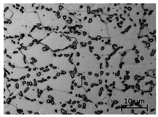
Figure 1.
Initial microstructure of 42SiCr base material, optical microscopy.
A thermophysical calculation of the phase transformations during heating and cooling was performed using JMatPro® V7.0 (Sente Software, Guildford, UK). As illustrated in the time-temperature-austenitization (TTA) diagram (Figure 2a) the austenitization temperature strongly depends on the heating rate. It needs to be taken into account that the precipitations have to be completely dissolved in austenite to obtain a homogeneous distribution of carbon and the alloying elements within the steel matrix during austenitization. As shown in the continuous cooling transformation (CCT) diagram (Figure 2b), the martensitic transformation starts at T = 294 °C, 90% of the transformation is completed at 173 °C. The thermal history of all treatments performed is also shown in (Figure 2b) to illustrate that the critical cooling rate for martensitic transformation is reached in any case.
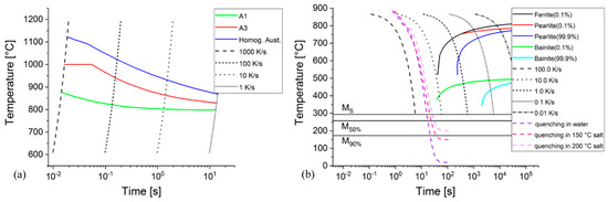
Figure 2.
(a) Time-temperature-austenitization (TTA) and (b) continuous cooling transformation (CCT) diagrams, calculated using JMatPro.
2.2. Longitudinal Tube Welding
For the longitudinal HFI-welding operations, an experimental pipe welding rig of Chemnitz University of Technology (Figure 3) was used with tube specimens of Ø 60 mm × 1.9 mm. The specimens were prepared from bent 42SiCr-segments with a length of 170 mm. As the HFI-pipe welding process requires an acceleration to a defined feed rate and braking phases, the 42SiCr-segments were attached to sacrificial pipe segments of low carbon steel by TIG butt-welding. The joint was subsequently polished and cleaned (Figure 3). Temperature measurements were performed using an VarioCAM® inspect hr 680 thermal camera (InfraTec, Dresden, Germany) and Type K thermocouples in a 90° and 180° position to the weld seam. The upsetting force at the squeeze-roll-stand was measured by a 9051A load washer (Kistler, Winterthur, Switzerland). As a finding of prior investigations on welding process optimization, longitudinal welding was performed at a feed speed of 8 m/min at a current frequency of f = 220 kHz and an electric power of Pel = 49 kW. The entry angle was set to 2.5° and the upsetting force was Fc = 12.5 kN. A water-cooled ferrite core (Ø 42 mm × 200 mm) was positioned axially with its end at the level of the weld point.
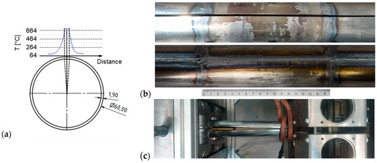
Figure 3.
Sample geometry and temperature profile on the tube surface (a), prepared sample (top) and welded sample (bottom) with 42SiCr specimens in the middle and sacrificial segments on the left and right (b), welding setup (c).
The welds were inspected visually and by computer tomography (CT) using a V|TOME|X S 240 micro CT scanner (GE Healthcare, Phoenix, AZ, USA). In the obtained weld, voids were found only in the unequally distributed weld excess (Figure 4). The cross section and particularly the fusion line are consistent and do not contain macroscopic voids or inclusions.
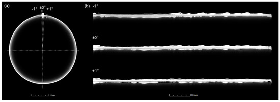
Figure 4.
Computer Tomography (CT) scan of the welded tube with (a) front view on weld seam and (b) longitudinal view on weld seam.
2.3. Post-Welding Heat Treatment
The HFI welding process was followed by different heat treatments to investigate the influence on the microstructure and mechanical properties. Compared to the as-welded state, the pipe elements were normalized in the first case. This complies with conventional heat treatment for industrial pipes. After austenitization at 920 °C for 20 min in a LM512 laboratory furnace (Linn High Therm, Hirschbach, Germany), the material was slowly chilled to room temperature in the furnace. The second heat treatment focuses on a fully martensitic microstructure with a suppression of retained austenite by rapid cooling to room temperature. The material was austenized at 950 °C for 6 min in the furnace and then water-quenched to room temperature. The heat treatment, which implements Q&P, was performed according to prior investigations by Masek et al. [7,8,10] and lead to different austenitization temperatures for normalizing, quenching, and Q&P. After austenitization and soaking time, which results in a homogeneous microstructure (according to the TTA diagram in Figure 2a), the pipe section was transferred to a preheated NaCl salt bath. With 200 °C (Q&P-A) and 150 °C (Q&P-B), two distinct temperatures were chosen for the salt bath. The necessary cooling rate for a fully martensitic transformation was obtained according to the CCT diagram of Figure 2b. In the following step, the material was transferred to a second laboratory furnace N60/85SHA (Nabertherm, Lilienthal, Germany), with a temperature of 300 °C (Q&P-A) and 250 °C (Q&P-B), to perform the partitioning process. Both furnaces were controlled within a temperature range of ±5 K. Cooling to room temperature took place in air. Considering the calculated CCT diagrams and the simulated cooling rates (Figure 2b), the critical cooling rate to obtain a fully martensitic structure was achieved by quenching and the Q&P routes. The performed heat treatments for pipe elements are shown schematically in Figure 5, corresponding values of relevant temperatures are given in Table 2.
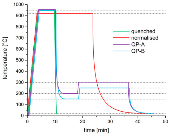
Figure 5.
Thermal history sketch of the different heat treatments performed in this study.
Table 2.
Routes and characteristic temperatures for processing and different heat treatments.
2.4. Microstructural Analysis and Mechanical Testing
The heat-treated pipe samples were cut perpendicular to the rolling direction into ring-shaped cross-sections to examine the microstructure at distinct locations on the circumference. For microstructural analysis, the samples had been polished and etched for 20 s with 3% Nital solution. The microstructural analysis was carried out using an optical microscope Zeiss Axio Vert.A1 MAT and a LEO VP 1455 SEM (Carl Zeiss, Oberkochen, Germany). The phase composition and distribution of alloying elements were analyzed using an Xflash4010 EDX (Bruker, Billerica, MA, USA). Electron backscatter diffraction (EBSD) measurements of distinctive microstructure areas were carried out on samples vibropolished by MasterMet 2 (Illinois Tool Works, Lake Bluff, IL, USA) colloidal silica suspension using a Nordlys F detector (Oxford Instruments, Abingdon, UK) and a primary energy of 20 keV. A step size of 0.08 µm was used. Thereby, the local structure, morphology, and phase distribution could be determined. Mechanical testing was performed by means of Vickers hardness measurement HV1 and HV3 at the pipe cross-section according to DIN EN ISO 3183 [12] for HFI-welded pipes. The tests were carried out by an M1C 010 (EMCO-TEST Prüfmaschinen, Kuchl, Austria) hardness measuring device. Tensile tests were performed according to DIN EN ISO 6892-1 [13] and DIN EN ISO 3183 [12] with pipe sections. Specimens with a length of the parallel reduced section of the test piece of Lc = 30 mm were extracted by water jet cutting. The sample geometry (Figure 6) follows ISO 6892-1. For the tensile tests, an Inspekt 150 (Hegewald and Peschke, Nossen, Germany) universal testing machine was used.
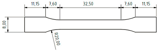
Figure 6.
Specimen geometry used for tensile testing [mm].
Tube-flattening tests were performed in accordance to ISO 8492 [14], using tube sections of 10 mm length, with the weld positioned at 90° to the direction of the traverse movement. All tensile and tube-flattening tests were carried out 3 times for each parameter set to achieve substantiated statistics.
3. Results
3.1. Microstructure and Hardness
Due to the heat influx during induction heating, welding, and subsequent cooling, the pipe cross-section is subject to a process and material-specific, time- and position-dependent heat distribution which locally affects microstructural evolution. Therefore, the microstructures of distinct zones along the neutral axis were analyzed in different regions, representing the weld junction, the coarse- and fine-grained heat affected zone (CGHAZ, FGHAZ), and the base material. The positions and sizes of these zones in relation to the joining zone were determined by thermal imaging (Figure 3), optical microscopy (Figure 7), and hardness measurements (Figure 8).
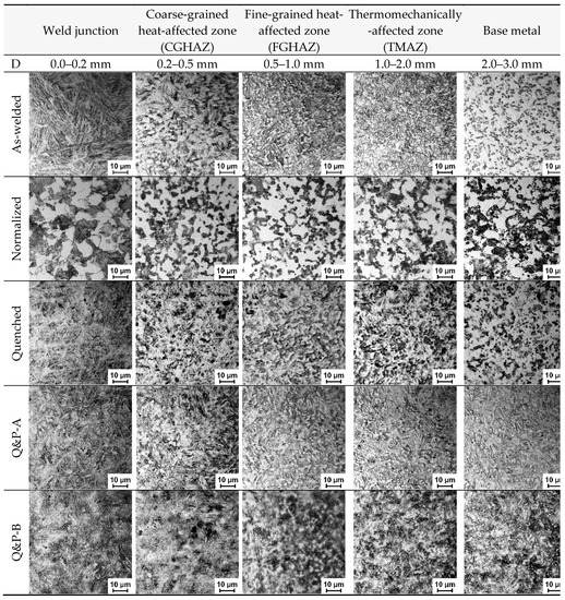
Figure 7.
Optical micrographs of different 42SiCr samples after HFI welding and heat treatment at different distances (D) along the neutral axis from the joint.
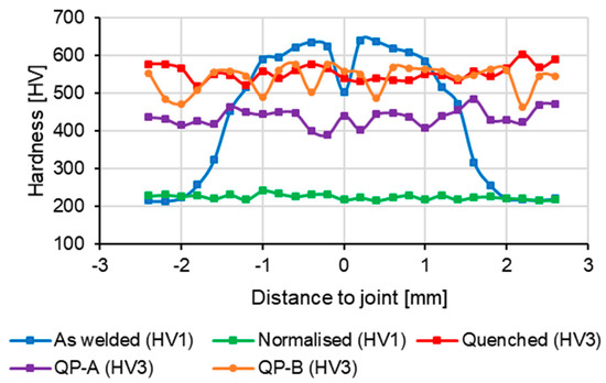
Figure 8.
Hardness distributions of HFI welded 42SiCr pipes across the weld for the different material conditions of this study.
It should be noted that the hardness values of both Q&P treatments locally fluctuate by up to 100 HV, whereas the hardness of the quenched state deviates significantly less along the circumference. The joining area is especially affected by this variation. This can be explained by the multi-phase microstructure of martensitic areas with retained austenite between martensite laths and triple points. The following discussion considers the different material states, obtained by the distinct heat treatments after welding, in greater detail.
3.1.1. As-Welded Pipes
The base material of the as-welded pipes encompasses the areas more than 2 mm apart from the bond line and represents the initial microstructure. As shown in Figure 9a, the base material contains spherical orthorhombic M3C carbides in a ferritic matrix. In the fine-grained mixed microstructure of the thermomechanically-affected zone (TMAZ), the hardness increases from 220 HV to 580 HV. The adjacent heat-affected zone (HAZ) comprises coarse, plate-like martensite and spherical retained austenite, detected by EBSD analyses (exemplarily shown by an inset in Figure 9c). Blurred islands (Figure 9b and c) in the HAZ were identified as retained austenite. The martensite contributes to the elevated hardness level between 508 HV to 640 HV in the HAZ. Due to the skin- and proximity-effect in HFI-welding, as well as the conduction of heat in the pipe circumference, the transformation temperatures in the HAZ are lower than in the weld junction (Figure 3). Therefore, lattice stresses cannot be decreased by slip and recovery processes. This causes the development of coarse plate-shaped martensite (Figure 7, Figure 9c). However, fine lath-like martensite is formed in the weld junction (Figure 7, Figure 9d). The appearance of the lath martensite in the weld junction suggests that the transformation temperature is higher than that of plate martensite [15]. At higher phase transformation temperatures, internal stresses are lowered by dynamic softening. This mechanism reduces residual stresses associated with the martensitic transformation and softens the martensite which leads to a reduced hardness of ~500 HV in the weld junction compared to the adjacent HAZ. The high temperature level may also lead to oxidation and thus to a reduction of the carbon content, resulting in a higher martensite phase transformation temperature for the weld junction and the formation of lath martensite. The determination of the equivalent grain diameter by the EBSD orientation maps using a misorientation greater than 10°, revealed an average grain diameter of 9.5 µm for the ferritic phase of the base material, 2.5 µm for the martensitic phase of the HAZ, and 2.7 µm for the martensitic phase of the weld junction. Due to the significant reduction of the grain size, a recrystallization can be concluded both in the HAZ and in the weld junction. In the weld junction, retained austenite could not be determined (EBSD phase map inset in Figure 9d) in the weld. As no pronounced fusion line can be observed, it can be assumed that were-formed oxides have been expelled from the weld junction to the weld-seam.
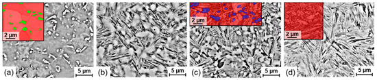
Figure 9.
Scanning Electron Microscopy (SEM) micrographs of the base material (a), FGHAZ (b), CGHAZ (c), and weld junction (d) in as-welded condition, inserts show the results of EBSD analyses with orthorhombic M3C (green), bcc ferritic/martensitic (red) and fcc austenitic (blue) crystal structure and microstructure.
3.1.2. Normalized Pipes
The normalized tubes (Figure 7) show the bcc structure of ferrite and pearlite over the whole cross-section. Accordingly, the measured hardness is almost constant at ~220 HV over the entire sample (Figure 10). The pearlite appears typically as a lamellar structure. In the base material, carbides precipitates in spherical shapes can still be observed (Figure 10a).
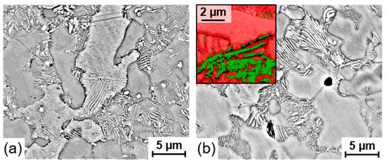
Figure 10.
SEM micrographs of the base material (a) and the weld junction (b) in normalized condition, inset shows results of EBSD analysis with orthorhombic M3C (green) and bcc ferrite (red) crystal structure and microstructure.
3.1.3. Quenched Pipes
Samples that were austenitized and quenched after longitudinal welding (Figure 7) show a martensitic structure and carbides over the entire circumference. Consequently, the hardness varies in a close range of 519 to 602 HV3. The martensite grows as fine crystallites and carbides were less pronounced in the weld junction compared to other regions.
3.1.4. Q&P-A Heat-Treated Pipes
Corresponding to prior investigations [7,8,10], Q&P-A-treated samples (Figure 7) comprise martensite and retained austenite in all regions. This was confirmed by the SEM micrographs and EBSD phase maps in Figure 11. The average hardness of 436 HV3, obtained by Q&P-A, is 21% lower than in the quenched state. This can be attributed to the reduced carbon content in the martensite due to the diffusion of carbon into the retained austenite during post-weld partitioning. The results of the EBSD measurements show that the retained austenite occurs from the base material to the weld junction. It appears at triple points of martensitic grains as well as between martensitic laths (see inserts in Figure 11a,b). The significant similarity in the distribution of retained austenite in the microstructure of base material and weld junction indicates a homogenization of the microstructure as a result of the Q&P heat treatment. The martensite laths, however, are clearly pronounced at the weld seam. This corresponds to the observations with the quenched pipe samples.
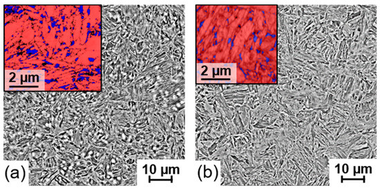
Figure 11.
SEM micrographs of Q&P-A samples base material (a) and weld junction (b), inserts show results of EBSD analyses with bcc/martensite (red) and fcc austenite (blue) crystal structure and microstructure.
3.1.5. Q&P-B Heat-Treated Pipes
In terms of the general morphology and formation of the martensitic microstructure, Q&P-B samples (Figure 7) are similar to Q&P-A. However, the hardness values (average hardness Q&P-B: 538 HV3) are significantly higher than in Q&P-A, exceeding even those of the quenched state. The retained austenite content is much less apparent in Q&P-B than in Q&P-A. This is caused by the quenching temperature, which is 50 K lower in the Q&P-B than in the Q&P-A route. Therefore, a higher proportion of martensite is present during the partitioning process, which is also slower due to the lower temperature level. Hence, the carbon diffuses locally and retained austenite separates in thin bands between the martensitic laths. It is therefore more difficult to detect by SEM and EBSD (Figure 12). For the EBSD measurements on Q&P-B samples, the chosen step size of 0.08 µm was too large to detect the retained austenite. Investigations by Masek et al. [8,10,16] have confirmed the presence of retained austenite by means of transmission electron microscopy (TEM), but further work is required for a more quantitative analysis. As with Q&P-A treated samples, fine martensitic laths occur predominantly in the weld junction.
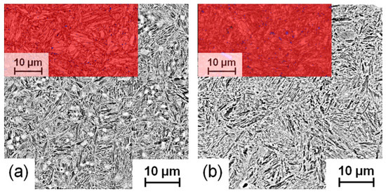
Figure 12.
SEM micrographs of Q&P-B samples base material (a) and weld junction (b).
3.2. Mechanical Properties
3.2.1. Tensile Testing
The tensile tests were performed according to ISO 6892-1:2016 [13] at a constant crosshead displacement rate of 0.05 mm/s. Yield strength Rp0.2, ultimate tensile strength Rm, and the ultimate strain A30mm were determined to analyze the effect of the welding as well as the heat treatment process on the resulting microstructures (Table 3).
Table 3.
Mechanical properties obtained by tensile testing.
As shown in Table 3 and Figure 13, the mechanical behavior depends strongly on the prior heat treatment. Whereas pipes in the as-welded state exhibit an excellent ductility with an ultimate strain of 27%, they offer a low tensile strength (Rp0.2 = 516 MPa; Rm = 672 MPa) which can be explained by the fully ferritic + Fe3C microstructure of the base material. A comparable stress–strain behavior is exhibited by the normalized state. With Rp0.2 = 770 MPa, the normalized samples exhibit a slightly higher yield stress but a reduced ultimate strain of 23%. Fully quenched (i.e., fully martensitic) specimens offer the lowest yield and tensile strength (Rp0.2 = Rm = 340 MPa) and an ultimate strain lower than 0.5%. The low measured strength can be attributed to a distinctive surface roughness in the parallel length, caused by sample preparation, which may be initiated cracks that led to early brittle failure. In contrast, Q&P-treated specimens exhibit a highly increased yield strength and tensile strength. With the Q&P-A-treated material, a tensile strength of 1670 MPa and an ultimate strain of 13% were obtained, whereas Q&P-B even increased the tensile strength to 1880 MPa at a slightly lowered ultimate strain of 10%. In comparison to the other heat treatment routes, Q&P steels tend to show increased scatter in terms of their mechanical properties (Figure 13). This underlines the strong influence of the heat treatment on the mechanical properties, and the need for careful control of the corresponding technological processes.
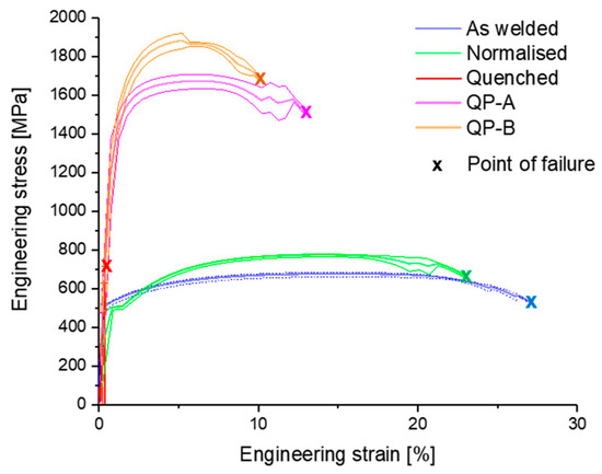
Figure 13.
Average, maximum and minimum stress–strain curve of tensile tests and point of failure for different heat treatments.
3.2.2. Tube-Flattening Tests
Tube-flattening tests were performed to obtain the strength and ductility of the welds and the pipe in total. Tube sections were compressed at a constant speed of 0.4 mm/s until cracking in the circumference occurred. The results are presented in Figure 14 as force-displacement (compression) curves. As the microstructures of the as-welded base material and the normalized pipes are mainly ferritic, the compression curves almost overlap to the point of failure of the as-welded samples. The failures occur in the as-welded samples in the HAZ, where the hardness is maximum. Nevertheless, with a compression of more than 2/3 of the diameter, the as-welded samples show a sufficient ductility and thus a good weldability of the 42SiCr with HFI-welding. The very high ductility exhibited by the normalized samples imply that a normalizing heat treatment of 42SiCr-welds is an efficient measure to mitigate undesired microstructural changes in steels suitable for Q&P-heat treatments. Comparing Q&P with quenched samples, a strong similarity of the steep curves is apparent. This can be attributed to the mainly martensitic microstructures. However, the quenched samples fail at much smaller compressions (6–8%). In contrast, the samples of both Q&P routes can bear compressions of about 36–38%. This complies with the higher ductility of the base materials documented in the tensile tests. The much-increased level of deformation to failure that was achieved with the Q&P samples, compared to the quenched samples, can be attributed to the positive effect of retained austenite. The tube-flattening tests thus revealed that the increased ductility also applies to the weld. As indicated by the higher hardness, Q&P-B tubes exhibit a slightly higher resistance to compression than the Q&P-A samples. This also corresponds with the higher strength of the Q&P-B samples determined during tensile testing.
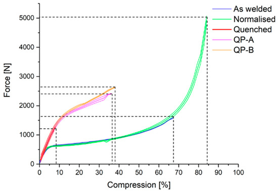
Figure 14.
Force-compression curves of tube flattening tests for different heat treatments.
4. Discussion
The HFI-welding process, in combination with subsequent post-welding heat treatments (normalizing heat treatment, quenching, and two different Q&P processes), was investigated experimentally on tubular 42SiCr steel with a thickness of 1.8 mm. The pipes were subjected to mechanical and metallographic inspection to evaluate the respective properties.
The weld junction and the surrounding areas are influenced thermally and mechanically (HAZ) during HFI-welding, the formerly ferritic microstructure in weld junction, CGHAZ, and FGHAZ undergoes a fully martensitic transformation. Considering a significantly smaller grain size of prior austenite before martensitic phase transformation in the weld junction and HAZ, compared to the base material, it can be assumed that temperatures and local deformation are sufficiently high in these regions for the occurrence of dynamic recrystallization. Also, the carbides, present in the initial material, are dissolved in the weld junction. Between the HAZ and the base material only few carbides remain. This was also observed by Wang for spot-welded Q&P 980 steel [17]. As described by Liu [18], the HAZ can be divided into three distinct zones: CGHAZ, FGHAZ, and TMAZ. Further observations by Liu [18] include that the maximum hardness occurs in the FGHAZ and very low amounts of retained austenite can be observed in the martensitic structure of the HAZ. These findings can also be confirmed by the present investigation. As stated by Mehner [19], the rapid cooling without holding phase prevents carbon diffusion into the austenite. Therefore, instead of retained austenite stabilized to room temperature, predominantly carbides can be found. A subsequent normalizing heat treatment leads to a ferritic-pearlitic microstructure in all regions and thus restores the ductility of the weld. The normalized state shows a uniformly distributed low hardness. A fully martensitic microstructure develops during quenching of 42SiCr. In contrast, during Q&P heat treatments, in all regions of the pipe cross-sections martensite is formed along with certain amounts of retained austenite, which can be located between martensite plates and at triple junctions. Also Yang [20] and Mehner [19] reported that retained austenite can be detected as interlath phase between the martensite laths. Due to the similarity of the microstructures, as well as the uniform distribution of retained austenite in the weld junction and the base material, it can be assumed that at least the Q&P-A heat treatment has contributed to a homogenization of the material and that the microstructural differences, caused by the HFI-welding process, have essentially been reduced. Differences between the pipe sections of Q&P heat-treated pipes exist in the form of a slightly finer martensitic microstructure in the weld junction.
In tensile tests, the as-welded state and the normalized material exhibit a high ductility but only low strength. The substantial influence of the heat treatment becomes obvious when comparing the quenched-only condition with the Q&P treatments, brittle failure occurs in quenched material. In contrast, the tensile strength of the Q&P-treated specimens is more than four times higher and the ultimate strain exceeds 10%. Corresponding to the investigations of De Moor [21], the effect of transformation-induced plasticity is most obvious here. According to his investigations, with an increase of the partitioning temperature and time, the fracture elongation could be significantly increased while the tensile strength and yield strength decreased slightly. The tube flattening test reflects the results of the tensile tests on the actual components: as with the tensile tests, the as-welded and the normalized states can endure the highest deformations. The specimens in the quenched-only state fracture in a brittle manner and show only a proportion of the ultimate strain compared to the Q&P-treated samples. The strength of quenched specimens is reduced by more than 50% relatively to Q&P-treated samples.
Despite the high carbon content and carbon equivalent, the weldability of 42SiCr by HFI-welding in terms of strength and ductility was thus also confirmed by the tube-flattening tests. It can be assumed that during longitudinal HFI-welding, the temporary heat input in combination with the high cooling rate during the solidification process leads to a limited precipitation of carbides. The metallographic investigations in the as-welded state showed only few carbides in the weld junction. It is also assumed, that the carbon atoms are dissolved in high-temperature austenite and remain dissolved in martensite due to diffusion-free transformation. As in all pressure welding processes, it is expected that a proportion of carbon of the weld junction is expelled to the weld seam during welding. Therefore, it is expected that the carbon content of the weld junction is reduced.
5. Conclusions
The welding tests in combination with an offline Q&P treatment have demonstrated that 42SiCr can be HFI-welded despite the high carbon equivalent and that a Q&P microstructure, comprising martensite and retained austenite, is formed throughout the welded tube. Thereby, the Q&P-A heat treatment provides higher ductility (A30mm = 13%) and Q&P treatment higher strength and hardness (Rm = 1880 MPa, average hardness: 538 HV3). The improved ductility of the Q&P-A can be attributed to the retained austenite at triple points of martensitic grains and between martensitic laths. In the Q&P-B route, the retained austenite is less pronounced and film-like. In samples treated with both Q&P routes, the martensite found in the weld junction was slightly finer and corresponded more to the lath-type morphology compared to the base material apart from the weld. In general, a clear homogenization of the microstructure after HFI-welding as a result of Q&P treatment is observed. In tube samples, the effect of the heat treatments on resistance to compression and maximum compression was tested. It was found, that Q&P pipes provide the highest resistance to compression in comparison to all other states with maximum compressions of >35%. Further metallurgical work (e.g., X-ray diffraction and transmission electron microscopy) is needed to fully determine and understand the microstructure and microstructural processes during optimized Q&P heat treatments in HFI-welds. However, the demonstrated properties of HFI-welded Q&P pipes offer a very large field of applications. For pipe and tube manufacturing, the processing parameters (e.g., feed speed, power, frequency, vee angle) and the material itself (e.g., composition, condition) require further optimization and mutual reconciliation. To enable carbon atoms to effectively stabilize the retained austenite, alloying elements need to be adjusted to suppress carbide formation completely. Furthermore, the material composition needs to comply with industrial regulations (i.e., in terms of carbon content and CE). Therefore, the replacement of a portion of carbon by austenite forming alloying elements should be considered. For the industrial processing of Q&P pipes, a completely continuous production, comprising forming, longitudinal welding, and inline heat treatment, is desired. An inline heat treatment would require the shortening of austenitization and partitioning periods. Further improvements in terms of ductility are required for the use of 42SiCr in tubes and pipes in transportation or construction. Also, fracture toughness is pivotal for future applications, and detailed investigations on the fracture behavior of HFI-welded Q&P pipes are recommended.
Author Contributions
Conceptualization, investigation, validation and writing—original draft preparation, P.B. and M.K.; investigation and writing—original draft preparation, J.Z.; supervision, administration, conceptualization, V.K.; conceptualization, writing and editing, M.F.-X.W.
Funding
The publication costs of this article were funded by the German Research Foundation/DFG -392676956 and the Technische Universität Chemnitz in the funding programme Open Access Publishing.
Acknowledgments
The authors acknowledge the contribution of ideas, information and samples by Bohuslav Mašek (Chair of Materials Science, TUC) to the investigations. The authors also like to thank Sebastian Hahn (Professorship for Forming and Joining, TUC) for the sample preparation and his support in preparing and performing the experiments. The support of Veronika Riemel by SEM investigations and the devision of Michael Werner by CT scans of the Fraunhofer Institute for Machine Tools and Forming Technology (IWU) is also highly appreciated by the authors.
Conflicts of Interest
The authors declare no conflict of interest.
References
- Speer, J.; Matlock, D.K.; De Cooman, B.C.; Schroth, J.G. Carbon partitioning into austenite after martensite transformation. Acta Mater. 2003, 51, 2611–2622. [Google Scholar] [CrossRef]
- Sun, J.; Yu, H. Microstructure development and mechanical properties of quenching and partitioning (Q&P) steel and an incorporation of hot-dipping galvanization during Q&P process. Mater. Sci. Eng. A 2013, 586, 100–107. [Google Scholar]
- Matlock, D.K.; Speer, J.G.; De Moor, E. Recent AHSS developments for automotive applications: processing, microstructures, and properties. In Proceedings of the Addressing Key Technology Gaps in Implementing Advanced High-Strength Steels for Automotive Lightweighting, USCAR Offices, Southfield, MI, USA, 9–10 February 2012. [Google Scholar]
- German Steel Tube Association. Jahresbericht 2015 – Kurzfassung; German Steel Tube Association: Düsseldorf, Germany, 2015; p. 12. [Google Scholar]
- World Steel Association. Steel Statistical Yearbook 2017; World Steel Association: Brussels, Belgium, 2017; p. 128. [Google Scholar]
- German Steel Tube Association. Jahresbericht 2016; German Steel Tube Association: Düsseldorf, Germany, 2017. [Google Scholar]
- Jirková, H.; Masek, B.; Wagner, M.F.-X.; Langmajerová, D.; Kucerová, L.; Treml, R.; Kiener, D. Influence of retained austenite on macro and micromechanical properties of steel processed by the Q&P process. J. Alloy. Compd. 2014, 615, 163–168. [Google Scholar]
- Jirková, H.; Kučerová, L.; Mašek, B. The effect of chromium on microstructure development during q-p. Process. Mater. Today Proc. 2015, 2, S627–S630. [Google Scholar] [CrossRef]
- Zou, J.X.; Grosdidier, T.; Zhang, K.M.; Gao, B.; Hao, S.Z.; Dong, C. Microstructures and phase formations in the surface layer of an AISI D2 steel treated with pulsed electron beam. J Alloy Compd 2007, 434–435, 707–709. [Google Scholar] [CrossRef]
- Černý, I.; Mikulová, D.; Sís, J.; Mašek, B.; Jirková, H.; Malina, J. Fatigue properties of a low alloy 42SiCr steel heat treated by quenching and partitioning process. Procedia Eng. 2011, 10, 3310–3315. [Google Scholar] [CrossRef]
- Haga, H.; Aoki, K.; Sato, T. The mechanisms of formation of weld defects in high-frequency electric resistance welding. Weld. J. 1981, 60, 104–109. [Google Scholar]
- German Institute for Standardization DIN. Petroleum and Natural Gas Industries - Steel Pipe for Pipeline Transportation Systems (ISO 3183:2012), German version EN ISO 3183:2012; German Institute for Standardization: Berlin, Germany, 2013. [Google Scholar]
- German Institute for Standardization DIN. Metallic Materials - Tensile Testing - Part 1: Method of Test at Room Temperature (ISO 6892-1:2016), German version EN ISO 6892-1:2016; German Institute for Standardization: Berlin, Germany, 2017. [Google Scholar]
- German Institute for Standardization Metallic materials. Tube - Flattening Test (ISO 8492:2013), German version EN ISO 8492:2013; German Institute for Standardization: Berlin, Germany, 2014. [Google Scholar]
- Bleck, W. Werkstoffkunde Stahl für Studium und Praxis, 3rd ed.; Verlag Mainz: Aachen, Germany, 2004; ISBN 3-89653-820-9. [Google Scholar]
- Jenicek, S.; Vorel, I.; Kana, J.; Opatova, K.; Rubesova, K.; Kotesovec, V.; Masek, B. Evolution of microstructure and mechanical properties during Q&P processing of medium-carbon steels with different silicon levels. IOP Conf. Ser. Mater. Sci. Eng. 2017, 181, 1. [Google Scholar]
- Wang, B.; Duan, Q.Q.; Yao, G.; Pang, J.C.; Li, X.W.; Wang, L.; Fang, Z.F. Investigation on fatigue fracture behaviors of spot welded Q&P 980 steel. Int. J. Fatigue 2014, 66, 20–28. [Google Scholar]
- Liu, X.D.; Xu, Y.B.; Misra, R.D.K.; Peng, F.; Wang, Y.; Du, Y.B. Mechanical properties in double pulse resistance spot welding of Q&P 980 steel. J. Mater. Process. Tech. 2019, 263, 186–197. [Google Scholar]
- Mehner, T.; Morgenstern, R.; Frint, F.; Scharf, I.; Wanger, M.F.-X.; Lampke, T. Corrosion characteristics of a quenching and partitioning steel determined by electrochemical impedance spectroscopy. IOP Conf. Ser. Mater. Sci. Eng. 2018, 373, 1. [Google Scholar] [CrossRef]
- Yang, J.; Feng, F.; Guo, Z.; Rong, Y.; Chen, N. Effect of retained austenite on the hydrogen embrittlement of a medium carbon quenching and partitioning steel with refined microstructure. Mater. Sci. Eng. A 2016, 665, 76–85. [Google Scholar] [CrossRef]
- De Moor, E.; Lacroix, S.; Clarke, A.; Penning, J.; Speer, J.G. Effect of retained austenite stabilized via quench and partitioning on the strain hardening of martensitic steels. Metall. Mater. Trans. A 2008, 39, 2586–2595. [Google Scholar] [CrossRef]
© 2019 by the authors. Licensee MDPI, Basel, Switzerland. This article is an open access article distributed under the terms and conditions of the Creative Commons Attribution (CC BY) license (http://creativecommons.org/licenses/by/4.0/).