Abstract
In this study, we present a new composite material that was developed using the pressure infiltration method. In this composite, carbon reinforcement in the form of an open-celled rectangular foam (Cof) was applied, and pure magnesium with two commercial magnesium cast alloys (AZ31, RZ5) was used as the matrix. We examined the microstructure (LM, SEM + EDS) of composites as well as the density, porosity, hardness, compressive strength, flexural strength and tribological properties in dry conditions. It was revealed that the chemical composition of the matrix had a significant impact on the macrostructure, microstructure and properties of the composite. The matrix with rare elements (RZ5) induced poor infiltration of Cof and physicochemical degradation of the reinforcement, while pure magnesium ensured good infiltration, a stable friction coefficient and low wear. For the AZ31 alloy, the effects of infiltration were good; however, an increase in the tribological properties was not observed. Compared with the as-cast matrix materials, the presence of carbon foam in both pure Mg and AZ31 alloy induced an increase in compressive strength and stiffness as well as a decrease in flexural strength. Furthermore, SEM examination of the fractured and wear surfaces microstructure showed structural effects’ dependence on the matrix composition.
1. Introduction
Enrichment of magnesium alloys with ceramic phases of different chemical composition, size and morphology, and the fabrication of an ex situ-type composite is one of the possible methods of properties design. In the literature, for reinforcement phase composition, ceramic phases, such as SiC [1,2], Al2O3 [3], graphite [4], glassy carbon [5], and TiB2 [6], can be primarily found; however, in terms of size and shape, they are microsized and nanosized particles [1,2,3,7], fibers and nanofibers [8,9,10]. For these components, consolidation and composite fabrication, powder metallurgy techniques and cast methods, as well as complex processes, such as differing combinations, are required.
In this study, we have demonstrated a new idea of a magnesium matrix composite fabricated by a pressure infiltration method. As the reinforcing material, we used an open-celled carbon foam (Cof) of a rectangular type (commercially signed as RVC). In the literature, there are examples of carbon reinforcement application using magnesium base composites; however, they focus on components that have a very different geometry. Some studies have reported the use of magnesium matrix composites with continuous carbon fibers [11]. These composites were applied to increase the mechanical properties and to ensure low density characteristics for magnesium.
In other studies, carbon components, such as short carbon fibers [10,12], glassy carbon particles [5,13,14], graphene [4] and nanotubes [9,15], were used. These materials were used to improve mechanical properties and to improve tribological properties due to the formation of a solid lubricant, which comprises of a shredded carbon component [12,14]. However, independently of carbon component forms and the consolidation technique of carbon reinforcement with magnesium matrix, a basic problem of composite processing is reinforcement segregation [16]. This may occur at either the macroscale or microscale and can cause different size defects; moreover, the properties of the final composite product differ at the cross-section. For open-celled carbon foams that are proposed in this study for infiltration with a liquid metal, it is an advantage that their geometry would be unimpaired for composite processing. However, composite manufacturing is the primary technological issue to obtain a proper filling of foam cells by metal matrix and a continuous and strong bonding zone between the components.
Porous components that employ a metal matrix composite with Al2O3 foams and carbon foams are known as inter alia [17,18,19,20,21]. Carbon foams are noted as advanced independent materials with different pore sizes, which are used in high-temperature applications such as heat exchangers, filters for liquid metals technologies, and elements of catalysts and biomaterials [22,23,24,25,26,27,28]. Because both magnesium and carbon can be used as biomaterials, the composite is composed of components that seem to be good candidates for implants, which was also the primary motivation for conducting this study. Because of the extremely different corrosion resistance of components, a selective biological corrosion of composites is expected. The growth of biological cells in carbon foam will be possible because of free space, which will be gradually induced in composites as a result of electrochemical corrosion. We could not notice this effect of growth of biological cells for magnesium matrix composite with glassy carbon particles or composite foams of a mixture of metal-ceramic particles [29,30,31] because the corrosion of the magnesium matrix caused individual ceramic particles to transfer into the human body.
Our earlier studies, which focused on Cof–magnesium systems, revealed that independently of the foam geometry (cells and windows size) and magnesium matrix composition (pure magnesium, alloys with Al, Zn, Mn, and rare earth elements (RE)), the self-infiltration of carbon foams by magnesium and its alloys is not possible [32]. However, we obtained successful results for consolidating foams with magnesium when magnesium powder was applied as a raw material [33]. At first, as part of this process, magnesium powder was introduced by vibrating inwardly to cells of an open-celled foam, and then the metal was melted under pressure. This technological solution was accompanied by additional effects, i.e., an enrichment of magnesium matrix in fine MgO irregular particles, which were obtained from the surface of the initial magnesium powder grains. Moreover, the distribution of oxide inclusions was differential at the composite element cross-section.
To overcome disadvantages of powder metallurgy technology, in addition to other costs and limitations in the final product size and shape, the usability of pressure infiltration for Cof–Mg composite processing was tested. Note that this study exhibits preliminary results of pressure infiltration of open-celled carbon foam with 100 ppi (ppi—pores per inch) and porosity 97% by liquid magnesium and its two commercial cast alloys in vacuum. For the obtained materials, the microstructure, hardness, compressive strength, flexural strength and tribological properties in dry friction conditions were characterized; moreover, the influence of matrix composition on microstructure and properties was analyzed.
2. Materials and Methods
2.1. Components and Technology of Composite Fabrication
For the experiment, we applied pure magnesium (99.9%, Onyxmet, Olsztyn, Poland), magnesium alloy AZ31 (Magnesium Elektron, Manchester, England) and magnesium alloy RZ5 (Magnesium Elektron, Manchester, England) as matrix materials [34] (Table 1). As the carbon component, the open-celled foam of reticulated vitreous carbon (Duocell, ppi 100, porosity 97% [35]) was used, in this article it is signed as Cof. The microstructure is shown in Figure 1. The metal pressure infiltration of maximal pressure value of 5 MPa at a temperature of 690 °C for 5 minutes in vacuum was selected for consolidating components, and the composite discs of sizes Ø = 30 mm and h = 5 mm were obtained. We used the as-cast alloys of matrix composition as materials comparable to the examined composites.

Table 1.
Chemical composition of applied matrix alloys, wt.% [34].
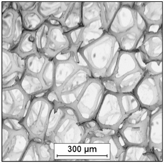
Figure 1.
SEM micrograph of Duocell reticulated vitreous carbon foam Cof of 100 ppi.
2.2. Methods of Cof-Mg Composite Characterization
The samples for microstructure observations were mechanically sliced out from composite discs, grinded and polished in kerosene. Then, they were examined without additional etching using a light microscope (LM, Nikon Eclipse MA-200, Nikon, Leuben, Belgium) and scanning electron microscope (SEM, Hitachi S-4200, Hitachi Group, Tokyo, Japan) equipped with an energy dispersive spectrometer (EDS) at an accelerating voltage of 15 kV (Si-Li detector Noran 3500, 130 eV resolution, Thermo Electron Corporation, Waltham, MA, USA).
The open porosity and density of composites were determined using the Archimedes method and the Brinnel hardness method (ball Ø = 5 mm, load F = 2.45 kN). For mechanical properties, characterization of compression tests (according to ASTM E9 standard, 3 samples of size 5.0 × 5.0 × 9.0 mm3) and flexural tests (according to ASTM C1161 standard, 3 samples of size 5.0 × 4.0 × 30 mm3) was performed, for which the Instron 4469 testing machine (Instron, Canton, MA, USA) was employed (strain rate 5 mm/min). The fractured cross-sections were characterized using SEM (Hitachi S-4200).
Tribological properties in dry friction conditions in air as friction coefficient, µ, and mass loss, Δm, were examined using a pin-on-disc method (Tribometer T-01M). For the experiment, the cast iron pin (Ø = 6 mm, friction radius = 7 mm) was used and tribological parameters were measured for a pin load of 24.5 N, velocity of 1 m/s and friction distance of 1000 m. Finally, the wear surface was characterized using SEM (Hitachi S-4200).
3. Results and Discussion
3.1. Macrostructure and Microstructure
Composite discs obtained using pressure infiltration are shown in Figure 2a, Figure 3a and Figure 4a. There are visible differences in their macrostructure. This observation agrees with that of light microscopy (LM) micrographs (Figure 2b, Figure 3b and Figure 4b) because it indicates a strong influence of the chemical composition of the matrix for infiltration effects. For the Cof–RZ5 composites, there were visible macropores and micropores as well as carbon foam damage. This reveals an inefficient infiltration of Cof by this magnesium alloy and destructive influence of the RE alloying elements on the carbon component. A similar effect was previously noted for stir-casting technology, which was applied for magnesium matrix composites that were used for manufacturing glassy carbon particles [16]. For the other two investigated composites, Cof–Mg and Cof–AZ31, the bonding between components is continuous and infiltration effects were favorable; however, the differences in interface microstructure because of the presence of the matrix alloying elements are evident (Figure 5, Figure 6 and Figure 7). In the Cof–Mg composite interface, only oxygen enrichment is detected because of the oxide bonding formation effect, which is typically observed in the C–Mg system. The reason for the MgO nanolayer’s presence at the interface is the high magnesium reactivity and a strong oxygen absorption by carbon materials. For the Cof–AZ31 composite, a zone formed at the interface is thicker with the presence of irregular, primarily slim phases (Figure 5b and Figure 7). Using EDS, we detected the enrichment of that zone with oxygen, aluminum and sometimes Mn. These results are in good agreement with those reported in the literature for high-resolution examination of C/Mg-Al-Mn systems, in which carbon fibers [36] and glassy (vitreous) carbon particles [13] were applied as reinforcing components. Using thin foils obtained from composites and selective area diffraction (SADP) and EDS techniques, the presence of matrix-alloy reaction products, such as oxides and hygroscopic carbides, as well as intermetallic phases of composition characteristic for matrix alloys, were observed. An effect of intermetallic phases’ accumulation at the interface region was observed by these two phenomena, their nucleation on the reinforcement surface and by pushing the crystallization front outside the α-Mg grains. Furthermore, our examination using SEM and EDS methods of the Cof–AZ31 composite corrosion in distilled water presented in reference [37] confirmed the presence of hydrophilic phases at the interface, which also indicated the occurrence of reactions between components during the consolidation process.
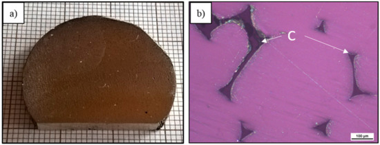
Figure 2.
(a) Macrograph and (b) LM micrograph of Cof–Mg composite obtained by pressure infiltration.
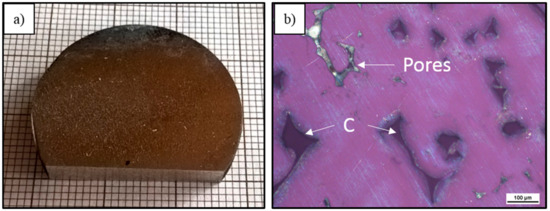
Figure 3.
(a) Macrograph and (b) LM micrograph of Cof–AZ31 composite obtained by pressure infiltration.
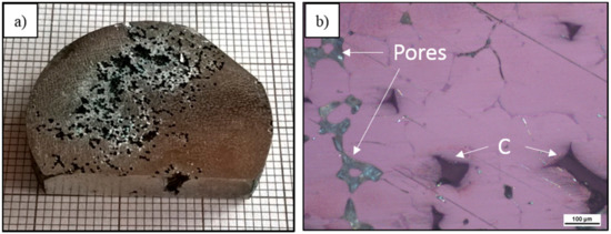
Figure 4.
(a) Macrograph and (b) LM micrograph of Cof–RZ5 composite obtained by pressure infiltration.
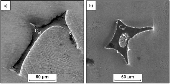
Figure 5.
SEM micrographs of: (a) Cof–Mg composite and (b) Cof–AZ31 composite, visibly different morphology of the interface region.
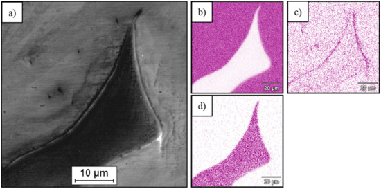
Figure 6.
(a) SEM micrograph of Cof–Mg composite with X-ray mapping of elements: (b) Mg, (c) O and (d) C.
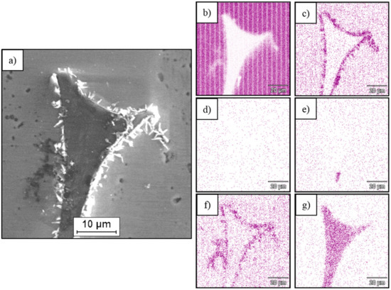
Figure 7.
(a) SEM micrograph of Cof–AZ31 composite with X-ray mapping of elements: (b) Mg, (c) Al, (d) Zn, (e) Mn, (f) O and (g) C.
3.2. Properties
3.2.1. Physical and Mechanical Properties
Table 2 lists the results of density and porosity measurements. The results show that ultra-light composite materials of density similar to magnesium matrix materials were obtained: 1.71 and 1.75 g/cm3 for Cof–Mg and Cof–AZ31, respectively. Note that the measured values of open porosity were in good agreement with the results of macrostructure and microstructure observations. They indicated that the best infiltration effect was observed for pure magnesium (porosity 1.4%), followed by a slightly worse performance for the AZ31 alloy (porosity 2.5%). These porosity values can be considered to be low; however, for the Cof–RZ5 composite, the porosity was ~9.8%, and this result along with that observed for carbon foam degradation induced by matrix alloy, indicates the irrelevance of the RZ5 alloy for further experiments.
Table 2.
Physical, mechanical and tribological properties of composites and component materials.
Note that in the composites that are processed via infiltration methods, two types of pores located can be formed, i.e., at the interface and within the metal matrix. One type arises because of the foam filling by the liquid metal, while the other type appears because of metal shrinkage. Moreover, the acceptable value of pressure in infiltration process of vitreous carbon skeleton (Cof) is limited because of the possibility of it being damaged. Furthermore, the influence of pressure on the final product’s porosity reduction is not so effective compared with the traditional metal die casting processes.
While analyzing the composites hardness measurements (Table 2), it is observed the value is different and increases in the following order: Cof–Mg, Cof–AZ31, and Cof–RZ5. Furthermore, the direction of hardness value increases in the same manner as that for applied matrices. However, the comparison of composite and matrix hardness reveals no change for the Cof–Mg system, an insignificant increase for the Cof–AZ31 system and an evident (18%) decrease for the Cof–RZ5 composite. Note that the results for Cof–RZ5 composite clearly confirm the irrelevance of the RZ5 matrix; therefore, further examination of that system was not continued.
Table 2 lists the compression tests results for composites and matrix materials, the examples for compression curves are presented in Figure 8, and fractured cross-sections are presented in Figure 9. The Rs value for both Cof–Mg and Cof–AZ31 composite was higher than for the matrix alloy, i.e., 6.5% and 36%, respectively. Similarly like for hardness, the Rs value was higher when the AZ31 alloy matrix was applied. The analyses of compression test curves shape (Figure 8) reveal an increase in composite stiffness; moreover, the effect is stronger when the pure magnesium matrix is used. The differences in the angle of inclination at the compression curves, in a range of elastic deformation, were observed, and the value is evidently higher for composites than for matrix material. That effect is stronger for the Cof–Mg system than for Cof–AZ31. The reason for the difference in the composite material properties is because of the matrix and interface microstructure. As per the SEM micrographs for both composites fractured surfaces (Figure 9), the shear bands of destroyed metal with strongly refined pieces of vitreous carbon foam were detected. However, in the Cof–AZ31 composite matrix, very fine irregular phases and micro-cracks were observed. Note that the compression test at macro-scale induced the destruction of composite samples by cracking propagation, which was independent of the composition of the applied matrix. For reference samples without carbon foam, the process was different because of plastic deformation and the change in sample shape.
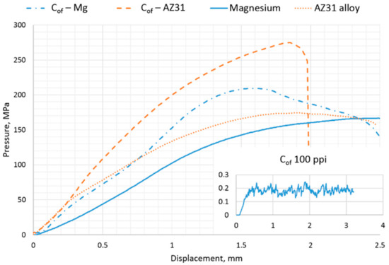
Figure 8.
Typical curves of compressive strength tests obtained for manufactured composites and applied components-matrix alloys and carbon foam.
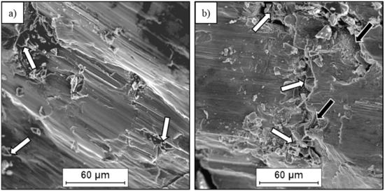
Figure 9.
SEM micrographs of fractured surface after compression tests: (a) Cof–Mg, (b) Cof–AZ31 composites, shear bands in magnesium matrix, scraps of destroyed carbon foam (white arrows), agglomerates of fine phases (black arrows).
The examples of flexural curves are shown in Figure 10, whereas fractured cross-sections are shown in Figure 11. For both these examined composites, the flexural strength was lower than that for reference matrix samples; moreover, a deformation that preluded the decohesion process was distinctly lower. This confirms the stiffness increase effect, which could be explained by a limited metal deformability because of its closing in the stiff carbon foam cells. Similar to the earlier characterized properties, the matrix alloy strength influenced the composite flexural strength and was higher when the AZ31 matrix is used. Moreover, the microstructure of fractured samples was quite different from those formed via compressive tests. The SEM micrographs of samples after the flexural tests (Figure 11) revealed a network of carbon foam for both Cof–Mg and Cof–AZ31 composites; however, for the Cof–AZ31 material, the foam was significantly damaged and multiple cracks in the carbon component were observed. Other differences in microstructure were detected in the metallic part of the composites within the foam cells. For the Cof–Mg composite, the shear effect was visible and the shear bands almost had the same orientation; however, in the Cof–AZ31 composite, they were detected only locally, and the areas of very fine regular phases were visible. The analyses of these dispersive phases showed a very similar shape to that of the foam walls’ shape (Figure 11b). This indicates their origin as the phases formed and cumulated at the interface when the components were getting consolidated. Therefore, it can be assumed that the phases formed at C-AZ31 alloy interface were strongly connected with the α-Mg grains. At the macro scale, the flexural tests of composites, like the compression test, induced the destruction of composite samples by cracking propagation and reference matrix materials by plastic deformation.
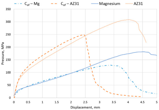
Figure 10.
Typical curves of flexural strength tests obtained for manufactured composites and reference matrix alloys.
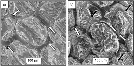
Figure 11.
SEM micrographs of fractured surface after flexural tests: (a) Cof–Mg, (b) Cof–AZ31, shear bands in magnesium matrix, network of partly destroyed carbon foam (white arrows), agglomerates of fine phases (black arrows).
Generally, the results of Cof–Mg and Cof–AZ31 composites’ mechanical properties show that a stronger increase in the properties could be obtained for the AZ31 matrix application, although they had a slightly higher porosity.
3.2.2. Tribological Properties
Figure 12 shows the curves of friction coefficient value, µ, versus friction distance (1000 m). Table 2 lists the mean µ value with a sample mass loss, Δm. Furthermore, the influence of the magnesium matrix’s composition on tribological properties of a composite reinforced with a similar type of carbon foam was observed. For the Cof–Mg composite, a slight increase in µ value with evident reduction of variability and multiple times mass loss reduction, Δm, was measured and compared with the reference Mg sample. However, the comparison of the Cof–AZ31 composite with the matrix material demonstrated both a strong increase of µ value with stability decrease and an increase in sample mass loss of >100%. When we compare the tribological properties of the two examined composites, we notice that, for the Cof–Mg composite, a lower and more stable µ value and a higher wear resistance is observed.
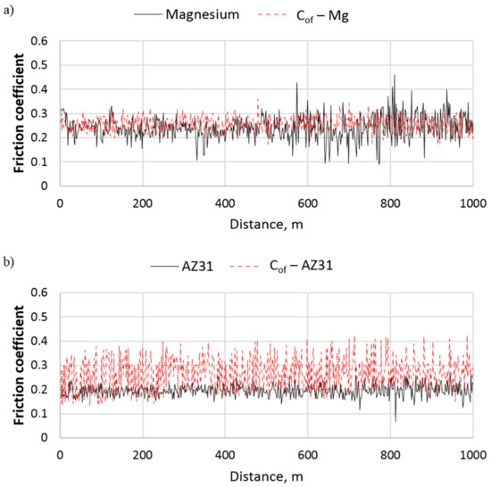
Figure 12.
Changes of friction coefficient determined for composites and reference matrix alloys over a distance of 1000 m, (a) magnesium and Cof–Mg, (b) AZ31 alloy and Cof–AZ31.
The results of surface examination of materials after dry friction tests exhibited different structural effects (Figure 13). At the Cof–Mg surface, the initial geometry of the Cof was not observed because the carbon component was transformed into fine pieces, which were embedded in soft magnesium. Moreover, at the composite surface, very fine globular oxides (white) and parallel distributed grooves in a metal matrix were observed; however, their depth was less than similar to that for a sample of pure Mg (Figure 13a). A surface state formed after dry friction test indicates tribofilm creation, i.e., a mixture of very fine metal, carbon and oxide molecules; moreover, it explains the µ value stabilization and wear resistance increase too.
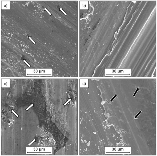
Figure 13.
SEM micrographs of materials surface after dry friction tests: (a) Cof–Mg composite, (b) Mg, (c) Cof–AZ31 composite, (d) AZ31 alloy, microareas of carbon component (white arrows), cracks and delamination effect (black arrows).
At the surface of the Cof–AZ31 composite (Figure 13c), the shallow grooves in the matrix were formed after dry friction. Moreover, the initial foam geometry and continuous bonding foam-matrix alloy were preserved. The analyses of carbon component surface morphology revealed its foam degradation process via crumbling of fine pieces and the effect of wear product agglomeration at the foam edges. When the AZ31 alloy was examined, it exhibited grooves, cracks and delamination effect at the wear surface (Figure 13d). When we compared these obtained results of the Cof–AZ31 composite tribological tests with earlier studies that were focused on magnesium alloys and composites with particle and short carbon fiber reinforcement [12,14,38], we did not notice the expected effect of properties improvement in the dry friction condition, which requires further analysis. At this stage of our study, we can assume that the formation of a solid tribofilm with carbon molecules is much more difficult when the source of carbon is a stiff skeleton (Cof) that is strongly bonded to the metal matrix.
To summarize, the results of our investigations confirmed the usefulness of the pressure infiltration method for carbon open-celled consolidation with magnesium base alloys. In future experiments, the matrix chemical composition design issue needs to be analyzed because the improvement of magnesium’s mechanical properties is only a possibility; due to the physical and chemical impact of the components, it does not guarantee that an increase in composite properties will be obtained. The next research problem that needs to be examined is the role of carbon foam geometry, i.e., cell size, wall thickness and window size, for the infiltration process, as well as their influence on final products properties because an effective increase in the carbon component volume fraction in the composite will provide a new perspective for future applications. Solving of these issues should let us apply the magnesium matrix composite with carbon foams in automotive vehicles, because in addition to having advantageous mechanical and tribological properties, a beneficial vibration damping induced by the cellular reinforcement form can also be expected.
Considering the possibility of Cof–Mg composite application as a biomaterial, extensive studies are needed, especially corrosion tests in simulated body fluids and on the effects of corrosion processes on hydrogen evolution as well as mechanical properties. Afterwards, experiments with assistance of biological cells on the composite surface and observation of their behavior should also be conducted.
4. Conclusions
In this study, we presented possibilities of a new ultra-light magnesium base matrix composite that was reinforced with open-celled carbon foam (3 vol. %), which was developed using the pressure infiltration method. We also demonstrated the dependence of the composite microstructure and related properties on the applied matrix chemical composition. Thus, the following conclusions have been drawn based on the results obtained:
- (1)
- From the examined matrices of the three different chemical compositions, an effective pressure infiltration at the same temperature and pressure conditions were obtained for the pure Mg and AZ31 alloy. This effect was greater for the Mg matrix.
- (2)
- Application of the magnesium alloy with the rare elements (RZ5 alloy) was ineffective because a porous composite with macropores and micropores was obtained. Moreover, the Cof chemical interaction occurred, which induced the degradation of the foam surface.
- (3)
- The open-celled carbon foam that was used as a reinforcing component for pure magnesium and magnesium AZ31 alloy increased the compressive strength and stiffness. A stronger increase of compressive strength compared with the matrix material was obtained when the AZ31 alloy was applied. This can be explained by a different microstructure and properties of interface in Cof–AZ31 compared to the Cof–Mg composite.
- (4)
- An application of open-celled carbon foam induced a decrease of flexural strength independently of the matrix composition, and that effect can be explained by limited deformation of the metal enclosed within the stiff carbon skeleton.
- (5)
- The presence of a glassy carbon component in the form of open-celled foam in a pure magnesium matrix caused an increase in the stability of the friction coefficient value in dry friction conditions and wear resistance. However, for composites with the AZ31 matrix, the tribological properties were worse compared to those obtained for a pure matrix alloy.
- (6)
- The wear surface studies revealed a different carbon foam behavior for the examined composites, which indicates an influence of the matrix composition on the wear mechanism and tribological properties.
5. Patents
Presented fabrication method of composite is patented by Urząd Patentowy Rzeczypospolitej Polskiej (Polish Patent Office), Patent Application No. P.422243, Olszówka-Myalska A., Myalski J., Godzierz M., Hekner B. “Method for production magnesium elements that contain inserts from carbon foams”.
Author Contributions
Conceptualization, A.O.-M. and J.M.; methodology, A.O.-M., J.M., M.G.; validation, M.G.; investigation, M.G., J.M. and P.W.; writing—original draft preparation, A.O.-M.
Funding
This research received no external funding.
Acknowledgments
This research was funded by Silesian University of Technology, Faculty of Materials Engineering and Metallurgy as a part of statutory research.
Conflicts of Interest
The authors declare no conflict of interest.
References
- Dybowski, B.; Rzychoń, T.; Chmiela, B.; Gryc, A. The microstructure of WE43 MMC reinforced with SiC particles. Arch. Metall. Mater. 2016, 61, 393–398. [Google Scholar] [CrossRef]
- Zhang, H.; Zhao, Y.; Yan, Y.; Fan, J.; Wang, L.; Dong, H.; Xu, B. Microstructure evolution and mechanical properties of Mg matrix composites reinforced with Al and nano SiC particles using spark plasma sintering followed by hot extrusion. J. Alloys Compd. 2017, 725, 652–664. [Google Scholar] [CrossRef]
- Wong, W.L.E.; Gupta, M. Improving overall mechanical performance of magnesium using nano-alumina reinforcement and energy efficient microwave assisted processing route. Adv. Eng. Mater. 2007, 9, 902–909. [Google Scholar] [CrossRef]
- Rashad, M.; Pan, F.; Lin, D.; Asif, M. High temperature mechanical behavior of AZ61 magnesium alloy reinforced with graphene nanoplatelets. Mater. Des. 2016, 89, 1242–1250. [Google Scholar] [CrossRef]
- Olszówka-Myalska, A.; Maziarz, W.; Botor-Probierz, A. Microstructure of magnesium alloy ZRE1-glassy carbon composite interface. Solid State Phenom. 2014, 211, 109–114. [Google Scholar] [CrossRef]
- Meenashisundaram, G.K.; Seetharaman, S.; Gupta, M. Enhancing overall tensile and compressive response of pure Mg using nano-TiB2 particulates. Mater. Charact. 2014, 94, 178–188. [Google Scholar] [CrossRef]
- Wong, W.L.E.; Gupta, M. High performance lightweight magnesium nanocomposites for engineering and biomedical applications. Nano World J. 2016, 2, 78–83. [Google Scholar]
- Zhou, J.M.; Qi, L.H.; Ouyang, H.B.; Li, H.J. Mechanical properties of Csf/AZ91D composites fabricated by extrusion forming process directly following the vacuum infiltration. Adv. Mat. Res. 2010, 90, 692–696. [Google Scholar] [CrossRef]
- Habibi, M.K.; Paramsothy, M.; Hamouda, A.M.S.; Gupta, M. Enhanced compressive response of hybrid Mg–CNT nano-composites. J. Mater. Sci. 2011, 46, 4588–4597. [Google Scholar] [CrossRef]
- Olszówka-Myalska, A.; Myalski, J. Magnesium alloy AZ31-short carbon fiber composite obtained by pressure die casting. Solid State Phenom. 2015, 229, 115–122. [Google Scholar] [CrossRef]
- Hufenbach, W.; Andrich, M.; Langkamp, A.; Czulak, A. Fabrication technology and material characterization of carbon fiber reinforced magnesium. J. Mater. Process. Tech. 2006, 175, 218–224. [Google Scholar] [CrossRef]
- Ataya, S.; Alsaleh, N.A.; Seleman, M.M.E.S. Strength and wear behavior of Mg alloy AE42 reinforced with carbon short fibers. Acta Metall. Sin. 2018, 32, 31–40. [Google Scholar] [CrossRef]
- Olszówka-Myalska, A.; Myalski, J.; Botor-Probierz, A. Microstructural characteristics of an AZ91 matrix-glassy carbon particle composite. Adv. Eng. Mater. 2010, 12, 609–616. [Google Scholar] [CrossRef]
- Olszówka-Myalska, A.; Myalski, J.; Hekner, B. Tribological characteristics of the magnesium matrix-glassy carbon particles composite manufactured by different casting methods. In Proceedings of the European Symposium on Friction, Wear, and Wear Protection, Karlsruhe, Germany, 6–8 May 2014; pp. 1–9. [Google Scholar] [CrossRef]
- Uozumi, H.; Kobayashi, K.; Nakanishi, K.; Matsunaga, T.; Shinozaki, K.; Sakamoto, H.; Tsukada, T.; Masuda, C.; Yoshida, M. Fabrication process of carbon nanotube/light metal matrix composites by squeeze casting. Mat. Sci. Eng. A Struct. 2008, 495, 282–287. [Google Scholar] [CrossRef]
- Olszówka-Myalska, A. Some physicochemical phenomena observed during fabrication of Mg-C cast composites. J. Mater. Eng. Perform. 2016, 25, 3091–3097. [Google Scholar] [CrossRef]
- Kremzer, M.; Dziekońska, M.; Sroka, M.; Tomiczek, B. Abrasive wear of AlSi12-Al2O3 composite materials manufactured by pressure infiltration. Arch. Metall. Mater. 2016, 61, 1255–1260. [Google Scholar] [CrossRef]
- Dolata, A.J. Centrifugal infiltration of porous ceramic preforms by the liquid Al alloy—Theoretical background and experimental verification. Arch. Metall. Mater. 2016, 61, 411–418. [Google Scholar] [CrossRef]
- Dolata, A.J. Tribological properties of AlSi12-Al2O3 interpenetrating composite layers in comparison with unreinforced matrix alloy. Materials 2017, 10, 1045. [Google Scholar] [CrossRef]
- Posmyk, A.; Myalski, J. Composites including foam inserts designed for combustion engine cylinder liners. Compos. Theory Pract. 2017, 17, 25–29. [Google Scholar]
- Potoczek, M.; Śliwa, R.E. Microstructure and physical properties of AlMg/Al2O3 interpenetrating composites fabricated by metal infiltration into ceramic foams. Arch. Metall. Mater. 2011, 56, 1265–1269. [Google Scholar] [CrossRef]
- Inagaki, M.; Qiu, J.; Guo, Q. Carbon foam: Preparation and application. Carbon 2015, 87, 128–152. [Google Scholar] [CrossRef]
- Singh, M.; Asthana, R.; Gyekenyesi, A.L.; Smith, C.E. Bonding and Integration of Titanium to Graphitic Foams for Thermal Management Applications. Int. J. Appl. Ceram. Tec. 2014, 9, 657–665. [Google Scholar] [CrossRef]
- Spradling, D.M.; Guth, R.A. Carbon foams. Adv. Mater. Process. 2003, 161, 29–31. [Google Scholar]
- Czarnecki, J.S.; Blackmore, M.; Jolivet, S.; Lafdi, K.; Tsonis, P.A. Bone growth on Reticulated Vitreous Carbon foam scaffolds and implementation of Cellular Automata modeling as a predictive tool. Carbon 2014, 79, 135–148. [Google Scholar] [CrossRef]
- Pec, M.K.; Reyes, R.; Sanchez, E.; Carballar, D.; Delgado, A.; Santamaria, J.; Arruebo, M.; Evora, C. Reticulated Vitreous Carbon: A useful material for cell adhesion and tissue invasion. Eur. Cells Mater. 2010, 20, 282–294. [Google Scholar] [CrossRef]
- Rogulski, Z.; Lewdorowicz, W.; Tokarz, W.; Czerwiński, A. Applications of Reticulated Vitreous Carbon (RVC) in the electrochemical power sources. Pol. J. Chem. 2004, 78, 1357–1370. [Google Scholar]
- Ummethala, R.; Fritzsche, M.; Jaumann, T.; Balach, J.; Oswald, S.; Nowak, R.; Sobczak, N.; Kaban, I.; Rummeli, M.H.; Giebeler, L. Lightweight, free-standing 3D interconnected carbon nanotube foam as a flexible sulfur host for high performance lithium-sulfur battery cathodes. Energy Storage Mater. 2018, 10, 206–215. [Google Scholar] [CrossRef]
- Delabarde, C.; Plummer, C.J.G.; Bourban, P.-E.; Manson, J.-A.E. Biodegradable polylactide/hydroxyapatite nanocomposite foam scaffolds for bone tissue engineering applications. J. Mater. Sci. Mater. Med. 2012, 23, 1371–1385. [Google Scholar] [CrossRef]
- Gawdzińska, K. Study of metallic-ceramic composite foams with application of the computer tomograph. Metallurgija 2015, 54, 671–674. [Google Scholar]
- Gawdzińska, K.; Grabian, J.; Gucma, M.; Kwiecińska, B. Deformation mechanisms in metal composite foams. Metallurgija 2016, 55, 37–40. [Google Scholar]
- Godzierz, M.; Olszówka-Myalska, A.; Wrześniowski, P. The interaction characteristics of liquid magnesium and selected magnesium alloys with open-celled glassy carbon foams. Mater. Eng. 2018, 39, 61–67. [Google Scholar] [CrossRef]
- Olszówka-Myalska, A.; Myalski, J.; Godzierz, M.; Wrześniowski, P. Magnesium matrix composite with open-celled carbon foams obtained by powder metallurgy. Arch. Metall. Mater. 2018, 63, 825–831. [Google Scholar]
- Magnesium Elektron. Available online: https://www.magnesium-elektron.com/ (accessed on 1 May 2019).
- Doucell Reticulated Vitrous Carbon Foam Datasheet. Available online: https://ergaerospace.com/materials/duocel-reticulated-vitreous-carbon-rvc-foam/ (accessed on 1 May 2019).
- Feldhoff, A.; Pippel, E.; Woltersdorf, J. Carbon-fiber reinforced magnesium alloys: Nanostructure and chemistry of interlayers and their effect on mechanical properties. J. Microsc. Oxf. 1999, 196, 185–193. [Google Scholar] [CrossRef]
- Godzierz, M.; Olszówka-Myalska, A. Microstructural corrosion effects on carbon foam-AZ31 magnesium matrix composite surface. Compos. Theory Pract. 2018, 18, 133–139. [Google Scholar]
- Olszówka-Myalska, A.; Myalski, J.; Botor-Probierz, A. Effect of glassy carbon particles on wear resistance of AZ91E matrix composite. Solid State Phenom. 2011, 176, 127–138. [Google Scholar] [CrossRef]


© 2019 by the authors. Licensee MDPI, Basel, Switzerland. This article is an open access article distributed under the terms and conditions of the Creative Commons Attribution (CC BY) license (http://creativecommons.org/licenses/by/4.0/).