Article

Experimental and FEM Analysis of Void Closure in the Hot Cogging Process of Tool Steel

Faculty of Mechanical Engineering and Computer Science, Częstochowa University of Science and Technology, 42-200 Czestochowa, Poland
Metals 2019, 9(5), 538; https://doi.org/10.3390/met9050538
Submission received: 29 March 2019 / Revised: 25 April 2019 / Accepted: 9 May 2019 / Published: 10 May 2019

Abstract

:
In the present study, a new complex methodology for the analysis the closure of voids and a new forging system were developed and tested. The efficiency of the forging parameters and the effective geometric shapes of anvils to improve void closure were determined. A new cogging process provided a complete closure of an ingot’s axial defects, as confirmed by experimental tests. The evolution behavior of these defects with different sizes was investigated during the hot cogging process by means of the professional plastic forming software Deform-3D. A comprehensive procedure was developed using the finite-element method (FEM) for the three-dimensional cogging process and laboratory experimentation to predict the degree of void closure. The hot multi-pass cogging process was used to eliminate void defects in the forgings so as to obtain sound products. In the compression process, the effects of the reduction ratio and forging ratio, the void size, and the types of anvil were discussed to obtain the effective elimination of a void. For the purpose of the assessment of the effectiveness of the void closure process, the following indices were introduced: the relative void volume evolution ratio, the relative void diameter ratio, and the internal void closure evaluation index. Moreover, the void closure process was assessed on the basis of stress triaxiality, hydrostatic stress, forging ratio, value of local effective strain around the void, and critical reduction ratio. The results of this research were complemented by experiments predicting the formation of fractures in the regions near the void and in the volume of the forging in the course of the cogging process. The comparison between the predicted and the experimental results showed a good agreement.

1. Introduction

The structure and properties of a billet shaped by means of the forging method are determined by the properties of the initial ingot and by the parameters of the technological process. The internal defects of ingots, such as porosity, internal voids, and damage ought to be removed in the course of the forging process or to be reduced to the greatest possible degree [1,2,3]. Computer simulations based on the finite-element method (FEM) have become a popular tool for the investigation of the void closure process in forging processes [4,5,6]. In some works [7,8,9], the local values of hydrostatic stress and effective strain were considered as criteria of void closure, and a greater importance was assigned to the values of effective strain.
Such an approach was confirmed in other works [10,11], in which a mathematical function was introduced for the purpose of determining the distribution of strain. Nevertheless, this did not allow to determine the criterion of void closure precisely. Kakimoto et al. [12], for the purpose of the assessment of internal voids closing, put forward the internal void closure evaluation index. The authors confirmed a significant influence exerted by stress field and strains in the environment of the void on the value of the adopted criterion. The minimum threshold value of this criterion, amounting to 0.21, was not confirmed in the study of Zhang et al. [13], in which the threshold value of this criterion was elevated to 0.85. In the works of Saba et al. [14] and Chen et al. [15], numerical analyses of the void closure process for the axial-symmetrical upsetting process with the application of the model of the Representative Volume Element (RVE) were performed. The following works of Feng and Cui [16] and of Feng et al. [17] extended the model of the RVE to the three-dimensional description of the void closure process in the course of forging. By combining the model of the RVE with the distribution of stresses and strains around the existing discontinuities, the efficiency of void closure in the ingot forging process was investigated.
For that very reason, in numerous contemporary works [18,19,20], we still encounter the analyses of stress triaxiality, mean stresses, hydrostatic stresses, critical reduction ratio, and local effective strain in the axial zone of a deformed billet, most frequently in flat tools. Accomplishing qualitative objectives in the course of the production of important and responsible forgings requires the complete elimination of the defects of metallurgical origin to reach high-quality functional properties. This requires the broad application of shape tools and optimum technological parameters in the forging processes.
Despite the wide literature concerning the void closure in casting ingots, there is a lack of information on void closure efficiency in the cogging process when selecting different forging parameters and shaped anvils. This research aims to fill this lack by further investigating the effects of hot-forging parameters and deformation shaped tools (originated in this paper) on the reduction of voids. In this paper, a new complex methodology for the analysis of void closure was tested.
For the purpose of this work, comprehensive numerical investigations, confirmed by experimental investigations, of the cogging process in ingots made of tool steel were performed by the assessment of the efficiency of the axial closure process of voids with different sizes. For the purpose of the quantitative assessment of the axial void closure process, the following indices were used: relative void diameter ratio, void area ratio, relative void volume evolution ratio, and internal void closure evaluation index. Furthermore, for the purpose of the assessment of axial void closure, the following variables were evaluated: hydrostatic stress, stress triaxiality, reduction ratio, forging ratio, and local effective strain value around voids. The present study attempted to find the most influencing parameters characterizing the void closure process and determine their quantitative effects by examining changes in the process and deformation shaped tools originated in this paper. Computer simulations and experimental investigations were performed with the application of flat and V-shaped anvils and of the optimum technological parameters. The results of the investigations were complemented with the prediction of the formation of damage in the area around an axial void.

2. Theoretical Analysis

2.1. Basic Equations of the Thermal-Mechanical FEM

The FEM of the cogging process was used. According to a variational principle, the functional for a billet can be written as [21]:
δ ϕ = V σ ¯ δ ε ¯ ˙ d V + V K ε ˙ v δ ε ˙ v d V S F i δ v i d S = 0
where δ ϕ is the variational form of functional ϕ , δ ε ¯ ˙ is the virtual effective strain rate, σ ¯ is the effective stress, δ ε ˙ v is the virtual volumetric strain rate, ε ˙ v is the volume strain rate, V is the volume of the billet, F i is the traction at the surface S, δ ν i is the virtual velocity, K is the penalty constant. Here, the penalty constant K was set to be 106.
The analysis of heat transfer can also be readily conducted by solving the following energy balance equation:
k 2 T + q ˙ ρ   c   T ˙ = 0
where T is the temperature, k is the thermal conductivity, q ˙ is the heat generation rate, c is the specific heat, ρ is the specific density, T ˙ = T / t , t is a time interval, k 2 T represent the heat-transfer rate, ρ   c   T ˙ is the heat-generation rate. The rate of heat generation in the deformed body due to plastic deformation is given as:
q ˙ = α σ ¯ ε ¯ ˙
where q ˙ is the heat-generation efficiency, and α is the fraction of mechanical energy converted into heat and is assumed to be 0.9. The energy equation, Equation (2), can be rewritten using the weighted residual method as:
V k T , i δ T , i d V + V ρ c T ˙ δ T   d V V α σ ¯   ε ¯ ˙   δ T   d V S q n δ T   d S = 0
where qn is the heat flux normal to the boundary surface. The temperature distribution of the forgings can be obtained readily by solving the above energy balance equation.
The effect of friction at the billet–anvils interface can be considered by means of the following equation:
f = m   τ p [ 2 π tan 1 ( | v s | a ) ] t
where f is the frictional stress, v s is the velocity vector of the workpiece relative to the anvil, a is a small constant ( a = 0.0001), m is the friction factor (0 ≤ m ≤1), and τ p is the local flow stress in shear.

2.2. Ductile Fracture Criterion

In the present work, the model proposed by Cockroft and Latham was applied. Considering the ratio between the highest tensile stress ( σ * ) and the effective stress ( σ ¯ ), Cockroft and Latham proposed the Normalized C&L criterion, which is as follows:
0 ε ¯ f σ * σ ¯ d ε ¯ C C L
where ε ¯ f is the effective strain at fracture, ε ¯ is the effective strain, and CC-L is the critical value of ductile fracture of the material.
Tensile tests were performed to determine billet properties and the critical value of ductile fracture of X40CrMoV511 steel. The uniaxial tensile experiment was performed with the use of a thermo-simulation machine. The tensile temperatures were between 1173 and 1373 K, while the strain rates were 0.25–2.5 s−1. The peak stresses at different temperatures and strain rates could then be obtained. The experimental strain values, where the stress–strain curves drop suddenly, were regarded as ε ¯ f .

2.3. Criteria for Void Closure

For the quantitative analysis of the closure of axial void, the following indices were considered, which are defined as follows:
η d = d f d 0   or   η A = S f S o
where η d is the relative void diameter ratio, d0 is the initial void diameter, df is the void diameter in the vertical direction after deformation, ηA is the void area ratio, S0 is the initial hole cross-sectional area, and Sf is the final hole cross-sectional area after deformation;
η V = V i V 0 i
where η V is the relative void volume evolution ratio, V0i and Vi are the initial volume and the remaining volume of a void at some deformed stage, respectively;
Q = 0 ε ¯ f ( σ m σ ¯ ) d ε ¯ = i = 1 n ( σ m / σ ¯ ) i Δ ε ¯ i
where Q is the internal void closure evaluation index (Q value), as introduced by Kakimoto et al. [12], σm is the hydrostatic stress, σ ¯ is the effective stress, ε ¯ is the effective strain, ε ¯ f is the final effective strain, n is the number of steps, ( σ m / σ ¯ ) i is the value of σ m / σ ¯ at step i, Δ ε ¯ i is the incremental effective strain in step i. The parameters calculated from (7) and (8) describe the degree of the closure of axial void at each forging pass. When η d , η A , and η V become 0, the axial void will be closed. Moreover, for the evaluation of the void closure process, the hydrostatic stress, the stress triaxiality ( σ m / σ ¯ ), the local effective strain value around voids, the reduction ratio, and the forging ratio were used.

2.4. Thermal-Mechanical FEM for Void Evolution

For the analysis of the cogging process, an FE method-based commercial software program, DEFORM-3D (Version 2018, Scientific Forming Technologies Corporation, Columbus, OH, USA), was used. The meshed finite-element model for the initial billet and the schematic of the initial voids is shown in Figure 1. The surface of a cross section was located in the mid-length of the billet. The three-dimensional models of billet, top anvil, and bottom anvil, which were drawn by program Solid Works (2017, Dassault Systemes SolidWorks Corporation, Waltham, MA, USA), were imported into Deform-3D. The hole diameter was much larger than the expected voids which are typically found in a cast ingot (Figure 2), hence, it represented the worst-case condition. For the purpose of numerical calculations and of experimental model investigation, the following charge was adopted: φ 80 mm × 200 mm, made of the X40CrMoV511 steel having the following chemical composition: C—0.40%, Mn—0.40%, Si—1.05%, Cr—5.0%, Mo—1.35%, V—0.90%. The tetrahedral element was used in the meshed billet, and the number of elements was 200,298. The void closure process during forging in V-shaped anvils with an impression angle of 130° × 130° is shown in Figure 3. The process conditions in the FE simulation and some thermal physical properties of the workpiece were as follows: (1) The friction factor between the billet and the anvil was 0.7 (the friction factor was determined from additional ring compression tests); (2) The reduction ratio varied from 0.01 to 0.35 with an interval of 0.01 (the reduction ratio is defined as lnh1/h, where h and h1 are the height of the initial and the deformed billet, respectively); (3) The feed rate amounted to 0.75 in each pass; (4) The environment temperature was 293 K; (5) The initial forging temperature was 1373 K; (6) The initial anvils temperature was 573 K; (7) The convection coefficient to the environment was 0.02 N/(s·mm·°C); (8) The heat-transfer coefficient between the deformed billet and the anvils was 5 N/(s·mm·°C); (9) The anvil pressing speeds were 10 mm/s and 50 mm/s for the billet and the ingot, respectively.

2.5. Experimental Campaign and Computational Conditions

In order to obtain the properties of the examined X40CrMoV511 steel at elevated temperatures, plastometric investigations were conducted for the different values of strain and strain rateand for a fixed hot plastic working temperature range ( σ ¯ = f ( ε ¯ , ε ¯ ˙ , T ) ). The experimental tests included compressing φ 30 mm × 30 mm axially symmetric specimens on a cam plastometer of the MAEKAWA–Japan type. The specimens were deformed in the temperature range of 1173–1473 K, for a strain rate range of 0.25–3.5 s−1 and a true strain range of 0.105–0.693. The specimens were heated up to the deformation temperature in an automatically controlled electric furnace. An example of the relationship between true stress and true strain at different temperatures for two selected strain rates, i.e., 2.5 s−1 and 3.5 s−1, and for three temperature values, i.e., 1123 K, 1223 K, and 1473 K, is shown in Figure 4.
The shape and size of the introduced initial void are illustrated in Figure 5a, the geometrical model of the anvils and deformed billet is presented in Figure 5b, the hitting sequence of the cogging process is shown in Figure 5c, and the schematic diagram of technological passes is presented in Figure 5d. For the purpose of the investigation, a circular-cylindrical void, situated in the center of a deformed billet, was applied. The ratio between the size of the hole and the billet diameter ranged from 0.05 to 0.20 (d0/D0), therefore, varying void diameters were simulated: 4.0 mm, 8.0 mm, and 16.0 mm. The forging was performed in the course of several consecutive passes with rotations of 90° while maintaining, in every step, a constant value of the true reduction ratio ε = 0.35 and a constant feed rate lw = 0.75. The cogging process was done in flat anvils (Figure 6a), V-shaped anvils with an angle of 130° × 130° (Figure 6b), and in an assembly of three-radial anvils (Figure 6c). The number of passes used in the cogging process in particular tools was determined by the complete closure of an axial void. Figure 7 illustrates the set of anvils used in the experimental investigations.
For the X40CrMoV511 steel, the limiting value of the fracture criterion, CC-L, was determined by the comparative method based on the notch uniaxial tensile test. The limiting Cockroft–Latham value, as determined from the tensile test for the investigated temperatures (1373–1273 K) and the assumed strain rates, amounted to ψCL = 0.66–0.57.

3. Results and Discussions

The local values characterizing the state of deformation, state of stress, and temperature distribution and the values of the Normalized C&L criterion in regions around the closing void and in the volume of a forging in the course of the cogging process of the X40CrMoV511 steel on flat anvils, V-shaped anvils, and an assembly of the three-radial anvils, were determined. The choice of flat anvils was dictated by their wide use in industrial practice.
Figure 8 shows the distribution of effective strain and mean stress on the cross-sectional surface, located in the mid-length of the billet after the cogging process on flat anvils. The change in the selected axial void having the initial diameter of 16mm (d0/D0 = 0.20) in three consecutive technological passes is presented, with turning after each pass by a rotation angle of 90°. The state of stress and of strain around an existing void significantly influenced the process of its evolution in the aspect of shape and size. The greatest deformations occurred in the central part of a forging, in which the greatest metallurgical discontinuities in the form of voids and a central pore occurred (shown in Figure 8A). In this region, the values of effective strain ε ¯ exceeded the value of the preset reduction ratio ε ( ε ¯ / ε = 1.25). The region adjacent to the surfaces of the anvils experienced a small effective strain ( ε ¯ / ε = 0.35–0.55), whereas the side zones of the forging were the regions of indirect effective strain ( ε ¯ / ε = 0.55–0.85). In the first technological pass, the region around the axial void was subjected to tensile stress (shown in Figure 8B), and, in the subsequent pass, underwent improvement. At the moment of concluding the axial void closure process (shown in Figure 8B(c)), the compressive stress in the central part of the forging was observed.
Figure 9 shows the distribution of effective strain and mean stress on the cross-sectional surface during the cogging process on V-shaped anvils with an impression angle of 130° × 130° (d0/D0 = 0.20). The V-shaped anvils turned out to be more efficient than the flat anvils. On the majority of a cross section, a very favorable and nearly uniform effective strain distribution was obtained, whereas the region having the maximum values of effective strain was situated in the direct vicinity of the center in the deformation zone and was subjected to an effective strain of ε ¯ / ε = 2.35–2.55 (shown in Figure 9A). Such large values of effective strain in the axial zone of a billet being deformed brought about the conditions favorable to axial void closing already at the stage of the first technological pass (Figure 9A(b)). Deviations in the effective strain distribution existed in the corners and in the side zones of the forging. At the initial stages of the first technological pass, the region around the axial void was subjected to tensile stress (shown in Figure 9B) and, at the final stage of concluding axial void closure process, underwent a favorable change.
Figure 10 shows the distribution of effective strain and mean stress on the cross-sectional surface of a forging deformed in the assembly of three radial anvils during and after the third pass (d0/D0 = 0.20). The largest values of effective strain were seen in the regions of a forging situated under the convex surfaces of the anvils, whereas the central parts of the forging were the region characterized by the smaller values of effective strain (Figure 10A). Closing of the smallest axial void (d0/D0 = 0.05) occurred in the second technological pass, whereas the remaining voids (d0/D0 = 0.10 and 0.20) still required an additional pass (Figure 10A(b)). The efficiency of the assembly of three radial anvils in the void closure process was, admittedly, lower than that of the V-shaped anvils. A major advantage of forging on these anvils is comparatively high uniformity of the effective strain distribution in the deformation zone and the absence of tensile stress in the axial workpiece zone (shown in Figure 10B).
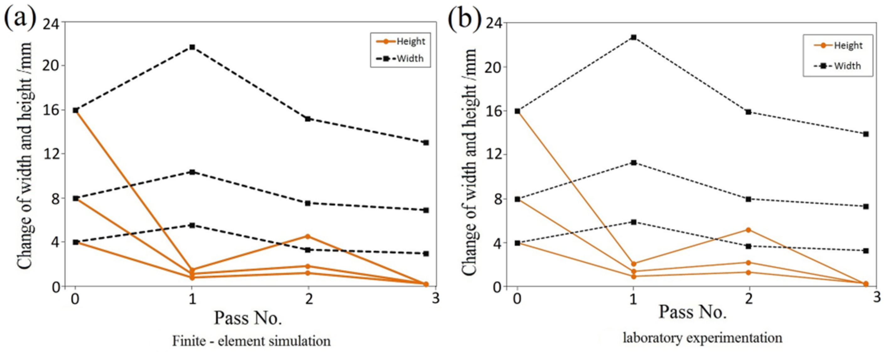
Changes in the width and height of the axial voids being researched, are presented in Figure 11a. The results of numerical research were confirmed experimentally, as shown in Figure 11b. Figure 12a shows changes of the area ratio of the axial void ηA at different cogging passes during deformation on flat anvils. The results of numerical research were confirmed experimentally, which is shown in Figure 12b. It was observed that voids with different diameters were closing during the cogging process at the third pass.
Figure 13 displays the relationship between effective strain and the relative void diameter ratio ηd at different sizes of voids (d0/D0) with different anvils shapes. V-shaped anvils appeared to be the most effective tool, allowing axial voids to close in the presence of effective strain in the central part of the forging amounting to ε ¯ = 1.20. On flat anvils, the axial void closure process occurred in the case of ε ¯ = 1.80–2.0, whereas higher values were necessary for larger voids (d0/D0 = 0.20). The assembly of three radial anvils required intermediate values of effective strain for the closure of axial voids ( ε ¯ = 1.60).
The comparison of the efficiency of void closure with the three different tools is shown in Figure 14, which, in the form of the relative void diameter ratio (ηd), characterizes the axial void closure process concerning voids of three sizes (d0/D0 = 0.05, 0.10, 0.20) in consecutive passes. Within the experimental part of the research, tests were conducted for identical cogging process parameters, using the same tools as those described in the numerical study methodology section. For laboratory tests, φ 80 mm-diameter and 200 mm-long cylindrical specimens were used, and in the mid-length of each specimen (after cutting), a hole of a diameter and depth identical to those of the numerical model was drilled. The samples were heated in a resistance furnace up to the temperature of 1373 K and afterwards deformed on a hydraulic press exerting a pressure of 2.5 MN. After the deformation, the specimens were cut at 0.5 of their length, the cut surfaces were ground, the geometrical measurements of voids were performed, and then the shapes and dimensions of the voids were compared, after particular passes, with the theoretical results. Figure 14a–c shows that the predicted results of the numerical investigation concerning the relative void diameter ratio (ηd) for axial voids with three different sizes were in complete agreement with the measurements in the experimental investigation.
Figure 15 presents a view of the selected macro-sections of specimens after closing an axial void (d0/D0 = 0.20) forged in anvils of different shapes. The investigation showed that the best result in closing an axial cylindrical void was obtained from cogging in V-shaped anvils. Using those anvils was very efficient in terms of void closure, as the cogging resulted in almost a complete closure of the void in the first forging pass (Figure 15c). The use of flat anvils required a much larger total deformation; after the third pass the upper and lower void surfaces were closed together simultaneously, which was confirmed by experimental tests (Figure 15b). Figure 15d shows a view of a macro-section after the third pass with the assembly of three radial anvils demonstrating levelling of the formed unevenness in flat anvils.
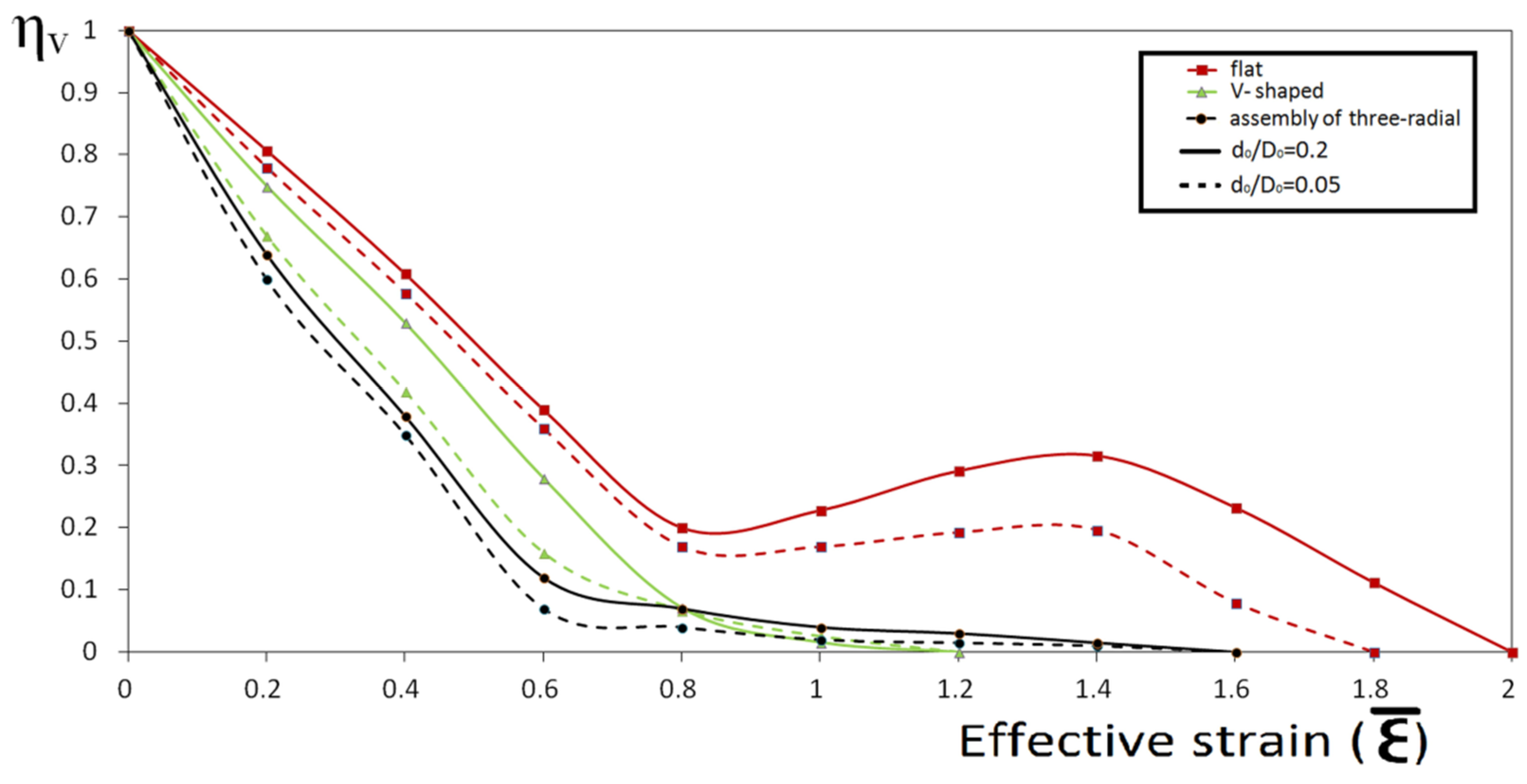
The distribution of the relative void volume evolution ratio (ηV) as the function of effective strain and anvils shape is shown in Figure 16. The complete closure of an axial void occurred when the effective strain around it reached the values of 1.20, 1.60, and 1.80–2.0 for the V-shaped anvils, the assembly of three radial anvils, and the flat anvils, respectively; the value ε ¯ = 2.0 concerned the void having larger size (d0/D0 = 0.20). The value of the effective strain indispensable for the closure of the void was a very effective parameter.
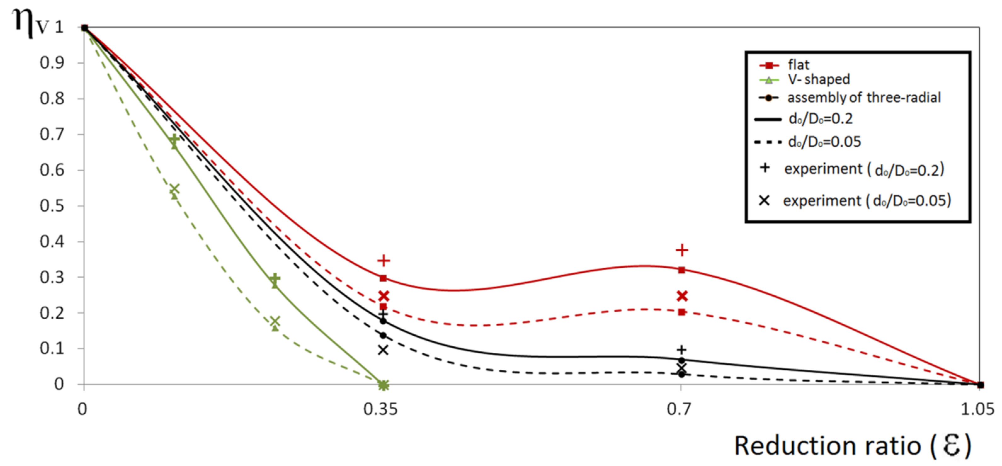
The relative void volume evolution ratio as a function of the reduction ratio and the shape of anvils is shown in Figure 17. For the purpose of the assessment, the total reduction ratio and three shapes of anvils were considered. For the verification of the theoretical studies, selected experimental test results are presented for the same tools and the same cogging process parameters as those adopted in the computer simulations of void closing. The experimental test results after particular passes are plotted in Figure 17. It was observed that the changes in morphology of voids having different initial diameters were similar. V-shaped anvils turned out to be the most effective in the void closure process. After the first pass, all three differentially sized axial voids underwent a complete closure (ε = 0.35). In the assembly of three radial anvils and in flat anvils, a complete closure of all three differentially sized axial voids occurred after the third pass (ε = 1.05). The processed results showed that the predicted results of the numerical investigation concerning the relative void volume evolution ratio were in a full agreement with those of the experimental investigation.
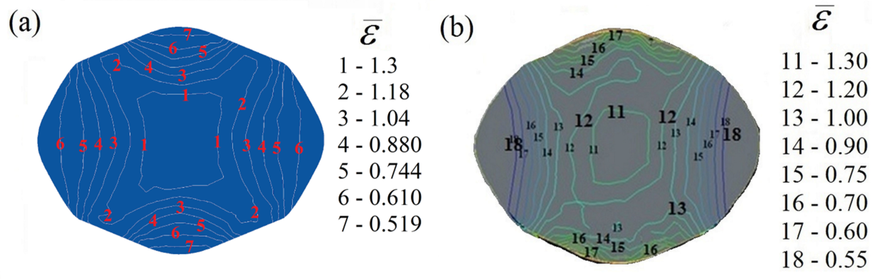
The results of the experimental and numerical investigations of the distribution of the effective strain in the course of cogging in V-shaped anvils (α = 130° × 130°) are shown in Figure 18. The state of strain was determined with the application of the coordinate grid method. The performed comparative analysis of the effective strains obtained by means of numerical calculations and of experiments manifested a comparatively good agreement between them.
The initial billet with a void of different sizes for the multi-pass cogging process in flat anvils, in the form of an initially forged ingot having the dimensions φ 800 mm × 2000 mm, is shown in Figure 19. The relative sizes of the void were the same as in the model investigations (d0/D0 = 0.05, 0.10, and 0.20). The same diagram of passes as in the model investigations was applied. The forging was performed in eight consecutive passes in order to reach the forging ratio of K = 3.0 (with interoperation rotation of 90°), while maintaining a reduction ratio of ε = 0.35 and a constant feed rate of lw = 0.75 in every pass. The initial temperature of the billet was 1373 K, and that of the anvils was 573 K. The choice of flat anvils in further analysis of the void closure process was determined by their frequent application in industrial practice.
Figure 20a illustrates the results of the calculations of stress triaxiality for axial voids with different sizes, i.e., d0/D0 = 0.05, 0.10, and 0.20 in the course of cogging in eight passes (forging ratio K = 3.0) in flat anvils. The figure shows that the first two passes were completed in the presence of tensile stresses around the void. Commencing with the third passes, a higher hydrostatic pressure, which increased the effectiveness of void closure, was generated. All the sizes of the axial void, commencing with the third pass, underwent deformation in the presence of compressive stresses. The correlation between the effective strain and the total reduction ratio is shown in Figure 20b. While the reduction ratio was increasing, the values of the effective strain around the axial void were rising intensively, regardless of the size of it, which exerted a positive influence on the process of void closure.
The variation of the void closure evaluation index (Q value) as a function of the reduction ratio and for three sizes of axial void (d0/D0 = 0.05, 0.10, and 0.20) is plotted in Figure 21. The presented correlations give rise to the claim that the values of Q value for particular sizes of axial void were between 0.75 and 0.85, according to the closure time.
In the practice of cogging, a very important parameter in the assessment of the internal quality of forgings is the minimum critical forging ratio. In the contemporary production process, in order to ensure that all voids can be eliminated, it is recommended that the critical forging ratio amount to 3.0, as confirmed by Zhang et al. [
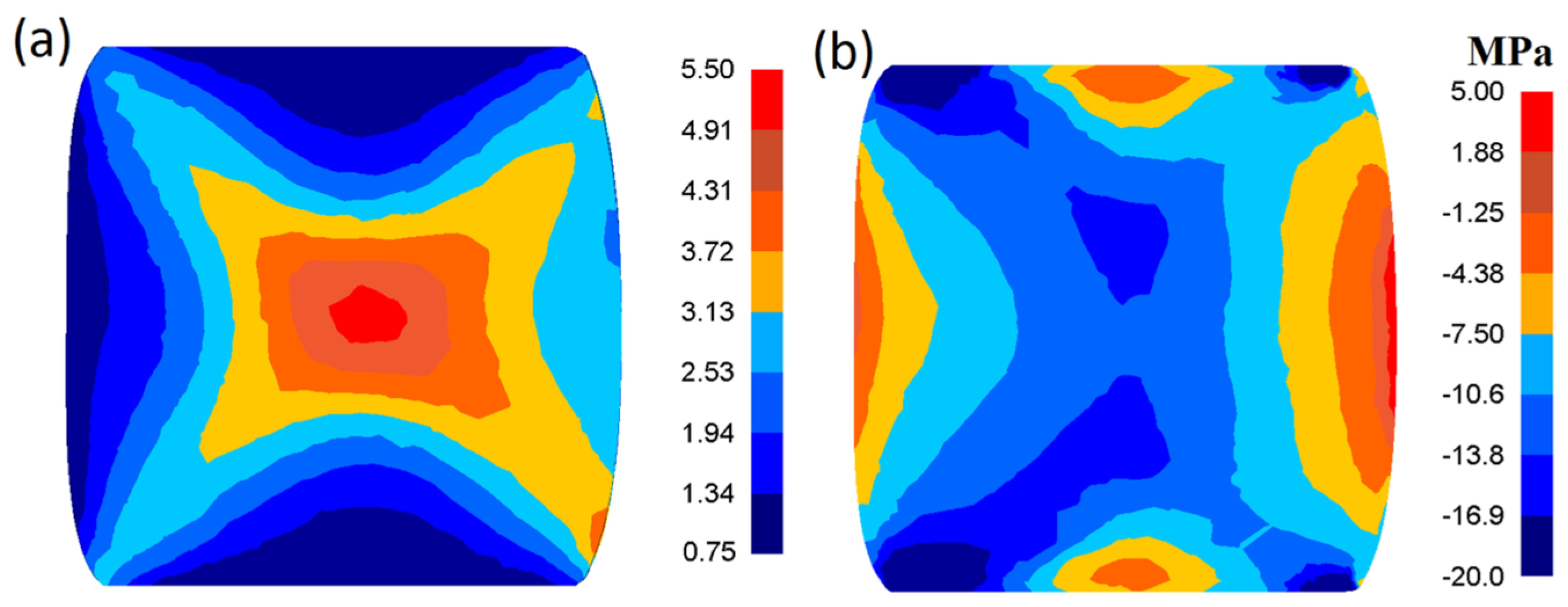
13]. The distribution of effective strain and mean stress on cross-section surfaces after the multi-pass cogging process on flat anvils with a forging ratio of K = 3.0 is shown in Figure 22. In the case of such a forging ratio in the central part of the cross section of a forging, large values of the effective strain, amounting to ε ¯ = 3.72–4.91 (Figure 22a), with compressive stresses dominating in this zone, were observed (Figure 22b). In the remaining zones, much smaller effective strain values were observed.
Figure 23 presents the correlation between the total reduction ratio and the damage factor for axial voids with different sizes (d0/D0 = 0.05, 0.10, and 0.20) in the course of a multi-pass cogging process in flat anvils. The applied Normalized Cockcroft and Latham Criterion (ψCL) presented different values depending on the size of the axial void. The highest values of ψCL were found for d0/D0 = 0.20, and they manifested a tendency to grow with the increase in the reduction ratio. The lowest values of ψCL were obtained for the smallest void (d0/D0 = 0.05). After the third pass (ε = 1.05), when the axial void underwent complete closure, the values of ψCL for the investigated sizes of void did not exceed the critical damage value and amounted to: 0.30, 0.42, and 0.48 for d0/D0 = 0.05, 0.10, and 0.20, respectively.
The calculated temperature after particular technological passes was compared with the experimental temperature measured at selected points on the surface of the deformed workpiece during the multi-pass cogging process in an integrated computer-controlled forging line with a 20 MPa hydraulic press (Figure 24). The measurement of temperature was performed with the use of a thermo-visual camera. The comparison showed a good agreement between the predicted and the experimental measurements.

4. Conclusions

This article reports the most important findings related to the study of the effect of hot cogging process parameters and shape of anvils on void closure efficiency (a novelty for forging technology). Void closure is an important scientific and technical problem, which requires a new complex methodology to eliminate voids. In this study, new forgings systems were investigated in comparison with the cogging process in flat anvils. The influence of the different initial sizes of the axial void and of the shape of the tools, the analysis of the indices characterizing the void closure process in the consecutive passes, the state of stress and of strains around the void were determined quantitatively. The major results are summarized as follows:
(a) For the quantitative analysis of the closure of an axial void, the following indices were introduced: the relative void diameter ratio ( η d ), the void area ratio ( η A ), the relative void volume evolution ratio ( η V ), and the internal closure evaluation index (Q value). When η d , η A , and η V become 0, the axial void will be closed. The relative void volume evolution ratio ( η V ) was the first-order index during the multi-stage void closure process, when the workpiece is rotated between each forming stage. In the course of the multi-pass cogging process of an ingot on flat anvils, the complete closure of an axial void was ascertained when the internal void closure evaluation index Q was equal to 0.85.
Furthermore, for the purpose of the assessment of the void closure process, the effective strain and the hydrostatic stress around the void, the stress triaxiality ( σ m / σ ¯ ), and the critical reduction ratio were determined. The effective strain and the hydrostatic stress in the region surrounding the void were very effective parameters which dominated the closure of voids during cogging. The complete closure of an axial void occurred ( η V = 0) when the effective strain around it reached the values of 1.20, 1.60, and 2.0 for the V-shaped anvils, the assembly of three radial anvils, and the flat anvils, respectively.
The state of stress around an existing void significantly influenced the process of its evolution. The absence of tensile stress in the axial workpiece zone was observed in V-shaped anvils and in the assembly of three radial anvils. In the cogging process on flat anvils, compressive stress in the central part of the forging was observed in the third pass. All differentially sized axial voids, commencing with the third pass, underwent deformation in the presence of compressive stresses (the stress triaxiality reached the values of −0.9).
The complete closure of all three differentially sized axial voids (d0/D0 = 0.05, 0.10, 0.20) occurred when the critical reduction ratio amounted to 0.35 (after the first pass), 1.05, and 1.05 (after the third pass) for the V-shaped anvils, the assembly of three radial anvils, and the flat anvils, respectively.
In the practice of forging, a very important parameter in the assessment of the internal quality of forgings is the minimum critical forging ratio. In order to ensure that all voids are eliminated, a critical forging ratio of K = 3.0 is recommended. In the case of such a forging ratio in the central part of a forging, large values of the effective strain amounting to ε ¯ = 3.72–4.91 (on flat anvils, K = 3.0), with compressive stresses dominating in this zone, were observed.
(b) V-shaped anvils (α = 130° × 130°) were found to be the most effective in the void closure process in the case of an axial void with different sizes, in comparison with the other anvils. Flat anvils were found to be the least effective in the void closure process. The efficiency of the assembly of three radial anvils in the void closure process was significantly lower than the efficiency of V-shaped anvils, but their greatest asset was a highly uniformity of the effective strain distribution in the deformation zone, accompanied by the absence of tensile stresses in the axial zone of the workpiece.
(c) On the basis of the Cockcroft–Latham criterion, the ductile damage model was developed for predicting the formation of cracks during the multi-pass cogging process in flat anvils. The effect of the size and the effect of the total reduction ratio and deformation temperature on the value of the ψCL criterion were examined. After the complete closure of an axial void, the values of ψCL did not exceed the critical damage value.

Funding

This research received no external funding.

Conflicts of Interest

The authors declare no conflicts of interest.

References

  1. Lin, Y.C.; Liu, Y.X.; Liu, G.; Chen, M.S.; Huang, Y.C. Prediction of Ductile Fracture Behaviors for 42CrMo Steel at Elevated Temperatures. J. Mater. Eng. Perform. 2015, 24, 221–228. [Google Scholar] [CrossRef]
  2. Xin, R.; Ma, Q.; Li, W. Microstructure and mechanical properties of internal crack healing in a low carbon steel. Mater. Sci. Eng. A 2016, 662, 65–71. [Google Scholar] [CrossRef]
  3. Wang, Y.-Z.; He, X.-H.; Li, J.; Zhou, C.-Y.; Miao, X.-T.; Yu, Q. Experimental and numerical investigation on fracture behavior of CTS specimen under I-II mixed mode loading. Eur. J. Mech. - A/Solids 2018, 72, 235–244. [Google Scholar] [CrossRef]
  4. Di, Y.A.O.; Lixun, C.A.I.; Chen, B.A.O. A New Fracture Criterion for Ductile Materials Based on a Finite Element Aided Testing Method. Mater. Sci. Eng. A 2016, 673, 633–647. [Google Scholar] [CrossRef]
  5. Liu, Z.G.; Wong, W.H.; Guo, T.F. Void behaviors from low to high triaxialities: Transition from void collapse to void coalescence. Int. J. Plast. 2016, 84, 183–202. [Google Scholar] [CrossRef]
  6. Cao, T.S.; Mazière, M.; Danas, K.; Besson, J. A model for ductile damage prediction at low stress triaxialities incorporating void shape change and void rotation. Int. J. Solids Struct. 2015, 63, 240–263. [Google Scholar] [CrossRef]
  7. Wang, B.; Zhang, J.; Xiao, C.; Song, W.; Wang, S. Analysis of the evolution behavior of voids during the hot rolling process of medium plates. J. Mater. Process. Technol. 2015, 221, 121–127. [Google Scholar] [CrossRef]
  8. Lee, Y.S.; Lee, S.U.; Van Tyne, C.J.; Joo, B.D.; Moon, Y.H. Internal void closure during the forging of large cast ingots using a simulation approach. J. Mater. Process. Technol. 2011, 211, 1136–1145. [Google Scholar] [CrossRef]
  9. Faini, F.; Attanasio, A.; Ceretti, E. Experimental and FE analysis of void closure in hot rolling of stainless steel. J. Mater. Process. Technol. 2018, 259, 235–242. [Google Scholar] [CrossRef]
  10. Chen, K.; Yang, Y.; Shao, G.; Liu, K. Strain function analysis method for void closure in the forging process of the large-sized steel ingot. Comput. Mater. Sci. 2012, 51, 72–77. [Google Scholar] [CrossRef]
  11. Chen, K.; Liu, K.; Chen, H.; Yang, Y. A criterion for void closure in the porous model during the forging of steel ingot and its application. Comput. Mater. Sci. 2014, 91, 303–309. [Google Scholar] [CrossRef]
  12. Kakimoto, H.; Arikawa, T.; Takahashi, Y.; Tanaka, T.; Imaida, Y. Development of forging process design to close internal voids. J. Mater. Process. Technol. 2010, 210, 415–422. [Google Scholar] [CrossRef]
  13. Zhang, L.; Shen, W.; Zhang, C.; Xu, Q.; Cui, Y. Numerical simulation of different types of voids closure in large continuous casting billet during multi-pass stretching process. Procedia Eng. 2017, 207, 532–537. [Google Scholar] [CrossRef]
  14. Saby, M.; Bernacki, M.; Roux, E.; Bouchard, P.O. Three-dimensional analysis of real void closure at the meso-scale during hot metal forming processes. Comput. Mater. Sci. 2013, 77, 194–201. [Google Scholar] [CrossRef]
  15. Chen, M.S.; Lin, Y.C.; Chen, K.H. Evolution of elliptic-cylindrical and circular-cylindrical voids inside power-law viscous solids. Int. J. Plast. 2014, 53, 206–227. [Google Scholar] [CrossRef]
  16. Feng, C.; Cui, Z. A 3-D model for void evolution in viscous materials under large compressive deformation. Int. J. Plast. 2015, 74, 192–212. [Google Scholar] [CrossRef]
  17. Feng, C.; Cui, Z.; Liu, M.; Shang, X.; Sui, D.; Liu, J. Investigation on the void closure efficiency in cogging processes of the large ingot by using a 3-D void evolution model. J. Mater. Process. Technol. 2016, 237, 371–385. [Google Scholar] [CrossRef]
  18. Wang, M.; Li, D.; Wang, F.; Zang, X.; Li, X.; Xiao, H.; Du, F.; Zhang, F.C.; Jiang, Z. Analysis of laminated crack defect in the upsetting process of heavy disk-shaped forgings. Eng. Fail. Anal. 2016, 59, 197–210. [Google Scholar] [CrossRef] [Green Version]
  19. Lee, J.; Kim, S.J.; Park, H.; Bong, H.J.; Kim, D. Metal plasticity and ductile fracture modeling for cast aluminum alloy parts. J. Mater. Process. Technol. 2018, 255, 584–595. [Google Scholar] [CrossRef]
  20. Li, H.F.; Wang, S.G.; Zhang, P.; Qu, R.T.; Zhang, Z.F. Crack propagation mechanisms of AISI 4340 steels with different strength and toughness. Mater. Sci. Eng. A 2018, 729, 130–140. [Google Scholar] [CrossRef]
  21. Nielsen, C.V.; Zhang, W.; Alves, L.M.; Bay, N.; Martins, P.A.F. Modeling of Thermo-Electro Mechanical Manufacturing Processes; Springer: New York, NY, USA, 2013; Available online: http://dx.doi.org/10.1007/978-1-4471-4643-8 (accessed on January 2013).
Figure 1. Schematic of the mesh for the finite-element model and the initial void, unit: mm.
Metals 09 00538 g001
Figure 2. Distribution of internal discontinuities at the center of the ingot.
Metals 09 00538 g002
Figure 3. The void closure process during forging in V-shaped anvils (130° × 130°) at the reduction ratios of (a) 0; (b) 0.10; (c) 0.16; (d) 0.22; (e) 0.29; (f) 0.35.
Metals 09 00538 g003
Figure 4. Correlation of flow stress and strain with temperature for two selected strain rates: 2.5 s−1 (a) and 3.5 s−1 (b).
Metals 09 00538 g004
Figure 5. The experimental and numerical computation model for the cogging process: (a) shape and size of the introduced initial void (d0/D0 = 0.05, 0.10 and 0.20, l0 = 10 mm), (b) geometrical model of the anvils and the deformed billet, (c) hitting sequence of the cogging process (l/wd = 0.70), (d) schematic diagram of the technological passes.
Metals 09 00538 g005
Figure 6. Shape of the anvils: (a) flat (rk = 20 mm, B = 200 mm), (b) V-shaped (α = 130° × 130°, Rw = 28 mm), (c) assembly of three-radial (R = 32 mm, r = 26 mm, α = 135°).
Metals 09 00538 g006
Figure 7. Set of anvils for experimental investigations: (a) flat, (b) V-shaped (α = 130° × 130°), (c) assembly of three-radial.
Metals 09 00538 g007
Figure 8. Distribution of effective strain (A) and mean stress (B) on the surface of the cross section during forging on flat anvils (d0/D0 = 0.20): (a) after pass 1, (b) after pass 2, (c) after pass 3.
Metals 09 00538 g008
Figure 9. Distribution of effective strain (A) and mean stress (B) on the surface of the cross section of a forging deformed on V-shaped anvils (α = 130° × 130°, d0/D0 = 0.20): (a) during pass 1 (ε = 0.22), (b) after pass 1.
Metals 09 00538 g009
Figure 10. Distribution of effective strain (A) and mean stress (B) on the surface of the cross section of a forging deformed in the assembly of three radial anvils (d0/D0 = 0.20): (a) during pass 3 (ε = 0.90), (b) after pass 3.
Metals 09 00538 g010
Figure 11. Change in the height and width of the axial voids at different passes during deformation on flat anvils: (a) FEM simulation, (b) laboratory experimentation.
Metals 09 00538 g011
Figure 12. Change in the void area ratio at different passes during deformation on flat anvils: (a) FEM simulation, (b) laboratory experimentation.
Metals 09 00538 g012
Figure 13. Correlation between relative void diameter ratio (ηd) and effective strain for the different sizes of void deformed with different tools.
Metals 09 00538 g013
Figure 14. Comparison of predicted and experimental results of ηd after cogging with different anvils: (a) flat, (b) V-shaped, (c) assembly of three radial anvils.
Metals 09 00538 g014
Figure 15. View of a macro-section forged in different anvils: (a) view of the initial voids, (b) after pass 3 in flat anvils (the voids are closed), (c) after pass 1 in V-shaped anvils (α = 130° × 130°), (the voids are closed), (d) after pass 3 in the assembly of three radial anvils and finish in flat anvils (the voids are closed).
Metals 09 00538 g015
Figure 16. Correlation between the relative void volume evolution ratio and effective strain for the different sizes of void deformed in different anvils.
Metals 09 00538 g016
Figure 17. Comparison of predicted and experimental results of the relative void volume evolution ratio (ηV) as a function of the reduction ratio during forging in different anvils.
Metals 09 00538 g017
Figure 18. Comparisons between the simulated (a) and experimental (b) results (effective strain) of X40CrMoV511 steel deformed in V-shaped anvils (α = 130° × 130°), feed rate 0.75, reduction ratio 0.70.
Metals 09 00538 g018
Figure 19. Shape and sizes of an axial void for the multi-pass cogging process on flat anvils (d0/D0 = 0.05, 0.10, and 0.20, l0 = 100 mm).
Metals 09 00538 g019
Figure 20. Correlation of the stress triaxiality (a) and effective strain (b) as a function of the reduction ratio during the multi-pass cogging process on flat anvils (forging ratio K = 3.0).
Metals 09 00538 g020
Figure 21. Correlation between the void closure evaluation index and the reduction ratio for different sizes of void during the multi-pass cogging process on flat anvils.
Metals 09 00538 g021
Figure 22. Distribution of effective strain (a) and mean stress (b) on the surface of the cross section of forging after the multi-pass cogging process on flat anvils (K = 3.0).
Metals 09 00538 g022
Figure 23. Correlation between the total reduction ratio and the damage factor during the multi-pass cogging process on flat anvils (K = 3.0).
Metals 09 00538 g023
Figure 24. Comparison between calculated and measured temperatures as a function of the total reduction ratio during the multi-pass cogging process on flat anvils (K = 3.0).
Metals 09 00538 g024

