Article

A Hot Cracking on Dissimilar Metal Weld between A106Gr.B and A312 TP316L with Buttering ERNiCr-3

School of Aerospace and Mechanical Engineering, Korea Aerospace University, 76 Hanggongdaehang-ro, Deokyang-gu, Goyang-si 10540, Korea
Metals 2019, 9(5), 533; https://doi.org/10.3390/met9050533
Submission received: 18 April 2019 / Revised: 4 May 2019 / Accepted: 7 May 2019 / Published: 8 May 2019

Abstract

:
When designing piping systems for various industrial facilities, carbon steel and stainless steel are widely being used. In order to satisfy design requirements in the piping systems, the two different materials are often welded in various cases. Therefore, for quality assurance, it is necessary to understand mechanical and metallurgical properties of dissimilar metal welds thoroughly. In this study, dissimilar metal welds of stainless and carbon steels were produced through the gas tungsten arc welding (GTAW) process. In the middle of the dissimilar weld, buttering welding and butt welding were manufactured using filler wires of ERNiCr-3 and ER316L. The chemical composition of the dissimilar metal weld was analyzed. Tensile test, bending test, and hardness test were additionally performed. The microstructures of the dissimilar metal weld were investigated to analyze the cracks found during the tensile test and the bending test. The metallographic behavior was analyzed in the vicinity of the cracks. The mechanism and cause of the cracks in the dissimilar metal weld were identified. As a result, the precipitates of complex carbide types were observed in segregation bands.

1. Introduction

When designing piping systems for various industrial facilities, materials that satisfy optimal performance are selected in consideration of design conditions such as durability, corrosion resistance, economy, and productivity [1,2,3,4]. Stainless steel is usually used in the part where corrosion resistance is required, and carbon steel is used in the part where corrosion resistance is not required, depending on the operational environment. If a piping system is composed of different steel types depending on operational environment and design conditions, the joints of dissimilar metals are essential for the fabrication of the piping system. The joints are mainly manufactured by welding.
Compared to the weld between same materials, the dissimilar metal weld of carbon and stainless steels can cause weld defects and corrosion, due to difference in stress, carbon migration, and weld discontinuities [5]. In order to prevent weld defects and corrosion for the sound welds of dissimilar metal, it is important to optimize welding conditions and to select proper filler materials based on the metallurgical understanding.
The main problem in the dissimilar metal welds of carbon steel and stainless steel is that carbon contained in carbon steel is diluted with stainless steel and combined with Cr of stainless steel along grain boundary. As a result of this phenomenon, a carbide of Cr23C6 is created [6]. When Cr23C6 is formed, a Cr-depleted zone is formed around the welded joint, which causes strength degradation of the welded joint, weld cracks, and intergranular corrosion [7]. This phenomenon is called the grain boundary sensitization.
In order to prevent the sensitization and the dilution of carbon, a buttering with Ni-base alloy filler metal on the groove surface of the carbon steel part is produced. The buttering is a method to add a buffer-layer on the groove surface before dissimilar welding. The Ni-base alloy filler metal contains Nb or Ti which easily form carbides than Cr, thus controlling the formation of Cr23C6 [8]. In addition, the Ni-base alloy filler has a thermal expansion coefficient of 13.3 × 10⁻⁶ K−1 that is intermediate between carbon steel and stainless steel. Therefore, a uniform strain variation between the dissimilar weld materials is possible in case of the thermal stress change of the weldment. For the above reasons, the Ni-base alloy filler metal is mainly used for buttering in the dissimilar joints.
Research on dissimilar metal and buttering welds has been continuously conducted. Most studies have focused on the mechanical properties of the weldment and the microstructures created by fusion, melting, and solidification during welding processes [2,4,9,10,11,12,13,14,15,16]. Through literature review, C. D. Lundin [5] explained that the main cause of the damage generated in the dissimilar metal welds is the difference in the stress/strain of welds, induced by carbon migration and welding heat. Additionally, in order to analyze the damage, the author also guided various methods such as microstructure observation, chemical composition analysis, tensile test, bending test, fatigue test, and nondestructive test.
There are some studies on stress corrosion cracking (SCC), creep characterization, and hot cracking to analyze the defects mechanism in the dissimilar metal welds.
As a study on SCC in dissimilar metal weld, Chung et al. [17] examined the microstructure of dissimilar welds of Alloy 52 and A508 to determine the cause of SCC. Ductility loss of the dissimilar metal weld was determined to be the cause of SCC. The parameter related to the ductility loss was presented and verified by experiment results. Li et al. [18] produced dissimilar metal weld of low alloy steel and stainless steel to simulate SCC and analyze the microstructure of the weldment. They claimed that SCC occurred in the interface and transition zone of the dissimilar welds. They also presented that the cause of SCC was the microstructural changes and the chemical composition variations due to dilution effect in welding.
Studies on the creep characteristics of dissimilar metal weld have been conducted mainly on two points: the mechanical properties of specimens generated by creep and the microstructures evolved at high temperatures. In order to identify cause and mechanism of Type IV cracks, Shin et al. [19,20] produced dissimilar welds of Inconel 740H and TP316H through shielded metal arc welding (SMAW) process. Creep tests were carried out using the dissimilar welds. The microstructure analysis of the welds and the investigation of the fracture surface after creep were carried out as well. During the creep test, cavities which were not found at room temperature were observed in the dissimilar weld. NbC and Laves, which are secondary phase, were observed near the cavities. It was claimed that the Nb-rich segregation band and Laves phase existing in grain boundary provided a preferred place for the void formation.
As studies on hot cracking in dissimilar metal weld, Wu et al. [21] conducted Varestraint crack test using Inconel filler 52, Inconel filler 82, and base metal of Alloy 690. They evaluated susceptibility of hot cracking. Inconel filler 82 was consequently proven to have a higher hot cracking susceptibility than that of Inconel filler 52, when it was welded with Alloy 690. Characteristics of the hot cracking were also explained by scanning electron microscope (SEM) and energy dispersive X-ray spectroscopy (EDS) analysis. The cracks started from the weld metal to the heat-affected zone (HAZ) and then progressed along the grain boundary. The causes of cracks were found to be the wider melting/solidification temperature differential and the decrease of the melting points by segregation of chemical components such as Si, Nb, Ca from the Inconel filler 82 in the grain boundary and crack tip.
Shah et al. [22] produced dissimilar metal weld of Inconel 617 and AISI 310 stainless steel using three sorts of filler metals which are Inconel 617, Inconel 82, and 310 austenitic stainless, through gas tungsten arc welding (GTAW) process. In this study, the microstructure of the weld showed cracks in the unmixed zone where a 310 stainless steel filler metal was used. The observed cracks were considered as hot cracks due to the Cu precipitates formed along the grain boundaries. Ko et al. [23] analyzed the causes of the hot cracks in the dissimilar welds of Alloy 690 filler metals rods and STS308L clad materials. The NbC and Laves phases were distinguished by SEM and EDS analysis. As a result, the Laves phase formed between the grains was considered as a main factor of the cracks.
Several studies were conducted on the dissimilar weld of stainless steel and carbon steel. However, there is no research on the dissimilar metal pipe weld of ASTM A106Gr.B and ASTM A312 TP316L with a buttering part. The buttering weld was produced with ERNiCr-3 through the GTAW process. Tensile test, bending test, and hardness test were conducted on the buttering weld and the main weld metal. The microstructures of the welds were investigated through optical microscope (OM) and scanning electron microscopy/energy dispersive x-ray spectroscopy (SEM-EDS) in order to study the cracks found in the tests and the metallurgical behavior of the cracked welds. The chemical compositions of welds, base metal, and cracks were mapped using a field emission electron probe micro analyzer (FE-EPMA). The purpose of the above sequences was to identify the mechanism of the cracks found in the weldment.

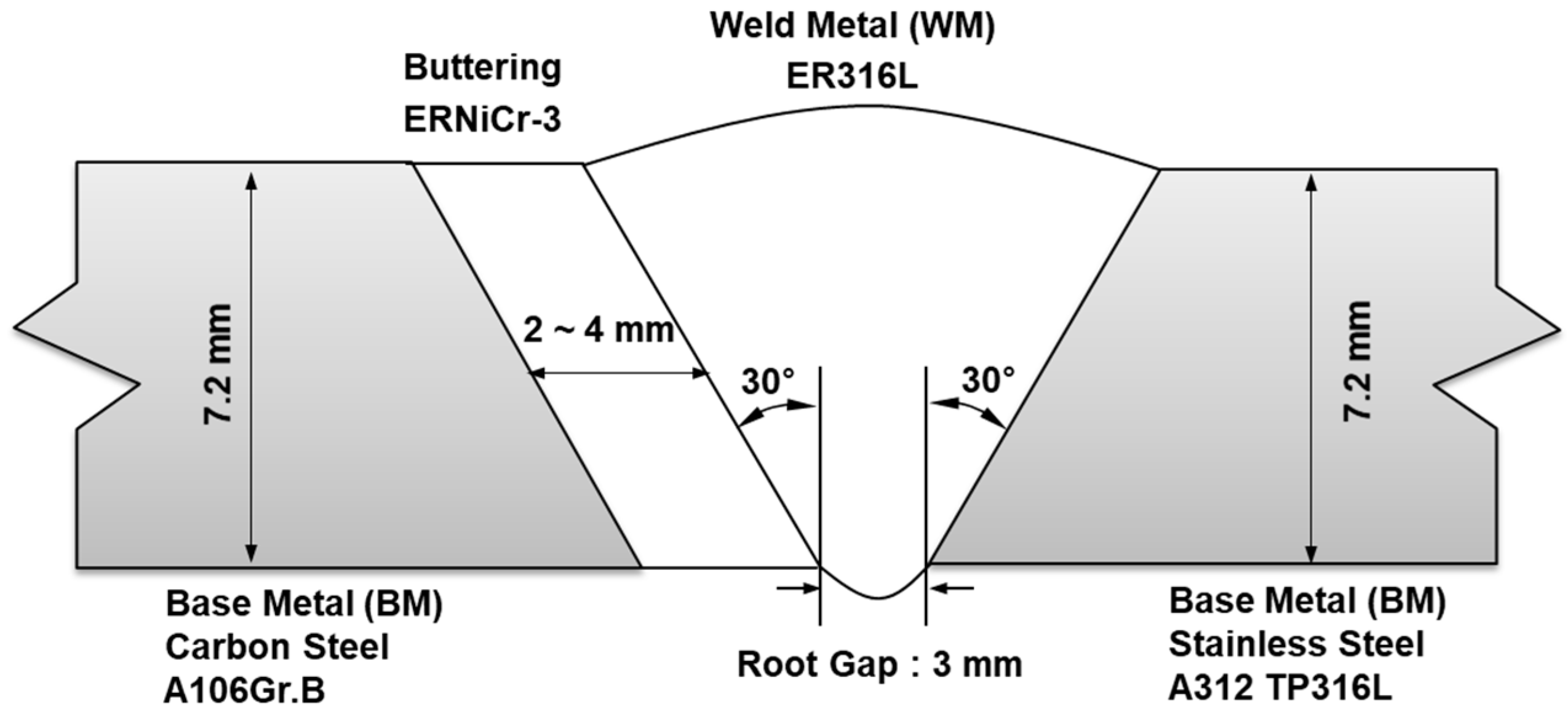
2. Experimental Procedures

The base metals used in this study are carbon steel A106Gr.B and hot rolled stainless steel A312 TP316L. The pipes manufactured using the base metals have an outer diameter of 168.5 mm, an inner diameter of 153.8 mm, and a thickness of 7.2 mm. The A312 TP316L had been water-cooled using solution heat treatment at the initial temperature of the minimum 1040 °C. The chemical compositions of the base metals and filler materials are shown in Table 1. Buttering weld and butt weld called weld metal (WM) in this paper were produced as shown in Figure 1, under the welding conditions listed in Table 2 and Table 3. The shape of the dissimilar weld joint is single beveled V-groove. The buttering welding was performed with the GTAW process using an ERNiCr-3 filler metal with a diameter of 2.4 mm. ERNiCr-3 is commonly used for welding austenitic alloys with high thermal expansion coefficient and ferritic steels with low thermal expansion coefficient. Root pass welding and multi-pass welding were performed by GTAW process for this dissimilar welding.
After welding, various tests which satisfy international standards were performed. According to ASME BPVC Sex-IX QW 150, the samples for the tensile test were produced by machining the dissimilar welds. The thickness of the specimen was 7.2 mm, same with the pipe thickness. The width of the specimen was 20 mm and the total length of the specimen was 250 mm. The gage length was 50 mm. Uniaxial tensile tests were conducted using a universal testing machine (Z1200 of Zwick Roell company, Germany). According to ASME BPVC Sex-IX QW 160, the bending test was conducted as well. The hardness of the dissimilar weld was measured with a micro Vickers hardness tester (HV-114, Mitutoyo, Japan). The test was performed at room temperature. The used loading for the hardness test was 98N.
In order to observe microstructures, the specimens of the dissimilar welds were machined and polished. The specimens were etched with an etchant of 65 mL nitric acid, 18 mL acetic acid, and 17 mL distilled water. The optical microscope (OM) manufactured by WBS-600AN (Leica microsystems, Wetzlar, Germany) was used for the analysis of the microstructure and cracks. Furthermore, a mapping of chemical components was performed using the SEM by the QUANTA 600F equipment (FEI, OR, USA). The FE-SEM 7200F manufactured by JEOL (Tokyo, Japan) used for FE-EPMA.

3. Results

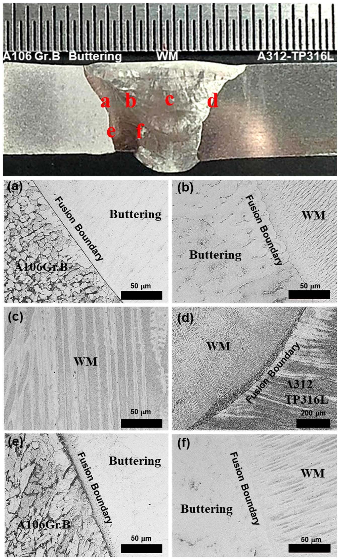
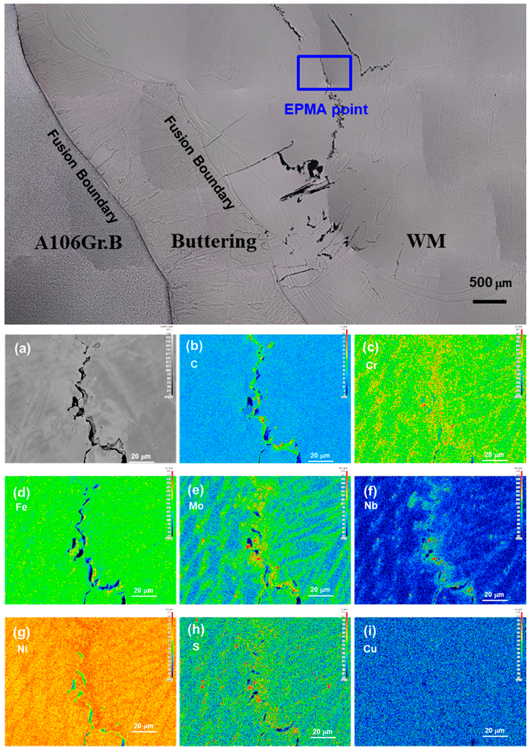
3.1. Microstructural Features

Figure 2 shows the optical micrographs of the dissimilar welds produced under the conditions listed in Table 2 and Table 3. As listed in Table 2, the buttering consists of multi-layer welds of five passes and, as shown in Table 3, the butt weld consists of multi-layer welds of six passes. There are three fusion boundaries and heat-affected zones (HAZ), respectively, in the dissimilar metal welds. From the left to the right, the cross-sectional photograph of dissimilar welds shows the base metal (BM) of the A106Gr.B carbon steel, the buttering weld by the ERNiCr-3 filler metal, the weld metal (WM) by the ER316L filler metal, and a base metal (BM) of the A312 TP316L. As shown in Figure 2a, A106Gr.B was composed of ferrite and pearlite microstructures. At the fusion boundary formed between the A106Gr.B and the buttering welds, coarse grained structure in the HAZ of the base metal, compared with the original microstructure of the base metal, was observed as shown in Figure 2a. In the buttering welds manufactured by the ERNiCr-3 filler metal, austenite structure can be found as shown in Figure 2b.
In addition, in the buttering welds, fine inclusions were found at inter-dendritic region and grain boundary. When the dissimilar metal is welded to ER316L with butt joint, Figure 2b shows that the grains of the WM epitaxially grew along the grains near the fusion boundary. Figure 2c shows the microstructure of the butt weld named as WM. In this figure, the columnar dendritic structure of the austenite phase is well developed. This might result from the high solidification rate. According to the chemical composition analysis of the filler metal, the ratio of the Cr(eq)/Ni(eq) was 1.585. In case of the ratio, the high solidification rate can cause the austenite mode or the ferrite–austenite mode [24].
It was observed that the microstructure of the A106Gr.B in Figure 2e is coarser than that of the A106Gr.B in Figure 2a. This is due to the increased temperature of the A106Gr.B by the multi-pass buttering welds. As listed in Table 2, before the buttering welds, the area of the A106Gr.B depicted in Figure 2e had the temperature of 22 °C, which is lower than that in Figure 2a, which was 116 °C. This indicates that the heat was accumulated during the multi-pass welds. Therefore, the grain size shown in Figure 2e became larger by the retained heat by the multi-pass buttering welds. This is in line with the thicker black carbide layer with 5 to 10 µm near the fusion boundary, as shown in Figure 2e. In other words, the heat accumulated by multi-pass buttering welds result in the increased carbon diffusion near the fusion boundary. The thick carbide layer is not observed in Figure 2a.
No crack or defect was found in the microstructure of the BM and the buttering welds. However, since voids and cracks were observed near the fusion boundary between the buttering weld and the WM and between the WM and the A312 TP316L base metal. Additional microstructure observations and analyses were conducted to figure out the characteristic of cracks formed in the WM.

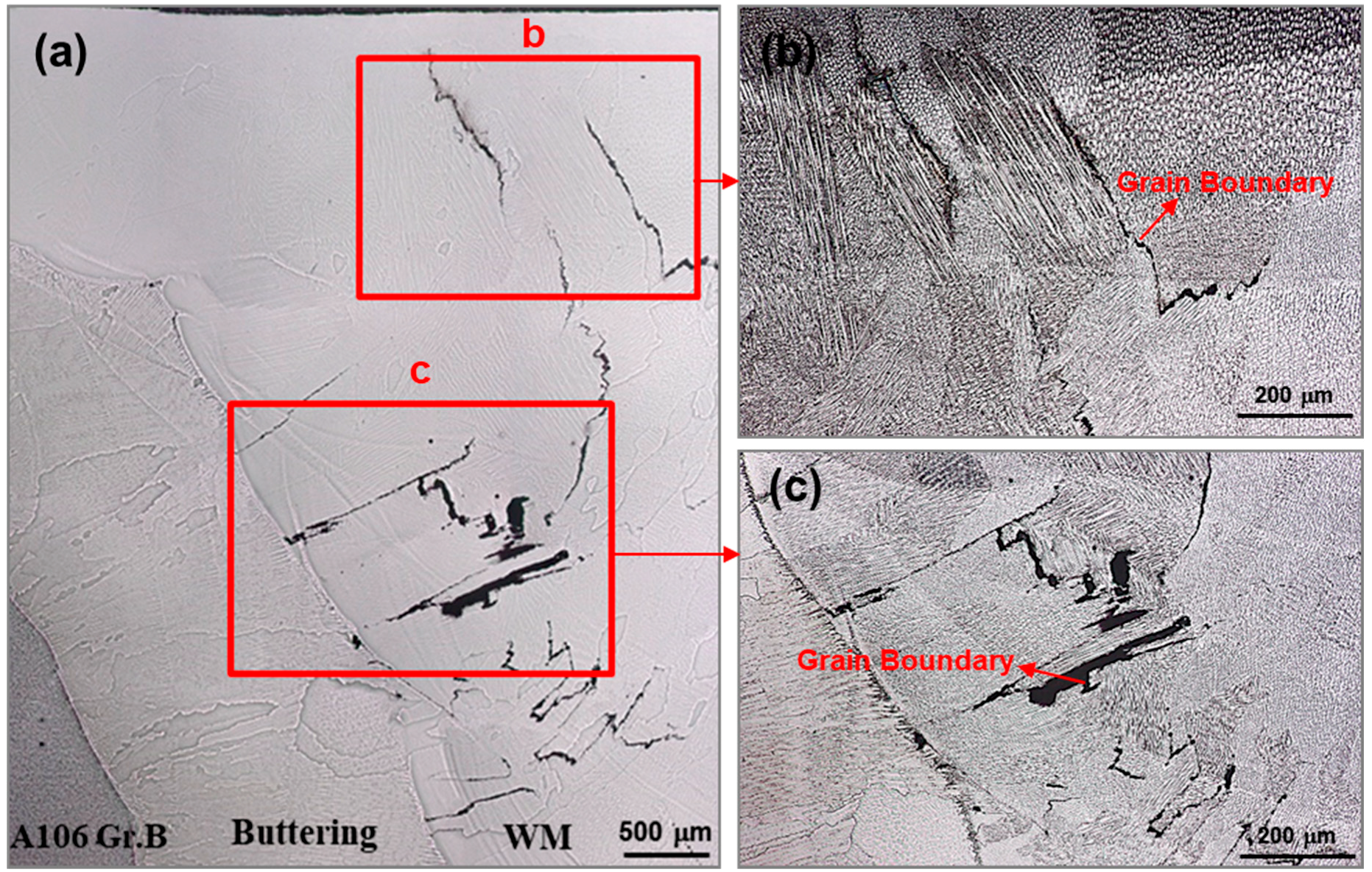
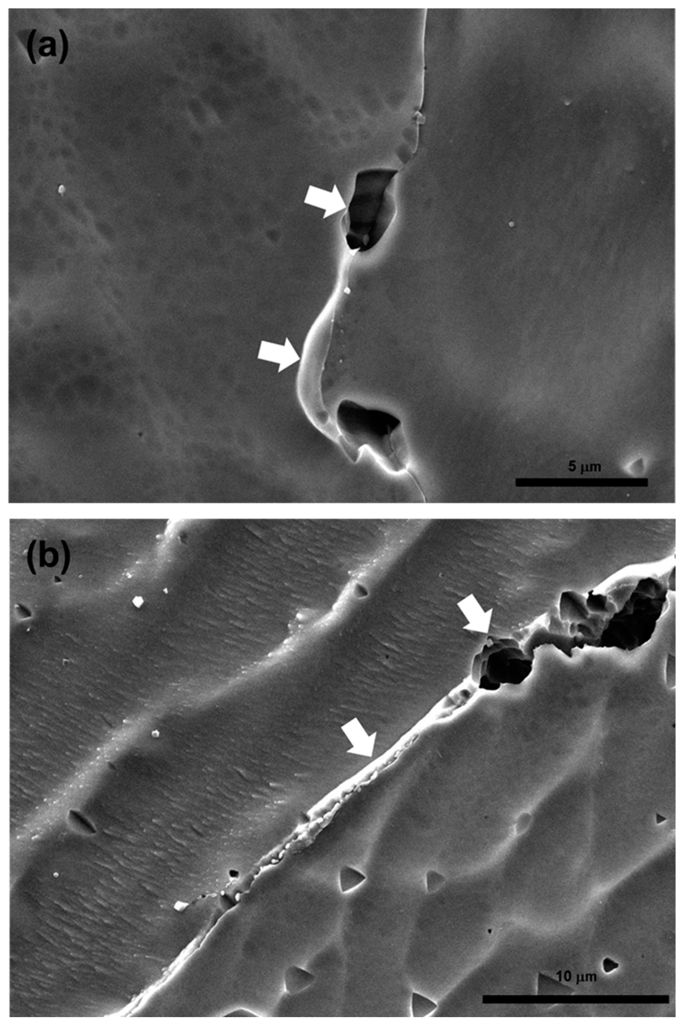
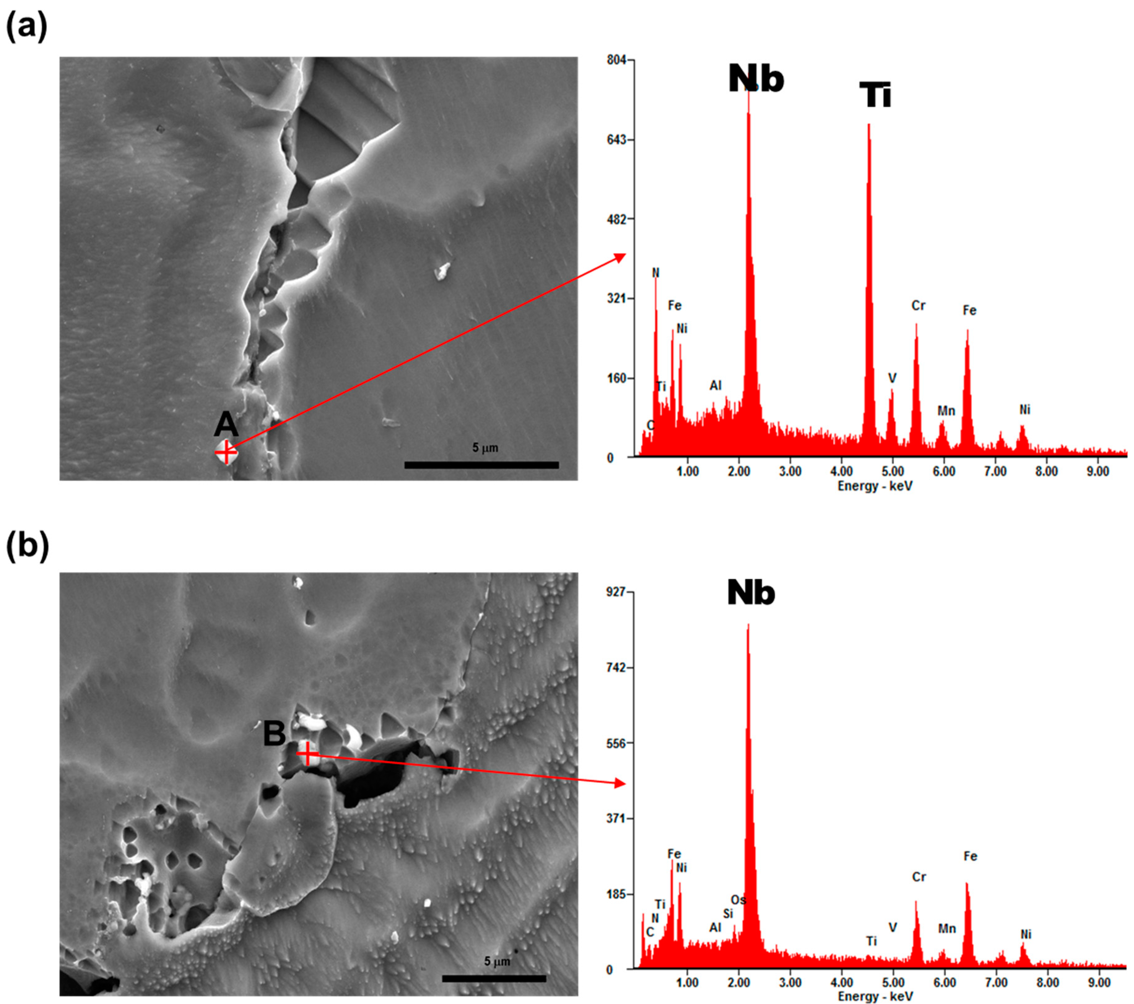
3.2. Characteristics and Mechanism of Cracks in the Dissimilar Welds

Figure 3 shows the microstructure of the cracks formed in the butt welds. Figure 3a was a picture combined with several OM pictures showing the buttering and the WM. Figure 3a was taken before etching. As shown in Figure 3b, the cracks were formed along the grain boundaries. Figure 3c also shows that cracks occurred along the grain boundary and propagated to the fusion boundary between the buttering and the WM.
In order to investigate the cracks, SEM was used as shown in Figure 4. Figure 4a is a combined picture of several OM pictures. Figure 4b shows the cracks similar to those shown in Figure 3. Although the size of the cracks near A312 TP316L was smaller than the size of the cracks near the buttering fusion boundary, the common thing is that the crack occurred along the grain boundary as well. Figure 4c–e are SEM photographs with high magnification compared to Figure 4b. As shown in Figure 4c, it is observed that a segregation band exists along the crack surface. Figure 4c,d show the 1-μm-sized precipitates and voids produced along the grain boundary. The voids are connected with a crack. In Figure 4e, voids and fine precipitates were observed near cracks as well.
Figure 5 shows fractographies of the crack surface. Figure 5b shows an enlarged photograph of the area marked with a rectangular inset of Figure 5a. Figure 5c,d shows the enlarged area depicted in Figure 5b. Figure 5c,d show the smooth crack surface which is the typical shape of liquidation crack [21]. Dimples which can be often seen in ductile fracture were not observed.
Figure 6 shows elemental mapping images of the area containing cracks in the WM using FE-EPMA. The various chemical components such as C, Cr, Fe, Mo, Nb, Ni, Cr, and Cu were mapped as shown in Figure 6b–i. As a result, the carbon (C), niobium (Nb), and molybdenum (Mo) components are enriched along the propagated crack. In addition, it could be confirmed that the segregation bands were formed around the cracks. Sulfur (S), which can induce solidification cracks, was barely observed as a result of the mapping [25].
Figure 7 shows SEM micrographs and EDS spectra of the precipitates found near the crack in the WM. The weld pool was solidified below solidus temperature due to constitutional super cooling. This causes segregation, which formed precipitates in the inter-dendritic region [26]. As shown in Figure 7a, blocky precipitates were observed. At point A in Figure 7a, the chemical components of Nb, Ti, and C were most abundant except for that of Fe, Ni, and Cr, which are major components of the matrix, as shown in Table 4. The peak of N in EDS resulted from the nitric acid of the etchant because all the materials in this study have no nitrogen. The results of SEM-EDS analysis for the precipitates found in the voids are shown in Figure 7b and Table 5. At point B in Figure 7b, the chemical components of Nb and C were most abundant except for that of Fe, Ni, Cr, which are major components of the matrix, as shown in Table 5.
Figure 8a,b show voids observed along the cracks in the WM. The precipitate with a shape of an intergranular liquid film linking the voids was observed in Figure 8a. Figure 8b shows the liquid film-shaped precipitate in the crack as well. It is a prerequisite for liquidation crack that surfaces of cracks and voids are smooth and the formation of intergranular liquid film was found in grain boundary [27,28]. As a result, it was confirmed to the precipitate which is Nb-rich intermetallic compound or carbide in cracks along grain boundary. This is because of the dilution of the chemical components of the buttering welds. The components were moved by the molten metal flow generated during the multi-passes of the butt joint welding. It was confirmed that the same shape of liquidation cracking occurred due to the dilution of the buttering welds by multi-layer welding and mixed weld pool during butt joint welding.

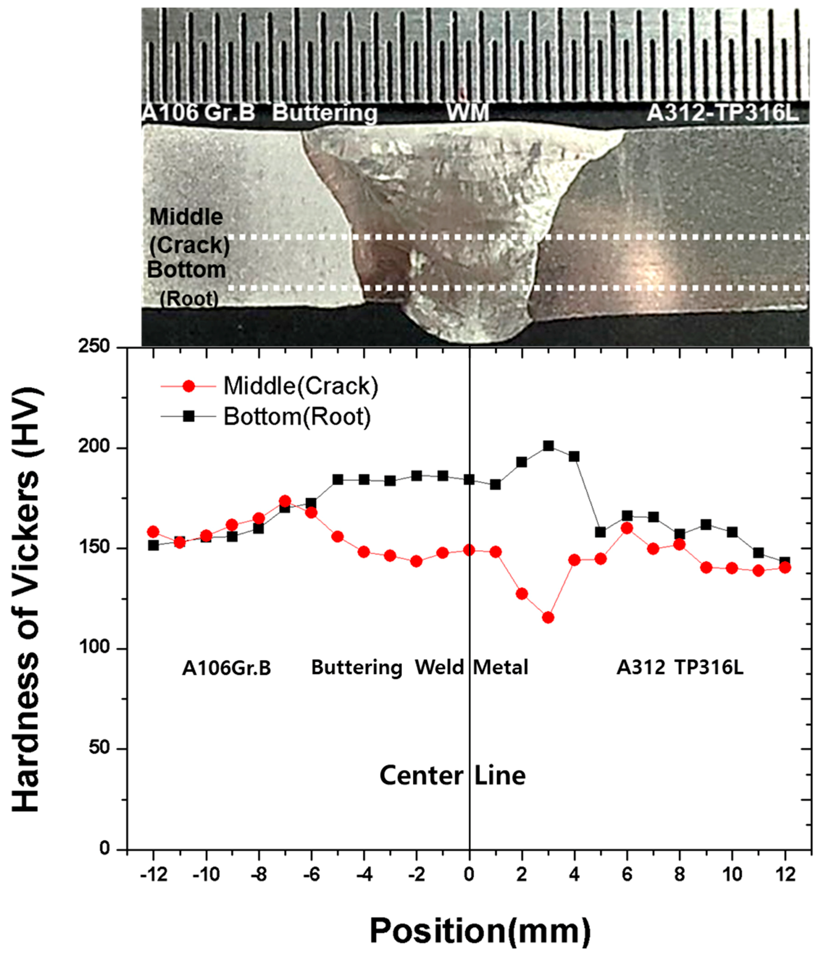
3.3. Mechanical Properties

According to tensile test results in mill certificate of the base metals and filler metals, filler metal ERNiCr-3 has the highest tensile strength compared to those of the base metal or filler metal ER316L, as shown in Table 6. Coarsened grain and crack formation in the WM and BM cause deterioration of the mechanical properties such as tensile strength reduction, hardness reduction, and cracks in the bending test.
Tensile test results of the dissimilar welded joints are listed in Table 7. Fracture occurred in the WM. The measured tensile strength was 415 MPa in case of Specimen 1 and 438 MPa in case of Specimen 2, respectively. The tensile strengths of the weldments were even lower than that of A106Gr.B, which is the smallest in Table 6. When welding same materials with a filler material that has a similar tensile stress with the base material, the fracture generally occurs in the heat-affected zone or the base metal. However, the mechanical behavior of dissimilar metal welds differs from that of weld between same metals. In this study, the specimens of the tensile tests were fractured in the WM where cracks had been formed.
The guided bend test results were summarized and listed in Table 8. A number of cracks which have a size of 2 to 5 mm were found in the face area, and several cracks which have a size of 2 to 10 mm in the root area were found after the bending test. All the cracks occurred in the WM.
Vickers hardness were measured at 1 mm intervals on middle and bottom parts in the BM, buttering, and the WM, respectively, as shown in Figure 9. The measured Vickers hardness was from 115 HV to 201 HV. The lowest hardness was measured at the location where cracks were formed in 3 mm of the middle part as depicted in the upper specimen picture of Figure 3. The maximum hardness at the bottom part was shown in the HAZ of the A312 TP316L base metal. The maximum hardness at the middle part (cracked part) was shown in the HAZ of A106Gr.B base metal. In the weldment, the hardness of the bottom part was higher than that of the middle part. The reason for the higher hardness of the weldment in the bottom part is that the cooling rate in the bottom part was faster than that in the middle part.

4. Discussion

As shown in Figure 6, the specific chemical components formed segregation bands in grain boundary after multi-layer welding. In particular, Nb tends to remain in the solution until the last moment of the solidification, due to its small distribution coefficient [29]. This phenomenon is known as constitutional liquation. When a filler metal including Nb such as ERNiCr-3 is used for welding, NbC, TiC, or Nb-rich Laves phase are crystallized by eutectic reaction in the final coagulated grain boundary and dendritic region [30,31].
In this study, the filler materials used for buttering welds and butt welds were ERNiCr-3 and ER316L, respectively. Especially, ERNiCr-3 contains 2.41 wt% of Nb with Ta and 0.37 wt% of Ti, as shown in Table 1. ERNiCr-3 is a Ni-base alloy filler metal, which is expected to have similar constitutional liquation process with Inconel 600 series in multi-layer welding. When the segregated liquid cools down, a eutectic reaction occurs. In other words, the liquid phase is transformed to austenite and carbide. The reverse transformation from austenite and carbide to liquid phase occurs along the grain boundary due to the reheating of the welded joint during multi-pass welding. These phenomena are repeated and this causes tensile stress variation in the grain boundary. In this study, the segregation band near the grain boundaries became liquefied due to the reheat during multi-layer welding. Tensile stress induced during the solidification formed cavities and cracks. The tensile stress was applied in the direction to the grain growth and coincided with the shape of the cracks observed.
Another noticeable point is the location of the cracks found in the WM, as shown in Figure 4. The cracks were located in the side which is far from the buttering welds. Only buttering welds had Nb among all materials used in this study. As shown in Figure 7, complex carbide such as NbC or TiC were formed in the crack area. This indicates that the buttering welds were partially diluted during multi-pass welding and the weld pool of the ER316L was mixing with the diluted materials.
Therefore, it is necessary to suppress the formation as much as possible to prevent cracks. In order to prevent cracks, the heat treatment would be carried out for complex carbides such as NbC or TiC and Laves phase to be sufficiently dissolved in the matrix. Another way is to give low heat input in the weldment for minimizing the tensile stress or strain.

5. Conclusions

In this study, dissimilar welds of general carbon steel, A106Gr.B, and austenitic stainless steel, A312 TP316L, were manufactured through GTAW process. The microstructure near the fusion boundary and cracks were observed and reviewed through OM, SEM, SEM-EDS, and FE-EPMA. Tensile tests and bending tests were conducted on the manufactured specimen. The causes and mechanisms of the produced cracks were identified through the microstructure analysis. The main conclusions are as follows.
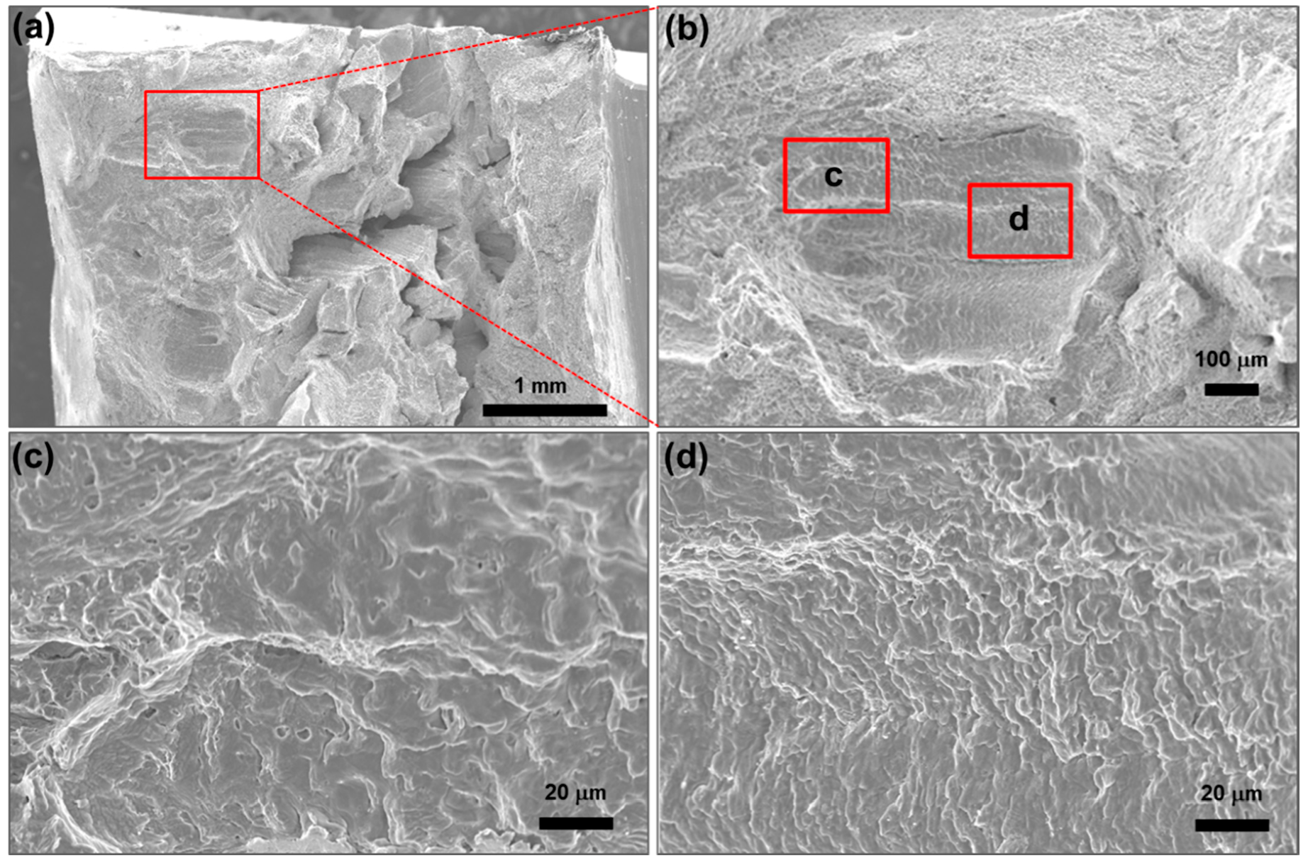
  • During the tensile test, a fracture of the dissimilar welds occurred in the WM, while a fracture of joining same materials normally occurs in a HAZ or BM. The fracture was caused by cracks formed in the WM. As cracks and voids were observed in the grain boundaries, the fracture is not a ductile fracture but considered as an intergranular fracture.
  • The cracked area was mainly located in the WM and in vicinity of the fusion boundary between the buttering and the WM. Due to the cracks, the results of the tensile test showed that the weldment has a lower tensile strength than those of base metal and filler metal. In the vicinity of the crack, the hardness was the lowest.
  • The secondary phase formed near the cracks was identified as NbC which is the main cause of liquidation cracking. As a result of SEM, SEM-EDS, and FE-EPMA, the complex carbide containing a large amount of Nb or Ti was confirmed on the crack surface. The repeated solidification and constitutional liquation occur in the segregated liquid area during multi-pass welding. In the solidification by the mixed weld pool, NbC or TiC was produced by the eutectic reaction. The tensile stress was produced by the solidification of the mixed weld pool and the constitutional liquation. The voids were formed in the grain boundaries because of the tensile stress. As a result, the continuous formation of the voids caused the cracks.

Acknowledgments

This work was supported by Korea Evaluation Institute of Industrial Technology (KEIT) grant funded by the Korea government (MOTIE) (No. 10062648).

Conflicts of Interest

The author declares no conflict of interest.

References

  1. Javadi, Y.; Ashoori, M. Sub-surface stress measurement of cross welds in a dissimilar welded pressure vessel. Mater. Des. 2015, 85, 82–90. [Google Scholar] [CrossRef]
  2. Cao, J.; Gong, Y.; Zhu, K.; Yang, Z.-G.; Luo, X.-M.; Gu, F.-M. Microstructure and mechanical properties of dissimilar materials joints between T92 martensitic and S304H austenitic steels. Mater. Des. 2011, 32, 2763–2770. [Google Scholar] [CrossRef]
  3. Rossini, M.; Spena, P.R.; Cortese, L.; Matteis, P.; Firrao, D. Investigation on dissimilar laser welding of advanced high strength steel sheets for the automotive industry. Mater. Sci. Eng. A Struct. Mater. 2015, 628, 288–296. [Google Scholar] [CrossRef]
  4. Rathod, D.W.; Singh, P.K.; Pandey, S.; Aravindan, S. Effect of buffer-layered buttering on microstructure and mechanical properties of dissimilar metal weld joints for nuclear plant application. Mater. Sci. Eng. A Struct. Mater. 2016, 666, 100–113. [Google Scholar] [CrossRef]
  5. Lundin, C. Dissimilar Metal Welds-Transition Joint Literature Review. Weld. J. 1982, 61, 58–63. [Google Scholar]
  6. Hall, E.L.; Briant, C.L. Chromium depletion in the vicinity of carbides in sensitized austenitic stainless steels. Metall. Mater. Trans. A 1984, 15, 793–811. [Google Scholar] [CrossRef]
  7. Tedmon, C.S.; Vermilyea, D.A.; Rosolowski, J.H. Intergranular Corrosion of Austenitic Stainless Steel. J. Electrochem. Soc. 1971, 118, 192–202. [Google Scholar] [CrossRef]
  8. Kou, S. Welding Metallurgy, 2nd ed.; A John Wiley & Sons Inc.: Hoboken, NJ, USA, 2003. [Google Scholar]
  9. Sireesha, M.; Shankar, V.; Albert, S.K.; Sundaresan, S. Microstructural features of dissimilar welds between 316LN austenitic stainless steel and alloy 800. Mater. Sci. Eng. A Struct. Mater. 2000, 292, 74–82. [Google Scholar] [CrossRef]
  10. Chen, Z.R.; Lu, Y.H.; Ding, X.F.; Shoji, T. Microstructural and hardness investigations on a dissimilar metal weld between low alloy steel and Alloy 82 weld metal. Mater. Charact. 2016, 121, 166–174. [Google Scholar] [CrossRef]
  11. Ramkumar, K.D.; Kumar, B.M.; Krishnan, M.G.; Dev, S.; Bhalodi, A.J.; Arivazhagan, N.; Narayanan, S. Studies on the weldability, microstructure and mechanical properties of activated flux TIG weldments of Inconel 718. Mater. Sci. Eng. A Struct. Mater. 2015, 639, 234–244. [Google Scholar] [CrossRef]
  12. Vidyarthy, R.S.; Kulkarni, A.; Dwivedi, D.K. Study of microstructure and mechanical property relationships of A-TIG welded P91–316L dissimilar steel joint. Mater. Sci. Eng. A Struct. Mater. 2017, 695, 249–257. [Google Scholar] [CrossRef]
  13. Kwon, S.I.; Bae, S.H.; Do, J.H.; Jo, C.Y.; Hong, H.U. Characterization of the Microstructures and the Cryogenic Mechanical Properties of Electron Beam Welded Inconel 718. Metall. Mater. Trans. A 2015, 47, 777–787. [Google Scholar] [CrossRef]
  14. Torkamany, M.J.; Tahamtan, S.; Sabbaghzadeh, J. Dissimilar welding of carbon steel to 5754 aluminum alloy by Nd:YAG pulsed laser. Mater. Des. 2010, 31, 458–465. [Google Scholar] [CrossRef]
  15. Pereira, A.; Cabrinha, A.; Rocha, F.; Fernandes, F.; Alves de Sousa, R.; Marques, P. metals Dissimilar Metals Laser Welding between DP1000 Steel and Aluminum Alloy 1050. Metals 2019, 9, 102. [Google Scholar] [CrossRef]
  16. Song, J.L.; Lin, S.B.; Yang, C.L.; Ma, G.C.; Liu, H. Spreading behavior and microstructure characteristics of dissimilar metals TIG welding–brazing of aluminum alloy to stainless steel. Mater. Sci. Eng. A. Struct. Mater. 2009, 509, 31–40. [Google Scholar] [CrossRef]
  17. Chung, W.-C.; Huang, J.-Y.; Tsay, L.-W.; Chen, C. Microstructure and Stress Corrosion Cracking Behavior of the Weld Metal in Alloy 52-A508 Dissimilar Welds. Mater. Trans. 2011, 52, 12–19. [Google Scholar] [CrossRef]
  18. Li, G.F.; Yuan, Y.F.; Lu, X. Microstructure and Stress Corrosion Cracking of Dissimilar Metal Weld 16MND5/309L/308L/Z2CND18-12N Used for Connecting Reactor Pressure Vessel to Piping in Nuclear Power Plants. Procedia. Eng. 2015, 130, 1572–1579. [Google Scholar] [CrossRef]
  19. Shin, K.Y.; Lee, J.W.; Han, J.M.; Lee, K.W.; Kong, B.O.; Hong, H.U. Microstructure and Creep Fracture Characteristics of Dissimilar SMA Welds between Inconel 740H Ni-Based Superalloy and TP316H Austenitic Stainless Steel. Sci. Technol. Weld. Join. 2016, 34, 33–40. [Google Scholar] [CrossRef]
  20. Shin, K.-Y.; Lee, J.-W.; Han, J.-M.; Lee, K.-W.; Kong, B.-O.; Hong, H.-U. Transition of creep damage region in dissimilar welds between Inconel 740H Ni-based superalloy and P92 ferritic/martensitic steel. Mater. Charact. 2018, 139, 144–152. [Google Scholar] [CrossRef]
  21. Wu, W.; Tsai, C.H. Hot cracking susceptibility of fillers 52 and 82 in alloy 690 welding. Metall. Mater. Trans. A 1999, 30, 417–426. [Google Scholar] [CrossRef]
  22. Shah Hosseini, H.; Shamanian, M.; Kermanpur, A. Characterization of microstructures and mechanical properties of Inconel 617/310 stainless steel dissimilar welds. Mater. Charact. 2011, 62, 425–431. [Google Scholar] [CrossRef]
  23. Ko, G.; Seo, K.M.; Kim, H.J.; Hong, H. Characteristics of hot cracking in dissimilar joint of A690 overlay and stainless steel clad. Weld. J. 2017, 61. [Google Scholar] [CrossRef]
  24. Xu, X.; Mi, G.; Luo, Y.; Jiang, P.; Shao, X.; Wang, C. Morphologies, microstructures, and mechanical properties of samples produced using laser metal deposition with 316L stainless steel wire. Opt. Lasers Eng. 2017, 94, 1–11. [Google Scholar] [CrossRef]
  25. Shankar, V.; Gill, T.P.; Mannan, S.L.; Sundaresan, S. Solidification cracking in austenitic stainless steel welds. Sadhana 2003, 28, 359–382. [Google Scholar] [CrossRef]
  26. Vincent, R. Precipitation around welds in the nickel-base superalloy, Inconel 718. Acta Metall. 1985, 33, 1205–1216. [Google Scholar] [CrossRef]
  27. Thompson, R.; Genculu, S. Microstructural evolution in the HAZ of Inconel 718 and correlation with the hot ductility test. Weld. J. 1984, 62, 337s–345s. [Google Scholar]
  28. Sun, S.-B.; Zheng, L.-J.; Liu, J.-H.; Zhang, H. Microstructure, cracking behavior and control of Al–Fe–V–Si alloy produced by selective laser melting. Rare Metals 2017, 1–10. [Google Scholar] [CrossRef]
  29. DuPont, J.N.; Marder, A.R.; Notis, M.R.; Robino, C.V. Solidification of Nb-bearing superalloys: Part II. Pseudoternary solidification surfaces. Metall. Mater. Trans. A 1998, 29, 2797–2806. [Google Scholar] [CrossRef]
  30. Sivaprasad, K.; Raman, S.G. Influence of Weld Cooling Rate on Microstructure and Mechanical Properties of Alloy 718 Weldments. Metall. Mater. Trans. A 2008, 39, 2115–2127. [Google Scholar] [CrossRef]
  31. Sundararaman, M.; Mukhopadhyay, P.; Banerjee, S. Some aspects of the precipitation of metastable intermetallic phases in INCONEL 718. Metall. Mater. Trans. A 1992, 23, 2015–2028. [Google Scholar] [CrossRef]
Figure 1. Schematic diagram of dissimilar weld butt joints using A106Gr.B and A312 TP316L base metals.
Metals 09 00533 g001
Figure 2. Optical micrographs of the dissimilar welds: middle part of (a) A106Gr.B (base metal, BM) and buttering; (b) buttering and weld metal (WM); (c) weld metal (WM); (d) weld metal (WM) and A312 TP316L (BM); bottom part of (e) A106Gr.B (BM) and buttering; (f) buttering and weld metal (WM).
Metals 09 00533 g002
Figure 3. (a) A combined picture with several optical microscope (OM) pictures showing cracks formed between the buttering and the WM; (b), (c) SEM micrographs of the area marked with rectangular box.
Metals 09 00533 g003
Figure 4. (a) A combined figure with several OM figures showing cracks in the WM; (be) SEM micrographs with different magnifications.
Metals 09 00533 g004
Figure 5. (a) SEM fractography of the crack surface; (b) Enlarged fractography of marked area in (a); (c,d) Enlarged fractographies of marked area in (b).
Metals 09 00533 g005
Figure 6. A combined figure with several OM figures showing cracks in the WM (Top); (a) SEM micrograph of crack in the WM; FE-EPMA elemental mapping near the crack: (b) C; (c) Cr; (d) Fe; (e) Mo; (f) Nb; (g) Ni; (h) S; (i) Cu.
Metals 09 00533 g006
Figure 7. SEM micrographs and EDS spectra of the precipitates on the crack surface.
Metals 09 00533 g007
Figure 8. (a) Intergranular liquid film penetrating the voids; (b) precipitate and liquidation cracks in the WM.
Metals 09 00533 g008
Figure 9. Vickers hardness in the weldment.
Metals 09 00533 g009
Table 1. Chemical compositions of base metals and filler wires (wt%).
MaterialCMnPSSiCrCuMoNiVTiFeNb+Ta
A106Gr.B0.30.970.0350.0350.100.400.400.150.400.08-Bal.-
A312 TP316L0.0352.000.0450.0301.0016.81-2.04011.12--Bal.-
ER316L0.011.920.0180.0090.3818.380.022.6212.9--Bal.-
ERNiCr-30.043.10.0040.0010.1019.90.01-Bal.-0.371.32.41
Table 2. Buttering welding conditions of ERNiCr-3 filler wires.
PassCurrent
(A)
Voltage
(V)
Speed
(cm/min)
Interpass
Temperature (°C)
Heat
Input (kJ/cm)
198–10517–19112222.1–23
298–10517–19118022.1–23
3103–10417–19134824.2–25.1
4103–104201411623.2–24.3
510520127322.3
Table 3. Welding conditions of ER316L filler wires.
PassCurrent
(A)
Voltage
(V)
Speed
(cm/min)
Interpass
Temperature (°C)
Heat
Input (kJ/cm)
11031381716.3
211414117817.2
311014134817.5
413024127521.3
513015128024.3
613015148624.8
Table 4. Chemical composition of point A by EDS.
Elementwt%at%
C0.883.43
Nb20.4510.27
Ti25.3624.7
Cr13.5212.14
Mn1.521.29
Fe22.3418.67
Ni8.426.7
Others7.5122.8
Table 5. Chemical composition of point B by EDS.
Elementwt%at%
C3.0114.59
Nb39.8525.01
Ti0.780.95
Cr11.9613.42
Mn2.042.16
Fe28.5229.77
Ni12.0111.92
Others1.832.18
Table 6. Mechanical properties of base metals and filler consumables.
MaterialsTensile Strength (MPa)Elongation (%)
A106Gr.B50540
A312 TP316L58049
ER316L57044
ERNiCr-366035
Table 7. Tensile test results of the weldments.
Specimen No.Tensile Strength (MPa)Rupture Position
1415Weldment
2438Weldment
Table 8. Guided bend test results.
Specimen No.Maximum Crack Size (mm)Position
1 (Face)5Weldment
2 (Face)No defect-
1 (Root)10Weldment
2 (Root)No defect-

